Cooperative Impulse Radio Ultra-Wideband Communication Using Coherent and Non-Coherent Detectors: A...
30
Wireless Pers Commun DOI 10.1007/s11277-013-1533-x Cooperative Impulse Radio Ultra-Wideband Communication Using Coherent and Non-Coherent Detectors: A Review Ranjay Hazra · Anshul Tyagi © Springer Science+Business Media New York 2013 Abstract Ultra-wideband (UWB) is a booming technology in the field of wireless commu- nication. This paper presents a brief idea related to the various coherent and non-coherent IR-UWB detectors. Due to the limitation in transmit power spectral density of UWB system, the major challenges faced by UWB system includes, achieving Quality of Service, sys- tem performance and coverage area. So, the combination of UWB system with cooperative communication will not only improve the system performance, but also help in expanding coverage area of signals. A brief review of the work done by various researchers in the field of cooperative impulse radio (IR) UWB communication is also presented in this paper. The working principle and performance analysis of the various coherent and non-coherent IR- UWB detectors using cooperative relay strategies are also discussed at large in this paper. The various fixed cooperative relay strategies used for cooperative UWB communication is Amplify and Forward, Decode and Forward and Detect and Forward. From the simula- tion results it can be inferred that, even though IR-UWB DTR receiver gives a much better BER performance than IR-UWB ED receiver using both cooperative and non-cooperative strategies, yet ED receiver is preferred because of its less complexity and low power con- sumption. Future prospects in the field of cooperative IR-UWB communication have also been discussed in this paper. Keywords Cooperative IR-UWB communication · Coherent UWB RAKE receivers · Non-coherent UWB receivers · Cooperative IR-UWB receivers · Cooperative relaying R. Hazra (B ) · A. Tyagi Department of Electronics and Communication Engineering, Indian Institute of Technology Roorkee, Roorkee 247667, India e-mail: [email protected] A. Tyagi e-mail: [email protected] 123
Transcript of Cooperative Impulse Radio Ultra-Wideband Communication Using Coherent and Non-Coherent Detectors: A...

Wireless Pers CommunDOI 10.1007/s11277-013-1533-x
Cooperative Impulse Radio Ultra-WidebandCommunication Using Coherent and Non-CoherentDetectors: A Review
Ranjay Hazra · Anshul Tyagi
© Springer Science+Business Media New York 2013
Abstract Ultra-wideband (UWB) is a booming technology in the field of wireless commu-nication. This paper presents a brief idea related to the various coherent and non-coherentIR-UWB detectors. Due to the limitation in transmit power spectral density of UWB system,the major challenges faced by UWB system includes, achieving Quality of Service, sys-tem performance and coverage area. So, the combination of UWB system with cooperativecommunication will not only improve the system performance, but also help in expandingcoverage area of signals. A brief review of the work done by various researchers in the fieldof cooperative impulse radio (IR) UWB communication is also presented in this paper. Theworking principle and performance analysis of the various coherent and non-coherent IR-UWB detectors using cooperative relay strategies are also discussed at large in this paper.The various fixed cooperative relay strategies used for cooperative UWB communicationis Amplify and Forward, Decode and Forward and Detect and Forward. From the simula-tion results it can be inferred that, even though IR-UWB DTR receiver gives a much betterBER performance than IR-UWB ED receiver using both cooperative and non-cooperativestrategies, yet ED receiver is preferred because of its less complexity and low power con-sumption. Future prospects in the field of cooperative IR-UWB communication have alsobeen discussed in this paper.
Keywords Cooperative IR-UWB communication · Coherent UWB RAKE receivers ·Non-coherent UWB receivers · Cooperative IR-UWB receivers · Cooperative relaying
R. Hazra (B) · A. TyagiDepartment of Electronics and Communication Engineering,Indian Institute of Technology Roorkee,Roorkee 247667, Indiae-mail: [email protected]
A. Tyagie-mail: [email protected]
123

R. Hazra, A. Tyagi
Abbreviations
AC AutocorrelationAF Amplify and forwardARAKE All RAKEATR Average transmitted referenceBC BroadcastBEP Bit error probabilityBER Bit error rateBPF Bandpass filterCF Characteristic functionCIR Channel impulse responseCSI Channel state informationDF Decode and forwardDS Direct sequenceDTF Detect and forwardDTR Differential transmitted referenceED Energy detectorEGC Equal gain combiningFCC Federal communications commissionFDD Frequency division duplexFR Fixed relayingGLRT Generalized likelihood ratio testIR Impulse radioLOS Line of sightMA Multiple accessMD Multiple-differentialMF Matched filterMGF Moment generating functionMinMax-RS Minimax relay selectionMMSE Minimum mean square estimationMP-RS Maximum product relay sectionMRC Maximal ratio combiningMUD Multi-user detectorMUI Multi-user interferenceNB NarrowbandNC Network codingNCBC Network coded broadcastingNLOS Non line of sightOOK On-off keyingPAM Pulse amplitude modulationPDP Power delay profilePDR Packet delivery ratioPNC Physical network codingPPM Pulse position modulationPRAKE Partial combining RAKEPSD Power spectral densityQoS Quality of serviceRC Relay combining
123
Cooperative Impulse Radio Ultra-Wideband Communication
SC Selection combiningSOVA Soft output viterbi decoding algorithmSR Selective relayingSRAKE Selective combining RAKESUD Single user detectorS–V Saleh–VenezuelaTDD Time division duplexTDMA Time division multiple accessTH Time hopTR Transmitted referenceTRPC Transmitted reference pulse clusterUCoRS UWB based cooperative retransmission schemeUWB Ultra-widebandWED Weighted energy detector
1 Introduction
The history of Ultra-wideband radar systems manifests its usage mainly in military, becauseof its nature to penetrate through trees and beneath ground surfaces. With more advancementin the UWB technology, the focus has shifted more towards electronics and communica-tions. Rather than using separate frequencies to broadcast signals, UWB uses wide rangeof frequencies to spread signals. This makes UWB technology different from its counter-part, narrowband wireless technology. UWB signals are represented by a train of hundredsof millions of Gaussian pulses transmitted per second. UWB transmitted signals have widebandwidth and consume less power. This paves way for the UWB signals to appear as back-ground noise.
UWB communication system deals with the transmission and reception of extremely shortduration pulses (typically sub-nanosecond) in nature [1]. Federal communications commis-sion (FCC) regulations have defined UWB to be signals possessing a bandwidth exceeding500 MHz or a fractional bandwidth fb more than 0.2 [2,3]. The fractional bandwidth is ameasure of the absolute bandwidth ( fh − fl) at the centre frequency, fc( fc = fh+ fl
2 ) of thefrequency spectrum, where the energy of the signal is distributed. The fractional bandwidth,defined as the ratio of absolute bandwidth to the centre frequency is given by:
fb = 2( fh − fl)
fh + fl(1)
where, fh and fl correspond to highest and lowest frequency limit of signal 10 dB belowits peak value. UWB system allows usage of 7,500 MHz of unlicensed spectrum in thefrequency bands, 3.1–10.6 GHz and above 10.6 GHz, respectively [4]. UWB also plays avital role in management of spectrum, by sharing the already occupied radio spectrum, ratherthan using any new bands. Also, low transmitted signal power is responsible for short rangecommunication in UWB systems [5].
Depending upon the availability of Bandwidth, UWB system is divided into two groups,namely single band and multi-band UWB. IR-UWB is a single band carrierless communica-tion technology for transmitting information directly onto a sequence of impulse like wave-forms, which occupy the entire available spectrum, of the order of several GHz (7.5 GHz)of bandwidth whereas, multi-band OFDM UWB is a technology which combines OFDMtechnique with multi-band approach. The total available frequency band i.e. multiband is
123

R. Hazra, A. Tyagi
divided into several subbands with each subband occupying a bandwidth of atleast 500 MHzin accordance with FCC regulations. Interleaving the information symbols across each sub-band allows the multi-band UWB to maintain the same transmit power as if the entire band-width of GHz order is utilized. Within each subband, OFDM modulation technique is usedto transmit information [6]. Since high performance electronics is required for the workingof MB-OFDM UWB radio, these systems are replaced by IR-UWB, requiring relatively lesscomplexity and low power consumption [7].
IR-UWB possesses many advantages like large bandwidth, low power spectral density(PSD), high speed, wide unlicensed bands, low cost, high data rate, removal of fading, lesscoverage area, multiple access, improved channel capacity and high multipath resolution.This has attracted many of the researchers to fine tune UWB technology for better usagein fields of medical imaging, altimetry, vehicular radar ground penetrating radar sensing,collision avoidance and wall imaging. Large bandwidth of UWB system introduces a finedelay resolution, which makes it robust in dense multipath environments. The above listedqualities paves way to using UWB systems as a physical layer for wireless sensor networks(WSN) and wireless personal area networks (WPANs) [6].
In order to put a limit on the interference caused by existing wireless services, FCC hasissued strict regulations, whereby UWB should operate at low PSD i.e. transmit power of amaximum of −41.3 dBm/MHz [2]. The small PSD further limits the UWB system in achiev-ing wide coverage and high data rate while providing adequate system performance [8].To overcome these problems, off late cooperative diversity technology [9–11] has emergedas the perfect scheme in removing fading, expanding coverage area, improving QoS andtransmission reliability [12]. The simplest example of a cooperative network, Relay, intro-duced by Van der Meulen [13] and Cover El Gamal [14] forms the basis of cooperativediversity. The main motive of cooperative transmission [9] is that the relay nodes share theirantennas to create a virtual MIMO system, thereby helping the source node in transmittinginformation to the destination node. Recently, the research on cooperative relaying UWBtransmission focuses more on selection of relaying strategies such as fixed relaying (AF, DFand DTF), incremental relaying and selection relaying. Cooperative communication handleshigh data rate, consumes less power, utilizes bandwidth efficiently, improves signal strengthintermediately and protects against multipath fading [15].
IR-UWB system takes the advantage of high delay resolution, by using a coherent UWBRake receiver which fully extracts the multipath energy from the various multipath com-ponents. The use of coherent IR-UWB RAKE receiver leads to complexity issues, since itrequires accurate channel estimation, timing synchronization and more number of correlatorsto extract multipath energy. The problem faced by a coherent IR-UWB RAKE receiver ismitigated using a non-coherent IR-UWB receiver. For extracting multipath energy, nonco-herent IRUWB receivers such as TR and DTR receiver uses autocorrelation principle, whileenergy detection is used in case of ED receiver.
The paper also compares the BER performance of non-coherent IR-UWB receivers usingvarious cooperative and non-cooperative strategies. The simulation results prove that as far asBER performance of non-coherent IR-UWB receiver using cooperative and non-cooperativescheme is concerned, IR-UWB DTR receiver is the best but it leads to complexity issues whileperforming correlation. Hence, are replaced by low complexity ED receiver. From the reviewpresented in the paper, it can be concluded that, the combination of UWB and cooperativecommunication is considered to be a viable and cost efficient method, for improving sys-tem performance without the requirement of additional antennas or network infrastructures.Cooperative relay has a wide range of application in UWB and cognitive radio networks,which helps in achieving efficient utilization of radio spectrum via distributed radio sensing.
123
Cooperative Impulse Radio Ultra-Wideband Communication
The paper is organized into various sections, where Sect. 2 gives an overall idea aboutUWB Receiver, Sect. 3 outlines the cooperative system model, Sect. 4 discusses various relaystrategies, Sect. 5 discusses the various work done by the researchers in the field of cooperativecommunication, Sect. 6 outlines the simulation results and comparative discussion amongcooperative and non-cooperative IR-UWB receivers, Sect. 7 concludes the paper while Sect. 8gives a future direction to cooperative IR-UWB communication.
2 UWB Receiver in a Nutshell
The original transmitted signal gets delayed and attenuated as it passes through a chan-nel, to give rise to a received signal which is intercepted by the antennas present in thereceiver. The two types of detectors used for reception of UWB signals are coherent receiverand non-coherent receiver. The coherent and non-coherent UWB receivers are implementedeither in analog or in digital domain. The implementation of the receiver in digital domain,requires high computational complexity because of higher data rate, more memory size,higher processing speed and higher sampling frequency due to ADC, whereas in analogdomain it relies on simplicity and low cost.
2.1 Coherent IR-UWB Receiver
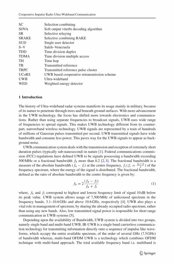
Coherent IR-UWB RAKE receivers are attributed with the knowledge of channel estima-tion before signal reception takes place at the receiver. A copy of the transmitted signalneeds to be known beforehand for evaluating the channel estimation. The coherent RAKEreceiver is a culmination of matched filters also called correlators, where each correlator ismatched to the delayed replica of the same transmitted signal. The correlator output thencombines the energy obtained from each of these multipaths, thereby exploiting multipathdiversity. As seen in Fig. 1, the received UWB signal r(t) is first passed through a low noiseamplifier (LNA), to remove any kind of noise present in the received signal. The filteredreceived signal r ′(t) is then delayed by τ units for each multipath and correlated with thesame transmitted signal m(t) which acts as a template. The correlated data is then integratedand multiplied with suitable weights w0, w1, . . . , wn−1, obtained from channel estimation.Finally the weighted signal is combined using maximal ratio combining (MRC) technique,
Fig. 1 Architecture of a UWB RAKE receiver with N parallel fingers [13]
123

R. Hazra, A. Tyagi
to recover the original symbol b j where b j ε (−1, 1). These weights are determined adap-tively from channel estimation. The most commonly used RAKE receivers are All RAKE(ARAKE), Partial Combining (PRAKE) and Selective Combining (SRAKE). For extractingenergy, ARAKE receiver exploits each and every multipath, PRAKE receiver exploits thefirst M arriving multipath and SRAKE receiver exploits only the strongest multipath. Afterextracting energy from the various multipaths, it is then combined using MRC or equal gaincombing (EGC), in order to recover the original symbol b j . The bit error probability (BEP)of the UWB system using coherent RAKE receiver with PPM technique for detection oftransmitted symbol, depends on transmitter receiver distance, number of correlators (fin-gers), combining schemes and the type of the channel used [16]. The channel used furtherdepends on SNR of the system and the number of correlators required to extract multipathenergy [17]. As far as performance is concerned, ARAKE receiver outperforms the otherreceivers such as PRAKE and SRAKE. The conclusion obtained from the results prove that,SRAKE receiver gives a better BER performance compared to PRAKE receiver, when it’scombined with MRC [18] and the number of correlators is increased. Even though SRAKEreceiver requires perfect channel estimation to measure path gain, yet it outperforms PRAKEreceiver in performance, having less complexity and requiring less accurate channel esti-mation. It can also be stated that as far as detection of transmitted signal in coherent UWBsystems is concerned, PRAKE receiver combined with MRC shows better performance, thanwhen combined with EGC, while for SRAKE receiver, both EGC and MRC strategies showsimilar performance [18]. Coherent IR-UWB RAKE receivers perform better, compared tonon-coherent IR-UWB receivers in terms of less noise, high data rate and less fading. How-ever, the drawback of using a IR-UWB RAKE receiver is its complexity. This complexityis however due to the presence of a number of correlators present in the receiver, to extractmultipath energy from the multipaths.
2.2 Non-Coherent IR-UWB Receiver
One of the main advantages of using IR-UWB system for low complexity transmission, is itsability to employ non-coherent receivers even in dense multipath propagation scenario [19].Non-Coherent IR-UWB receivers do not have any information regarding channel estimation,yet it exploits multipath diversity. Despite distortion and multipath propagation, non-coherentIR-UWB receivers can extract comparable amount of energy from the multipaths [20]. Non-Coherent IR-UWB receivers are an advantage over coherent IR-UWB receivers, as it requiresless complexity and less cost, but only at the expense of poor BER performance. The non-coherent IR-UWB receivers are classified as transmitted reference (TR) receiver, differentialtransmitted reference (DTR) receiver, transmitted reference pulse cluster (TRPC) receiver,energy detector (ED) receiver and weighted energy detector (WED) receiver, which are brieflydiscussed in the subsequent sections.
2.2.1 Transmitted Reference (TR) Receiver
Non-Coherent IR-UWB receiver overcomes the problems faced by coherent IR-UWB RAKEreceiver. TR transceivers operate by transmitting two pulses every symbol period. The firsttransmitted pulse is an unmodulated (reference) signal, followed by a second pulse, whichcontains information bearing data modulated pulse. The first, i.e. reference pulse is delayedrelative to the data modulated pulse by an amount exceeding the delay spread of the channel[21]. PPM and PAM modulation and demodulation techniques are used for transmissionand reception of UWB signals. Reception is possible by autocorrelating the received signal.
123

Cooperative Impulse Radio Ultra-Wideband Communication
Fig. 2 TR receiver
After autocorrelation, the resultant signal is then integrated and finally the original symbol isextracted using a decision threshold. The receiver is attractive because of its simplicity andlower data rate due to the transmission of the reference pulses. The transmitted TR signal isdenoted by:
sTR(t) = √Ex
∞∑
j=−∞x
(t − jT f − c j Tc
) + √Ex x(t − jT f − Td − c j Tc − b j/Ns δ (2)
where x(t) represents the transmitted waveform with duration [0, Np],√Ex represents thesignal energy, Td is the delay between the reference and data modulated pulses and is largerthan the delay spread to avoid ISI, Np is the pulse duration, Tc is the chip duration, c j is theTH sequence, T f is the frame duration, each symbol b j ∈ (0, 1, . . . , M − 1) is transmittedNs times (repetition factor), δ is the separation between adjacent symbols and n(t) is thenoise. Received TR signal is represented as:
rTR(t) = √Ex
∞∑
j=−∞x
(t − jT f − c j Tc
)
+ √Ex x
(t − jT f − Td − c j Tc − b j
Nsδ
)+ n(t). (3)
In Fig. 2, which represents a TR receiver, received signal rTR(t) is initially filtered bypassing it through a bandpass filter (BPF). The filtered received signal r ′
TR(t) is then auto-correlated with r ′
TR(t − Td) and the resultant is then integrated over the time duration Tint ,to recover the original symbol using decision criteria. The decision statistic is approximatedas:
ZTR =N f −1∑
j=0
iT f +Td+Tint∫
iT f +Td
r ′TR(t)r ′
TR(t − Td)dt (4)
where, T f is the frame duration, Tint is the integration duration in each frame, N f is thenumber of frames and Td corresponds to the delay spacing between the reference and datamodulated pulse in each frame. It is noted that Td should be greater than multipath delayspread Tmds, such that there is no interference between the reference and data modulatedpulse [22]. The frame duration, T f is designed with the condition that T f ≥ 2Td ≥ 2Tmds.This is in order to prevent inter-frame interference (IFI) between the reference pulse in thepresent frame and data modulated pulse in the next frame [22,23]. The drawback of using a
123

R. Hazra, A. Tyagi
TR receiver is the presence of a reference signal, which acts as a noisy template leading toperformance degradation. TR systems waste half of the energy and power in transmitting areference signal [24]. The major problem associated with a TR receiver in comparison to anideal matched filter (MF) receiver is, it suffers a loss of 6 dB, where 3 dB is contributed dueto the transmission of reference pulse and the rest 3 dB due to the transmission of two pulsesper bit [20].
2.2.2 Transmitted Reference Pulse Cluster (TRPC) Receiver
The major problem faced by a conventional TR system is the requirement of a long wide-band delay line. A loss of 3 dB due to the presence of reference pulse, further leads to thedegradation in the performance of a TR system. It is overcome using IR-UWB TRPC system[25], consisting of multiple pulses having uniform and compact spacing. TRPC signal issaid to repeat after every 2Td seconds, where Td corresponds to the spacing between theunmodulated reference pulse and the data modulated pulse. The uniform spacing is commonamong all the pulses belonging to the same cluster. The pulses carry the same polarities,irrespective of their position i.e. odd or even. The information to be transmitted is obtainedfrom the relative polarities of the pulses at odd and even position. Each pulse in a TRPCsystem acts as a reference for its subsequent pulse, and at the same time, acts as informa-tion carrying data pulse for its previous pulse. TRPC receiver can also be classified as anautocorrelation (AC) receiver, because it also works by autocorrelating the received signal.The resultant autocorrelated signal is then integrated and finally the transmitted symbol isrecovered using a decision mechanism. The results obtained from the simulation [25] furtherconfirms that, TRPC system outperforms a TR system, because of its low implementationcomplexity, stability, robustness, high data rate and use of short delay lines.
2.2.3 Differential Transmitted Reference (DTR) Receiver
Transmitted reference (TR) system wastes a chunk of the energy and power during transmis-sion of a reference pulse. So, it is replaced by a DTR system. Since DTR doesn’t transmita reference pulse, it increases the data rate and thus, saving transmission energy. As seen inFig. 3, DTR receiver works by correlating the received signal rDTR(t) sent over the presentframe with the delayed signal sent over the previous frame rDTR(t − D). The resultant auto-correlated signal is then integrated over the time interval using an integrator. The integratorresult uses the decision criteria to recover the original symbol b j [26]. The DTR signal trans-mitted in the present frame, acts as a reference for information carrying data pulse in the
Fig. 3 DTR receiver
123

Cooperative Impulse Radio Ultra-Wideband Communication
Fig. 4 DTR transmitter
next frame [27]. As seen in Fig. 4, data pulse b j sent in the present frame over the channelis differentially modulated using the pulse a j,m−1 obtained in the previous frame [28].
The transmitted DTR signal is represented as:
sDTR(t) =∞∑
j=−∞
N f −1∑
m=0
a j,m x(t − jTb − mT f − cm Tc). (5)
where sDTR(t) represents the transmitted DTR signal, x(t) the Gaussian pulse used for trans-mission, cm the time-hop (TH) sequence, Tb the symbol period for the data signal, T f thetotal frame time, N f is the number of frames and Tc the chip interval corresponding to the THsequence. As seen in Fig. 4, b j ∈ (−1, 1) is the information symbol which is differentiallymodulated with aj,m−1 to produce a j,m . Here, aj,m−1 corresponds to the differentially modu-lated data sent over the previous frame whereas, a j,m represents the differentially modulateddata sent over the present frame. The differential modulated data a j,m follows a differentialencoding procedure which states that:
a j,m ={(
a j−1,N f −1b j), m = 0
(a j,m−1b j
), 1 ≤ m ≤ N f − 1
(6)
2.2.4 Energy detector (ED) Receiver
Energy detection is a low complexity non-coherent approach used for the reception of UWBsignals, which is achieved at the expense of BER degradation. ED receivers don’t requirechannel estimation and hence is less sensitive to synchronization errors [29]. On-off keying(OOK) is the commonly used non-coherent modulation technique used for energy detection.Figure 5 shows the detection procedure in conventional ED receiver. Here, the detectionuses OOK modulation scheme. In order to perform detection, the received UWB signalr(t) is initially passed through a BPF, where it gets filtered by a BPF to give r ′(t). Thefiltered received signal r ′(t) is then passed through a square law device, which is used for
Fig. 5 Non-coherent ED receiver
123

R. Hazra, A. Tyagi
squaring the signal. After squaring, the resultant signal is then integrated using an integratorhaving integration window Ti . Finally, the original transmitted symbol b j is recovered usinga detection mechanism. The two most challenging issues faced by ED receivers duringreception are, estimation of optimal threshold and finding out the synchronization dumppoints of the integrator [29]. The determination of synchronization and optimum thresholdis possible by estimating the signal and noise statistics.
During reception, the increase in the number of parallel integrator branches leads to theincrease in integration time resolution of the receiver and therefore, increases the chancesof obtaining a lower BER at the cost of computational and hardware complexity. The majordrawback associated with an IR-UWB ED receiver is that, it is sensitive to noise in thechannel and also interference.
2.2.5 Weighted energy detector (WED)
The non-coherent IR-UWB receivers discussed are all contaminated by noise, which leadsto performance degradation. So, WED receiver [30] is proposed which is responsible foralleviating noise. As seen in Fig. 6, WED initially squares the received signal r(t) and thenpasses the squared signal through a bank of M parallel integrators. Each of these M integratorsis provided with an integration time window Tm with a maximum time interval of Ti . Theintegrator outputs are weighted individually and then linearly combined to give a decisionstatistic. The weights a0, . . . , aM−1 are evaluated adaptively from the signal energy availableat the output of the corresponding integrators y0, . . . , yM−1, leading to an improvement inSNR ratio [31]. The weighting coefficients a0, . . . , aM−1 will have a higher value, if the signalstrength is good, but a lesser value if the strength of the signal is weak. Here, M correspondsto the number of integrators used. From the review it can be concluded that, WED receiveroutperforms the conventional ED receiver by 2 dB [31–33]. However, the improvement inperformance of the WED receiver comes at the expense of increased hardware complexity.So, WED receiver can be regarded as the one which outperforms all the other non-coherentIR-UWB receivers.
3 Cooperative System Model
Cooperative communication is a new technology in wireless networks, where the cooperativenodes or users help each other to improve the overall system performance, coverage and
a0
Y0
( )2
aM-1
Decision
YM-1
r(t)
Fig. 6 Weighted energy detector (WED) [33,34]
123

Cooperative Impulse Radio Ultra-Wideband Communication
Fig. 7 Cooperative systemmodel [15,34]
Select one Relay
SN
RN0
DNRN1
RN2
transmission reliability. In each such cooperative model, there are three kinds of nodes,source node, relay nodes and destination node. A communication process of a cooperativeUWB system involves a pair of source and destination node and M relay nodes, whereM indicates number of relay nodes. There are three steps in a cooperative communicationprocess. At first, a pilot symbol is broadcasted by source node to all the relay nodes. Atthis juncture, due to the obstacles in the links between the source and relay nodes, links arenot guaranteed. The second step is to select the relay node with the best BER performance,from among all the relay nodes in the communication process. This step is the most vitalamong all the three steps of cooperative UWB system model, because once the channelfading in the source relay and relay destination link is known, the route with the best BERperformance is obtained. Copies of pilot symbol sent by the source node are received by allthe relay nodes as seen in Fig. 7. The relay nodes then receive the pilot symbols sent by thesource node, which are then demodulated and the channel fading in the source relay linkhi (t) where, (i = 0, 1, 2, . . . , M − 1) is evaluated. Once the channel fading is known, SNRcan be evaluated. Each relay node then transmits the pilot symbols as well as the obtainedSNR to the destination node. Hence, the destination node will receive M copies of the pilotsymbol sent by the source node. At the destination node, pilot symbols received from Mrelay nodes are demodulated and the channel fading in relay destination link gi (t) where(i = 0, 1, 2, . . . , M − 1), is evaluated. As a result, the received copies of the pilot symbolobtained at the destination node will have different SNR values. Finally at the destination,the copy of the pilot symbol with the highest SNR or best BER performance is noted andthe path corresponding to that relay node is selected. Once the relay node with the best BERperformance is selected, the source node finally sends the information to the destination nodevia this path. Thus, the selected relay node acts as a medium for communication between thesource node and destination node [34].
4 Relay Strategies
In Cooperative communication, terminals use relaying to jointly transmit information due tothe broadcast nature of wireless medium. The relay protocols are classified as Fixed protocols,Adaptive (selective) protocols, Incremental protocols and Coded cooperative communicationprotocols, which are discussed in the following sub-sections [15].
123

R. Hazra, A. Tyagi
4.1 Fixed Protocols
The protocols are fixed in nature and are classified as: Decode and Forward (DF), Amplifyand Forward (AF) and Detect and Forward (DTF).
4.1.1 Decode and Forward (DF)
Decode and forward (DF), which is a digital scheme, works in regenerative mode. The relaynode, situated between the source and the destination node, first decodes the transmittedcodeword sent by the source node using soft output Viterbi decoding algorithm (SOVA)in the first time slot. It then encodes and re-transmits or forwards the decoded codewordto the destination node in the second time slot. As a result, any errors at the relay stationcan be corrected and avoided from propagating further to the destination node because ofits error correcting capabilities. DF scheme is widely used to process the data in the relay.This is because, the wireless transmission uses digital modulation and the relay has enoughcomputing power. The advantage of this method is simplicity and adaptability to channelconditions. Noise does not propagate to the next stage in this scheme [15,35].
4.1.2 Amplify and Forward (AF)
Amplify and forward (AF), which is an analog scheme, works in non regenerative mode.In this scheme, a relay receives the transmitted signal sent by the source node in the firsttime slot, amplifies it and then retransmits or forwards it to the destination node in the nextphase. This is the most preferred method when relay has limited computing time or poweravailable at the time delay. Since it is assumed that in AF, the destination knows the channelstate information (CSI), it is important to introduce some sort of mechanism to exchange orestimate the information in the implementation. Noise amplification is a major issue for thistechnique [15].
4.1.3 Detect and Forward (DTF)
In DTF scheme, code repetition is initially applied at the transceiver of source and relaynode. In the first time slot, the relay node detects or demodulates the transmitted codewordsent by the source node using a hard decision decoding technique. The detected symbols arethen forwarded to the destination node, under the same constraint power in the second timeslot [36–38]. Signal processing in both these schemes, DF and DTF are similar. As far asperformance is concerned, under similar conditions, DF scheme outperforms DTF scheme by3 dB at a BER of 10−4 for a dual hop IR-UWB system. This is because, DF scheme uses errorcorrecting capabilities for decoding of information at the relay node, whereas DTF schemejust demodulates or detects the information using hard decision. So, information availableat relay node in case of DTF is an uncoded version of DF, which is error prone, whereas incase of DF scheme, it is error free. AF scheme is the most erroneous among all the fixedprotocols discussed, since it uses no coding technique to decode or detect the information atthe relay node. Further, the information at relay node is amplified before it is forwarded tothe destination node, hence the error gets magnified and the performance degrades.
4.2 Adaptive Protocols
The Fixed protocol scheme suffers from error propagation, thus degrading its performance.Hence, we resort to adaptive relay scheme which adapts its own transmission format accordingto the channel condition between the source and relay node [15].
123

Cooperative Impulse Radio Ultra-Wideband Communication
4.3 Incremental Protocols
The spectrum efficiency of Fixed and Adaptive protocol suffers, as the source and relaynode has to repeat the message. This scheme solves the problem of spectrum efficiency ofthe system, because the transmission of information from source node depends on feedbackfrom the destination node. If the feedback from the destination node is positive, then directtransmission is preferred, else if the feedback is negative, relaying is required [15].
4.4 Coded Cooperative Communication Protocols
This protocol is robust and improves spectrum efficiency by simultaneous reception of varioussignals in the same time slot.
Location of the relay also plays a vital role in the system performance. The channel qualityof the second hop gets worse and BER improves when the relay moves closer to the sourceand away from the destination. So, in order to achieve an overall good BER performance, itis important to maintain a good channel quality in the first hop, compared to the second hop.
5 Cooperative UWB Communication: A Research Perspective
The initiative to exploit the vast unlicensed spectrum from 3.1 to 10.6 GHz and the regulationto use commercial UWB technology by FCC, has caught the eyes of various researchers inindustrial and academic institutions. The attractive features of UWB technology has lead toits usage in various commercial applications, specifically in the area of short range com-munication. In order to overcome multipath fading, cooperative diversity has emerged asan effective scheme, which helps in improving the QoS of the wireless network. The basicfunctionality of cooperative diversity is to cooperatively route the data via multiple nodes, inorder to improve the overall network performance.
5.1 UWB Relay Communication and Detection Using a Coherent (RAKE) Receiver
According to the authors, Maichalernnukul et al. [39], the proposed scheme consists of a UWBrelay system with a SRAKE receiver using pilot aided channel estimation, for reception oftransmitted signal. The relay system is provided with multiple antennas and uses cooperativeDF technique for reception. The channel characteristic of the transmitter, relay and receiver,is the main criteria for the performance of the proposed relay system. The channel model isbased on Saleh–Venezuela (S–V) model [40]:
h(t) =L−1∑
l=0
αlδ (t − τl) . (7)
where h(t) is the channel response, L is the number of multipath components, l is the pathindex, αl is the path coefficient and τl is the path delay. The single antenna DF relay schemehelps in reducing the path loss and also exploits the multipath diversity using IR-UWBSRAKE receiver. The transmitted signal at the source is:
s(t) =Nb−1∑
i=0
bi gT (t − 2iTb). (8)
123

R. Hazra, A. Tyagi
where, Nb is the number of data modulated pulses, bi ∈ (−1, 1) is the binary data with equalprobability, gT is the gaussian monocycle waveform with width Tg, Eb is the energy per bit,Tb is the bit duration and Np is the number of pulses. The channel estimation is improved bytransmitting the pilot signal before transmitted signal s(t). Two slots, which are of durationTb are required to either relay a pilot pulse or a data modulated pulse. The pilot signal p(t)is given as:
p(t) =−1∑
i=−Np
gT (t − i2Tb). (9)
The relay receives the signal sent from the transmitter, in the first time slot. The receivedsignal r(t) is given by:
r(t) = hT (t)∗s(t) + n(t). (10)
r(t) =L−1∑
l=0
αT s(t − lTg
) + n(t). (11)
The output of the received signal is now combined using SRAKE scheme and finally inte-grated:
zR =(2i+1)Tb∫
2iTb
r(t)hT (t − 2iTb). (12)
The second time slot is used to transmit the detected data bit b′i = sign(zR) from relay to the
receiver as:
sR(t) =Nb−1∑
i=0
b′i gT (t − (2i + 1)Tb). (13)
The received signal r(t) at the receiver (destination) is denoted as:
r(t) =L−1∑
l=0
αT 2sR(t − lTg) + n(t). (14)
r(t) = hT 2(t)∗sR(t) + n(t). (15)
where, sR(t) is the transmitted signal from the relay to the destination, hT (t) is the channelimpulse response from source to relay, hT 2(t) is the channel impulse response from relay tothe destination, ∝T is the fading coefficient from source to relay, ∝T 2 is the fading coefficientfrom relay to destination and n(t) is the zero mean AWGN process. Finally, the overall averageBER and SNR is evaluated from the decision variable zR obtained at the destination. Thesame principle is also applied in the case of two antenna relay system, to transmit signalfrom source to destination, through a relay using DF scheme. SRAKE receiver with fivefingers outperforms SRAKE receiver with one finger by 5 B at a BER of 10−2, since theformer captures more energy compared to the latter, even at the cost of increased complexity.Similarly, using two antennas in a SRAKE system outperform those using single antennarelay by 2 dB at a BER of 10−2. This is due to the spatial diversity gain obtained usingtwo antennas available at the relay. However under perfect channel estimation, the systemconsisting of two antennas with five fingers gives a SNR gain of 2 dB at a BER of 10−2, overthe system consisting of single antenna with ten fingers. The excellence of a two antenna
123

Cooperative Impulse Radio Ultra-Wideband Communication
relay system using more than one finger is because of the decaying power delay profile(PDP) characteristic. It is also inferred that, increase in number of antennas gives a betterBER improvement than increasing the number of fingers.
Maichalernnukul et al. [41], proposed a two hop DTF multiple relay system for coherentIR-UWB system. Each of these relay are equipped with multiple antennas. In the first hop,information is transmitted from the source to the relay node. At each relay node, detectiontakes place using a PRAKE receiver, thereby leading to spatial diversity. Similarly in thesecond hop, detected information is forwarded from the relay to the destination using DTFrelay scheme. The channel model used is IEEE 802.15.3a. Once received signal is knownat the destination, SNR can be easily evaluated. If SNR is known, BER can also be calcu-lated. The use of a coherent IR-UWB receiver at the relay and destination requires accuratesynchronization because of channel estimation being known. UWB relay system has a betteroutage probability than a non-relay UWB system, because it reduces the path loss by exploit-ing the short link distances in two hops. The increase in number of antennas i.e. M at therelay (where M = 6, Q = 1), produces a superior outage performance gain of 7 dB at a BERof 10−3 in comparison to the increase in number of relays i.e. Q (where M = 1, Q = 6).UWB system with more number of relays i.e. Q = 4 and less number of RAKE correlatorsi.e. L = 10, provides a better outage probability of 3 dB at a BER of 10−3, than a UWBsystem with a single relay i.e. Q = 1 and having more number of fingers (correlators) i.e.L = 40. So, it can be concluded by saying that the use of multiple antennas saves the numberof RAKE fingers and relays required to achieve low outage probability.
Shirazi et al. [42] proposed a novel strategy named UWB based cooperative retransmissionscheme (UCoRS). In this scheme, nodes do not move and as a result, information is sent onlyonce. Also, the process of ranging is performed only once. The scheme achieves multiuserdiversity technology for both proactive and reactive settings, by using all the properties of IR-UWB. In proactive setting, decision is made prior to transmission of data, while for reactiveenvironment, decision is made after the relays receive the data. The inference drawn from thepaper tells that, the proactive performance is similar to maximum throughput. The reactiveand proactive relay schemes produce a much better result than non-cooperative scheme. Thepacket delivery ratio (PDR) improves with increase in number of relays in UCoRS and ismaximum at 0.7 for proactive setting, compared to reactive setting which has a value of 0.6. Itis also observed that, throughput improvement in UCoRS is at the expense of minimization inthe amount of control packet overhead, thereby eliminating energy cost in coherent IR-UWBreceivers.
Shirazi et al. [43] have analyzed the throughput of optimal cooperative strategy for proac-tive and reactive setting, in both static and mobile scenario. It can be concluded from theresults that, considerable diversity gain is achieved at a low implementation cost. In UCoRS,the exchange of control packets is reduced for both static and mobile cases, thus reducingthe control packet exchange cost in UWB receivers.
Abou-Rjeily [44] proposed a non orthogonal symbol by symbol cooperation strategy forcoherent IR-UWB systems using a single relay PPM constellation. The symbol by symbolcooperation strategy using PPM constellation is achieved within one symbol duration. It canbe inferred from the results that, the proposed scheme shows an improved data rate comparedto M-ary PPM (M-PPM) system. UWB system using cooperative DF scheme gives a muchbetter BER performance, than cooperative AF and non-cooperative system. The performanceimproves, as integration interval increases.
Abou-Rjeily et al. [45] proposed an optimal DF cooperative scheme for detection oftransmitted symbol using a coherent IR-UWB RAKE receiver in CM1 and CM2 environment.Since the coherent IR-UWB systems have channel state information (CSI) known at the
123

R. Hazra, A. Tyagi
receiver end, RAKE receivers are used at relays and destination. The cooperation strategyused is either coded or space time in nature and is as follows. In the first hop, each one of the Krelays listens to the transmitted signal s(t) at the source, during the L symbol duration. Afterdecoding the information sent from the source, RAKE reception takes place and the decisionscorresponding to the first L symbols are taken. The relays then transmit simultaneously duringthe second hop and the information is then forwarded to the destination. Once receivedsignal is intercepted at destination using a RAKE receiver, SNR can be known. With thehelp of SNR, BER performance of the receiver can also be calculated. The performance of acoherent IR-UWB RAKE receiver using selective relaying (SR) strategy shows a much betterBER performance than a UWB receiver using fixed relaying (FR) strategy. Even in case oferrors, UWB receiver employing SR strategy shows robustness and hence, outperforms UWBreceiver using FR strategy.
Hamdi et al. [46], claims that the proposed time reversal technique used for the detectionof transmitted symbol using a coherent IR-UWB receiver, produces a performance equivalentto that of a simple IR-UWB RAKE receiver, without increase in complexity of the receiver.In this technique, the transmitting nodes uses pre-diversity filter, in order to filter the UWBsignal before transmission. The time reversal signal processing technique at transmitter sideexploits the rich multipath scattering, for achieving signal focusing. The proposed methodis based on time reversed channel impulse response (CIR), for transmitter side pre-filtering.Time reversal technique is applied to the transmitted signals by the source and relay nodes,for reducing the receiver complexity. The transmitted signal is recovered at destination bypassing the received signal through a pre-rake filter, whose CIR is determined from source–relay, relay–destination and source–destination. The cooperative strategy is as follows. Thesource pre-rakes the signal by evaluating the source–relay channel in the first time slot. In thesecond time slot, the source and the relay pre-rakes the signal related to source–destinationchannel and relay–destination channel respectively. The channel follows the specifications ofS–V model. However, time reversal coherent IR-UWB receiver is more robust to estimationerrors compared to the traditional IR-UWB RAKE receiver. It is also noted that the BEPperformance of time reversal IR-UWB RAKE receiver improves not only with the increasein number of frames, but also with the addition of relay nodes.
Xu et al. [47], proves that there is a BER performance improvement in coherent IR-UWBsystem using cooperative dual hop AF scheme, over non-cooperative scheme in multipathfading UWB channel. The relay strategy is as follows. The source node broadcasts the datato the relay node in the first hop. At the relay node, data is amplified using AF strategy andthen combined using a RAKE receiver. Once, RAKE combining is performed in the RAKEreceiver, the received signal is normalized in energy. In the second hop, the result of thefirst hop, i.e. the normalized signal energy is retransmitted by the relay node. Here, data isforwarded to all the destination nodes, with a constant transmission power. Finally at thedestination node, the decision is taken on the recovered information bits, according to theoutputs of the RAKE combining. Once the received signal at destination is known, SNR canbe evaluated. The relay’s location also plays a major role in improvement of the performanceof IR-UWB cooperative relay system.
Zu et al. [36,48], claims that performance improvement in IR-UWB system is achievedusing dual hop cooperative DTF and DF relaying strategies in dense multipath channel. Thecooperative DF relaying strategy uses convolutional coding for decoding of information inthe UWB system. The channel follows the specifications of S–V model. The cooperativestrategy is as follows. In the first hop, different channel encoders are used to encode thedata bits, which are modulated using DS-BPAM scheme. Once pulse shaping is performed,the source node using a single antenna, broadcasts the signal to the relay node. Any of the
123

Cooperative Impulse Radio Ultra-Wideband Communication
relay strategy like DF or DTF can be used to process the received signal in the relay node.Using DTF strategy, the relay detects the signal sent from the source with a hard decision.The DF relay system then decodes the signal sent by the source, using soft output viterbidecoding algorithm (SOVA). In the second hop, the data which is processed, is retransmittedand forwarded to the destination node, with a constant power. The destination node thentakes appropriate decision with respect to the outputs of RAKE combining obtained fromthe RAKE receiver. Once the received signal is known at the destination, SNR can also beevaluated. Moment generating function (MGF) is obtained by using Gaussian quadraturemethod, which is one of the approaches for evaluating average BER performance at the relayand destination. The source and the relay nodes are employed with a receiver, for performingcode repetition using cooperative DF and DTF scheme. Coherent IR-UWB RAKE receiverusing DF scheme gives a much better BER performance compared to cooperative DTFscheme in both line of sight (LOS) and non line of sight (NLOS) environment.
Xu et al. [49], in their work, compares the performance of coherent IR-UWB systemsusing dual hop cooperative AF strategy in CM3 and CM4 channel. The proposed schemeuses a non regenerative AF relay scheme instead of a regenerative scheme, so as to avoidsystem complexity. The cooperative strategy is as follows. The signal sent by the source nodeis received by the relay node during the first hop and then amplified. The amplified signal isthen sent to the destination during the second hop. The received signal obtained at the receiveris then used to find SNR. The path loss and BER criteria are the principle conditions whichdetermine the system performance. Once the SNR is known, BER can also be evaluated. MGFis obtained by using the Gaussian quadrature method, which is responsible for the evaluationof average BER performance. CM3 being a LOS channel outperforms CM4 channel, NLOSchannel.
The authors, Yazdi et al. [50], claims that the average BEP of a coherent IR-UWB systememploying TH-PPM scheme, is improved using a cooperative DF relay protocol in compar-ison to a non-cooperative scheme in IEEE 802.15.4a UWB environment. The cooperationstrategy is composed of two time slots, each of which is given equal time intervals. Here,in the first time slot, the source broadcasts its signal to the destination node and the relaynodes. The source node then becomes silent and only the relay node communicates with thedestination in the second time slot. The coherent IR-UWB RAKE receiver with K ′ fingerat the destination node, captures K ′ rays from the first clusters of source–destination UWBlink during the first transmission time slot. Similarly during the second time slot, IR-UWBRAKE receiver with K ′ finger at the destination node captures K ′ rays from the clusters ofrelay–destination UWB link. As a result, signal decoded by the relay using DF strategy isforwarded to the destination node. So, once the received signal is available at the destination,SNR can also be calculated. The decision variable obtained from the received signal at thedestination node helps in evaluating the characteristic function (CF). Once the CF is known,it is easy to evaluate the BEP of the UWB system which depends on SNR, number of framesand the position of relay. The BEP improves with increase in number of frames and SNR.Also, when the relay is situated nearer to the source, BEP further improves.
From the work of Maichalennukul et al. [51], it can be concluded that, UWB systemsusing dual hop cooperative strategy and multiple antennas at the relay, enjoys a higher SNRadvantage over the ones using a single antenna at the relay. The relay strategies used forcooperative IR-UWB communication are AF and DTF. The assumption is that the relay par-tially knows the channel coefficients of the source–relay and relay–destination link channels.The cooperative scheme is as follows. In the first hop, in order to receive the transmittedsignal from source, the relay selects only the j th receive antenna. Similarly, the relay selectsonly the j th transmit antenna to transmit a processed version of the signal to its destina-
123

R. Hazra, A. Tyagi
tion. For the first hop, the transmitted and received signal is same while considering DTFrelaying scheme. The relay performs the detection by estimating the transmitted bit sentby the source. It then makes a hard decision on it. The hard decision technique using DTFscheme gives a better performance, compared to one using an AF relaying scheme. In secondhop, signal received at relay is forwarded to the destination. Finally, a decision variable isobtained from the received signal available at the destination node. Once the decision variableis obtained at the destination, SNR can be easily evaluated. The same cooperative schemei.e. DTF and AF is also applied to a UWB system having a single antenna at the relay node.It is also inferred from [51] that, the performance of the coherent IR-UWB system usingcooperative AF scheme, and having multiple antennas i.e. M > 1 at the relay with antennaselection i.e. Q = 1 improves as M increases and decreases with increase in Q. It can beconcluded by saying that with increase in the number of antennas, the outage performance ofthe UWB system using cooperative AF relay scheme improves, while with increase in num-ber of relays, the outage performance of the UWB system using cooperative DTF schemeimproves.
The authors, Yang et al. [52], proposed the best scheme for cooperative relay selection,based on distance information for detection in coherent IR-UWB receiver. The relay selectiondepends on the channel conditions between the source–relay and relay–destination links. Theproperties of UWB system such as high precision ranging and positioning property, givesthe distance information required for the relay system. The cooperative relay strategy usedis AF, whereby the signals sent from the source node are first combined using a RAKEreceiver and then amplified at the relay. The amplified signal at the relay is then forwardedto the destination node. Detection of received signal at the relay and destination is doneusing RAKE receiver, and then combined using MRC technique. The proposed IR-UWBRAKE receiver using cooperative AF scheme for the detection of transmitted symbol, givesa much better performance than IR-UWB RAKE receiver using all participating scheme,opportunistic scheme and no relay scheme.
The authors, Pan et al. [53], analyze the performance of coherent TH IR-UWB receiverusing AF and DF cooperative relay strategies, in presence of multi-user interference (MUI).The performance of TH IR-UWB system using cooperative AF and DF relay strategies isevaluated in terms of outage probability and average BEP. It is also learnt from the surveythat, MUI degrades the SNR of the received signal at the relay and destination and hence,affects the BER performance and outage probability.
The authors, Maichalernnukul et al. [54], discuss about the performance of a DS andTH UWB system using cooperative AF and DF relay scheme, in presence of a single tonenarrowband (NB) interferer, both in optimistic scenario and worst case scenario. The effectof NB signals on UWB receiver is significant and in extreme case, these signals jam a UWBreceiver completely. The cooperation strategy consists of two phases. In the first phase, thesource broadcasts the information to the destination and relay. After receiving the signal sentfrom the source, RAKE combining takes place using a RAKE receiver, followed by amplifi-cation using AF strategy. In the second phase, the relay forwards the amplified informationto the destination. Since the CSI of the source–relay link is known to the source, and thedestination is also aware of the CSI of the source–destination and relay–destination links,coherent IR-UWB RAKE receiver is used at the relay and destination. The channel is takento be constant over the cooperation period. In presence of NB interference, UWB cooperativerelay system offers a performance advantage of 5 dB at a BER of 10−4 over coherent IR-UWB non-relay system. Similarly, cooperative UWB DTF relay system also offers a superiorperformance gain of 1–2 dB at a BER of 10−4, over UWB AF relay system, in presence of NBinterference. DS UWB system with cooperative DF scheme, outperforms TH UWB system
123

Cooperative Impulse Radio Ultra-Wideband Communication
with DF scheme, DS UWB system with AF scheme, TH UWB system with AF scheme,single link (no relay) DS UWB system and single link (no relay) TH UWB system by 0.5, 1,1.5, 4 and 5 dB, respectively at a BER of 10−5, under the condition that all the schemes useMMSE combining. So, it can be said that DS-UWB system also outperforms a TH-UWBsystem. Coherent IR-UWB system using cooperative AF and DF relay strategy with MMSEcombining scheme, gives similar performance for both optimistic and worst case scenario,but while using MRC combing, performance in optimistic scenario is found to be better thanworst case.
5.2 UWB Relay Communication Using Non-Coherent Receiver
5.2.1 Transmitted Reference (TR) Receiver
UWB system having a TR receiver for detection of transmitted bit with cooperative DF relaystrategy is proposed by Hoctor et al. [34]. The combination of UWB communication andcooperative scheme improves the performance and reduces the power consumption. In thisscheme, the transmitted signal consists of two pulses transmitted per frame, i.e. a referencesignal followed by a delayed data modulated signal. The transmitted signal is modulatedusing binary phase shift keying (BPSK) scheme and is represented as:
s(t) =∞∑
k=0
Ns−1∑
j=0
[p
(t − k Ns T f − jT f
) + bk p(t − k Ns T f − jT f − Td
)]. (16)
where, bk ε (−1, 1) represents a binary information, p(t) a pulse signal, Ns the number ofsymbols, T f a frame period and Td is the spacing between the reference and informationcarrying pulse. In each frame two pulses are transmitted, i.e. a non modulated referencepulse followed by an information carrying modulated pulse. The received signal r(t) afterbeing passed through a BPF is written as:
r(t) =∞∑
k=0
Ns−1∑
j=0
[g(t − k Ns T f − jT f ) + bk g(t − k Ns T f − jT f − Td) + n(t)
]. (17)
where, g(t) = p(t) ∗ h(t) is the aggregate signal obtained after passing p(t) through themultipath channel h(t) and n(t) represents the noise. The received signal is autocorrelatedinitially and then the autocorrelated signal is integrated over time interval. The resultantintegrated signal then uses the decision criteria to recover the original symbol. The channelbetween source–relay, source–destination and relay–destination follows S–V model. Thecooperation strategy is as follows. The first hop involves the signal being transmitted fromthe source to the relay. The transmitted signal is then received at the relay using a TR receiverand then amplified using AF strategy. The second hop involves the amplified signal obtainedat the relay to be forwarded to the destination. Along with the signal, evaluated SNR obtainedat the relay is also forwarded to the destination. The received signal is then detected usinga TR receiver at the destination. So, once the received signal is obtained at the destinationnode, SNR can be easily calculated. Once the SNR is known at the destination, BER canbe calculated. Hoctor [34] concludes by saying that, the BER performance of IR-UWB TRsystem using cooperative AF strategy is better in LOS environment, compared to NLOSenvironment.
Feng et al. [55], claims that BER performance of IR-UWB TR receiver is improved usingspatial diversity, employing multiple antenna features in CM2 and CM4 channel. Three
123

R. Hazra, A. Tyagi
different kinds of combining strategies such as EGC, MRC and SC are used for evaluatingthe BER performance. The author concludes by saying that more the number of antennasused at the relay and destination node, better the BER performance. This is due to the effectof spatial diversity gain. Also, using EGC combining gives similar performance as that ofMRC combining, but better than SC.
5.2.2 Transmitted Reference Pulse Cluster (TRPC) Receiver
TRPC system is superior to a conventional TR system in terms of robustness, better reliabilityand lower implementation complexity. Dong and Dong [56], introduced a novel cooperativebi-directional relay strategy which extends the coverage area and improves the performanceof IR-UWB TRPC system, in CMI and CM8 environment. IR-UWB TRPC system enjoyssome superiority over coherent IR-UWB system in terms of high sampling rate and no channelestimation. The cooperative structure is a bidirectional network, with two relays between twousers. In the cooperation process, xor operation is performed by the relay over its received bits,and is actually a combination of physical network coding (PNC) with repeat accumulate (RA)channel coding. The information exchange through channels h1, h2 is possible using relay 1and through channels h3, h4 using relay 2. Multiple access (MA) and broadcast (BC) phaseare used as a protocol in the bi-directional relay system. MA phase deals with the transmissionof the information from the source node to the relay node, while the BC phase deals with thebroadcasting of the processed information from the relay. Both these phases require a timedivision duplex (TDD) mode or frequency division duplex (FDD) for its proper functioning.The first two time slots are utilised by the MA phase, while the time slots 3 and 4 are utilisedby the BC phase. MA phase deals with the broadcasting of the information successively fromthe two source nodes during the first two time slots. Meanwhile, the information broadcastedby the source node 1 is received and decoded by both the relays in the first time slot and fromthe source node 2 in the second time slot respectively. This is followed by PNC coding whichinvolves each relay performing xor operation (xoring) with the information bits decoded fromthe two source nodes. Then each relay performs PNC coding by xoring it with the decodedbits from the two sources. In the BC phase, the PNC coded bits are then broadcasted by therelays in the BC phase using different cooperative strategies. The various strategies used are,relay combing (RC), maximum product relay section (MP-RS) and minimax relay selection(MinMax-RS). MP-RS and MinMax-RS show similar BER performance for a cooperativeIR-UWB TRPC system, but RC suffers a loss in comparison to both MP-RS and MinMax-RSstrategies.
The authors, Gao et al. [57], proposed a novel 2 way PNC detector for non-coherent IR-UWB TRPC system. The PNC detector is based on the principle of a simple autocorrelationreceiver, which suppresses MUI and exploits the use of multipath energy. In IR-UWB TRPCPNC detector, the information transmitted by the source node is first detected at the relaynode and then bitwise xor-ed. The estimate obtained from the xoring operation is then broad-casted back to achieve an efficient bi-directional relay communication. The two transmissionphases used for PNC detection are MA phase and BC phase. PNC treats the simultaneouslyreceived data signals with similar coding operation to obtain a network coded symbol forbroadcasting purpose. As a result, PNC shows a better spectral efficiency, compared to therest of the relay schemes. The channel satisfies the specifications of S–V model. IR-UWBTRPC PNC detector shows poor performance compared to TDMA detector. However, IR-UWB TRPC PNC detector is found to be similar to generalized likelihood ratio test (GLRT)receiver, but better than TR multi-user detector (MUD) and TR single user detector (SUD) inperformance.
123
Cooperative Impulse Radio Ultra-Wideband Communication
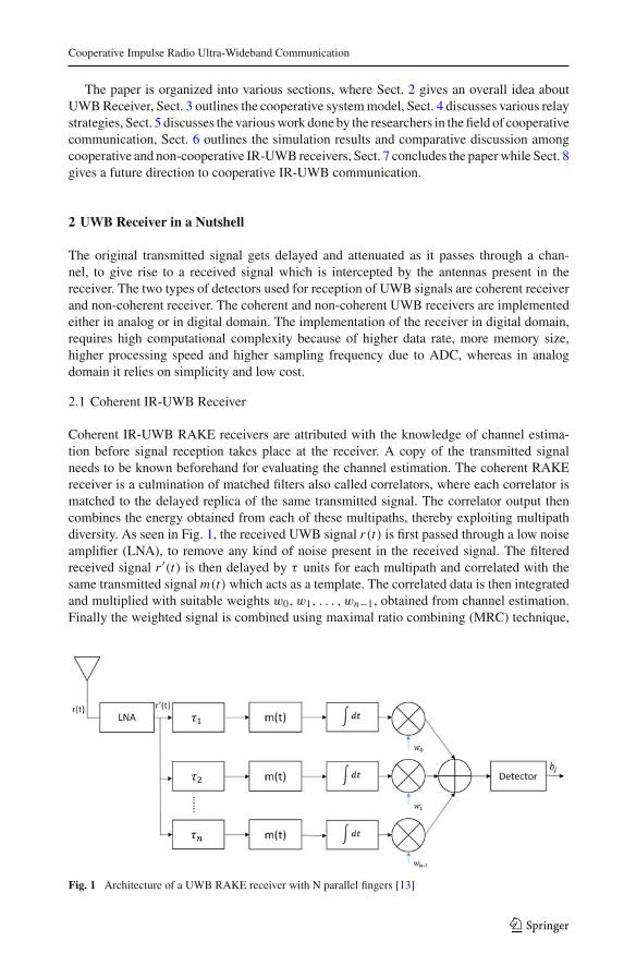
5.2.3 Differential Transmitted Reference (DTR) Receiver
The performance issues in IR-UWB TR system is greatly improved by the use of a DTR sys-tem. A DTR transmitter transmits a data sequence over a frame, by differentially modulatingthe present data symbol with a previous symbol, thus being more energy efficient and havinga higher data rate. A novel cooperative AF strategy with two hop relaying for IR-UWB systemis proposed, that exploits both these signals, the one forwarded by the relay to destinationand the other directly forwarded by the source to the destination [58]. For a non-coherentIR-UWB system, CSI is not known at the nodes. Mondelli [58], in his work uses a doubledifferential encoding technique at the source node and a single differential demodulationtechnique at the destination node. The scheme also uses log likelihood ratio criteria basedon the decision available at the destination node. The modulation and demodulation schemeused is PAM. The channel follows the specifications of S–V model. Once the received signalis available at the destination node, SNR can be easily evaluated. The proposed DTR receiverfor IR-UWB system using cooperative AF strategy and Jacobi approximation, gives similarBER performance as the one using cooperative AF strategy with equal power allocation andsupersedes the one using cooperative AF strategy with exact decision rule, simple cooperativeAF strategy and non-cooperative strategy. Also, the BER performance of all above mentionedrelay strategies used with IR-UWB DTR system degrades, as the relay moves closer to thedestination.
Wu and Hou [59] discusses about the BER performance of IR-UWB DTR system usingcooperative AF relay protocol having fixed and adaptive amplification factor. Since the infor-mation symbols are differentially encoded in a IR-UWB DTR system, a previous data carryingpulse acts as a reference to demodulate the incoming pulse. As DF protocol is more complexthan AF, AF is preferred. The cooperative strategy is as follows. The transmitted signal sentfrom the source is detected at the relay node using a non-coherent DTR receiver during thefirst hop. The detected signal is then amplified at the relay using AF strategy. The ampli-fied signal is then forwarded to the destination node, where the received amplified signal isdetected using a DTR receiver. Once the received signal is known at the destination, SNRcan be evaluated. The BER performance analysis and capacity evaluation of the coopera-tive UWB system is based on CF and non conventional Gaussian approximation (GA), inpresence of multiuser environment. The system capacity improves with increase in numberof frames and decrease in number of users. Further, in presence of two users, the systemcapacity of the cooperative IR-UWB DTR system with adaptive amplification, outperformsthe one with constant amplification.
Hamdi et al. [60], proposed a simple two hop cooperative AF relay scheme for IR-UWBsystem having a DTR receiver at the relay and destination. To limit the effects of ISI, adouble differential encoding technique is used at the source node, and a single differentialdecoding technique at the relay and destination node. The cooperative strategy is as follows.The signal is transmitted from the source to the relay in the first hop. The signal sent from thesource is first filtered at the relay, followed by single differential decoding. The signal is thenamplified at the relay, and forwarded to the destination in the second hop. Once the receivedsignal is obtained at the receiver side, SNR can be easily evaluated. The proposed UWBsystem with a DTR receiver at the relay and destination, using two hop cooperative AF relayscheme with double differential encoding at the source, and a single differential decoding atrelay and destination, gives a much better BER performance than single link IR-UWB DTRsystem. However, this scheme suffers a marginal loss when AF scheme is replaced by DFscheme.
123
R. Hazra, A. Tyagi
Hamdi et al. [61], proposed a novel multi-hop cooperative AF relaying scheme for theimprovement in the system performance and enhancement of coverage area of IR-UWBsystem, by using a multiple-differential (MD) encoding scheme at the source node, and asingle differential decoding at the relay and destination node, thereby limiting ISI at thedestination node. The single differential decoding at the relay and destination requires aDTR receiver. The advantage of this proposed scheme is that the amount of ISI obtained isless compared to that of a single hop case. The inclusion of forward error correction (FEC)code makes DF relaying more complex than AF relaying. The process of demodulation ofthe transmitted symbol at relay and destination, is either coded or of uncoded type. Theuncoded transmission technique requires a simple slicer for quantizing the detected symbols,while convolutional coded transmission requires hard or soft Viterbi decoding for detectionof symbols. The simulation results prove that, soft input Viterbi decoding outperforms hardinput Viterbi decoding, but has a higher complexity which is a disadvantage for high speedUWB applications. The cooperative scheme uses a recursive formula to find SNR from thereceived signal available at the destination node. The proposed scheme using differentialAF encoding twice at source node (MD AF) and differential decoding once at relay anddestination node for a IR-UWB DTR system, gives a better BER performance than singlelink IR-UWB DTR system, IR-UWB DTR system with differential AF encoding once atsource node (SD AF) and differential decoding once at relay and destination node. Also, theproposed IRUWB DTR system gives a better BER performance than IR-UWB DTR sys-tem using differential DF encoding once at source node (SD DF) and differential decodingonce at relay and destination node, but is slightly inferior to IR-UWB DTR system usingdifferential DF encoding twice at source node (MD DF) and differential decoding once atrelay and destination node. If the relay is located towards the source, then a much bet-ter BER performance is achieved as compared to the case when the relay is closer to thedestination.
5.2.4 Energy Detector (ED) Receiver
Wang et al. [62] proposed a novel two way relay network using DF cooperative strategyto boost the throughput of IR-UWB system. The relay and destination nodes are providedwith a non-coherent ED receiver for detection of UWB transmitted signals. The ED receiverfollows the principle of joint demodulation for detection of UWB signals. The cooperativestrategy is as follows. During the first two time slots, information is exchanged betweenthe two sources via the relay node. After the ED receiver jointly detects the simultaneouslyarrived signals from both the sources, the relay node broadcasts the xored signal back toeach source terminal. The signal transmitted from the source is a UWB TR signal. The non-coherent IR-UWB ED system using cooperative DF, gives a much better BER performancethan non-cooperative IR-UWB ED system.
The authors, Wu and Hou [63] discuss the performance evaluation of the proposed non-coherent IR-UWB system using cooperative AF relaying technique. The UWB system con-sists of a non-coherent receiver used for detection of transmitted signals at both the relayand destination node. The detection procedure is based on block-coded modulation (BCM)with the facility of codeword matching signal aggregation (CSMA). The channel preferredfor this detection is Nakagami-m fading channel. The improvement in energy efficiency andreduction in complexity of the proposed non-coherent IR-UWB system makes it an attractivechoice. The non-coherent UWB receivers applicable for this scheme are TR, DTR, ED andWED, but ED receiver is preferred. The non-coherent IR-UWB system using cooperativeAF system, shows a better performance than non-cooperative IR-UWB system.
123

Cooperative Impulse Radio Ultra-Wideband Communication
6 Simulation Results and Comparative Discussion
Coherent IR-UWB receivers are those receivers which require accurate channel estimationand synchronization to extract multipath energy. Among the coherent IR-UWB receivers,RAKE receiver using AF and DF cooperative relay strategy achieves a SNR gain of 5–6 dB,over its non-cooperative (single link) counterpart at a BER of 10−2 [47]. Also it is observedthat, coherent IR-UWB system with less number of correlators (L = 10) and more number ofrelays (Q = 4), outperform its counterpart having more number of correlators (L = 40) andless number of relays (Q = 1), by 3 dB at a BER of 10−3 [41,51]. It is also observed from theresults that, increase in number of antennas at the relay nodes, give a better performance thanincreasing the number of correlators in a coherent IR-UWB RAKE receiver [40]. ARAKEreceiver turns out to be the receiver giving the best BER performance among all the coherentIR-UWB receivers. Even though the performance of IR-UWB system is improved usinga coherent RAKE receiver, yet it leads to complexity due to the requirement of accuratechannel estimation. So, we resort to non-coherent IR-UWB receivers which are less inferiorin performance, but requires less complexity compared to a coherent IR-UWB receiver.
The simulations done in Fig. 8a–c show the BER performance comparison of the vari-ous non-coherent IR-UWB receivers using dual hop cooperative relay and non-cooperativestrategies in CM1 channel. The cooperative relay strategies used are AF, DF and DTF. DFcooperative strategy uses LDPC codes for decoding, while DTF and AF scheme uses simpledetection and amplification of information at the relay nodes. During the first time slot, infor-mation from the source is transmitted to the relay node where it is amplified, detected anddecoded, depending upon the cooperative strategy used. Also the same time slot is used tosend information directly to the destination node. During the second time slot, information atthe relay node is forwarded to the destination node. The information obtained at the destina-tion i.e. from the source node and relay node is then linearly added to form a combined signal.Once the combined signal is available at the destination, SNR and BER can be evaluated.We have also introduced a novel idea of implementing IR-UWB ED receiver for decoding ofinformation using cooperative relay technology. The parameters considered for simulationare Nf = 1, Nc = 1, N = 8,000, Fc = 0.1 GHz and Fres = 8 GHz, where Nf corresponds tothe number of frames per symbol, Nc represents number of chips in either reference or dataframe, N is number of bits, Fres denotes the sampling frequency and Fc is the chip frequency.The other parameters also include Ts = symbol duration, Td =delay between reference anddata chip and Tp =pulse duration in a chip. The channel model considered is low data rateIEEE 802.15.4a.
Figure 8a evaluates the BER performance of IR-UWB TR-PAM receiver using both coop-erative and non-cooperative scheme in CM1 channel. At a BER of 10−3, IR-UWB TR receiverusing cooperative DF strategy, outperforms TR receiver employing cooperative AF, DTF andnon-cooperative strategy, by a SNR margin of 5, 5.2 and 7 dB in CM1 scenario.
Figure 8b investigates the BER performance of IR-UWB DTR-PAM receiver in bothcooperative and non-cooperative (single link) CM1 environment. It can be observed fromFig. 8b that at a BER of 10−3, IR-UWB DTR receiver using cooperative DF strategy surpassesits counterpart using cooperative DTF, AF and non-cooperative strategy by a SNR of 2, 3.5and 4.5 dB, respectively in CM1 environment.
Figure 8c claims that the BER performance of IR-UWB ED-OOK receiver using coop-erative DF scheme, is better than cooperative AF, DTF and non-cooperative schemes by aSNR margin of 3, 3 and 5 dB, respectively in CM1 scenario at a BER of 10−3. One notableobservation from the Fig. 8 is that for all these non-coherent IR-UWB receivers discussed,cooperative DTF scheme enjoys a slightly better BER performance, than that of cooperative
123

R. Hazra, A. Tyagi
Fig. 8 BER performance comparison of various non-coherent IR-UWB receiver using cooperative and non-cooperative schemes in CM1 channel. a IR-UWB Receiver, b IR-UWB DTR Receiver, c IR-UWB ED-OOKreceiver
AF scheme. This superiority is due to hard decision taken at the relay node during detectionof information symbol whereas, in case of AF, even noise can get amplified at the relay nodeleading to error in BER performance.
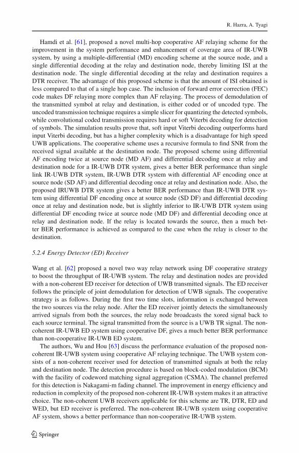
The BER performance of the non-coherent IR-UWB receivers in CM1 environment,expressed in terms of cooperative and non-cooperative schemes are vividly shown inFig. 9a–d. The inference drawn from the simulation results state that for all cooperativeand non-cooperative schemes, at a BER of 10−3, DTR receiver outperforms TR receiverby a margin of 4–6 dB. Hence it can be concluded from the simulations that, DTR and TRreceiver gives the best and worst performance among all the non-coherent IR-UWB ACreceivers, using cooperative relay and non-cooperative strategies. The reason being, TR sys-tem suffers a loss of more than 3 dB, due to the wastage of power in transmitting a referencepulse along with modulated information pulse over a frame. This problem is mitigated usinga DTR system, which transmits only differential data over the present frame by modulat-ing the information symbol with the differential data obtained over the previous frame. ACreceivers require long analog delay line for correlating the received signal with its delayedform, thereby leading to complexity issues. Hence, AC receivers are replaced by novel low
123
Cooperative Impulse Radio Ultra-Wideband Communication
Fig. 9 BER performance comparisons of non-coherent IR-UWB receivers using various cooperative and non-cooperative strategies in CM1 channel. a Cooperative DF strategy, b cooperative DTF strategy, c cooperativeAF strategy, d non-cooperative or single link strategy
complexity ED receivers, even though it comes at the cost of inferior BER performance. It isobserved from the simulation results that for both cooperative and non-cooperative scheme,ED-OOK receiver gives a performance gain of 2 dB over TR receiver, and is slightly inferiorto that of DTR receiver. Since ED-OOK receiver gives the least complexity, it is preferredover the other non-coherent IR-UWB receivers, despite its performance inferiority comparedto DTR receiver in both cooperative and non-cooperative scenario.
Further, the conclusion obtained from the simulation results prove that at a BER of 10−3,IR-UWB AC and ED receivers using cooperative DF scheme, outperforms the other coop-erative relay i.e. DTF, AF and non-cooperative schemes. Hence, the use of cooperative relaytechnology not only improves the QoS, but also coverage area and BER performance, overnon-cooperative i.e. single link technology.
7 Conclusion
The paper gives a brief understanding of all the possible coherent and non-coherent IR-UWBreceivers. It also outlines the working principle, basic results, advantages and disadvantages
123

R. Hazra, A. Tyagi
related to all these IR-UWB receivers. The major problems faced by coherent IR-UWBRAKE receivers are, requirement of accurate channel estimation and complexity due tothe use of correlators. So, we resort to non-coherent IR-UWB receivers. Non-coherent IR-UWB receivers do not require channel estimation and are attractive because of its simplicity,even though they are inferior to coherent IR-UWB receivers in performance. Among thevarious non-coherent IR-UWB AC receivers discussed, TR, TRPC and DTR, work by initiallyautocorrelating the received signal. The resultant autocorrelated signal is then integrated, andfinally the information symbol is recovered from the integrator output using decision criteria.AC receivers require long analog delay lines for performing correlation operation hence,leading to complexity problems. The complexity issues faced by AC receivers are resolvedusing low complexity ED receiver, which works by squaring the received signal, followedby integration process, in order to recover the original symbol.
Cooperative communication is a new technology where information is transmitted fromthe source to the destination through the intermediate nodes also called the relay nodes. Therelay nodes are fitted between the source and destination in order to improve the systemperformance and QoS. In a dual hop cooperative scheme, information is initially transmittedfrom the source to the relay in the first time slot where it is detected, decoded or amplifiedby the receiver depending upon the cooperative strategy used at the relay. The various fixedcooperative strategies used for UWB relay communication are AF, DF and DTF. Also a directsignal from the source node is sent to the destination node during the same time slot. The relaynode then forwards the information to the destination node in the second time slot. At the des-tination node, the combined received signal from the source node and relay node is extractedusing a receiver. Once the received signal is known at the destination, SNR can be evaluated.If SNR is known, BER performance can also be evaluated using MGF or CF method.
The paper not only gives a concise understanding of all the possible research done bythe researchers in the field of cooperative and non-cooperative IR-UWB communication, butalso explores the novelty by introducing cooperative relay scheme in ED receivers. The paperalso gives an insight on the working principle and the performance evaluation of the variouscoherent and non-coherent IR-UWB detection systems, using different cooperative and non-cooperative strategies. From the review it can be concluded that, cooperative communicationprovides a better result using coherent IR-UWB systems, but it leads to complexity. So, weresort to non-coherent IR-UWB receivers.
Further the BER performance of all the non-coherent IR-UWB receivers using dual hopcooperative strategy is compared with non-cooperative strategy. The inference obtained fromthe simulation results prove that, the use of cooperative DF technology with LDPC codes inUWB system is by far the best among all the cooperative relay techniques discussed in thepaper. Cooperative DF scheme, gives a SNR gain of 3, 4 and 6 dB at a BER of 10−3, over theother cooperative i.e. DTF, AF and non-cooperative schemes respectively. Even though thesimulation results prove the superiority of DTR receiver over ED receiver in terms of BERperformance using both cooperative and non-cooperative schemes, yet ED-OOK receiver ispreferred among all the non-coherent IR-UWB receivers because of its less complexity andlow power consumption. Hence it can be concluded by saying that, the combination of UWBtechnology and cooperative communication is a viable technology for improving the BERperformance, QoS and coverage area.
8 Future Work
From the survey done on IR-UWB cooperative communication, it can be concluded that, thefocus of research has been mostly on non cooperative IR-UWB communication using TR
123

Cooperative Impulse Radio Ultra-Wideband Communication
and DTR detection systems and not enough work has been carried out using ED and WEDdetectors. This could be a future direction for researchers in this area. The literature mostlyfocuses on cooperative IR-UWB relay communication for a single user. This can be furtherextended to multi-users. Another possible direction could be performance evaluation of IR-UWB cooperative relay communication system in presence of MAI and synchronizationerrors.
References
1. Win, M. Z., & Scholtz, R. A. (1998). Impulse radio: How it works. IEEE Communication Letters, 2(2),36–38. doi:10.1109/4234.660796.
2. Federal Communications Commission (FCC), Revision of part 15 of the commission’s rulesagainst regarding Ultra-Wideband Transmission Systems. First Report and Order, ET Docket 98-153, FCC 02-48, Adopted: Feb 2002, Release Apr 2002. http://www.ntia.doc.gov/fcc-filing/2000/ntia-comments-revision-part-15-commissions-regarding-ultrawideband-transmission-syst.
3. Porcino, D., & Hirt, W. (2003). Ultra-wideband radio technology: Potential and challenges ahead. IEEECommunications Magazine, 41(7), 66–74. doi:10.1109/MCOM.2003.1215641.
4. Aiello, G. R., & Rogerson, G. D. (2003). Ultra-wideband wireless systems. IEEE Microwave Magazine,4(2), 36–47. doi:10.1109/MMW.2003.1201597.
5. Wentzloff, D. D., Blazquez, R., Lee, F. S., Ginsburg, P., Powell, J., & Chandrakeshan, A. P. (2005). Systemdesign considerations for ultra-wideband communication. IEEE Communications Magazine, 43(8), 114–121. doi:10.1109/APS.2003.1217587.
6. Mohammad, S., & Sadough, S. (2009). A tutorial on ultra wideband modulation and detection schemes.http://www.faculties.sbu.ac.in/sadough/pdf/uwb_tutorial.pdf. Accessed Apr 2009.
7. Fernandes, J. R., & Wentzloff, D. (2010). Recent advances in IR-UWB transceivers: An overview. InProceedings of IEEE international symposium on circuits and systems (ISCAS) (pp. 3284–3287). doi:10.1109/ISCAS.2010.5537916.
8. Siriwongpairat, W. P., Su, W., Han, Z., & Liu, K.-J.-R. (2006). Employing cooperative diversity for per-formance enhancement in UWB communication systems. In Proceedings IEEE wireless communicationand networking conference (WCNC), vol. 4 (pp. 1854–1859). doi:10.1109/WCNC.2006.1696578.
9. Laneman, J. N., Tse, D. N. C., & Wornell, G. W. (2004). Cooperative diversity in wireless networks:Efficient protocols and outage behavior. IEEE Transactions on Information Theory, 50(12), 3062–3080.doi:10.1109/TIT.2004.838089.
10. Laneman, J. N. (2002). Cooperative diversity in wireless networks: Algorithm and architectures. Ph.D dis-sertation, MIT, Cambridge, MA, 2002. http://citeseerx.ist.psu.edu/viewdoc/download?doi=10.1.1.129.305&rep=rep1&type=pdf.
11. Sendonaris, A., Erkip, E., & Aazhang, B. (2003). User cooperation diversity-part I: System description.IEEE Transactions on Communications, 51(11), 1927–1938. doi:10.1109/TCOMM.2003.818096.
12. Jamshidi, A., & Nasiri-Kenari, M. (2008). Performance analysis of transmitter-side cooperation-receiver-side-relaying schemes for heterogeneous sensor networks. IEEE Transactions on Vehicular Technology,57(3), 1548–1563. doi:10.1109/TVT.2007.909299.
13. Van Der Meulen, E. C. (1971). Three-terminal communication channels. Advances in Applied Probability,3(1), 120–154.
14. Cover, T. M., & El Gamal, A. A. (1979). Capacity theorems for the relay channel. IEEE Transactions onInformation Theory, 25(5), 572–584. doi:10.1109/TIT.1979.1056084.
15. Katiyar, H., Rastogi, A., & Agarwal, R. (2011). Cooperative communication: A review. IETE TechnicalReview, 28(5), 409–417. doi:10.4103/0256-4602.85974.
16. Khan, M. G., Nordberg, J., & Claesson, I. (2008). Performance evaluation of RAKE receiver for low datarate UWB systems using multipath channels for industrial environments. Research Report, BlekingeInstitute of Technology. http://www.bth.se/fou/forskinfo.nsf/0/ee5efbf0dad21be4c125746d004ee979/file/UWBResearchReport1_MGK.pdf.
17. Win, M. Z., & Scholtz, R. A. (2002). Characterizati on of ultra-wide bandwidth wireless indoor channels:A communication-theoretic view. IEEE Journal on Selected Areas in Communication, 20(9), 1613–1627.doi:10.1109/JSAC.2002.805031.
18. Cassioli, D., Win, M. Z., Vatalaro, F., & Molisch, A. F. (2002). Performance of low- complexity RAKEreception in a realistic UWB channel. Proceedings of IEEE International Conference on Communications,ICC, 2(2), 763–767. doi:10.1109/ICC.2002.996958.
123

R. Hazra, A. Tyagi
19. Amico, A. A. D., Mengali, U., & Taponecco, L. (2004). Performance comparisons between two signalingformats for UWB communications. In Proceedings of IEEE international conference on communications,ICC, vol. 6 (pp. 3404–3408). doi:10.1109/ICC.2004.1313176.
20. Romme, J., & Witrisal, K. (2006). Transmitted-reference UWB systems using weighted autocorrelationreceivers. IEEE Transactions on Microwave Theory and Technology, 54(4), 1754–1761. doi:10.1109/TMTT.2006.872061.
21. Luo, X., & Gian nakis, G. B. (2006). Achievable rates of transmitted-reference ultra-wideband radio WithPPM. IEEE Transactions on Communications, 54(9), 1536–1541. doi:10.1109/TCOMM.2006.881203.
22. Amico, A. A. D., & Mengali, U. (2005). GLRT receivers for UWB systems. IEEE CommunicationsLetters. doi:10.1109/LCOMM.2005.06032.
23. Chan, Y.-L., & Scholtz, R. A. (2003). Optimal and suboptimal receivers for ultra-wideband transmittedreference systems. In Proceedings Of global telecommunications conference, Globecom, vol. 2 (pp. 759–763). doi:10.1109/GLOCOM.2003.1258340.
24. Franz, S., & Mitra, U. (2003). On optimal data detection for UWB transmitted reference systems. InProceedings of IEEE global telecommunications conference, Globecom, vol. 2 (pp. 744–748). doi:10.1109/GLOCOM.2003.1258337.
25. He, S., & Dong, X. (2010). Implementation of a low complexity UWB transmitted reference pulse clustersystem. In Proceedings of 2010 IEEE 72nd vehicular technology conference, (VTC Fall) (pp. 1–5). doi:10.1109/VETECF.2010.5594332.
26. El Abri, K. B. H., & Bouallegue, A. (2012). A new UWB system based on a frequency domain trans-formation of the received signal. International Journal of Wireless and Mobile Networks (IJWMN), 4(2),175–179.
27. Amico, A. A. D., & Taponecco, L. (2006). A differential receiver for UWB systems. IEEE Transactionson Wireless Communications, 5(7), 1601–1605. doi:10.1109/TWC.2006.1673067.
28. Khani, H., & Azmi, K. (2008). Performance analysis of a high data rate UWB DTR system in densemultipath channels. Progress in Electromagnetics Research B, 5, 119–131.
29. Sahin, M. E., Guvenc, I., & Arslan, H. (2005). Optimization of energy detector receivers for UWBsystems. In Proceedings of 2005 IEEE 61st vehicular technology conference (VTC Spring), vol. 2 (pp.1386–1390). doi:10.1109/VETECS.2005.1543536.
30. Jianjun, Wu, Qinglin, L., & Hiage, X. (2008). Analysis of weighted non-coherent receiver for UWB-OOKsignal in multipath channels. Journal of Electronics (China), 25(1), 32–38.
31. Wang, F., Tian, Z., & Sandler, B. M. (2011). Weighted energy detection for noncoherent ultra-widebandreceiver design. IEEE Transactions on Wireless Communications, 10(2), 710–720. doi:10.1109/TWC.2010.120310.101390.
32. Ji, S. A., Lee, S. J., & Kim, J. S. (2012). Simplified structure of weighted energy detector for UWB-IRsystems. IEEE Electronic Letters, 48(1), 48–50. doi:10.1049/el2011.2755.
33. Jianjun, Wu, Qinglin, L., & Hiage, X. (2006). Weighted noncoherent receivers for UWB PPM signals.IEEE Communications Letters, 10(9), 655–657. doi:10.1109/LCOMM.2006.1714535.
34. Qing-Hua, S., Xuan-li, X., Di, L., & Xin, Q. (2010). Performance analysis of cooperative ultra-widebandcommunication system. In Proceedings of 2010 IEEE international conference on communications andmobile computing (CMC), vol. 2 (pp. 217–220). doi:10.1109/CMC.2010.249.
35. Lee, Y., & Tsai, M.-H. (2009). Performance of decode-and-forward cooperative communications overNakagami-m fading channels. IEEE Transactions on Vehicular Technology, 58(3), 1218–1228. doi:10.1109/TVT.2008.928907.
36. Bai, Z., & Xu, Y. (2012). MGF based performance analysis of dual-hop regenerative relaying IR-UWBsystems. International Journal of Electronics and Communication (AEU), Elsevier, 66(8), 641–646.doi:10.1016/j.aeue.2011.12.003.
37. Yuan, J., Li, Y., & Chu, L. (2010). Differential modulation and relay selection with detect-and-forwardcooperative relaying. IEEE Transactions on Vehicular Technology, 59(1), 261–268. doi:10.1109/TVT.2009.2031802.
38. Aziz, A. A., Iwanami, Y., & Okamato, E. (2009). Efficient combining technique with a low complexitydetect-and-forward relay for cooperative diversity scheme. In Proceedings of IEEE region 10 conference.TENCON, vol. 9 (pp. 1–6). doi:10.1109/TENCON.2009.5396130.
39. Maichalernnukul, K., Kaiser, T., & Zheng, F. (2009). On the performance of coherent and noncoherentUWB detection systems using a relay with multiple antennas. IEEE Transactions on Wireless Communi-cations, 8(7), 3407–3414. doi:10.1109/TWC.2009.080830.
40. Saleh, A. A. M., & Venezuela, R. (1987). A statistical model for indoor multipath propagation. IEEEJournal on Selected Areas in Communications, 5(2), 128–137. doi:10.1109/JSAC.1987.1146527.
123

Cooperative Impulse Radio Ultra-Wideband Communication
41. Maichalernnukul, K., Kaiser, T., & Feng, Z. (2009). Performance investigation of a UWB relay systemusing multiple relays with multiple antennas in IEEE 802.15.3a channel. In Proceedings of IEEE 69thvehicular technology conference, VTC, Spring (pp. 1–6). doi:10.1109/VETECS.2009.5073792.
42. Shirazi, G. N., Kong, P. Y., & Tham, C. K. (2008). A low-overhead cooperative retransmission schemefor IR-UWB networks. Research Letters in Communication. doi:10.1109/ICUWB.2008.4653387.
43. Shirazi, G. N., Kong, P. Y., & Tham, C. K. (2010). Optimal cooperative relaying schemes in IR-UWBnetworks. IEEE Transactions on Mobile Computing, 9(7), 969–981. doi:10.1109/TMC.2010.43.
44. Abou-Rjeily, C. (2013). A symbol-by-symbol cooperative diversity scheme for relay-assisted UWB com-munications with PPM. IEEE Journal on Selected Areas in Communication, 31(8), 1436–1445. doi:10.1109/JSAC.2013.130808.
45. Abou-Rjeily, C., Daniele, N., & Belfiore, J. C. (2006). On the decode-and-forward cooperative diversitywith coherent and non-coherent UWB systems. In Proceedings of IEEE 2006 international conferenceon ultra-wideband (pp. 435–440). doi:10.1109/ICU.2006.281589
46. Zeinalpour-Yazdi, Z., Nasiri-Kenari, M., & Aazhang, B. (2012). Performance of UWB linked relaynetwork with time-reversed transmission in the presence of channel estimation error. IEEE Transactionson Wireless Communications, 11(8), 2958–2969. doi:10.1109/TWC.2012.061912.111866.
47. Bai, Z., Xu, Y., Shen, B., Kwak, K. S. & Yuan, D. (2011). Performance analysis of dual-hop UWBsystem with non-regenerative relaying scheme. In Proceedings of 13th IEEE international conference onadvanced communication technology (ICACT) (pp. 1221–1225).
48. Xu, Y., Bai, Z., & Kwak, K. S. (2011). On the performance of dual-hop regenerative cooperative relayingof IR-UWB System. In Proceedings of 11th IEEE international symposium on communications andinformation technologies (ISCIT) (pp. 323–327). doi:10.1109/ISCIT.2011.6089758.
49. Xu, Y., Bai, Z., Yang, X., Wang, A. L., & Kwak, K. (2011). Closed-form BER analysis of dual-hop non-regenerative IR-UWB system over multipath channels. In Proceedings of 2011 IEEE13th internationalconference on communication technology (ICCT) (pp. 126–130). doi:10.1109/ICCT.2011.6157847.
50. Zeinalpour Yazdi, Z., & Nasiri Kenari, M. (2010). Bit error probability analysis of UWB communicationswith a relay node. IEEE Transactions on Wireless Communications, 9(2), 802–813. doi:10.1109/TWC.2010.02.090383.
51. Maichalernnukul, K., Feng, Z., & Kaiser, T. (2010). Dual-hop UWB transmissions using a multipleantenna relay with antenna selection versus single-antenna relay selection. In Proceedings of 2010 IEEEinternational ITG conference on source and channel coding (SCC) (pp. 1–6).
52. Yang, Y., Wang, D., Li, M., & Song, Y. (2010). A relay selection scheme for IR-UWB networks based ondistance information. In Proceedings of 2010 IEEE international conference on information theory andinformation security (ICITIS) (pp. 1046–1049). doi:10.1109/ICITIS.2010.5689728.
53. Pan, G., Ekici, E., & Feng, Q. (2012). Performance analysis of cooperative time hopping UWB systemswith multi-user interference. IEEE Transactions on Wireless Communications, 11(6), 1969–1975. doi:10.1109/TWC.2012.040412.102318.
54. Maichalernnukul, K., Kaiser, T., & Feng, Z. (2011). Performance of ultrawideband cooperative relaysystems in the presence of narrowband interference. In Proceedings of 2011 IEEE international conferenceon ultra-wideband (ICUWB) (pp. 405–409). doi:10.1109/ICUWB.2011.6058874
55. Feng, W., Chengqi, X., & Yan, Z. (2009). The TR-UWB receiver based on spatial diversity. Journal ofElectronics (China), 26(5), 623–630.
56. Dong, X., & Dong, X. (2010). Bi-directional cooperative relays for transmitted reference pulse clusterUWB systems. In Proceedings of 2010 IEEE global telecommunications conference. Globecom (pp. 1–5).doi:10.1109/GLOCOM.2010.5683989.
57. Gao, H., Su, X., Lv, T., Wang, T., & Wang, Z. (2011). Physical-layer network coding aided two wayrelay for transmitted-reference UWB networks. In Proceedings of 2011 IEEE global telecommunicationsconference, Globecom (pp. 1-6). doi:10.1109/GLOCOM.2011.6133672.
58. Mondelli, M., Zhou, Q., Ma, X., & Lottici, V. (2012). A cooperative approach for amplify- and-forwarddifferential transmitted reference IR-UWB relay systems. In Proceedings of 2012 IEEE internationalconference on acoustics, speech and signal processing (ICASSP) (pp. 2905–2908). doi:10.1109/ICASSP.2012.6288524.
59. Wu, T. M., & Hou, Y. F. (2011). Performance analysis of cooperative communication in the UWB differ-ential transmitted reference system. In Proceedings of 2011 IEEE 73rd vehicular technology conference(VTC Spring) (pp. 1–5). doi:10.1109/VETECS.2011.5956239.
60. Hamdi, M., Mietzner, J., & Schober, R. (2010). Double-differential encoding for dual-hop amplify-and-forward relaying in IR UWB systems. In Proceedings of 2010 IEEE 71st vehicular technology conference(VTC Spring) (pp. 1–5). doi:10.1109/VETECS.2010.5493862
123

R. Hazra, A. Tyagi
61. Hamdi, M., Mietzner, J., & Schober, R. (2011). Multiple-differential encoding for multi-hop amplify-and-forward relaying in IR-UWB systems. IEEE Transactions on Wireless Communications, 10(8), 2577–2591. doi:10.1109/TWC.2011.060811.100582.
62. Wang, Z., Lv, T., Gao, H., & Li, Y. (2011). A novel two-way relay UWB network with joint non-coherentdetection in multipath. In Proceedings of 2011 IEEE 73rd vehicular technology conference (VTC Spring)(pp. 1–5). doi:10.1109/VETECS.2011.5956243.
63. Wu, T. S., & Hou, Y. F. (2012). Noncoherent UWB with block coded modulation in cooperative commu-nications systems. In Proceedings of 2012 IEEE 16th international symposium on consumer electronics(ISCE) (pp. 1–4). doi:10.1109/ISCE.2012.6241751.
Author Biographies
Ranjay Hazra is currently doing his Ph.D. under the guidance ofDr. Anshul Tyagi in Department of Electronics and CommunicationEngineering, Indian Institute of Technology Roorkee. His researcharea includes IR-UWB Communication, OFDM Systems and Cogni-tive Radio.
Anshul Tyagi received his B.Tech (Electrical Engineering) and Ph.D.(Communication Engineering) degrees from Indian Institute of Tech-nology Delhi in 1997 and 2006, respectively. Currently he is workingas an Assistant Professor in the Department of E&CE in Indian Instituteof Technology Roorkee. His research area includes Digital Communi-cations, Error Control Coding and UWB Communications.
123
![on coherent and non-coherent receiver structures for impulse ...835942/...[1], [2]. OFDM is a modulation scheme that exploits frequency diversity in-herent in a wideband channel to](https://static.fdocuments.us/doc/165x107/60f94434a93db050ce4bdf66/on-coherent-and-non-coherent-receiver-structures-for-impulse-835942-1.jpg)