
Cooling Systems for the New 201.25 MHz Final Power...
3
COOLING SYSTEMS FOR THE NEW 201.25 MHz FINAL POWER AMPLIFIERS AT LOS ALAMOS NEUTRON SCIENCE CENTER (LANSCE)* W.C. Barkley # , C.E. Buechler, J.T.M. Lyles, A.C. Naranjo, LANL, Los Alamos, NM 87544, USA D. Baca, R.E. Bratton, Compa Industries, Los Alamos, NM 87544, USA Abstract Two new 201.25 MHz RF Final Power Amplifiers (FPAs) have been designed, assembled, installed and successfully tested at the Los Alamos Neutron Science Center (LANSCE), in Module 2 of the Drift Tube Linac (DTL). These production units were fabricated at Continental Electronics Corporation. In this paper, we summarize the FPA air and water cooling requirements and cooling systems [1]. Description of Systems Figure 1 shows a CAD model of the FPA installation. Figure 1: Model of FPA Installation. Three separate water systems were required to fully cool each FPA and its auxiliary components. Two existing systems were modified and a new system was installed to meet the cooling requirements. A deionized water system (A01), cools the two power-combined FPAs and Intermediate Power Amplifier (IPA) directly. A chilled water system (A05), cools the RF reference source for the LANSCE accelerator and ignitrons in each of the four capacitor rooms. A treated water system (A06), cools the solid state driver amplifier (Rack 5), FPA and IPA water loads. Flow requirements for the three water systems were developed for combined amplifier power, 3.4 MW at 13% duty factor or 442 kW each [2]. In addition, air cooling was implemented where water cooling was not practical. The A01 System The A01 system is an existing deionized water system that served the obsolete power amplifier that was previously located at Module 2 of the DTL. Centrifugal pumps, located in an adjacent mechanical room, deliver 88 psi, 1,250 gpm for the four DTL modules. One pump operates while the other serves as a backup. Adaptation of this water system consists of demolishing the existing plumbing at the module and installing the new plumbing as depicted in Fig. 2. Deionized water is required to eliminate the potential electrical path to ground in an ionized system. The A01 system is adapted to cool both FPAs and the IPA which is not shown in Fig. 2. Figure 2: A01 Water System Adapted to the FPA Installation. Note that the gray-colored piping and associated components in Fig. 2 are the distribution hardware for the A01 water system, and the brown colored piping is the 3 1/8 inch coax RF transmission lines. The A01 piping is mounted to the legs of the platform, and the legs of the platform are anchored to the concrete. Figure 3: Side View of A01 Water System Mounted to Platform. *Work supported by the United States Department of Energy, National Nuclear Security Agency, under contract DE-AC52-06NA25396 #b[email protected] Proceedings of IPAC2015, Richmond, VA, USA WEPTY084 7: Accelerator Technology T08 - RF Power Sources ISBN 978-3-95450-168-7 3479 Copyright © 2015 CC-BY-3.0 and by the respective authors
Transcript of Cooling Systems for the New 201.25 MHz Final Power...

COOLING SYSTEMS FOR THE NEW 201.25 MHz FINAL POWER AMPLIFIERS AT LOS ALAMOS NEUTRON SCIENCE CENTER
(LANSCE)*
W.C. Barkley#, C.E. Buechler, J.T.M. Lyles, A.C. Naranjo, LANL, Los Alamos, NM 87544, USA D. Baca, R.E. Bratton, Compa Industries, Los Alamos, NM 87544, USA
Abstract Two new 201.25 MHz RF Final Power Amplifiers
(FPAs) have been designed, assembled, installed and successfully tested at the Los Alamos Neutron Science Center (LANSCE), in Module 2 of the Drift Tube Linac (DTL). These production units were fabricated at Continental Electronics Corporation. In this paper, we summarize the FPA air and water cooling requirements and cooling systems [1]. Description of Systems
Figure 1 shows a CAD model of the FPA installation.
Figure 1: Model of FPA Installation.
Three separate water systems were required to fully
cool each FPA and its auxiliary components. Two existing systems were modified and a new system was installed to meet the cooling requirements. A deionized water system (A01), cools the two power-combined FPAs and Intermediate Power Amplifier (IPA) directly. A chilled water system (A05), cools the RF reference source for the LANSCE accelerator and ignitrons in each of the four capacitor rooms. A treated water system (A06), cools the solid state driver amplifier (Rack 5), FPA and IPA water loads.
Flow requirements for the three water systems were developed for combined amplifier power, 3.4 MW at 13% duty factor or 442 kW each [2]. In addition, air cooling was implemented where water cooling was not practical. The A01 System
The A01 system is an existing deionized water system that served the obsolete power amplifier that was
previously located at Module 2 of the DTL. Centrifugal pumps, located in an adjacent mechanical room, deliver 88 psi, 1,250 gpm for the four DTL modules. One pump operates while the other serves as a backup. Adaptation of this water system consists of demolishing the existing plumbing at the module and installing the new plumbing as depicted in Fig. 2. Deionized water is required to eliminate the potential electrical path to ground in an ionized system. The A01 system is adapted to cool both FPAs and the IPA which is not shown in Fig. 2.
Figure 2: A01 Water System Adapted to the FPA Installation.
Note that the gray-colored piping and associated components in Fig. 2 are the distribution hardware for the A01 water system, and the brown colored piping is the 3 1/8 inch coax RF transmission lines. The A01 piping is mounted to the legs of the platform, and the legs of the platform are anchored to the concrete.
Figure 3: Side View of A01 Water System Mounted to Platform.
*Work supported by the United States Department of Energy, National Nuclear Security Agency, under contract DE-AC52-06NA25396 #[email protected]
Proceedings of IPAC2015, Richmond, VA, USA WEPTY084
7: Accelerator TechnologyT08 - RF Power Sources
ISBN 978-3-95450-168-73479 Co
pyrig
ht©
2015
CC-B
Y-3.
0an
dby
ther
espe
ctiv
eaut
hors
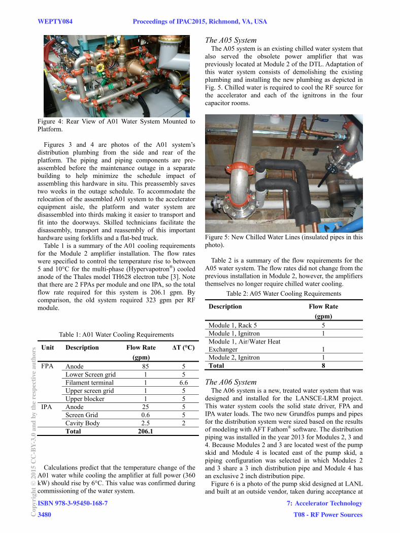
Figure 4: Rear View of A01 Water System Mounted to Platform.
Figures 3 and 4 are photos of the A01 system’s
distribution plumbing from the side and rear of the platform. The piping and piping components are pre-assembled before the maintenance outage in a separate building to help minimize the schedule impact of assembling this hardware in situ. This preassembly saves two weeks in the outage schedule. To accommodate the relocation of the assembled A01 system to the accelerator equipment aisle, the platform and water system are disassembled into thirds making it easier to transport and fit into the doorways. Skilled technicians facilitate the disassembly, transport and reassembly of this important hardware using forklifts and a flat-bed truck.
Table 1 is a summary of the A01 cooling requirements for the Module 2 amplifier installation. The flow rates were specified to control the temperature rise to between 5 and 10°C for the multi-phase (Hypervapotron®) cooled anode of the Thales model TH628 electron tube [3]. Note that there are 2 FPAs per module and one IPA, so the total flow rate required for this system is 206.1 gpm. By comparison, the old system required 323 gpm per RF module.
Table 1: A01 Water Cooling Requirements
Unit Description Flow Rate
(gpm)
ΔT (°C)
FPA Anode 85 5 Lower Screen grid 1 5 Filament terminal 1 6.6 Upper screen grid 1 5 Upper blocker 1 5
IPA Anode 25 5 Screen Grid 0.6 5 Cavity Body 2.5 2
Total 206.1
Calculations predict that the temperature change of the
A01 water while cooling the amplifier at full power (360 kW) should rise by 6°C. This value was confirmed during commissioning of the water system.
The A05 System The A05 system is an existing chilled water system that
also served the obsolete power amplifier that was previously located at Module 2 of the DTL. Adaptation of this water system consists of demolishing the existing plumbing and installing the new plumbing as depicted in Fig. 5. Chilled water is required to cool the RF source for the accelerator and each of the ignitrons in the four capacitor rooms.
Figure 5: New Chilled Water Lines (insulated pipes in this photo).
Table 2 is a summary of the flow requirements for the A05 water system. The flow rates did not change from the previous installation in Module 2, however, the amplifiers themselves no longer require chilled water cooling.
Table 2: A05 Water Cooling Requirements
Description Flow Rate
(gpm) Module 1, Rack 5 5 Module 1, Ignitron 1 Module 1, Air/Water Heat Exchanger 1 Module 2, Ignitron 1 Total 8
The A06 System
The A06 system is a new, treated water system that was designed and installed for the LANSCE-LRM project. This water system cools the solid state driver, FPA and IPA water loads. The two new Grundfos pumps and pipes for the distribution system were sized based on the results of modeling with AFT Fathom® software. The distribution piping was installed in the year 2013 for Modules 2, 3 and 4. Because Modules 2 and 3 are located west of the pump skid and Module 4 is located east of the pump skid, a piping configuration was selected in which Modules 2 and 3 share a 3 inch distribution pipe and Module 4 has an exclusive 2 inch distribution pipe.
Figure 6 is a photo of the pump skid designed at LANL and built at an outside vendor, taken during acceptance at
WEPTY084 Proceedings of IPAC2015, Richmond, VA, USA
ISBN 978-3-95450-168-73480Co
pyrig
ht©
2015
CC-B
Y-3.
0an
dby
ther
espe
ctiv
eaut
hors
7: Accelerator TechnologyT08 - RF Power Sources

the vendor. This pump skid is now installed at LANL and delivers 25±4°C treated water to the Module 2 installation. The pump motors are variable frequency, and an output pressure of 65 psi was selected to accommodate the entire system. A total flow rate of 120 gpm is the requirement once Modules 2, 3 and 4 are all upgraded. The plate-type heat exchanger, shown in blue in Fig. 6, is cooled by tower water supplied to the facility.
Figure 6: A06 Pump Skid (shown at fabrication facility).
Table 3 is a summary of the A06 cooling requirements for the Module 2 amplifier installation. The total flow rate required for this system is 40 gpm per module.
Table 3: A06 Water Cooling Requirements
Description Flow Rate
(gpm) IPA Water Load 15 FPA Water Load 20 Solid State Driver, Rack 5 5 Total 40
Air Cooling Air cooling for the amplifier consists of cooling both
the filament pipe and ceramics. The filament pipe is at the center of the amplifier, and the ceramics of the tube consist of an upper and lower ceramic as shown in Fig. 7.
The air flow requirement from the tube manufacturer, Thales, is shown in Table 4.
Table 4: Air Cooling Requirements
Description Flow Rate
(cfm) Upper Ceramic 177 Lower Ceramic 177 Filament Pipe 177 Total 531
Figure 7: Air Cooling Model (stripped down FPA).
To deliver the cooling air, blowers, manufactured by
Cincinnati Fan, were selected based on the flow rate requirement and the density of air at Los Alamos (7,000 ft. elevation). Model PB-14A was selected for the filament pipe and model PB-10A was selected for the ceramics. The model PB-14A (250 cfm) blower was connected directly to the filament pipe using a non-conductive hose and 3D printed plastic elbow. The model PB-10A (354 cfm) was connected by non-conductive hose to a 3D printed plastic manifold that splits the air flow into four flow paths; to cool the upper and lower ceramic on each side as shown in Fig. 7.
The cavity power dissipation from RF losses is estimated from Q measurements to be approximately 2% of the DC input power. For a single amplifier generating 1.7 MW of RF at 13% duty factor, this power is approximately 10 kW. Forced air transfers a portion of this heat, simultaneously cooling the ceramic seals of the tube. Conduction is enhanced by the copper construction of the various resonator cylinders, which affects the radiative cooling.
REFERENCES [1] Z. Chen, D. Baca, et. al., “Mechanical Design and
Fabrication of a New RF Power Amplifier for LANSCE”, PAC’11, New York, NY, pp. 1085-1087.
[2] J. Lyles, W. Barkley, et. al., “Results from the Installation of a New 201 MHz RF System at LANSCE,” 27th Linear Accelerator Conference, September, 2014, Geneva, Switzerland.
[3] J. Lyles, W. Barkley, J. Davis, et. al., “System Considerations for 201.25 MHz RF System for LANSCE”, NA/PAC’13, Pasadena, CA, pp. 963-965.
Proceedings of IPAC2015, Richmond, VA, USA WEPTY084
7: Accelerator TechnologyT08 - RF Power Sources
ISBN 978-3-95450-168-73481 Co
pyrig
ht©
2015
CC-B
Y-3.
0an
dby
ther
espe
ctiv
eaut
hors