COOLING SYSTEM - Nathi · PDF fileThe Purpose of Cooling System Prevent Overheating Excess...
55
COOLING SYSTEM
-
Upload
truongdiep -
Category
Documents
-
view
215 -
download
1
Transcript of COOLING SYSTEM - Nathi · PDF fileThe Purpose of Cooling System Prevent Overheating Excess...

COOLING SYSTEM

Introduction
I.C Engines at best can transform about 25-30 % of the chemicalenergy in to the fuel in to mechanical energy.
About 35 % of the heat generated is lost to the cooling mediumremainder being dissipated through exhaust and lubricating oil.
1/3 Heat to Useful Work
1/3 Heat to cooling System
1/3 Heat to exhaust system

Introduction
The Purpose of Cooling System
Prevent Overheating
Excess Heat generated in engine
Peak temperatures exceed melting point of metal
Regulate the most efficient Temperature
Regulate Temperature
Allow engine to warm up in cool weather
Maintain engine in optimum range.
Introduction
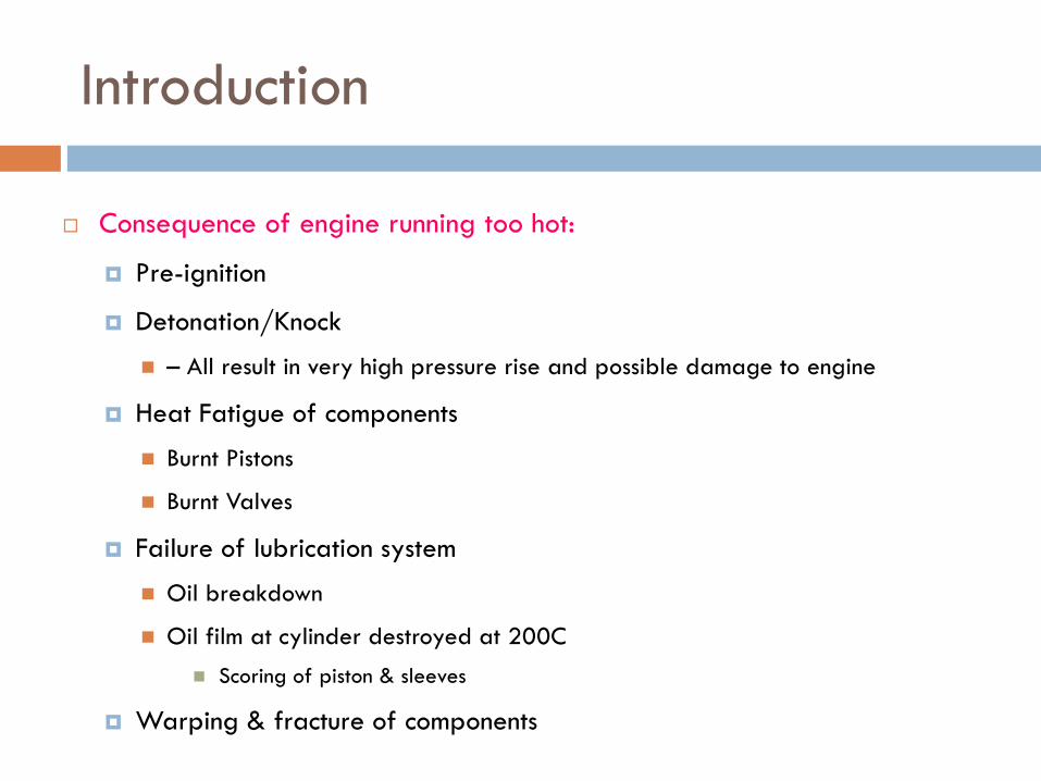
Consequence of engine running too hot:
Pre-ignition
Detonation/Knock
– All result in very high pressure rise and possible damage to engine
Heat Fatigue of components
Burnt Pistons
Burnt Valves
Failure of lubrication system
Oil breakdown
Oil film at cylinder destroyed at 200C Scoring of piston & sleeves
Warping & fracture of components

Introduction
Consequence of engine running too cold:
Unnecessary Wear
Poor Fuel Economy
Incomplete Combustion
Lower coolant Temperature More energy transferred out of cylinder
Energy from is wasted & not available for work (Power)
Promotes corrosive conditions in engine
Water of combustion reacts with sulfur oxides in exhaust Forms acids
Allows water & sludge to accumulate in crankcase
Over time, fuel diluting the oil will accumulate Normally lighter volatile fuel will evaporate as temp. rises

Critical engine components that need to be maintained at optimal designed temperature
Combustion chamber walls
Cylinder wall
Cylinder head
Piston
Exhaust valve
Spark plug
Gasoline / Diesel injector
Engine lubricants
Introduction

Centrifugal pump
Cooling fluid
Radiator
Fan
Thermostat
Cooling System components Function
Cooling fluid circulation
Heat transfer
Heat exchange with the ambient
Air through the radiator at low vehicle speed
Engine temperature stabilization
Cooling system

Expansion tank
Filler pressure cap
Passenger compartment radiator
Lubricant radiator
EGR cooling radiator (Diesel)
Fluid expansion and gas release
Cooling circuit pressure
Passenger compartment heating
Engine lubricant cooling
Exhaust gas cooling
Cooling System components Function
Cooling system

Heat transfer fluid Etilene glycol mixture in water (30 –60% concentration)
Water
High specific heat
Low viscosity
High heat of vaporization
Constant characteristics vs time and temperature
Etilene glycol
High thermal capacity
Low pressure drop
Low gas formation
Low freezing point
Cooling system

EG Weight Percent (%)
Freezing Point (deg F)
Freezing Point (deg C)
0 32 010 25 -420 20 -730 5 -1540 -10 -2350 -30 -3460 -55 -4870 -60 -5180 -50 -4590 -20 -29100 10 -12
Ethylene glycol freezing point vs concentration in water
Cooling system
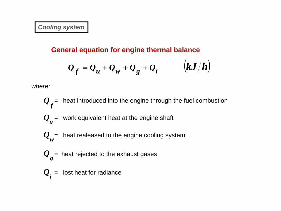
( )hkJigwuf QQQQQ +++=
fQ
uQ
wQ
gQ
iQ
= heat introduced into the engine through the fuel combustion
= work equivalent heat at the engine shaft
= heat realeased to the engine cooling system
= heat rejected to the exhaust gases
= lost heat for radiance
where:
General equation for engine thermal balance
Cooling system
Introduction
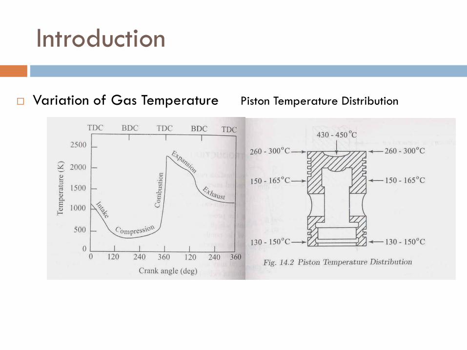
Variation of Gas Temperature Piston Temperature Distribution

Introduction
Heat Transfer As a result of combustion, high temperature are produced, inside
the engine cylinder
Considerable heat flow from the gases to the surrounding metalwalls
Shearing of the oil film
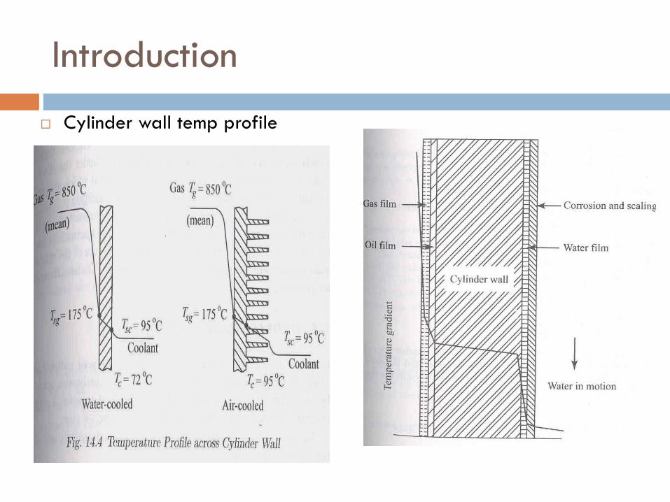
Heat transfer from gases to the cylinder walls may occurpredominantly by Convection & Radiation
Heat transfer through the cylinder wall occurs only by conduction
The temperature profiles across the cylinder barrel wall For water cooled engine
Air cooled engine
Introduction
Cylinder wall temp profile

Parameters Affecting Engine Heat Transfer
Engine heat transfer depends upon many parameters, unless the effect ofthese parameters is known, the design of a proper cooling system will bedifficult.
Fuel-Air Ratio
A change in fuel-air ratio will change the temperature of the cylinder gases andaffect the flame speed.
Spark Advance
More or less spark advance from the optimum value will result in increased heatrejection to the cooling system
Pre-ignition and knocking
Engine output
Engines which are designed for high M.E.P or high piston speeds, heat rejection willbe less
Cylinder wall temperature

Characteristics of an efficient cooling system
The two main characteristics desired of an efficientcooling system It should capable of removing about 30 % of the heat
generated in the combustion chamber while maintaining theoptimum temperature of the engine under all operatingconditions of the engine
It should remove heat at a faster rate when engine is hot.However during starting of the engine the cooling should beminimum, so that the working parts of the engine reach theiroperating temperatures in a short time

Types of cooling System
There are two types of system in general Liquid or indirect cooling system
Air or direct cooling system
Liquid cooling system Mainly water is used and made to circulate through the cooling
jackets provided around the cylinder, cylinder head, valve portsand seats where it extracts most of the heat
The heat transferred from the cylinder wall and other parts byconvection and conduction
The heat from liquid in turn is transferred to air. Hence it is calledthe indirect cooling system

Methods of water-cooling System
Water cooling can be carried out by any one of the
following five methods
Direct or non return system
Thermosyphon system
Forced circulation cooling system
Evaporation cooling system
Pressure cooling system

Direct or Non return System
This system is useful for large installations where plenty ofwater is available.
The water from a storage tank is directly supplied through aninlet valve to the engine cooling water jacket
The hot water is not cooled for reuse but simply discharged.

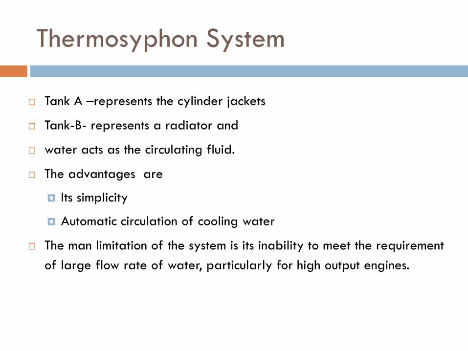
Thermosyphon System
Heat is supplied to the fluid in the tank A
Because of relatively lower density, the hot fluid travels up
Its place being taken up by comparatively cold fluid from the Tank Bthrough the pipe p2
The hot fluid flows through the pipe P1 to the tank B where it gets cooled
The fluid circulates through the system in the form of convection current
Thermosyphon System
Tank A –represents the cylinder jackets
Tank-B- represents a radiator and
water acts as the circulating fluid.
The advantages are
Its simplicity
Automatic circulation of cooling water
The man limitation of the system is its inability to meet the requirementof large flow rate of water, particularly for high output engines.

Forced circulation Cooling System
This system is added in a large number of Automobiles.
Here the flow of water from radiators to water jackets is byconvection assisted by a pump

Forced circulation Cooling System
Water or coolant is circulated with through jackets around the parts ofthe engine to be cooled is kept in motion by a centrifugal pump which isdriven by the engine
The water is passed through the radiator where it is cooled by theforward motion of the vehicle
A thermostat is used to control the water temperature required forcooling
This system consists of 4 components
Radiator water pump
Fan thermostat

Basic Schematic Layout
Radiator
WaterPump
Engine Block &Cylinder head Water Jacket
Thermo-stat
Heater Control
Cab heatexchanger
Fan

Parts of Engine Cooling System

Cooling System Construction
Radiator
Fan
Water Pump
Top Hose
Thermostat
Radiator Cap
Engine Block & Water Jacket

Cold Engine
When an engine is cold, thethermostat is cold. Coolant flowis through the bypass hose andthe water jackets. This allows theengine to warm up evenly.

Warm Engine
The thermostat opens whenthe engine warms up. Thisallows coolant to circulatethrough the radiator andthe water jackets.

Water jackets
Defined as the open space within in the cylinder block andcylinder head where coolant flows
Water jackets are designed to allow coolant flow to the rightspots flow so that maximum cooling can be obtained

Water Pump
The purpose
Is to circulate the water through the cooling system
Located on the front part of the engine
In most of the vehicles it is driven by a belt is attached to the crankshaft
As the crankshaft turns the fan belt turns

31
The water pump provides circulation of the engine coolant(antifreeze) through the cooling system: it pushes the coolantthrough the passages (water jackets) in the engine cylinder blockand cylinder head and then out into the radiator. The hot coolantpasses through the radiator where it cools down and then returnsback to the engine.
Centrifugal pump is the most used:it is a rotodynamic pumpthat uses a rotating impeller to increase the pressure and flow rateof a fluid. The fluid enters the pump impeller along or near to therotating axis and is accelerated by the impeller, flowing radiallyoutward or axially into a diffuser or volute chamber, from where itexits into the downstream piping system.
A water pump is usually driven by the engine through the drivingbelt and only sometimes by a timing belt. A water pump consists ofthe housing with the shaft rotating on the bearing pressed inside.At the outer side there is a pulley mounted on the shaft. At theinner side there is a seal to keep the coolant from leaking out andthe impeller.
Cooling system

• Impeller diameter (∅ = 60 - 75 mm)
• Impeller height (h = 12 - 20 mm)
• Paddles number and design (z = 5 - 10)
• Axial and radial impeller clearance
• Drive ratio
engine
pump
nn
=τ = 1.3 - 1.6
Main design characteristics
Cooling system
32

Thermostat
One of the most important parts of the cooling system
Purpose
Is to keep the engine coolant at most efficient temperature
The thermostat is used to bringthe coolant temperature up tooperating as quickly aspossible
It is designed to sense thetemperature of the coolant

Thermostat

35
Target - In internal combustion engines a thermostat is used to maintain the engine at itsoptimum operating temperature by regulating the flow of coolant to the external air cooledradiator. It must balance the heat rejected from the engine to the coolant and the heat rejectedfrom the radiator to the ambient in any operating vehicle mode.
This type of thermostat operates mechanically: it makes use of a wax pellet inside a sealedchamber. The wax is solid at low temperatures but as the engine heats up the wax melts andexpands. The sealed chamber has an expansion provision that operates a rod which opens avalve when the operating temperature is exceeded. The operating temperature is fixed, but isdetermined by the specific composition of the wax, so thermostats of this type are available tomaintain different temperatures, typically in the range of 70 to 90°C. Modern engines run hot,that is, over 80°C, in order to run more efficiently and to reduce the emission of pollutants.Most thermostats have a small bypass hole to vent any gas that might get into the system, e.g.,air introduced during coolant replacement, which also allows a small flow of coolant past thethermostat when it is closed. This bypass flow ensures that the thermostat experiences thetemperature change in the coolant as the engine heats up; without it a stagnant region ofcoolant around the thermostat could shield it from temperature changes in the coolant adjacentto the combustion chambers and cylinder bores.
Wax thermostatic elements permit the transforming of thermal energy into mechanical energy.Their working principle is based on the large increase in the thermal expansion of waxes whenthey pass from the solid to the liquid state
Cooling system

Radiator
Purpose Is to allow fresh air to reduce the temperature of the coolant
As the coolant passes through the tubes air is forcedaround the tube
This causes a transfer of heat from the hot coolant to thecooler air. This is called Heat exchanged
In this case, heat is exchanged from the liquid coolant toair. This is called a liquid-to air heat exchanger

Radiator
Coolant flows through the air fins The fins and tubes are cooled core

Radiator Parts
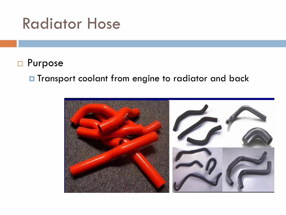
Radiator Hose
Purpose Transport coolant from engine to radiator and back
Radiator pressure cap
Pressure caps are designed to
Increase the pressure on the cooing system
Reduce cavitations
Protecting the radiator hose
Prevent or reduce surging
It is important to put pressure on the cooling system.Radiator pressure caps are typically near 15 psi
As the pressure increases the boiling point of the coolantalso increases (about 3 degrees for each 1 psi increase

Pressure Cap

Pressure cap

Pressure cap

Expansion tank

Expansion tank

Fan

Electric Fan Relay

Coolant Temperature Indicator

Coolant Temperature Indicator

Types of Coolant

Coolant

Coolant

Coolant

Anti-freeze
IAT: inorganic additive technology
OAT: organic acid technology
HOAT: hybrid organic acid technology
Extended and conventional anti-freezes cannot bemixed
EG: ethylene glycol
PG: propylene glycol

Anti-freeze
Maximum concentration: 67% anti-freeze Minimum concentration: 50% for corrosion
prevention Pure anti-freeze has higher viscosity and does not
flow well Does not transfer heat well