Cooler Mounted Bottle Fillers - Murdock Mfg - BF11-BF12.pdf · Cooler Mounted Bottle Fillers...
19
COMPLIES WITH Member of Date: 12/11/18 Murdock™ assumes no responsibility for use of void or superseded data. © Copyright Murdock Mfg., City of Industry, CA Member of Morris Group International. Please visit www.murdockmfg.com for most current specifications. INSTALLATION/MAINTENANCE INSTRUCTIONS Cooler Mounted Bottle Fillers MURDOCK 15125 Proctor Ave. City of Industry, CA 91746 U.S.A. Phone 800-591-9360 626-336-4561 Fax 626-855-4894 www.murdockmfg.com Federal Public Law 111-380 (No Lead) BF11 & BF12 Bottle Filler Series TABLE OF CONTENTS Dimensional Data/Rough-Ins ................................................ 2 .............................................. 3 Prior to Installation Information .................................................. 4 Push-In Fitting Installation ......................................... 5-11 BF11/BF12 Bottle Filler Installation .................................... 12 BF11/BF12 Water Supply Tubing Diagram ................................. 13-14 Optional -BCD Bottle Filler Counter Display ......................................................... 15 Troubleshooting ................................................ 16-18 BF11/BF12 Repair Parts ..................................................... 19 Warranty Information Please visit www.murdockmfg.com for most current specifications. BF11 BF12 Actuated Pushbutton Sensor Operated
Transcript of Cooler Mounted Bottle Fillers - Murdock Mfg - BF11-BF12.pdf · Cooler Mounted Bottle Fillers...

Revised: 12/11/187020-956-001
CO
MP
LIE
S W
ITH
Member of
Date: 12/11/18
Murdock™ assumes no responsibility for use of void or superseded data. © Copyright Murdock Mfg., City of Industry, CA Member of Morris Group International. Please visit www.murdockmfg.com for most current specifications.
I N S TA L L AT I O N / M A I N T E N A N C E I N S T R U C T I O N SCooler Mounted Bottle Fillers
MURDOCK15125 Proctor Ave.City of Industry, CA
91746 U.S.A.Phone 800-591-9360
626-336-4561Fax 626-855-4894
www.murdockmfg.com
FederalPublic Law111-380 (No Lead)
BF11 & BF12 Bottle Filler Series
TABLE OF CONTENTSDimensional Data/Rough-Ins . . . . . . . . . . . . . . . . . . . . . . . . . . . . . . . . . . . . . . . . . . . . . . . . 2
. . . . . . . . . . . . . . . . . . . . . . . . . . . . . . . . . . . . . . . . . . . . . . 3Prior to Installation Information. . . . . . . . . . . . . . . . . . . . . . . . . . . . . . . . . . . . . . . . . . . . . . . . . . 4Push-In Fitting Installation
. . . . . . . . . . . . . . . . . . . . . . . . . . . . . . . . . . . . . . . . . 5-11BF11/BF12 Bottle Filler Installation. . . . . . . . . . . . . . . . . . . . . . . . . . . . . . . . . . . . 12BF11/BF12 Water Supply Tubing Diagram. . . . . . . . . . . . . . . . . . . . . . . . . . . . . . . . . 13-14Optional -BCD Bottle Filler Counter Display
. . . . . . . . . . . . . . . . . . . . . . . . . . . . . . . . . . . . . . . . . . . . . . . . . . . . . . . . . 15Troubleshooting. . . . . . . . . . . . . . . . . . . . . . . . . . . . . . . . . . . . . . . . . . . . . . . . 16-18BF11/BF12 Repair Parts
. . . . . . . . . . . . . . . . . . . . . . . . . . . . . . . . . . . . . . . . . . . . . . . . . . . . . 19Warranty Information
Please visit www.murdockmfg.comfor most current specifications.
BF11 BF12
ActuatedPushbutton
Sensor Operated

Page 2 of 19 Revised: 12/11/187020-956-001
MURDOCK MFG. • 15125 Proctor Avenue • City of Industry, CA 91746 USA Phone 800-453-7465 or 626-333-2543 • Fax 626-855-4860 • www.murdockmfg.com
Member of
I N S TA L L AT I O N / M A I N T E N A N C E I N S T R U C T I O N SCooler Mounted Bottle Fillers
DIMENSIONAL DRAWING
Prior to roughing in, consult with local, state, and federal codes for proper mounting height.
Note: Rough-Ins are the same for BF11 & BF12
1812"
[470]
1258"
[321]
Optional -BCDBottle Counterand FilterStatus Display
1918"
[486]
318"
[79]
General Notes:1. All dimensions are in inches [MM]
Existing Fixture
Existing Fixture
15"[381]
14"[356]
6"[152]
1038"
[264]
2. Ø1/4" Holes, 10 Places for Anchoring Hardware,provided by others
2
Existing Fixture

Page 3 of 19 Revised: 12/11/187020-956-001
MURDOCK MFG. • 15125 Proctor Avenue • City of Industry, CA 91746 USA Phone 800-453-7465 or 626-333-2543 • Fax 626-855-4860 • www.murdockmfg.com
Member of
I N S TA L L AT I O N / M A I N T E N A N C E I N S T R U C T I O N SCooler Mounted Bottle Fillers
6. Fixture operates within water pressure range of 20 to 105 PSIG. Murdock will not warranty fixtures damaged when connected to supply lines with flow pressure lower than 20 PSIG or higher than 105 PSIG.
7. Water Supply inlet is 1/4” OD Polyethylene (PE) Tube.
8. Per UPC 609.10-All building water supply systems in which quick-closing Valves are installed shall be provided with devices to absorb the hammer caused by high pressure resulting from the quick-closing of the Valve. These pressure-absorbing devices shall be approved mechanical devices. Water pressure-absorbing devices shall be installed as close as possible to the quick-closing Valve.
9. Completely flush supply of all foreign debris before connecting to fixture. Bottle Filler is designed to provide trouble free drinking water unaffected by fixture connection tubing and fittings and will not cause problems with taste, odor, color or sediment.
PRIOR TO INSTALLATION:
1. Some options may slightly alter installation. To ensure proper installation, review the Manual thoroughly and verify rough-ins before beginning any work. File this Manual with the owner or maintenance personnel upon completion of installation.
3. Provide rough-ins as shown on the roughing-in and dimensional drawing. (See rough-in details)
2. Carefully remove all fixture components from packaging, preventing scratching or damage. Inspect fixture and all parts for damage.
4. Water Supply Service Stop Valve, Water Connections and Electrical Connections to be supplied and installed by others in accordance with local codes.
5. Fixture mounting requirements: Industry standard wall construction, adequate to support the fixture and wall anchors (installer provided) sufficient to secure the fixture.

Page 4 of 19 Revised: 12/11/187020-956-001
MURDOCK MFG. • 15125 Proctor Avenue • City of Industry, CA 91746 USA Phone 800-453-7465 or 626-333-2543 • Fax 626-855-4860 • www.murdockmfg.com
Member of
I N S TA L L AT I O N / M A I N T E N A N C E I N S T R U C T I O N SCooler Mounted Bottle Fillers
PUSH-IN FITTING INSTALLATIONNOTE: FITTINGS AND TUBE SHOULD BE KEPT CLEAN, BAGGED AND UNDAMAGED PRIOR TO INSTALLATION.
2. Pull on the fitted Tubing to ensure it is secure. Tube should not come free from the Fitting. Water test the connection assembly prior to leaving the site to ensure there are no leaks.
DISCONNECTING THE TUBE:Prior to disconnecting the Tube from the Fitting, ensure that the Water Line is depressurized. Push Collet Square towards the Push-In Fitting Body and hold. While holding the Collet in, pull on the PE Tubing to remove from the Push-In Fitting.
TO CUT TUBE:Cut to fit length of 1/4” PE Tubing and remove any burrs or sharp edges. Ensure that the outside diameter is free from score marks. Tube ends should be square.
INSERTING THE TUBE:
1. Firmly and fully insert the Tubing end into the Push-In Fitting up to the Tube Stop located approximately 1/2” deep.
COLLET
COLLET
O-RING
O-RING
TUBE STOP
COLLET
COLLET
COLLET

Page 5 of 19 Revised: 12/11/187020-956-001
MURDOCK MFG. • 15125 Proctor Avenue • City of Industry, CA 91746 USA Phone 800-453-7465 or 626-333-2543 • Fax 626-855-4860 • www.murdockmfg.com
Member of
I N S TA L L AT I O N / M A I N T E N A N C E I N S T R U C T I O N SCooler Mounted Bottle Fillers
BF11/BF12 INSTALLATION INSTRUCTIONS
Water Cooler Assembly1
Access Panel2
#8 x 3/8" Hex Washer Head Screw3
Install the newly obtained Water Cooler per the Installation Manualprovided with the unit. Do not install Access Panel at this time. Shut-offwater supply, then actuate Valve to relieve pressure. Place Screws andPanel in secure location for further use in Manual.
1
41
2
3
Water Cooler Installation Manual4
Bottle Filler Assembly1
Power Supply (Not provided with BF11)2
Locking Grommet3
1
2
3
Remove Bottle Filler Assembly, Power Supply and Grommet frompackaging, careful to avoid damage to Fixture and Fixture SubAssemblies. Set Power Supply aside in a secure location.
2
Page 6 of 19 Revised: 12/11/187020-956-001
MURDOCK MFG. • 15125 Proctor Avenue • City of Industry, CA 91746 USA Phone 800-453-7465 or 626-333-2543 • Fax 626-855-4860 • www.murdockmfg.com
Member of
I N S TA L L AT I O N / M A I N T E N A N C E I N S T R U C T I O N SCooler Mounted Bottle Fillers
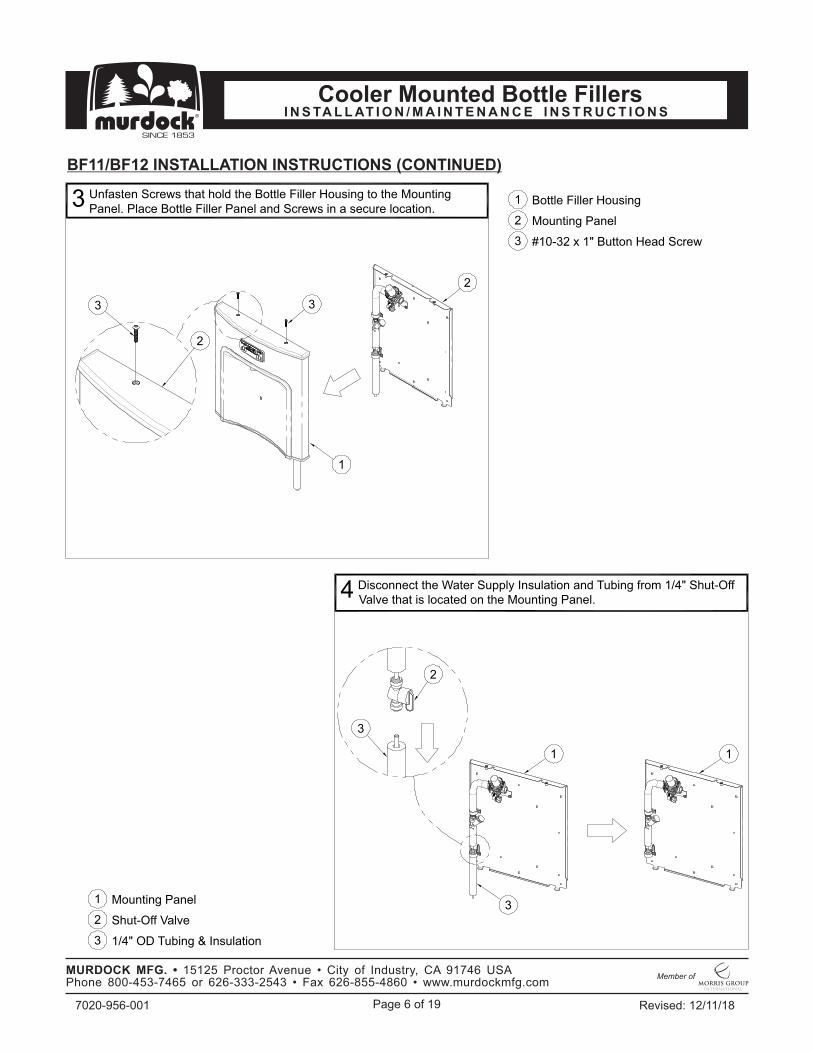
BF11/BF12 INSTALLATION INSTRUCTIONS (CONTINUED)
Bottle Filler Housing1
Mounting Panel2
#10-32 x 1" Button Head Screw3
Unfasten Screws that hold the Bottle Filler Housing to the MountingPanel. Place Bottle Filler Panel and Screws in a secure location.
3
Mounting Panel1
Shut-Off Valve2
1/4" OD Tubing & Insulation 3
Disconnect the Water Supply Insulation and Tubing from 1/4" Shut-OffValve that is located on the Mounting Panel.4
2
1
33
2
1
3
3
1
2
Page 7 of 19 Revised: 12/11/187020-956-001
MURDOCK MFG. • 15125 Proctor Avenue • City of Industry, CA 91746 USA Phone 800-453-7465 or 626-333-2543 • Fax 626-855-4860 • www.murdockmfg.com
Member of
I N S TA L L AT I O N / M A I N T E N A N C E I N S T R U C T I O N SCooler Mounted Bottle Fillers
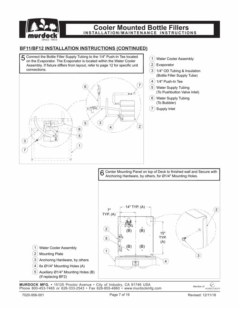
BF11/BF12 INSTALLATION INSTRUCTIONS (CONTINUED)
Water Cooler Assembly1
Evaporator2
Water Cooler Assembly1
Mounting Plate2
Anchoring Hardware, by others3
Connect the Bottle Filler Supply Tubing to the 1/4" Push-In Tee locatedon the Evaporator. The Evaporator is located within the Water CoolerAssembly. If fixture differs from layout, refer to page 12 for specific unitconnections.
5
Center Mounting Panel on top of Deck to finished wall and Secure withAnchoring Hardware, by others, for Ø1/4" Mounting Holes.
6
1/4" OD Tubing & Insulation3
1/4" Push-In Tee4
Water Supply Tubing5
Water Supply Tubing6
(To Pushbutton Valve Inlet)
(Bottle Filler Supply Tube)
14" TYP. (A)7"
TYP. (A)
15"TYP.(A)
(B)
(B)
(B)
(B)
6x Ø1/4" Mounting Holes (A)4
Auxiliary Ø1/4" Mounting Holes (B)5
(If replacing BF2)
7
24
35
1
2
3
4
1
5
2
7
3
5
6
Supply Inlet7
(To Bubbler)
6

Page 8 of 19 Revised: 12/11/187020-956-001
MURDOCK MFG. • 15125 Proctor Avenue • City of Industry, CA 91746 USA Phone 800-453-7465 or 626-333-2543 • Fax 626-855-4860 • www.murdockmfg.com
Member of
I N S TA L L AT I O N / M A I N T E N A N C E I N S T R U C T I O N SCooler Mounted Bottle Fillers
BF11/BF12 INSTALLATION INSTRUCTIONS (CONTINUED)
Water Cooler Deck1
1/4" OD Tubing & Insulation2
Water Cooler Deck1
Mounting Plate2
1/4" OD Tubing & Insulation3
Push Tubing with Insulation and Power Wires up through hole in Basin.Install Grommet.7
Connect Water Supply Tube to the 1/4" Shut-Off Valve that is locatedon the Mounting Panel. Refer to page 4 for proper connection.
8
Shut-Off Valve4
Grommet3
Power to Bottle Filler4
(Not required with BF11)
412" - 5"
1
2
4
3
1
2
4
3
412" - 5"

Page 9 of 19 Revised: 12/11/187020-956-001
MURDOCK MFG. • 15125 Proctor Avenue • City of Industry, CA 91746 USA Phone 800-453-7465 or 626-333-2543 • Fax 626-855-4860 • www.murdockmfg.com
Member of
I N S TA L L AT I O N / M A I N T E N A N C E I N S T R U C T I O N SCooler Mounted Bottle Fillers
BF11/BF12 INSTALLATION INSTRUCTIONS (CONTINUED)
! IMPORTANTFOR BF12 SERIES, FOLLOW STEP 9BFOR BF11 SERIES, FOLLOW STEP 9A
With Mounting Panel secured, place Bottle Filler Housing on top ofthe Water Cooler and connect water supply line from Bottle Filler toPneumatic Valve Outlet. Connect 1/8" Air-Line to Pushbutton andPneumatic Valve Inlet.
9A
With Mounting Panel secured, place Bottle Filler Housing on topof the Water Cooler and connect water supply line from BottleFiller to Solenoid Valve Outlet.
9B
BF11 SERIES
BF12 SERIES
Bottle Filler Housing1
Water Cooler Assembly2
1/4" O.D. Polyethylene Supply Line3
Pneumatic Valve4
3
6
Mounting Panel5
1/4"Min.
1
2
5
4
3
6
1/4"Min.
1
2
5
4
Valve Water Supply Outlet Elbow6
Valve Air-Line Supply Inlet7
1/8" O.D. Polyethylene Supply Line8
Pushbutton9
1/4"Min.
Bottle Filler Housing1
Water Cooler Assembly2
1/4" O.D. Polyethylene Supply Line3
Solenoid Valve4
Mounting Panel5
Valve Water Supply Outlet Elbow6
7
8
8
9
Page 10 of 19 Revised: 12/11/187020-956-001
MURDOCK MFG. • 15125 Proctor Avenue • City of Industry, CA 91746 USA Phone 800-453-7465 or 626-333-2543 • Fax 626-855-4860 • www.murdockmfg.com
Member of
I N S TA L L AT I O N / M A I N T E N A N C E I N S T R U C T I O N SCooler Mounted Bottle Fillers
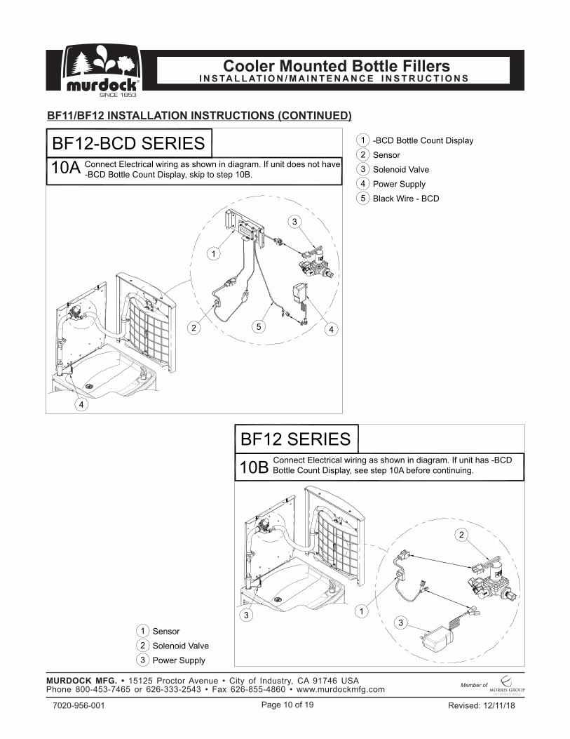
BF11/BF12 INSTALLATION INSTRUCTIONS (CONTINUED)
-BCD Bottle Count Display1
Sensor2
Solenoid Valve3
Power Supply4
Black Wire - BCD5
Connect Electrical wiring as shown in diagram. If unit does not have-BCD Bottle Count Display, skip to step 10B.10A
Connect Electrical wiring as shown in diagram. If unit has -BCDBottle Count Display, see step 10A before continuing.10B
Sensor1
Solenoid Valve2
Power Supply3
BF12-BCD SERIES
BF12 SERIES
1
3
4
3
2
1
5
4
3
2

Page 11 of 19 Revised: 12/11/187020-956-001
MURDOCK MFG. • 15125 Proctor Avenue • City of Industry, CA 91746 USA Phone 800-453-7465 or 626-333-2543 • Fax 626-855-4860 • www.murdockmfg.com
Member of
I N S TA L L AT I O N / M A I N T E N A N C E I N S T R U C T I O N SCooler Mounted Bottle Fillers
BF11/BF12 INSTALLATION INSTRUCTIONS (CONTINUED)
Connect Power Supply, turn on water and check for leaksthroughout the system.11
Mount Water Cooler Access Panel to Water Cooler.
12
13
With fixture tested, install Housing to Mounting Panel. AngleHousing and engage Housing Bottom Flange to Mounting PanelFlange and close unit. Secure with Screws from step 3.
2
5
3
12
4
2
1
2
1
4
2
13
5
3
Mounting Panel1
Water Cooler Assembly2
Bottle Filler Housing3
Power Supply4
Solenoid Valve5
Bottle Filler Housing1
Mounting Panel2
#10-32 x 1" Button Head Screw3
Housing Bottom Flange4
Mounting Panel Flange5
Water Cooler1
Bottle Filler2
Access Panel3
Page 12 of 19 Revised: 12/11/187020-956-001
MURDOCK MFG. • 15125 Proctor Avenue • City of Industry, CA 91746 USA Phone 800-453-7465 or 626-333-2543 • Fax 626-855-4860 • www.murdockmfg.com
Member of
I N S TA L L AT I O N / M A I N T E N A N C E I N S T R U C T I O N SCooler Mounted Bottle Fillers
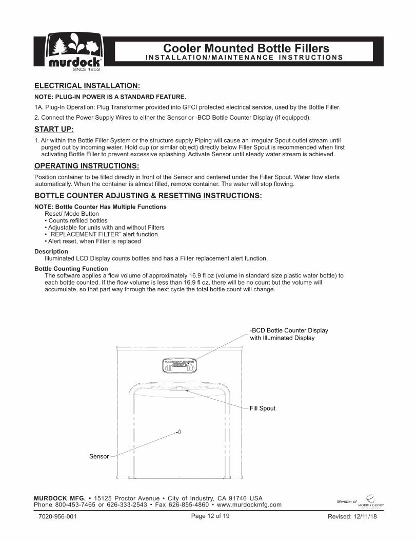
2. Connect the Power Supply Wires to either the Sensor or -BCD Bottle Counter Display (if equipped).
DescriptionIlluminated LCD Display counts bottles and has a Filter replacement alert function.
Bottle Counting FunctionThe software applies a flow volume of approximately 16.9 fl oz (volume in standard size plastic water bottle) to each bottle counted. If the flow volume is less than 16.9 fl oz, there will be no count but the volume will accumulate, so that part way through the next cycle the total bottle count will change.
NOTE: PLUG-IN POWER IS A STANDARD FEATURE.
OPERATING INSTRUCTIONS:
BOTTLE COUNTER ADJUSTING & RESETTING INSTRUCTIONS:
ELECTRICAL INSTALLATION:
1. Air within the Bottle Filler System or the structure supply Piping will cause an irregular Spout outlet stream until purged out by incoming water. Hold cup (or similar object) directly below Filler Spout is recommended when first activating Bottle Filler to prevent excessive splashing. Activate Sensor until steady water stream is achieved.
1A. Plug-In Operation: Plug Transformer provided into GFCI protected electrical service, used by the Bottle Filler.
START UP:
NOTE: Bottle Counter Has Multiple FunctionsReset/ Mode Button• Counts refilled bottles• Adjustable for units with and without Filters• “REPLACEMENT FILTER” alert function• Alert reset, when Filter is replaced
Position container to be filled directly in front of the Sensor and centered under the Filler Spout. Water flow starts automatically. When the container is almost filled, remove container. The water will stop flowing.
Fill Spout
Sensor
-BCD Bottle Counter Displaywith Illuminated Display

Page 13 of 19 Revised: 12/11/187020-956-001
MURDOCK MFG. • 15125 Proctor Avenue • City of Industry, CA 91746 USA Phone 800-453-7465 or 626-333-2543 • Fax 626-855-4860 • www.murdockmfg.com
Member of
I N S TA L L AT I O N / M A I N T E N A N C E I N S T R U C T I O N SCooler Mounted Bottle Fillers
BF11/BF12 Water Supply Tubing Diagram
Install Tubing as shown below to add Bottle Filler to Fixture
Water Supply Line, to Bubbler1
Water Supply Line, to Bottle Filler2
1/4" O.D. Push-In Tee3
Water Supply Line, Inlet4
Foam Insulation5
3
2 5
Non-Refrigerated Unit(Drinking Fountain)
Non-Pressurized Unit(Water Cooler)
Pressurized Unit(Water Cooler)
Pressurized with Bottle Filler
Page 14 of 19 Revised: 12/11/187020-956-001
MURDOCK MFG. • 15125 Proctor Avenue • City of Industry, CA 91746 USA Phone 800-453-7465 or 626-333-2543 • Fax 626-855-4860 • www.murdockmfg.com
Member of
I N S TA L L AT I O N / M A I N T E N A N C E I N S T R U C T I O N SCooler Mounted Bottle Fillers
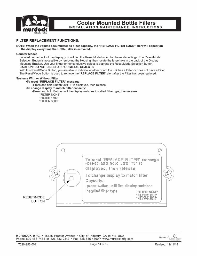
“FILTER 1500”
FILTER REPLACEMENT FUNCTIONS:
NOTE: When the volume accumulates to Filter capacity, the “REPLACE FILTER SOON” alert will appear on the display every time the Bottle Filler is activated.
-Press and hold Button until the display matches installed Filter type, then release.
Systems With or Without Filter:•To reset “REPLACE FILTER” message: -Press and hold Button until “3” is displayed, then release.•To change display to match Filter capacity:
“FILTER NONE”
“FILTER 3000”
Counter ModesLocated on the back of the display you will find the Reset/Mode button for the mode settings. The Reset/Mode Selection Button is accessible by removing the Housing, then locate the large hole in the back of the Display Mounting Bracket. Use your finger or nonconductive object to depress the Reset/Mode Selection Button.CAUTION: DO NOT USE SHARP OR METAL OBJECTSWith this Reset/Mode Button, you are able to indicate whether or not the unit has a Filter or does not have a Filter. The Reset/Mode Button is used to remove the “REPLACE FILTER” alert after the Filter has been replaced.
RESET/MODEBUTTON

Page 15 of 19 Revised: 12/11/187020-956-001
MURDOCK MFG. • 15125 Proctor Avenue • City of Industry, CA 91746 USA Phone 800-453-7465 or 626-333-2543 • Fax 626-855-4860 • www.murdockmfg.com
Member of
I N S TA L L AT I O N / M A I N T E N A N C E I N S T R U C T I O N SCooler Mounted Bottle Fillers
3. RESTRICTED OR NO WATER FLOW a. Ensure Water Supply service stop valve is fully open. b. Verify minimum 20 PSIG supply line flow pressure. c. Check for twist or kinks in Spout Tubing. d. Check the water inlet “Y’’ Strainer. Sediment from the main supply can get trapped in the Screen along with installation materials such as pipe dope and flux. The Screen should be cleaned and checked on a regular basis and replace if needed. e. Flow Control in spout clogged, remove & clean. f. The Water Cooler may also develop a freezing condition in which the water will become frozen inside the Evaporator coil. This indicates a refrigeration problem or Thermostat failure in which case the Water Cooler needs to be checked by a qualified technician. g. No power to Transformer connections loose or wires cut.
1. IF LIGHT WITHIN SENSOR DOES NOT FLASH ONCE WHEN USER IS WITHIN RANGE: a. Verify 120VAC input & 9VDC output of Transformer. b. Replace defective Transformer. c. Sensor in “Security Mode” after 20 seconds of constant detection. Remove source of detection and wait 30 seconds before checking. d. Sensor is picking up a highly reflective surface. Eliminate cause of reflection and wait 30 seconds before checking. e. Replace defective sensor.
TROUBLE-SHOOTING:
2. IF LIGHT WITHIN SENSOR LENS FLASHES ONCE WHEN THE USER IS WITHIN RANGE: a. Repair bad connection from Sensor to Solenoid. b. There is debris or scale in the Solenoid assembly. Remove Solenoid, pull out Plunger and Spring. Clean with scale remover solution. c. There is debris or scale in center or two holes in convolution of the water diaphragm. Remove and clean.
CLEANING & MAINTENANCE GUIDE: 1. To remove water spots or rust spots, stainless steel cleaner/polish on a cloth is recommended. 2. If there are stubborn spots or if you wish to treat a scratch, synthetic abrasive general purpose pads
® such as Scotch-Brite is recommended. 3. Apply stainless steel cleaner/polish to the synthetic abrasive pads and carefully rub the panel with the grain. 4. Do NOT use harsh chemicals, abrasive or petroleum based cleaners. Use of these will void the Murdock warranty. DO NOT use abrasives on powder coated units. 5. Stainless steel should be kept clean at all times. If a coating of stainless steel cleaner/ polish is maintained, stainless steel surfaces will retain their new, clean, polished appearance indefinitely. Use clean mild soapy water for powder coated units. 6. Periodically remove Panels and clean out inline “Y’’ Strainer.

Page 16 of 19 Revised: 12/11/187020-956-001
MURDOCK MFG. • 15125 Proctor Avenue • City of Industry, CA 91746 USA Phone 800-453-7465 or 626-333-2543 • Fax 626-855-4860 • www.murdockmfg.com
Member of
I N S TA L L AT I O N / M A I N T E N A N C E I N S T R U C T I O N SCooler Mounted Bottle Fillers
ITEM # PART NUMBER DESCRIPTION ITEM # PART NUMBER DESCRIPTION
1 CONTACT FACTORY HOUSING ASSEMBLY, BF11 12 2150-003-199 1/8" OD LDPE TUBE, NATURAL, 3' LONG
2 7014-257-000 BOTTOM TRIM, H202GO 13 7100-441-000 LOCKING GROMMET,1.188 DIA HOLE
3 0116-123-000 #10-32 x 1" BUTTON HEAD SCREW 14 2566-160-001 (-PBH) SIDE OUTLET PUSHBUTTON
4 1895-710-000 1/4" PUSH-IN UNION TEE 15 4005-030-199 AIR-TROL PUSHBTN ESCUTCHEON S/S
5 2169-000-000 1/4" O.D. LLDPE TUBING, BLUE 16 4005-031-199 AIR-TROL PUSHBUTTON
6 7012-055-000 FOAM PIPE INSULATION 17 2566-025-002 SIDE OUTLET PUSHBUTTON SUB-ASSY
7 7000-420-000 1/4 TURN SHUT-OFF VALVE 18 2566-022-000 ESCUTCHEON RETAINER
8 7013-210-001 "Y" STRAINER, BOTTLE FILLER 19 2566-001-000 AIR DIAPHRAGM
9 7014-290-005 PNEUMATIC VALVE MOUNTING ASSY 20 2566-055-199 DIAPHRAGM RETAINER SIDE OUTLET
10 0302-011-000 #6-32 UNC HEX NUT 21 1895-450-000 1/8" O.D. NYLON COMPRESSION NUT
11 1895-709-000 ELBOW, 1/4" PUSH-IN x 1/4" STEM 22 7013-119-000 NEOPERL LAMINAR NOZZLE
BF11 PARTS LIST BOTTLE FILLER PARTS BREAKDOWN
8
7
4
1
2
3
11
65
65
65
9
12
10
14
13
15
16
18
19
20
2117
22

Page 17 of 19 Revised: 12/11/187020-956-001
MURDOCK MFG. • 15125 Proctor Avenue • City of Industry, CA 91746 USA Phone 800-453-7465 or 626-333-2543 • Fax 626-855-4860 • www.murdockmfg.com
Member of
I N S TA L L AT I O N / M A I N T E N A N C E I N S T R U C T I O N SCooler Mounted Bottle Fillers
ITEM # PART NUMBER DESCRIPTION ITEM # PART NUMBER DESCRIPTION
1 CONTACT FACTORY HOUSING ASSEMBLY, BF11/12 11 7012-055-000 FOAM PIPE INSULATION
2 7014-257-000 BOTTOM TRIM, H202GO 12 7000-420-000 1/4 TURN SHUT-OFF VALVE
3 2563-381-001 SENSOR "A" ASSEMBLY 13 7013-210-001 "Y" STRAINER, BOTTLE FILLER
4 0110-012-000 #6 x 3/16" TRUSS HEAD SCREW 14 7014-293-001 SOLENOID/VALVE MOUNTING ASSY
5 0716-111-001 BOTTLE COUNTER WITH CONNECTORS 15 0302-011-000 #6-32 UNC HEX NUT
6 0110-011-000 #6 x 3/16" PAN HEAD SCREW 16 0710-731-001 POWER SUPPLY
7 7014-253-199 SPLASH GUARD 17 1895-709-000 ELBOW, 1/4" PUSH-IN x 1/4" STEM
8 0116-123-000 #10-32 x 1" BUTTON HEAD SCREW 18 7100-441-000 LOCKING GROMMET,1.188 DIA HOLE
9 1895-710-000 1/4" PUSH-IN UNION TEE 19 7013-119-000 NEOPERL LAMINAR NOZZLE
10 2169-000-000 1/4" O.D. LLDPE TUBING, BLUE
BF12 PARTS LIST BOTTLE FILLER PARTS BREAKDOWN
14
13
12
9
1
2
4
3
5
6
7
6
8
15
16
1110
1110
1110
18
17
19
Page 18 of 19 Revised: 12/11/187020-956-001
MURDOCK MFG. • 15125 Proctor Avenue • City of Industry, CA 91746 USA Phone 800-453-7465 or 626-333-2543 • Fax 626-855-4860 • www.murdockmfg.com
Member of
I N S TA L L AT I O N / M A I N T E N A N C E I N S T R U C T I O N SCooler Mounted Bottle Fillers
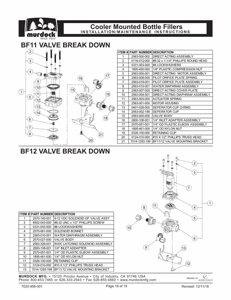
BF11 VALVE BREAK DOWN
BF12 VALVE BREAK DOWN
ITEM # PART NUMBER DESCRIPTION
1 2563-000-002 DIRECT ACTING ASSEMBLY
2 0116-012-000 #8-32 x 1-1/4" PHILLIPS ROUND HEAD
3 0331-003-000 #8 LOCKWASHERS
4 1895-450-000 1/8" PLASTIC COMPRESSION NUT
5 2563-000-001 DIRECT ACTING MOTOR ASSEMBLY
6 2563-008-000 PILOT ORIFICE PLATE SPRING
7 2563-019-001 PILOT ORIFICE PLATE ASSEMBLY
8 2563-010-001 WATER DIAPHRAM ASSEMBLY
9 2563-007-000 DIRECT ACTING COVER PLATE
10 2563-004-001 DIRECT ACTING DIAPHRAM ASSEMBLY
11 2563-003-000 ACTUATOR SPRING
12 2563-001-000 MOTOR HOUSING
13 0401-026-000 SEPERATOR CUP O-RING
14 2563-002-199 SEPERATOR CUP
15 2563-000-000 VALVE BODY
16 2800-108-001 1/4" INLET ADAPTER ASSEMBLY
17 2570-051-001 1/4" OD PLASTIC ELBOW ASSEMBLY
18 1895-461-000 1/4" OD NYLON NUT
19 0326-100-000 RETAINING CLIP
20 0124-010-000 #10 X 1/2" PHILLIPS TRUSS HEAD
21 7014-1293-199 BF11/12 VALVE MOUNTING BRACKET
ITEM # PART NUMBER DESCRIPTION
1 2570-140-001 9-12 VDC SOLENOID OP VALVE ASSY
2 6502-043-000 #8-32 UNC x 1/2" PHILLIPS SCREW
3 0331-003-000 #8 LOCKWASHERS
4 2570-061-000 SOLENOID BONNET
5 2563-010-001 WATER DIAPHRAGM ASSEMBLY
6 2570-027-000 VALVE BODY
7 2563-326-001 9VDC LATCHING SOLENOID ASSEMBLY
8 2800-108-001 1/4" INLET ADDAPTER
9 2570-051-001 1/4" OD PLASTIC ELBOW ASSEMBLY
10 1895-461-000 1/4" OD NYLON NUT
11 0326-100-000 RETAINING CLIP
12 0124-010-000 #10 X 1/2" PHILLIPS TRUSS HEAD
13 7014-1293-199 BF11/12 VALVE MOUNTING BRACKET
1
2
4
3
5
6
7
8
9
11
12
13
14
10
17
20
21
18
16
15
19
1
2
3
4
5
6
7
118
10
9 13
12

Page 19 of 19 Revised: 12/11/187020-956-001
MURDOCK MFG. • 15125 Proctor Avenue • City of Industry, CA 91746 USA Phone 800-453-7465 or 626-333-2543 • Fax 626-855-4860 • www.murdockmfg.com
Member of
I N S TA L L AT I O N / M A I N T E N A N C E I N S T R U C T I O N SCooler Mounted Bottle Fillers
MA IL A D D R ESS P.O . BOX 3 5 2 7
C ITY OF IN D U STRY, C A 9 1 7 4 4 U .S .A .
PH YSIC A L A D D R ESS 1 5 1 2 5 PR OC TOR AVEN U E
C ITY OF IN D U STRY, C A 9 1 7 4 6 U .S .A .
TOLL FR EE 8 0 0 -5 9 1 -9 3 6 0 • LOC A L 6 2 6 -3 3 6 -4 5 6 1FA X 6 2 6 -8 5 5 -4 8 9 4 • WEB w w w.mu rd o ckmfg . co m
Murdock warrants that its products are free from defects in material or workmanship under normal use and service for a period of one year from date of install or for 18 months after the date of shipment from the factory, whichever comes first. The sealed refrigeration system is warranted for five years. Murdock’s liability under this warranty shall be discharged solely by replacement or repair of defective material, provided Murdock is notified in writing within one year from date of shipment, F.O.B. Industry, California.
NOTES TO INSTALLER:1. Please leave this documentation with the owner of the fixture when finished. 2. Please read this entire booklet before beginning the installation. 3. Check your installation for compliance with plumbing, electrical and other applicable codes.
LIMITED WARRANTY - UNITED STATES & CANADA
This warranty does not cover installation or labor charges and does not apply to materials, which have been damaged by other causes such as mishandling or improper care or abnormal use. The repair or replacement of the defective materials shall constitute the sole remedy of the Buyer and the sole remedy of Murdock under this warranty. Murdock shall not be liable under any circumstances for incidental, consequential or direct charges caused by defects in the materials, or any delay in the repair or replacement thereof. This warranty is in lieu of all other warranties expressed or implied. Product maintenance instructions are issued with each unit and disregard or non-compliance with these instructions will constitute an abnormal use condition and void the warranty. Stainless steel must be protected on job site during construction and must be properly maintained after the water has been introduced into the water cooler or drinking fountain, or Mudock’s limited warranty is void.
LIMITED EXPORT WARRANTY - One year on parts only.