“What NALA knows about who is using ” Margaret Murray, NALA Family Literacy Conference November 2013

www.coolblue-mhw.com 201-252-8125 CoolBLUE®@MHW-Intl.com
CoolBLUE® Inductive AbsorbersNaLA® Noise Line Absorbers
Motor Bearing and Stray Ground Current
Solution from MH&W International Corp.

[email protected]://www.coolblue-mhw.com MH&W International Corp. • 575 Corporate Drive, Mahwah, NJ 07430 • (201) 252-8125
Variable Frequency Motor Drive Systems
1. What is the problem
2. Determining the problem
3. Testing the system
4. What solves the problem (Temporary fix, or solid solution)
5. Tools
6. Real industry solutions
9/14/2017

[email protected]://www.coolblue-mhw.com MH&W International Corp. • 575 Corporate Drive, Mahwah, NJ 07430 • (201) 252-8125
Variable Frequency Motor Drive Systems
The Variable Frequency Drive (VFD) was created approximately 30+ years ago to providesubstantial energy savings and precise control in commercial and industrial applications.Necessary changes from traditional markets of fossil fuel have led to markets for alternativepower generation as well. All of these markets have benefitted from VFD’s.
Advantages of VFD’s1. Fast switching
2. Speed variation
3. Heavy load inertia starting
4. High starting torque requirements
5. Low starting current requirements
6. High efficiency at low speed
7. High power factor
8. Lower power
9/14/2017

[email protected]://www.coolblue-mhw.com MH&W International Corp. • 575 Corporate Drive, Mahwah, NJ 07430 • (201) 252-8125
Problems with IGBT SystemsVFD systems are not sinusoidal but are a continuous generation of pulses (PulseWidth Modulation or PWM). The pulses have a constant voltage and a dv/dt rise andfall time of the pulse. The original VFD systems were based on Bipolar JunctionTransistors. The trend now is toward IGBT (Insulated Gate Bipolar Transistor fromMitsubishi, On Semi, Infineon, ST Micro, etc.) systems which give a faster switchingdv/dt with lower switching losses and a more efficient drive.
IGBT systems create problems associated with the system performance. The IGBT introduces parasitic currents in the form of two potential destructive characteristics:
a. Transient Voltage/ Harmonic Distortion/Reflective Waves
b. Higher magnitudes of electrical ground noise current
9/14/2017

[email protected]://www.coolblue-mhw.com MH&W International Corp. • 575 Corporate Drive, Mahwah, NJ 07430 • (201) 252-8125
Electrical Discharge Machining
AC Motor Drive systems utilizing variable frequencycontrols produce high frequency electrical noise. Thenoise is superimposed on the power drive lines of themotors in the form of common mode noise. Thecommon mode noise creates a voltage (dv/dt) acrossthe rotor/stator of the motor resulting in a dischargecurrent through the lubrication and motor bearings tothe motor raceway.
This current discharge produces an EDM effect(Electrical Discharge Machining) that causesdestructive pitting and damage to the motor raceway,and premature lubrication breakdown. The end resultis premature failure of the motor causing expensiverepairs and system downtime.
Example: Outer Bearing Race Fluting EDMResults from VFD Induced Common Mode Noise
9/14/2017

[email protected]://www.coolblue-mhw.com MH&W International Corp. • 575 Corporate Drive, Mahwah, NJ 07430 • (201) 252-8125
Problems with IGBT Systems
Each pulse in a PWM system is not a clean squarepulse. Each Rise and Fall of the pulse has an overshoot or transient over‐voltage. This over‐voltagephenomenon is also known as "Reflected Wave","Transmission Line Effect" or "Standing Wave".
The per unit overvoltage magnitude is dependentupon drive‐cable‐motor circuit dynamics definedby drive output voltage magnitude and rise time,cable surge impedance characteristics, motorsurge impedance to the pulse voltage, cablelength and spacing of the train of pulses by thePWM modulator.
9/14/2017

[email protected]://www.coolblue-mhw.com MH&W International Corp. • 575 Corporate Drive, Mahwah, NJ 07430 • (201) 252-8125
Example of High Frequency Noise
Here is a typical example of the high frequencynoise generated by the IGBT devices in a motorsystem.
The yellow line at top of screen indicates theswitching of the IGBT in the drive. The greenline indicates the high frequency noisegenerated creating the destructive commonmode currents.
9/14/2017

[email protected]://www.coolblue-mhw.com MH&W International Corp. • 575 Corporate Drive, Mahwah, NJ 07430 • (201) 252-8125
Example of High Frequency Noise
As the frequency of the common mode noiseincreases, the impedance of the system goesdown. This graph shows how low the impedancegoes as the frequency increases from Hz to MHz.The decrease in the impedance (systemresistance) allows more and more current toflow.
9/14/2017

[email protected]://www.coolblue-mhw.com MH&W International Corp. • 575 Corporate Drive, Mahwah, NJ 07430 • (201) 252-8125
High Frequency Noise VersusTypical Line Frequencies (50-60Hz)
A common misconception of high frequency in modern day VFD motor applications is to viewand associate with 50/60Hz up to 50kHz.
Because of the high speed switching of IGBT’s, the noise (high frequency current) is in themegahertz (MHz) range. Typical systems will see these high frequencies from severalhundred kilohertz, up to 5MHz.
Understanding of these high frequencies is beyond most electrical system operatorsexperience. A better understanding will follow in this presentation.
Measuring, and viewing, these high frequencies cannot be seen and accurately measured witha standard amp meter for two reasons. 1) a typical clamp meter will only measure RMS (oraverage), therefore the measurement will not display peak currents. 2) a typical meter willnot accurately display the true frequencies. Most meters will only see up to 50kHz. Again,true measurements are in the hundreds of kilohertz up to 5MHz.
9/14/2017

[email protected]://www.coolblue-mhw.com MH&W International Corp. • 575 Corporate Drive, Mahwah, NJ 07430 • (201) 252-8125
Determining the Problem
1) Electrical Discharge Detection
2) Shaft Voltage Measurement
3) Measuring High Frequency Current
9/14/2017

[email protected]://www.coolblue-mhw.com MH&W International Corp. • 575 Corporate Drive, Mahwah, NJ 07430 • (201) 252-8125
Determining the ProblemElectrical Discharge Detection
The electrical discharge in a motor bearing is a charge-discharge similar to a spark. A largecurrent is flowing from a high potential to ground. This spark, or arc, generates a highfrequency noise that can be detected. A test instrument with antennae attempts to senseevery time the spark is generated and discharged.
Holding the instrument close to the motor shaft where the motor bearings are located, theequipment attempts to measures every high frequency current discharge thru the bearings.
This is a relatively safe method of identifying potential problems in that there is no contactwith the motor.
Although this is a relatively safe method of testing for discharges, it does not accuratelymeasure the actual discharges. Other outside influences can impact the devicesmeasurements.
9/14/2017

[email protected]://www.coolblue-mhw.com MH&W International Corp. • 575 Corporate Drive, Mahwah, NJ 07430 • (201) 252-8125
Determining the ProblemMeasuring Shaft Voltage
Shaft Grounding
There are methods of testing the voltage discharge from shaft to ground by use of brush or wire attached to an oscilloscope probe and touching rotating shaft.
1. Method of testing with brush probe is dangerous, and sometimes not accessible, especially in vertical mount or medium voltagemotors. A large number of corporations forbid this type of field testing due to safety concerns. Due to these concerns and risks, testing is not advised!
2. The shaft must be properly cleaned and prepped in order to make sufficient contact. This is done by smoothing or lightly sanding the surface area of the shaft.
3. Key way must be filled with some type of filler in order to make constant contact with the shaft.
4. The probe must be placed on it’s stand in a way that the brush makes continual contact with rotating shaft.
5. Must obtain access to shaft, prepare shaft, install probe on motor shaft, powering system up, powering system down, and disconnecting probe.
6. Medium Voltage applications, and explosion potential applications are not accessible for this method.
Warning! This method of testing is not advised due to the risks
associated with rotating shaft, and proximity of the load!
9/14/2017

[email protected]://www.coolblue-mhw.com MH&W International Corp. • 575 Corporate Drive, Mahwah, NJ 07430 • (201) 252-8125
Determining the ProblemMeasuring High Frequency Current
How To Properly Measure Common Mode Currents (CMC)
The simplest and safest way to measure CMC is with a flexible, clip-around,
Rogowski coil. This method is used to measure high frequency destructive
common mode currents in motor drives . . . high frequencies produced by
motor drive IGBT’s in the kHz up to several MHz’s.
The high frequency Rogowski coil simply connects around the 3 power
phases of cable going from the drive to the motor to measure common mode
current. If multiple cables per phase, coil would still go around all cables.
The output of the Rogowski coil connects to any oscilloscope (suggested
100MHz and above), and measures the common mode current.
Simply power down, place the Rogowski coil around 3 phases of power.
Power up system. Measure current.
9/14/2017

[email protected]://www.coolblue-mhw.com MH&W International Corp. • 575 Corporate Drive, Mahwah, NJ 07430 • (201) 252-8125
Solutions
There are three methods commonly employed to remove the effects of damaging currents on VFD motor systems:
1. Shaft Grounding Device (commonly know as a current diverter)
2. Insulated Bearings
3. Inductive Absorption Device
9/14/2017

[email protected]://www.coolblue-mhw.com MH&W International Corp. • 575 Corporate Drive, Mahwah, NJ 07430 • (201) 252-8125
Shaft Grounding Devices (Current Diverter)Warning: This device is not recommended for use!
A mechanical brush device that “rides” on the motor shaft. The device attempts to divert current directly to ground (via motor casing) through the brush. Problems associated with this device:
1. Brushes must be properly maintained/replaced–system becomes expensive over time.
2. Brushes lose contact with the shaft over time due to high current flow, heat, contaminants, and physical wear.
3. This method does not absorb the voltage or current. Shaft grounding just diverts the voltage to ground, and does not absorb the current. If system ground is insufficient, the path could be through other parts of the systems.
4. Must be maintained and/or replaced periodically causing downtime for maintenance.
5. This solution is only targeted at protecting motor bearings. A significant problem in the field is with stray capacitive currents flowing through other motor system devices such as sensors, detectors, and other system communications. Shaft grounding just adds to this problem by allowing current to flow into the overall system associated with poor system grounding.
6. 75HP and above must have isolated/hybrid bearing on opposite end to force current through brush. Added cost and maintenance time.
7. Literally hundreds of choices of solutions. i.e. epoxy, drill and tap, shaft size varies per hp/ kilowatts, wash down applications, chemical/harsh environment resistant, hazardous conditions safety, poor grounding of motor casing.
8. While voltage is part of the formula of power, watts are the destructive force (V * I = Watts). For example, 30 volts times 1 amp is 30 Watts of power. 30 volts times .1 amp is only 3 watts. Absorbing the current at the source near the IGBT’s , before it gets to the motor is the solution…not diverting it somewhere else after current flows through the motor!
9/14/2017

[email protected]://www.coolblue-mhw.com MH&W International Corp. • 575 Corporate Drive, Mahwah, NJ 07430 • (201) 252-8125
Insulated Bearings
This is a mechanical solution where the motor bearings are made of aninsulated material or insulated coating. There are problems associatedwith this solution, and they are:
1. Expensive. Installation, bearing costs, replacements, and does not absorb or remove the actual current flowing.
2.Motor bearings do have to be replaced, increasing the expense over time.
3. This solution only attempts to protect the motor bearings.
4. Increased heat in system because motor cannot provide a path for the current.
9/14/2017

[email protected]://www.coolblue-mhw.com MH&W International Corp. • 575 Corporate Drive, Mahwah, NJ 07430 • (201) 252-8125
Inductive Absorption CoolBLUE®
The only SOLUTION for permanently removing
damaging currents is to install a common mode choke
around the power conductors going from VFD to
motor. CoolBLUE® devices actually absorb the
damaging currents at the source of the noise (the VFD
IGBT’s)…well before the damaging currents reach the
motor.
CoolBLUE® Inductive Absorbers actually absorb the energy. This is a permanent solution, not a Band-Aid!
9/14/2017

[email protected]://www.coolblue-mhw.com MH&W International Corp. • 575 Corporate Drive, Mahwah, NJ 07430 • (201) 252-8125
Inductive Absorption CoolBLUE®
What is a common mode choke? In electronics, a choke is an inductor used to block high frequency alternating current (AC) in an electrical circuit, while passing lower-frequency or direct current (DC). The choke's impedance increases with frequency.
The name comes from blocking—“choking”—high frequencies while passing low frequencies. It is a functional name; the name “choke” is used if an inductor is used for blocking or decoupling higher frequencies.
CoolBLUE® Inductive Absorbers actually absorb the energy.
9/14/2017

[email protected]://www.coolblue-mhw.com MH&W International Corp. • 575 Corporate Drive, Mahwah, NJ 07430 • (201) 252-8125
CoolBLUE® Inductive AbsorberCommon Mode Choke
A common mistake with CoolBLUE® is to look for a reduction in shaft voltage. Clearly, a choke, in this case CoolBLUE®, reduces current, not voltage (per definition of a choke mentioned previously).
A certain manufacturer of a shaft voltage diverter rings attempts to disqualify CoolBLUE® with this misinformation. Again, a choke, in this case CoolBLUE®, absorbs high frequency CURRENT, not voltage. Clearly, they attempt to mislead the market with a Band-Aid instead of a clearly superior solution for customers.
9/14/2017

[email protected]://www.coolblue-mhw.com MH&W International Corp. • 575 Corporate Drive, Mahwah, NJ 07430 • (201) 252-8125
CoolBLUE® Inductive Absorber
Note of importance:CoolBLUE® Inductive Absorbers have two important functions in a VFD motor system.
1) Reduce the damaging common mode currents.
2) Reduce the high frequency (dv/dt), thereby reducing current further by increasing the system impedance.
9/14/2017

[email protected]://www.coolblue-mhw.com MH&W International Corp. • 575 Corporate Drive, Mahwah, NJ 07430 • (201) 252-8125
CoolBLUE® Inductive AbsorberMeasuring Common Mode Current and Shaft Voltage
Measuring just voltage won’t show how much current. Measuring just current won’t show how much voltage. However, putting them both on the screen at the same time shows the voltage and current effects of CoolBLUE®.
Yellow signal on channel one indicates shaft voltage measured with a voltage brush “riding” on the motor shaft. Blue
signal on channel two shows current measured with a Rogowski coil around three phases of power cables.Figure one shows before the addition of CoolBLUE®. Figure two shows after CoolBLUE® installed.
Voltage VoltageCurrent Current
Before CoolBLUE® After CoolBLUE®
9/14/2017
[email protected]://www.coolblue-mhw.com MH&W International Corp. • 575 Corporate Drive, Mahwah, NJ 07430 • (201) 252-8125
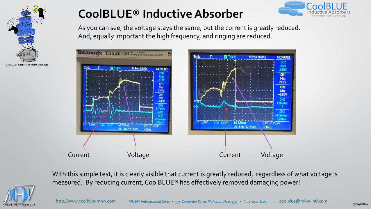
As you can see, the voltage stays the same, but the current is greatly reduced.And, equally important the high frequency, and ringing are reduced.
With this simple test, it is clearly visible that current is greatly reduced, regardless of what voltage is measured. By reducing current, CoolBLUE® has effectively removed damaging power!
Current CurrentVoltage Voltage
CoolBLUE® Inductive Absorber
9/14/2017

[email protected]://www.coolblue-mhw.com MH&W International Corp. • 575 Corporate Drive, Mahwah, NJ 07430 • (201) 252-8125
Inductive AbsorptionCommon Mode Choke
Inductive absorption is an electrical solution where inductivecomponents are placed over the drive cables to absorb thetransient voltage and common mode currents. The inductivecomponents need to have high permeability, high saturation,and low power loss. They do not affect the symmetricalpower currents but efficiently dampen the asymmetrical EMInoise currents. This creates a common mode choke.
The initial installation cost is about the same, or less, as othersolutions. The long term costs are negligible as there is nomaintenance, or replacement ever needed with this solution.
9/14/2017

[email protected]://www.coolblue-mhw.com MH&W International Corp. • 575 Corporate Drive, Mahwah, NJ 07430 • (201) 252-8125
The Inductive Absorber -Common Mode Choke Solution
The advantages of the Inductive Absorber/Common Mode Choke solution are:
• Installations is less than shaft grounding or insulated bearings.
• Easy to install around power cables.
• Reduces line noise by a factor of 4:1 or better.
• Can be retrofitted to any system with little effort in the field.
• Reduces transient voltages, stray capacitive currents, and common mode currents before they reach the motor system.
• Small number of cores fit all motor applications (AC, DC, Servo, Medium voltage, etc.)
• Other electronic devices in the systems like sensors, monitors, metal detectors are protected as well as motor bearings.
• Lifelong solution – magnetic properties do not degrade over time nor affected by heat. This is a solution, not temporary fix like other devices.
9/14/2017

[email protected]://www.coolblue-mhw.com MH&W International Corp. • 575 Corporate Drive, Mahwah, NJ 07430 • (201) 252-81259/14/2017

[email protected]://www.coolblue-mhw.com MH&W International Corp. • 575 Corporate Drive, Mahwah, NJ 07430 • (201) 252-8125
Correct Installation of CoolBLUE® and Nala® Cores
CoolBLUE® - All power cables must go through CoolBLUE® cores as shown below. No grounding wire or shielding. In the case of multiple conductors, all power conductors go through cores (as shown below). No ground or shielding.
Nala® - Each power cable must have at least one Nala® core per cable. In multipower-cable applications, a Nala® must be on each cable.
Multi-conductor Example
9/14/2017

[email protected]://www.coolblue-mhw.com MH&W International Corp. • 575 Corporate Drive, Mahwah, NJ 07430 • (201) 252-8125
Correct Installation of CoolBLUE® CoresShield and ground MUST be removed before inserting through cores. Shield and ground bypass the cores providing an alternative path around cores in effect disabling the core functionality.
Use of shielded cable, without removing ground and shield, will disable CoolBLUE®. Shield and ground must be peeled back far enough to allow cores around cables without disruption. Once shielding is not through cores, reconnect shielding using proper techniques.
9/14/2017

[email protected]://www.coolblue-mhw.com MH&W International Corp. • 575 Corporate Drive, Mahwah, NJ 07430 • (201) 252-8125
Inductive Absorption DeviceCommon Mode Choke
Inductive absorption is an electrical solution whereas inductive components are placed over the drive cables to absorb the transient and common mode currents. The inductive components need to have high permeability, high saturation, and low power loss. In some cases, the inductance of the choke needs to be increased by installing more CoolBLUE® cores, or by adding multiple turns of power cable through cores.
In motors ¼-10 hp, there needs to be increased inductivity by following the application guidelines, and incorporating two turns of the cable through the recommended cores (application picture to right).
Two turns of cable through CoolBLUE® (not through NaLA®)
9/14/2017

[email protected]://www.coolblue-mhw.com MH&W International Corp. • 575 Corporate Drive, Mahwah, NJ 07430 • (201) 252-8125
NaLA®Nanoperm Line Absorber
NaLA® Inductive Absorbers increase the reliability of the system by further reducing noise and peak values.
The use of NaLA® (differential choke) increases the reliability of these systems byfurther reducing the noise and peak values of current. These cores must be placedaround each individual wire. Not around all phases like CoolBLUE®. NaLA® is to beused in conjunction with CoolBLUE® common mode choke cores.
As you will see in the following pictures, NaLA® reduces the dv/dt of the highfrequency charge and subsequent ringing.
9/14/2017

[email protected]://www.coolblue-mhw.com MH&W International Corp. • 575 Corporate Drive, Mahwah, NJ 07430 • (201) 252-8125
Effects of NaLA® on dv/dt
9/14/2017

[email protected]://www.coolblue-mhw.com MH&W International Corp. • 575 Corporate Drive, Mahwah, NJ 07430 • (201) 252-8125
CoolBLUE® Cores Per Application
How to apply CoolBLUE® and NaLA® per application
9/14/2017

[email protected]://www.coolblue-mhw.com MH&W International Corp. • 575 Corporate Drive, Mahwah, NJ 07430 • (201) 252-8125
CoolBLUE® Cores Per Application1. Determine the motor size by horsepower.
2. Determine the cable length.NOTE: Cable length is determined by the run from drive to motor. If parallel (or multiple) cables are in the system, each phase length must be addedtogether.Example: If three cables are run from drive to motor per phase, at 100 feet of run, then cable length is calculated times 3, or 300 feet.
3. Reference “VFD Application Guide CoolBLUE® cores per power range and cable length”
4. Round and oval cores are electrically identical.
5. Call your local CoolBLUE® engineer for medium voltage, DC, and servo type motor applications.
VFD Application Guide CoolBLUE® Cores per power range and cable length
CoolBLUE® Round CBR123HP101-428A12 CBR166HP429-1631A16
CoolBLUE® Oval CBO43HP1/4-50A4 CBO43HP1/4-50A4 CBO68HP51-100A6 CBO155HP101-428A12 CBO249HP429-1631A16 CBO326HP1632+A23
Power Range (hp) 1/4-10 11-50 51-100 101-428 429-1632 1632+
Cable Length # Cores # Cores # Cores # Cores # Cores # Cores
150ft/50m 2 4 4 4 4 4
300ft/100m 4 4 4 4 4 4
450ft/150m 6 6 6 6 6 6
900ft/300m 8 8 8 8 8 8
9/14/2017

[email protected]://www.coolblue-mhw.com MH&W International Corp. • 575 Corporate Drive, Mahwah, NJ 07430 • (201) 252-8125
Important Notes about CoolBLUE® Installation
Note 1 –It is important to use the correct number and type of cores.
Note 2 – On motors up to 10HP, two turns are needed through the cores (pass cable through cores twice).
Note 3 – Data in the application guide is for information and guideline purposes. Please contact local CoolBLUE® Engineering representative for detailed information.
Note 4 – Round and oval shaped cores are for ease of installation and mechanical functionality. Round and oval cores have same electrical absorption.
Note 5 – Cores installed on the load side of the drive.
Cores may be installed on line side of VFD as well to reduce conductive and radiated emissions back to the grid. Please contact CoolBLUE® engineering for more information.
Note 6 - If possible, installing cores in a drive cabinet is preferred. Best is as close to the source of noise as possible (VFD IGBT’s)
Note 7 – Do not place conductive wires through the cores for any reason in applications. If needed, MH&W offers brackets, and cable ties to hold cores in place.
9/14/2017

[email protected]://www.coolblue-mhw.com MH&W International Corp. • 575 Corporate Drive, Mahwah, NJ 07430 • (201) 252-8125
NaLA® VFD Differential Mode Noise Line Absorbers
Cores Needed per Application
1. Determine the motor size by horsepower.
2. Determine the cable length.
3. Use NaLA® cores (per application guide), per cable, regardless of how many cables.
4. Reference “VFD Application Guide NaLA® cores per power range and cable length”
5. Use in conjunction with appropriate CoolBLUE® cores.
6. Call your local CoolBLUE® engineer for medium voltage, DC, and servo type motor applications.
NaLA® Part number N18HP1/4-10 N18HP11-40 N29HP41-102 N57HP103-428 N75HP429-1631 N123HP1632+
Power Range (hp) 1/4-10 11-40 41-102 103-428 429-1631 over 1631
Cable Length # Cores # Cores # Cores # Cores # Cores # Cores
150ft/50m 2 1 1 1 1 1
300ft/100m 3 2 2 2 2 2
450ft/150m 4 3 3 3 3 3
900ft/300m 5 4 4 4 4 4
VFD Application Guide NaLA® Cores per power range and cable length
9/14/2017

[email protected]://www.coolblue-mhw.com MH&W International Corp. • 575 Corporate Drive, Mahwah, NJ 07430 • (201) 252-8125
Important Notes About NaLA® Installation
Note 1 – It is important to use the correct number and type of cores.
Note 2 – NaLA® cores must go around each individual power cable. Not around all like CoolBLUE®. In applications with multiple cables per phase, a NaLA® core must go on each individual cable.
Note 3 – Data in the application guide is for information and guideline purposes. Please contact MH&W Engineering for detailed information, if needed.
Note 4– Cores must be installed on the load side of the drive only.
Note 5 – Do not place conductive wires through the cores for any reason in application. This effectively bypasses the inductive properties of the cores. MH&W offers brackets, and cable ties to hold cores in place if needed.
9/14/2017

[email protected]://www.coolblue-mhw.com MH&W International Corp. • 575 Corporate Drive, Mahwah, NJ 07430 • (201) 252-8125
CoolBLUE® and NaLA® Packaging
CoolBLUE® and NaLA® cores are made up of a Nanocrystalline tape. The tape, after processing, is placed inside a premade plastic case.
The plastic case provides better performance than epoxy coating. Can be used in outdoor applications, wet conditions, and can withstand temperatures up to 140°C (more if needed. Please contact your local CoolBLUE® engineer).
Handling is much more robust and does not break if dropped.
Cost of case is lower than any other type of performance coating.
9/14/2017

[email protected]://www.coolblue-mhw.com MH&W International Corp. • 575 Corporate Drive, Mahwah, NJ 07430 • (201) 252-8125
Industry Application Example #1
Example: Industrial paper plant manufacturer with typical 150hp IGBT/motor system…350 AWG per phase cabling.
Problem - Customer experiencing random shut downs (also known as “Ghost”) of system, and premature bearing failures on 150HP motor system. Bearing fluting was evident, and need of repair, every 8 weeks.
Successful Solution - 4 each CoolBLUE® cores were placed around cabling. Current reduction of over 75% was seen, which resulted in no bearing fluting/frosting/etc. failures. Equally important was no more random or “ghost” system shutdowns because of high frequency stray grounding currents.
9/14/2017

[email protected]://www.coolblue-mhw.com MH&W International Corp. • 575 Corporate Drive, Mahwah, NJ 07430 • (201) 252-8125
Industry Application Example #1(continued)
Example: Paper plant with typical 150hp VFD motor system. The motor cables were shielded and about 100 feet. Current measurements were taken before and after the addition of the Nanocrystalline cores.
Four Nanocrystalline cores were placed over the three leads at the output of the inverter. Significant reduction in the noise level of ground current are shown. Both power ground and signal ground share the same common ground. When noise levels on the ground current are high enough, the noise is injected into signal circuits inductively coupled to the common ground.
The ground loop current caused by the noise also generates a radio frequency noise that again affects surrounding equipment primarily on the signal lines. CoolBLUE® cores absorbed this high frequency noise current, and no random shutdowns were experienced within the plant system.
9/14/2017

[email protected]://www.coolblue-mhw.com MH&W International Corp. • 575 Corporate Drive, Mahwah, NJ 07430 • (201) 252-8125
Industry Application Example #2
Problem – Large chiller manufacturer was experiencing bearing failures within two to four years. Manufacturer opted to use ceramic coated bearings on new builds, and customer repair replacements. Cost was very high to build and replace. Customers reported still having failures in the field.
Successful Solution – All new systems at factory, and in field rebuilds with ceramic coated bearings systems, are now built with 5 each CoolBLUE® cores placed around cabling. Reduction of over 85% was seen in current. End results…10+ years of no bearing fluting/frosting/etc. failures with standard steel bearings.
9/14/2017

[email protected]://www.coolblue-mhw.com MH&W International Corp. • 575 Corporate Drive, Mahwah, NJ 07430 • (201) 252-8125
Industry Application Example #3
Problem – Automotive manufacturer experiencing random shut down of system, multiple system errors, and other manufacturing failures with Ethernet controlled 600HP system. High frequency stray grounding currents evident in system ground because of poor building ground. Premature failure of bearings due to large common mode currents.
Solution - 4 each CoolBLUE® cores were placed around cabling for common mode choke to reduce motor bearing wear. 2 each NaLA® cores were placed around each individual cable line to reduce frequency even more, and to substantially reduce stray grounding currents.
Success- Bearing currents lowered well below level of destructive force, and no more Ethernet based issues.
9/14/2017

[email protected]://www.coolblue-mhw.com MH&W International Corp. • 575 Corporate Drive, Mahwah, NJ 07430 • (201) 252-8125
Industry Application Example #4
Problem – Multiple office building air handling system failures (30HP) within 2 years of installation. Bearing lubrication degradation and fluting evident when removed and inspected.
Successful Solution – Reduced common mode current over 83% by placing 3 each CoolBLUE® cores around power cables. 1 each NaLA® cores were placed around each individual cable line.
9/14/2017

[email protected]://www.coolblue-mhw.com MH&W International Corp. • 575 Corporate Drive, Mahwah, NJ 07430 • (201) 252-8125
Industry Application Example #5
Problem Mission Critical!
Major hospital system in New England. Air handling and pump systems experiencing bearing failures in short period of time. Customer had previously installed shaft grounding rings, but still experiencing failures. Unable to install on large vertical mount motors. Operating rooms were critical to keep at constant temperatures.
Successful Solution – Installed 4 each CoolBLUE® cores around cabling for common mode noise. Bearing currents lowered over 75%.
Over 4 years in the system without a failure!
9/14/2017

[email protected]://www.coolblue-mhw.com MH&W International Corp. • 575 Corporate Drive, Mahwah, NJ 07430 • (201) 252-8125
Industry Application Example #6
Problem – Large manufacturer of candy experiencing random shut down of system, faulty reading on metal detectors and other sensors, and random manufacturing failures/shutdowns.
Common mode currents were measured at nearly 12 amps on a 30HP VFD system. Bearing were failing within 6 months, and metal detectors were being slowed down, because of false readings.
Solution - 4 each CoolBLUE® cores were placed around cabling for common mode choke to reduce motor bearing wear. 1 each NaLA® cores were placed around each individual cable line to reduce frequency even more, and to substantially reduce stray grounding currents.
Success- Bearing currents lowered well below level of destructive force. More importantly no more metal detector based issues. Company increased revenue due to increased speed of metal detector without false readings.
9/14/2017

[email protected]://www.coolblue-mhw.com MH&W International Corp. • 575 Corporate Drive, Mahwah, NJ 07430 • (201) 252-8125
Industry Application Example #7
Problem – Up to 6MW wind turbine generators experiencing early bearing failures due to high common mode currents. Very high costs associated with bearing replacements and downtime revenue.
Successful Solution – Installed multiple CoolBLUE® cores around cabling for common mode noise. Bearing currents lowered over 75%. No failure reported in over 15 years!
CoolBLUE® cores are now used in wind applications up to 6MW. Both AC and DC Link systems!
Without CoolBLUE®ICM = up to 40A
With CoolBLUE®ICM ~ 10A
9/14/2017

[email protected]://www.coolblue-mhw.com MH&W International Corp. • 575 Corporate Drive, Mahwah, NJ 07430 • (201) 252-81259/14/2017

[email protected]://www.coolblue-mhw.com MH&W International Corp. • 575 Corporate Drive, Mahwah, NJ 07430 • (201) 252-81259/14/2017

[email protected]://www.coolblue-mhw.com MH&W International Corp. • 575 Corporate Drive, Mahwah, NJ 07430 • (201) 252-8125
CoolBLUE® and CoolBLUE® engineering can by
found throughout North America
Dykman ElectricalAVA HVAC Products Dreisilker ElectricHorner IndustrialMH&W DirectOslin Nation Co.Pinellas ElectricSloan Electromechanical Topeka Electric MotorTri-State Bearing and Supply
Call a representative near you. In the USA, contact:
9/14/2017

[email protected]://www.coolblue-mhw.com MH&W International Corp. • 575 Corporate Drive, Mahwah, NJ 07430 • (201) 252-8125
CoolBLUE® and CoolBLUE® engineering can by found throughout North America
Renown Electric Motors
Call a representative near you.In Canada, contact:
9/14/2017

[email protected]://www.coolblue-mhw.com MH&W International Corp. • 575 Corporate Drive, Mahwah, NJ 07430 • (201) 252-8125
Closing Comments
• CoolBLUE® and NaLA® continues to have tremendous success in thousands ofinstallations world wide.
• CoolBLUE® and NaLA® is a solution…not a temporary, short term “band-aid” to anago old problem.
• CoolBLUE® and NaLA® are now being used, and promoted, by major OEM drivemanufacturers, OEM’s, HVAC/chiller equipment, wind turbines, and end users tokeep their equipment functioning properly, and avoid downtime.
• Call your local CoolBLUE® representative today, and have your VFD problemsresolved permanently!
9/14/2017