Cool RoadRunner III PC/104-Plus CPU · PDF fileCool RoadRunner III PC/104-Plus CPU board ......
35
TME-104P-CRR3-R1V12.doc Version 1.11 / January 06 LIPPERT Automationstechnik GmbH Hans-Thoma-Str. 11 D-68163 Mannheim http://www.lippert-at.com Cool RoadRunner III PC/104-Plus CPU board Technical Manual
Transcript of Cool RoadRunner III PC/104-Plus CPU · PDF fileCool RoadRunner III PC/104-Plus CPU board ......

TME-104P-CRR3-R1V12.doc Version 1.11 / January 06 LIPPERT Automationstechnik GmbH Hans-Thoma-Str. 11 D-68163 Mannheim
http://www.lippert-at.com
Cool RoadRunner III PC/104-Plus CPU board
Technical Manual

Technical Manual Cool Roadrunner III Version 1.12 January 2006 Page 2 of 35
© LIPPERT Automationstechnik GmbH • Hans-Thoma-Str. 11 • 68163 Mannheim • Tel: 0621/43214-0 • Fax: 0621/43214-30
CONTENTS
1 FUNCTIONAL SPECIFICATION.............................................................................................................. 5
1.1 The Cool RoadRunner III At a Glance ........................................................................................... 5
1.2 Functional Block Diagram.............................................................................................................. 7
1.3 Processor......................................................................................................................................... 8
1.4 Northbridge – VIA TwisterT............................................................................................................ 8
1.5 Southbridge – VIA VT82C686......................................................................................................... 8
1.6 PC/104-Plus Bus Interface.............................................................................................................. 9
1.7 PC/104 Bus Interface....................................................................................................................... 9
1.8 National MacPhyter Ethernet Controller ....................................................................................... 9
1.9 Watchdog ....................................................................................................................................... 10
1.10 CPU Temperature Control .......................................................................................................... 10
1.11 On Board Power Supply ............................................................................................................. 11
1.12 EIDE Port ...................................................................................................................................... 11
1.13 Compact Flash connector .......................................................................................................... 11
1.14 Floppy Disk Interface .................................................................................................................. 11
1.15 PS/2 Keyboard Interface............................................................................................................. 11
1.16 PS/2 Mouse Interface .................................................................................................................. 11
1.17 USB 1.1 Ports............................................................................................................................... 11
1.18 Serial Port COM1 And COM2...................................................................................................... 12
1.19 IrDA Interface............................................................................................................................... 12
1.20 Parallel Port LPT1........................................................................................................................ 12
1.21 Audio Interface ............................................................................................................................ 13
1.22 Speaker......................................................................................................................................... 13
1.23 SVGA Port .................................................................................................................................... 13
1.24 Flat Panel Port ............................................................................................................................. 14
1.25 LVDS Port..................................................................................................................................... 15
1.26 TV-out Port ................................................................................................................................... 15
1.27 Supervisory Connector............................................................................................................... 16
1.28 Reset-In Signal ............................................................................................................................ 16
2 HARDWARE INSTALLATION ............................................................................................................... 17
2.1 Adapter Cable Set ......................................................................................................................... 17

Technical Manual Cool Roadrunner III Version 1.12 January 2006 Page 3 of 35
© LIPPERT Automationstechnik GmbH • Hans-Thoma-Str. 11 • 68163 Mannheim • Tel: 0621/43214-0 • Fax: 0621/43214-30
3 SOFTWARE............................................................................................................................................ 18
3.1 BIOS................................................................................................................................................ 18
3.2 Drivers ............................................................................................................................................ 18
4 CONNECTOR DEFINITIONS................................................................................................................. 19
4.1 PC104-Plus Bus............................................................................................................................. 19
4.2 PC/104 Bus..................................................................................................................................... 20
4.3 10/100BaseT Connector................................................................................................................ 21
4.4 EIDE Connector ............................................................................................................................. 21
4.5 Power Connector........................................................................................................................... 21
4.6 Floppy Connector.......................................................................................................................... 22
4.7 Keyboard Connector n.................................................................................................................. 22
4.8 PS/2 Mouse / USB 1.1 / IrDA / Audio Connector......................................................................... 22
4.9 COM1 Connector ........................................................................................................................... 23
4.10 COM2 Connector ......................................................................................................................... 23
4.11 LPT1 Connector........................................................................................................................... 23
4.12 VGA Connector............................................................................................................................ 24
4.13 Flat Panel Connector .................................................................................................................. 24
4.14 Flat Panel Backlight .................................................................................................................... 24
4.15 LVDS Connector.......................................................................................................................... 25
4.16 Display Voltage Selector ............................................................................................................ 25
4.17 TV-OUT Connector ...................................................................................................................... 25
4.18 Supervisory Connector............................................................................................................... 26
5 SYSTEM ADDRESS MAP...................................................................................................................... 27
5.1 Memory Address Map................................................................................................................... 27
5.2 I/O Address Map ............................................................................................................................ 27
5.3 Interrupts........................................................................................................................................ 28
5.4 DMA Channels ............................................................................................................................... 28
6 TECHNICAL CHARACTERISTICS........................................................................................................ 29
6.1 Electrical......................................................................................................................................... 29
6.2 Environmental ............................................................................................................................... 29
6.3 MTBF............................................................................................................................................... 30
6.4 Mechanical ..................................................................................................................................... 30

Technical Manual Cool Roadrunner III Version 1.12 January 2006 Page 4 of 35
© LIPPERT Automationstechnik GmbH • Hans-Thoma-Str. 11 • 68163 Mannheim • Tel: 0621/43214-0 • Fax: 0621/43214-30
7 OPTIONS................................................................................................................................................ 34
8 REVISION HISTORY.............................................................................................................................. 35
All mentioned trade marks are the property of the respective owner.
All mentioned copyrights are the property of the respective owner.

Technical Manual Cool Roadrunner III Version 1.12 January 2006 Page 5 of 35
© LIPPERT Automationstechnik GmbH • Hans-Thoma-Str. 11 • 68163 Mannheim • Tel: 0621/43214-0 • Fax: 0621/43214-30
1 Functional Specification The Cool RoadRunner III is an all-in-one CPU module conforming to the PC/104-Plus specification. It comes with AGP4x graphics, 10/100BaseT Ethernet and AC-97 sound on-board. It also comprises a Compact Flash socket and an ATA-6 (Ultra DMA-100) compliant EIDE interface. The system’s main memory is expandable up to 512 MB SDRAM via the on-board SODIMM socket. The core of the board can be either the Intel® ULV Celeron® microprocessor running at 650 MHz or the Intel® LV Pentium®-III processor running at 933 MHz. Both are fully compatible with previous x86 processors and provides plenty of features like support for MMX® technology and for streaming SIMD extensions. The infrastructure of the board is provided by the VIA TwisterT chipset which integrates a Savage4 graphics accelerator from S3. With up to 32 MB of graphics memory it supports resolutions as high as 1600x1200 at 64K colors. In addition to ordinary SVGA-monitors almost all kinds of LCD and TFT Flat Panels can be con-nected through the 2-channel LVDS or the 18-bit parallel TFT interface. The board also provides a TV-Out port supporting both, the NTSC and the PAL standard. Besides the usual serial and parallel ports, there are two USB 1.1 host ports and one IrDA compliant infrared interface located on the board.
1.1 The Cool RoadRunner III At a Glance CPU:
- Intel® ULV Celeron® at 650MHz
- Intel® Pentium® -III at 933MHz
Cache Memory: • Celeron
- L1: 16 KB instruction cache and 16 KB write-back data cache
- L2: 256 KB ECC protected cache
• Pentium-III
- L1: 32 KB instruction cache and 32 KB write-back data cache
- L2: 512 KB ECC protected cache Main Memory:
- Supports a 64-bit memory bank using single- or double-sided 144-pin SODIMM modules up to 512 MB SDRAM
Chipset:
- Northbridge: VIA VT8606 with integrated Savage4 AGP4x graphics core
- Southbridge: VIA VT82C686B Extension buses:
- 1 x 32-bit PC/104Plus
- 1 x 16-bit PC/104
Technical Manual Cool Roadrunner III Version 1.12 January 2006 Page 6 of 35
© LIPPERT Automationstechnik GmbH • Hans-Thoma-Str. 11 • 68163 Mannheim • Tel: 0621/43214-0 • Fax: 0621/43214-30
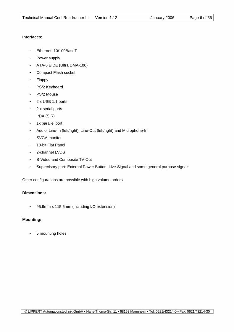
Interfaces:
- Ethernet: 10/100BaseT
- Power supply
- ATA-6 EIDE (Ultra DMA-100)
- Compact Flash socket
- Floppy
- PS/2 Keyboard
- PS/2 Mouse
- 2 x USB 1.1 ports
- 2 x serial ports
- IrDA (SIR)
- 1x parallel port
- Audio: Line-In (left/right), Line-Out (left/right) and Microphone-In
- SVGA monitor
- 18-bit Flat Panel
- 2-channel LVDS
- S-Video and Composite TV-Out
- Supervisory port: External Power Button, Live-Signal and some general purpose signals
Other configurations are possible with high volume orders. Dimensions:
- 95.9mm x 115.6mm (including I/O extension) Mounting:
- 5 mounting holes

Technical Manual Cool Roadrunner III Version 1.12 January 2006 Page 7 of 35
© LIPPERT Automationstechnik GmbH • Hans-Thoma-Str. 11 • 68163 Mannheim • Tel: 0621/43214-0 • Fax: 0621/43214-30
1.2 Functional Block Diagram
Intel ULVCeleron
---------------Intel LV
Pentium-III
VIA VT8606Northbridge
EthernetController
VIA VT82C686BSouthbridge
BIOS AudioCodecWatchdog
SDRAM(SODIMM)
ISA Bus
PCI Bus
EIDEUltra DMA/100
COM 1 COM 2LPT 1 KB
SVGA10/100 BaseT Flat Panel
Floppy
2xU
SB /
Aud
io /
Mou
se /
IrDA
PC/104 Bus
PC/104 Plus Bus
CompactFlash Socket
Supervisory
2x LVDS TV-Out
TV-Encoder
CPU TempSensing

Technical Manual Cool Roadrunner III Version 1.12 January 2006 Page 8 of 35
© LIPPERT Automationstechnik GmbH • Hans-Thoma-Str. 11 • 68163 Mannheim • Tel: 0621/43214-0 • Fax: 0621/43214-30
1.3 Processor Using Intel’s advanced 0.13-micron process technology with copper interconnect, both the ULV Celeron and. the LV Pentium-III processor offers high-performance and low-power consumption. They are based on the same core as existing Mobile Intel® Pentium® III Processor-M. Key performance features include MMX® technology, Internet Streaming SIMD instructions, an Advanced Transfer Cache architecture, Dynamic Exe-cution and a processor system bus speed of 100 MHz (Pentium-III: 133MHz). The integrated L2 cache based on the Advanced Transfer Cache architecture runs at full speed and is designed to help improve per-formance. It complements the system bus by providing critical data faster and reducing total system power consumption. The processor also features Data Prefetch Logic that speculatively fetches data to the L2 cache, resulting in improved performance. The processor’s 64-bit wide Assisted Gunning Transceiver Logic (AGTL) system bus provides a glue-less, point-to-point interface to the Northbridge.
1.4 Northbridge – VIA TwisterT TwisterT is a high performance and energy efficient SMA chipset which connects to the CPU through a 64-bit, 100MHz (Pentium-III: 133MHz) Front Side Bus (FSB). It comprises the system controller, S3’s Savage4 2D/3D graphics accelerator and S3’s flat panel interfaces. The TwisterT SMA system controller provides superior communication performance between the CPU, DRAM and PCI bus with pipelined, burst, and concurrent operation. The Synchronous DRAM interface al-lows zero wait state bursting between the DRAM and the data buffers at FSB frequency. TwisterT supports a 32-bit 3.3 / 5V system bus (PCI 2.2) that is synchronous / pseudo-synchronous to the CPU bus. The chip contains a built-in bus-to-bus bridge to allow simultaneous concurrent operations on each bus. TwisterT also contains S3’s Savage4 graphics accelerator. Featuring a new super-pipelined 128-bit engine, it utilizes a single cycle architecture that provides high performance along with superior image quality. Reso-lutions as high as 1600x1200 at 64K colors are supported. Several new features enhance the 3D architec-ture, including single-pass multitexturing, anisotropic filtering, and an 8-bit stencil buffer. For MPEG-2 (DVD) playback, TwisterT’s video accelerator offloads the CPU by performing the planar to packed format conver-sion and motion compensation tasks, while its enhanced scaling algorithm delivers incredible full-screen video playback. TwisterT supports a wide variety of DSTN or TFT panels through an 18-bit interface. Alternatively a TV that conforms to the NTSC or the PAL standards can be connected. In addition, the integrated 2-channel LVDS interface can support another panel.
1.5 Southbridge – VIA VT82C686 The VT82C686B “PCI Super-I/O Integrated Peripheral Controller” is a high integration, high performance, power-efficient, and high compatibility device. In addition to complete ISA extension bus functionality, the VT82C686B includes the following standard intelligent peripheral controllers:
- Master mode enhanced IDE controller with dual channel DMA engine and interlaced dual channel commands. The VT82C686B supports data transfer rates up to 100MB/s through the UltraDMA-100 (ATA-6) standard.
- Standard floppy disk drive interface
- Keyboard controller and PS/2 mouse support.
- Universal Serial Bus controller with two ports that are USB v1.1 and Universal HCI v1.1 compliant.
- Two 16550-compatible serial I/O ports and infrared communications port option

Technical Manual Cool Roadrunner III Version 1.12 January 2006 Page 9 of 35
© LIPPERT Automationstechnik GmbH • Hans-Thoma-Str. 11 • 68163 Mannheim • Tel: 0621/43214-0 • Fax: 0621/43214-30
- ECP/EPP-capable parallel port
- Integrated PCI-mastering full-duplex direct-sound AC97 sound system. Hardware SoundBlaster Pro and hardware-assisted FM blocks are included for Windows DOS box and real-mode DOS compati-bility.
- Power management functionality compliant with ACPI and legacy APM requirements. Multiple sleep
states (Power-on Suspend, Suspend-to-RAM (STR) and Suspend-To-Disk) are supported with hard-ware automatic wake-up.
- Hardware monitoring subsystem for managing system voltage levels and CPU fan speed
1.6 PC/104-Plus Bus Interface The PC/104-Plus bus is a modification of the standard PCI bus. It incorporates all of the PC/104 features, with the added advantage of the high speed PCI bus. The main features are:
- PC/104 Plus Bus slot fully compatible with PCI version 2.2 specifications.
- Integrated PCI arbitration interface (32 bit wide, 3.3V and 5V).
- Translation of PCI cycles to ISA bus.
- Translation of ISA master initiated cycle to PCI.
- Support for burst read/write from PCI master.
- 33 MHz PCI clock.
Note: The internal DC/DC converter does not supply the 3.3 Volts pins to the PC/104-Plus bus.
1.7 PC/104 Bus Interface The PC/104 bus is a modification of the industry standard (ISA) PC bus specified in IEEE P996. The PC/104 bus has different mechanics than P966 to allow the stacking of modules. The main features are:
- Supports programmable extra wait state for ISA cycles.
- Supports I/O recovery time for back-to-back I/O cycles. The specifications for the PC/104 bus and the PC/104-Plus bus are available from the PC/104 Consortium at http://www.pc104.org.
1.8 National MacPhyter Ethernet Controller The National Semiconductor MacPhyter is a fully integrated 10/100 Base-TX LAN solution and consists of both the Media Access Controller and the physical layer interface combined into a single component solu-tion. The 32-bit PCI v2.2 controller provides enhanced scatter-gather bus mastering capabilities and enables the MacPhyter to perform high-speed data transfers over the PCI bus. Its bus master capabilities enable the

Technical Manual Cool Roadrunner III Version 1.12 January 2006 Page 10 of 35
© LIPPERT Automationstechnik GmbH • Hans-Thoma-Str. 11 • 68163 Mannheim • Tel: 0621/43214-0 • Fax: 0621/43214-30
component to process high level commands and perform multiple operations, which lowers CPU utilization by off-loading communication tasks from the CPU: two large transmit and receive FIFOs of 2 KB each help to prevent data underrun and overrun while waiting for bus accesses. This enables the MacPhyter to transmit data with minimum interframe gap. The CSMA/CD unit of the MacPhyter allows it to be connected to either a 10 or 100 Mbps Ethernet network. The CSMA/CD unit performs all of the functions of the 802.3 protocol such as frame formatting, frame strip-ping, collision handling, deferral to link traffic, etc. The CSMA/CD unit can also be placed in a full duplex mode, which allows simultaneous transmission and reception of frames. In full duplex mode it adheres to the IEEE 802.3x Flow Control specification. The PHY unit of the MacPhyter supports Auto-Negotiation for 10BaseT-/100BaseTX Half Duplex and 10BaseT-/100BaseTX Full Duplex modes. The signals of the Ethernet interface are located on the IDC10 header “Ethernet”. An adapter cable from IDC10 to RJ45 connector is available.
1.9 Watchdog A watchdog is implemented by a Maxim 691 Reset/Watchdog circuit. It is accessible through some general-purpose ports of the Southbridge controller: setting bit 0 of port 404Ch to 1 enables the watchdog function. Thereafter the watchdog must be triggered within 600ms; otherwise the watchdog generates a full hardware reset. Toggling bit 1 of port 404Dh triggers the watchdog. The status of the watchdog can either be read through port 4048h (bit 7) or be determined from pin 3 of the supervisory connector (WD-ACTIVE). In each case a high level indicates, that a watchdog time-out has oc-curred. Additionally a red LED lights up, which is located on the topside of the board.
1.10 CPU Temperature Control The Intel processors contain a temperature sensor to monitor the CPU temperature. The current temperature is shown in the PC Health Status screen of BIOS setup. It is measured directly under the SODIMM RAM socket. The measurement has an accuracy of ±3°C. There is also a feature in the PC Health Status screen, which enables throttling of the CPU speed, if a se-lectable temperature limit is exceeded. It is called Shutdown Temperature and it can be set to 75°C, 85°C or 95°C or it can be completely disabled (default). The Cool RoadRunner III variants up to 650 MHz do not need a cooling fan at the standard environment temperatures from –20°C…+60°C. It should be noted, however, that the provided passive heatsink can reach a temperature of +80°C. This is normal behavior and the CPU's maximum die temperature of 100°C is not exceeded if that happens.
The provided passive heatsink is a rather large device and may cause mechanical problems in certain sys-tem environments. In that case the customer must develop his own approach to cooling. This might be a specially built heatsink, a heatpipe, a Peltier element or something else.
The 933 MHz variant does always need a CPU fan (or some other active cooling device, such as a heat pipe) in order to keep the temperature below the maximum allowed value.
Caution! The Cool RoadRunner III must always be operated with proper cooling provisions. Warranty will be void if operated without cooling.

Technical Manual Cool Roadrunner III Version 1.12 January 2006 Page 11 of 35
© LIPPERT Automationstechnik GmbH • Hans-Thoma-Str. 11 • 68163 Mannheim • Tel: 0621/43214-0 • Fax: 0621/43214-30
1.11 On Board Power Supply The on board power supply generates all necessary voltages from the single supply voltage of 5 volts. The voltages are observed by the Southbridge and are shown in the PC Health Status screen of BIOS setup. The generated voltage of 3.3 Volts is available on the connectors “Flat Panel“ and “LVDS“.
Note: This 3.3 V must not be used to supply external electronic devices with high power consumption like other PC/104 boards or displays.
1.12 EIDE Port An EIDE (Enhanced Integrated Drive Electronics) port is provided by the chipset to connect up to two drives that integrate the controller (hard disk, CD-ROM etc.). To enhance the performance, this port supports Ultra DMA-100 type of transfer. The EIDE port is available on a standard 44-pin header (2mm) for 2,5” hard disks. An adapter cable is available to connect standard EIDE devices with a 40 pin IDC header.
1.13 Compact Flash connector On the bottom side of the board a compact flash connector is located that allows the use of compact flash cards instead of a hard disk. This socket is connected to the secondary EIDE port of the chipset. Compact flash cards are available as solid-state disks starting at 16 Mbytes up to several Gbytes and also as IBM MicroDrives.
1.14 Floppy Disk Interface The floppy interface connector is built for slimline floppy disk drives. For connection of a conventional floppy disk drive an optional adapter connector is available.
1.15 PS/2 Keyboard Interface The keyboard interface is located on the IDC10 Header “KEYBOARD”. An adapter cable is available to use a standard PS/2 keyboard with this connector.
1.16 PS/2 Mouse Interface The PS/2 mouse signals MCLK and MDAT are located on the IDC16 header “AUDIO”. The PS/2 mouse function is programmable in BIOS setup by pressing DEL at boot time. PS/2 mouse function control can be enabled or disabled in the Advanced BIOS features menu.
1.17 USB 1.1 Ports Two USB 1.1 ports are located on the IDC16 header “AUDIO”. When using USB it has to be enabled in BIOS setup by entering Advanced Chipset Features and then choosing OnChip USB: Enabled.

Technical Manual Cool Roadrunner III Version 1.12 January 2006 Page 12 of 35
© LIPPERT Automationstechnik GmbH • Hans-Thoma-Str. 11 • 68163 Mannheim • Tel: 0621/43214-0 • Fax: 0621/43214-30
It is possible to use an USB keyboard under MSDOS without special driver software*. To do so, USB legacy support has to be enabled in the BIOS. Entering Advanced Chipset Features and then selecting USB Keyboard support: Enabled does this setting. An adapter cable with two standard USB connectors is available. *Note: not all keyboard manufacturers are supported.
1.18 Serial Port COM1 And COM2 The serial ports are located on two IDC headers “COM1” and “COM2”. Adapter cables with standard DB9 male connectors are available. The serial ports are programmable in BIOS setup by pressing DEL at boot time. When entering Integrated Peripherals and then choosing Onboard Serial Port 1 or Onboard Serial Port 2, configuration of the serial ports is accessible. The following settings are possible for COM1 and COM2, respectively:
- Auto - Disabled - 3F8 / IRQ4 (base address / interrupt channel) - 2F8 / IRQ3 (base address / interrupt channel) - 3E8 / IRQ4 (base address / interrupt channel) - 2E8 / IRQ3 (base address / interrupt channel)
1.19 IrDA Interface The IrDA interface signals IRRX and IRTX are located on the IDC16 header “AUDIO”. The IrDA interface is available as serial port 2 by selecting it in the BIOS setup. The normal serial port 2 cannot be used at the same time as the IrDA interface. Entering Integrated Peripherals and then choosing Auto or one of the available base addresses in the menu point Serial Port 2, the submenu UART2 Mode will appear. There are three different possibilities to choose from: - Standard (= normal function of COM2) - HPSIR - ASK-IR When HPSIR or ASK-IR is selected, the duplex mode can be changed between half and full duplex via the submenu Duplex Select. To use the IrDA interface an external transmitter must be connected to the IrDA signals.
1.20 Parallel Port LPT1 The parallel port is located on an IDC26 header. An adapter cable with a standard DB25 female connector is available. The parallel port is programmable in the BIOS setup. The configuration of LPT1 is accessible by entering Integrated Peripherals and then choosing Onboard Parallel Port. The following settings are possible:
- Disabled - 3BC/IRQ7 (base address / interrupt channel) - 378/IRQ7 (base address / interrupt channel)

Technical Manual Cool Roadrunner III Version 1.12 January 2006 Page 13 of 35
© LIPPERT Automationstechnik GmbH • Hans-Thoma-Str. 11 • 68163 Mannheim • Tel: 0621/43214-0 • Fax: 0621/43214-30
- 278/IRQ5 (base address / interrupt channel)
When Onboard Parallel Port is not disabled, the Parallel Port Mode can be selected: - Normal - ECP - EPP - EPP + ECP
If Parallel Port Mode is switched to ECP or EPP + ECP, ECP Mode Use DMA is accessible. DMA channels 1 or 3 can be selected. If EPP or EPP + ECP is chosen, Parallel Port EPP Type can be set to EPP1.7 or EPP1.9.
1.21 Audio Interface The audio signals are located on the IDC16 header “AUDIO”. The signals are LINE-IN (left/right), LINE-OUT (left/right) and MICROPHONE-IN of the AC-97 Audio Codec. For using sound under MS-DOS, legacy audio support has to be enabled in the BIOS setup. To achieve this, Onboard Legacy Audio in the submenu In-tegrated Peripherals has to be set to “Enabled”. Then the following submenus are also accessible: Sound Blaster: Enabled, Disabled
SB I/O Base Address: 220h, 240h, 260h or 280h SB IRQ Select: IRQ5, IRQ7, IRQ9 or IRQ10 SB DMA Select: DMA0, DMA1, DMA2 or DMA3
MPU-401: Enabled, Disabled MPU-401 I/O Base Address: 300h, 310h, 320h or 330h Driver packages for MS-Windows are available. There is an adapter cable available with standard audio connectors.
1.22 Speaker The speaker signal is located on the IDC10 Header “KEYBOARD”. A standard PC Speaker can be con-nected between the signal SPEAKER and VCC.
1.23 SVGA Port The SVGA connector is located on a 10-pin IDC header. An adapter cable to Sub-D HD15 female for CRT Monitors is available. The following display modes are supported:
Resolution Color (bpp) Max. Refresh rate (Hz) 640x480 8/16/32 160 800x600 8/16/32 85 1024x768 8/16/32 130
1280x1024 8/16/32 100 1600x1200 8/16 60

Technical Manual Cool Roadrunner III Version 1.12 January 2006 Page 14 of 35
© LIPPERT Automationstechnik GmbH • Hans-Thoma-Str. 11 • 68163 Mannheim • Tel: 0621/43214-0 • Fax: 0621/43214-30
1.24 Flat Panel Port The Flat panel port supports 8-bit and 16-bit DSTN displays and 9-bit, 12-bit, 15-bit and 18-bit TFT displays. The signals are provided through an IDC 30 header, which is located on the bottom side of the board. Next to it the backlight connector (Hirose DF13-8P) is mounted. The supply voltages of the backlight converter and of the display can be switched over the board. This is necessary for the correct power-on sequence of some displays. Furthermore these voltages can be adjusted in value by the display voltage selector (see chapter 3). The Panel type can be selected using the BIOS setup utility, in Advanced Chipset Features. Additionally the Display Device in the same submenu has to be set to LCD or CRT+LCD to activate the flat panel port. The following TFT display types are supported:
The following DSTN display types are supported:
Note: The TV-Out port cannot be used at the same time as the Flat Panel port.
Resolution Panel Type 640x480 0 800x600 9 1024x768 A
1280x1024 3 or B
Resolution Panel Type 640x480 4 800x600 5 or D 1024x768 E
1280x1024 F

Technical Manual Cool Roadrunner III Version 1.12 January 2006 Page 15 of 35
© LIPPERT Automationstechnik GmbH • Hans-Thoma-Str. 11 • 68163 Mannheim • Tel: 0621/43214-0 • Fax: 0621/43214-30
1.25 LVDS Port A 20 pin Hirose DF14 connector provides a 1- or 2-channel LVDS interface. The supply voltages of the back-light converter and of the display can be switched over the board. This is necessary for the correct power-on sequence of some displays. Furthermore these voltages can be adjusted in value by the display voltage selector (see chapter 3). The Panel type can be selected in the Advanced Chipset Features of BIOS setup. Additionally the Display Device in the same submenu has to be set to LCD or CRT+LCD to activate the flat panel port. The following LVDS display types are supported:
Note that a single channel interface uses only the Y (see pin definitions in chapter 3) outputs; a dual channel uses both, the Y and the Z outputs.
1.26 TV-out Port The TV-out port offers the possibility to directly connect a TV to the Cool Road Runner 3. The TV standards supported are PAL, NTSC and NTSC-J (Japan). A 6-pin Hirose DF-13 header on the bottom side of the board provides composite and S-Video signals. The TV type can be selected in the Advanced Chipset Features of BIOS setup. Additionally the Display Device in the same submenu has to be set to TV or CRT+TV to activate the TV-out port.
Note: The TV-Out port cannot be used at the same time as the Flat Panel port.
Resolution Number of channels Panel Type 640x480 1 8 800x600 1 1 1024x768 2 6 1024x768 1 7
1400x1050 2 C

Technical Manual Cool Roadrunner III Version 1.12 January 2006 Page 16 of 35
© LIPPERT Automationstechnik GmbH • Hans-Thoma-Str. 11 • 68163 Mannheim • Tel: 0621/43214-0 • Fax: 0621/43214-30
1.27 Supervisory Connector The Cool RoadRunner III provides a 15-pin Supervisory Connector on its bottom side. Besides several gen-eral purpose signals (see table below) it delivers misc. control and status signals:
- Watchdog active: high when the watchdog was triggered
- Live signal: user-programmable “application running” signal
- External Power Button: an impulse to GND (> 4 s) on this signal switches the system to the “Soft-off” state. Another impulse (> 100 ms) turns it on again.
- The following table shows the general purpose signals and explains how to control them:
Pin Direction Enable 5V tolerant Value (Note 1) 4 Output - - I/O 404E[6]
6 Input - no I/O 4048[2]
7 Input - yes I/O 4048[1]
8 Input - yes I/O 4048[6]
9 Input - yes I/O 404A[6]
10 Input - yes I/O 404A[7]
11 Input Note 2 yes I/O 4049[3]
11 Output Note 2 - I/O 404D[3]
12 Output - - I/O 404C[5]
13 Output Note 3 - I/O 404D[4]
14 Output - - Note 4
Notes: 1) I/O xxxx[n] means Bit n of I/O Port xxxx 2) Pin 11 can be used as an input or as an output port. To switch between these
modes, first write address 80003874h to Port CF8h. Then writing a 0 to bit 5 of Port CFCh results in pin 11 being an input, while writing a 1 to this bit config-ures it as an output.
3) Pin 13 must be enabled before it can be used. To do so write address 80003874h to Port CF8h. Then write a 1 to Bit 17 of port CFCh.
4) To set the value of pin 14, first write 0Dh to Port 3C4h. Then the value can be controlled by bit 0 of Port 3C5h.
1.28 Reset-In Signal The RESET-IN signal is located on the IDC10 Header “KEYBOARD”. To reset the board the signal RESET-IN must be connected to GND.

Technical Manual Cool Roadrunner III Version 1.12 January 2006 Page 17 of 35
© LIPPERT Automationstechnik GmbH • Hans-Thoma-Str. 11 • 68163 Mannheim • Tel: 0621/43214-0 • Fax: 0621/43214-30
2 Hardware Installation The Cool RoadRunner III is delivered with jumper settings for proper operation. The customer must not change the default jumper settings. Improper jumper settings will cause system instability or system hang-ups.
Caution!
The board must not be connected or disconnected to PC/104 bus or PC/104Plus bus with power supply switched ON!
2.1 Adapter Cable Set With the optional available cable set standard PC devices can be easily connected to the board. The adapter cable set comprises the following items: - Adapter cable 3.5’’ power supply connector female to 5.25’’ power supply connector male for supplying
the board with a standard PC power supply - Two adapter cables IDC10 female to DB9 male for serial port 1 and 2 - Adapter cable IDC26 female to DB25 female for parallel port - Adapter cable IDC10 female to DB9 female plus adapter to SUB-D 15p. female for standard VGA moni-
tors - Adapter cable IDC44 / 2mm female to IDC44 / 2mm female to connect 2.5’’ EIDE hard disks - Flat foil cable 26p. plus PCB adapter to 34p. female 2 row 2.54mm grid The flat foil cable must be inserted in the FFC connector with the blank side on the top. Be careful not to damage the little safety lever at the floppy connector.

Technical Manual Cool Roadrunner III Version 1.12 January 2006 Page 18 of 35
© LIPPERT Automationstechnik GmbH • Hans-Thoma-Str. 11 • 68163 Mannheim • Tel: 0621/43214-0 • Fax: 0621/43214-30
3 Software
3.1 BIOS The Cool RoadRunner III is delivered with a standard PC BIOS. The default setting guarantee a “ready to run” system, even without a BIOS setup backup battery. If the user wants to change settings, pressing the <DEL> key on power up accesses the setup utility. The BIOS is located in a flash prom and can be easily updated on board with software under DOS. All changes in the setup of the BIOS are stored in the CMOS RAM of the real time clock. A copy of the CMOS RAM excluding date and time data is stored in the flash ROM. This means that even if the backup battery runs out of power, the CMOS settings are not lost. Only date and time will be set to their default value. The default values of the BIOS can be automatically loaded at boot time. To achieve this, the key “0 / INSERT” on the numerical keypad should be pressed before the system is turned on. Holding this key and turning the system on loads the default values.
3.2 Drivers Software drivers for Sound, Ethernet, graphics adapter as well as for the VIA chipset are available for the Cool RoadRunner III. These drivers can be downloaded from LiPPERT's website http://www.lippert-at.com. For installation follow the instructions on the driver disks.

Technical Manual Cool Roadrunner III Version 1.12 January 2006 Page 19 of 35
© LIPPERT Automationstechnik GmbH • Hans-Thoma-Str. 11 • 68163 Mannheim • Tel: 0621/43214-0 • Fax: 0621/43214-30
4 Connector Definitions Refer to chapter 5.2 Mechanical specifications for an overview of the connector positions.
4.1 PC104-Plus Bus Pin A B C D
1 GND Reserved +5 Volts AD00 2 VI/O AD02 AD01 +5 Volts 3 AD05 GND AD04 AD03 4 C/BE0 AD07 GND AD06 5 GND AD09 AD08 GND 6 AD11 VI/O AD10 M66EN 7 AD14 AD13 GND AD12 8 NC C/BE1 AD15 NC 9 SERR GND SB0 PAR 10 GND PERR NC SDONE 11 STOP NC LOCK GND 12 NC TRDY GND DEVSEL 13 FRAME GND IRDY NC 14 GND AD16 NC C/BE2 15 AD18 NC AD17 GND 16 AD21 AD20 GND AD19 17 NC AD23 AD22 NC 18 IDSEL0 GND IDSEL IDSEL2 19 AD24 C/BE3 VI/O IDSEL3 20 GND AD26 AD25 GND 21 AD29 +5 Volts AD28 AD27 22 +5 Volts AD30 GND AD31 23 REQ0 GND REQ1 VI/O 24 GND REQ2 +5 Volts GNT0 25 GNT1 VI/O GNT2 GND 26 +5 Volts CLK0 GND CKL1 27 CLK2 +5 Volts CLK3 GND 28 GND INTD +5 Volts RST 29 +12 Volts INTA INTB INTC 30 -12 Volts Reserved Reserved GND
Note: All VIO pins are connected to +5 Volts by default. This board does not support -12 Volts.

Technical Manual Cool Roadrunner III Version 1.12 January 2006 Page 20 of 35
© LIPPERT Automationstechnik GmbH • Hans-Thoma-Str. 11 • 68163 Mannheim • Tel: 0621/43214-0 • Fax: 0621/43214-30
4.2 PC/104 Bus
Pin A B 1 IOCHCK GND 2 D7 RSTDRV 3 D6 +5 Volts 4 D5 IRQ9 5 D4 -5 Volts 6 D3 DRQ2 7 D2 -12 Volts Pin D C 8 D1 ENDXFR 0 GND GND 9 D0 +12 Volts 1 MEMCS16 SBHE 10 IOCHRDY KEY 2 IOCS16 LA23 11 AEN SMEMW 3 IRQ10 LA22 12 A19 SMEMR 4 IRQ11 LA21 13 A18 IOW 5 IRQ12 LA20 14 A17 IOR 6 IRQ15 LA19 15 A16 DACK3 7 IRQ14 LA18 16 A15 DRQ3 8 DACK0 LA17 17 A14 DACK1 9 DRQ0 MEMR 18 A13 DRQ1 10 DACK5 MEMW 19 A12 REFRESH 11 DRQ5 SD8 20 A11 SYSCLK 12 DACK6 SD9 21 A10 IRQ7 13 DRQ6 SD10 22 A9 IRQ6 14 DACK7 SD11 23 A8 IRQ5 15 DRQ7 SD12 24 A7 IRQ4 16 +5 Volts SD13 25 A6 IRQ3 17 MASTER SD14 26 A5 DACK2 18 GND SD15 27 A4 TC 19 GND GND 28 A3 BALE 29 A2 +5 Volts 30 A1 OSC 31 A0 GND 32 GND GND -5 Volts and –12 Volts are not supported on this board.

Technical Manual Cool Roadrunner III Version 1.12 January 2006 Page 21 of 35
© LIPPERT Automationstechnik GmbH • Hans-Thoma-Str. 11 • 68163 Mannheim • Tel: 0621/43214-0 • Fax: 0621/43214-30
4.3 10/100BaseT Connector Connector type: IDC10 pin header 2.54 mm
Signal name Pin Signal name Pin TX+ 1 TX- 2 RX+ 3 PE 4 PE 5 RX- 6
4.4 EIDE Connector Connector type: IDC14 pin header 2.00 mm
Signal name Pin Signal name Pin /Reset 1 GND 2 Data7 3 Data8 4 Data6 5 Data9 6 Data5 7 Data10 8 Data4 9 Data11 10 Data3 11 Data12 12 Data2 13 Data13 14 Data1 15 Data14 16 Data0 17 Data15 18 GND 19 NC 20 DRQ0 21 GND 22 Write 23 GND 24 Read 25 GND 26 Ready 27 CSEL 28 DACK0 29 GND 30 IRQ 31 IOCS16- 32 Address1 33 PD66 34 Address0 35 Address2 36 CS1 37 CS3 38 NC 39 GND 40 +5 Volts 41 +5 Volts 42 GND 43 GND 44
4.5 Power Connector Connector type: 3.5” FDD Power connector
Signal name Pin Signal name Pin +5 Volts 1 GND 2 GND 3 + 12 Volts 4
Technical Manual Cool Roadrunner III Version 1.12 January 2006 Page 22 of 35
© LIPPERT Automationstechnik GmbH • Hans-Thoma-Str. 11 • 68163 Mannheim • Tel: 0621/43214-0 • Fax: 0621/43214-30
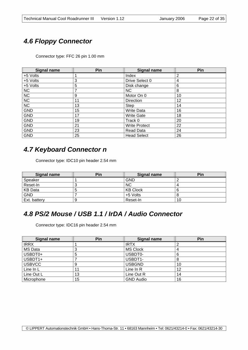
4.6 Floppy Connector Connector type: FFC 26 pin 1.00 mm
Signal name Pin Signal name Pin +5 Volts 1 Index 2 +5 Volts 3 Drive Select 0 4 +5 Volts 5 Disk change 6 NC 7 NC 8 NC 9 Motor On 0 10 NC 11 Direction 12 NC 13 Step 14 GND 15 Write Data 16 GND 17 Write Gate 18 GND 19 Track 0 20 GND 21 Write Protect 22 GND 23 Read Data 24 GND 25 Head Select 26
4.7 Keyboard Connector n Connector type: IDC10 pin header 2.54 mm
Signal name Pin Signal name Pin Speaker 1 GND 2 Reset-In 3 NC 4 KB Data 5 KB Clock 6 GND 7 +5 Volts 8 Ext. battery 9 Reset-In 10
4.8 PS/2 Mouse / USB 1.1 / IrDA / Audio Connector Connector type: IDC16 pin header 2.54 mm
Signal name Pin Signal name Pin IRRX 1 IRTX 2 MS Data 3 MS Clock 4 USBDT0+ 5 USBDT0- 6 USBDT1+ 7 USBDT1- 8 USBVCC 9 USBGND 10 Line In L 11 Line In R 12 Line Out L 13 Line Out R 14 Microphone 15 GND Audio 16

Technical Manual Cool Roadrunner III Version 1.12 January 2006 Page 23 of 35
© LIPPERT Automationstechnik GmbH • Hans-Thoma-Str. 11 • 68163 Mannheim • Tel: 0621/43214-0 • Fax: 0621/43214-30
4.9 COM1 Connector Connector type: IDC10 pin header 2.54 mm
Signal name Pin Signal name Pin DCD 1 DSR 2 RXD 3 RTS 4 TXD 5 CTS 6 DTR 7 RI 8 GND 9 +5 Volts 10
4.10 COM2 Connector Connector type: IDC10 pin header 2.54 mm
Signal name Pin Signal name Pin DCD 1 DSR 2 RXD 3 RTS 4 TXD 5 CTS 6 DTR 7 RI 8 GND 9 +5 Volts 10
4.11 LPT1 Connector Connector type: IDC26 pin header 2.54 mm
Signal name Pin Signal name Pin Strobe 1 Auto LF 2 Data0 3 Error 4 Data1 5 Init 6 Data2 7 Select In 8 Data3 9 GND 10 Data4 11 GND 12 Data5 13 GND 14 Data6 15 GND 16 Data7 17 GND 18 ACK 19 GND 20 Busy 21 GND 22 Paper End 23 GND 24 Select 25 NC 26
Technical Manual Cool Roadrunner III Version 1.12 January 2006 Page 24 of 35
© LIPPERT Automationstechnik GmbH • Hans-Thoma-Str. 11 • 68163 Mannheim • Tel: 0621/43214-0 • Fax: 0621/43214-30
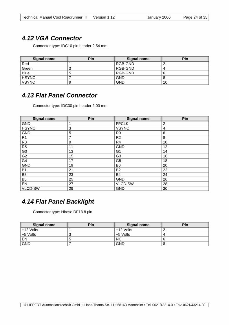
4.12 VGA Connector Connector type: IDC10 pin header 2.54 mm
Signal name Pin Signal name Pin Red 1 RGB-GND 2 Green 3 RGB-GND 4 Blue 5 RGB-GND 6 HSYNC 7 GND 8 VSYNC 9 GND 10
4.13 Flat Panel Connector Connector type: IDC30 pin header 2.00 mm
Signal name Pin Signal name Pin GND 1 FPCLK 2 HSYNC 3 VSYNC 4 GND 5 R0 6 R1 7 R2 8 R3 9 R4 10 R5 11 GND 12 G0 13 G1 14 G2 15 G3 16 G4 17 G5 18 GND 19 B0 20 B1 21 B2 22 B3 23 B4 24 B5 25 GND 26 EN 27 VLCD-SW 28 VLCD-SW 29 GND 30
4.14 Flat Panel Backlight Connector type: Hirose DF13 8 pin
Signal name Pin Signal name Pin +12 Volts 1 +12 Volts 2 +5 Volts 3 +5 Volts 4 EN 5 NC 6 GND 7 GND 8

Technical Manual Cool Roadrunner III Version 1.12 January 2006 Page 25 of 35
© LIPPERT Automationstechnik GmbH • Hans-Thoma-Str. 11 • 68163 Mannheim • Tel: 0621/43214-0 • Fax: 0621/43214-30
4.15 LVDS Connector Connector type: Hirose DF14 20-pin header
Signal name Pin Signal name Pin Y0P 1 Y0M 2 Y1P 3 Y1M 4 Y2P 5 Y2M 6 YCP 7 YCM 8 Z0P 9 Z0M 10 Z1P 11 Z1M 12 Z2P 13 Z2M 14 ZCP 15 ZCM 16 GND 17 GND 18 VLCD-SW 19 VLCD-SW 20
4.16 Display Voltage Selector Connector type: IDC6 pin header 2.00 mm. Use a 2mm jumper between 1-3 or 3-5 to select the dis-play voltage. Use a 2mm jumper between 2-4 or 4-6 to select the backlight voltage.
Signal name Pin Signal name Pin +3.3 volts 1 +12 volts 2 display voltage 3 backlight voltage 4 +5 volts 5 + 5 volts 6
4.17 TV-OUT Connector Connector type: Hirose DF13 6-pin header
Signal name Pin Signal name Pin COMPOSITE 1 GND 2 CROMA 3 GND 4 LUMA 5 GND 6

Technical Manual Cool Roadrunner III Version 1.12 January 2006 Page 26 of 35
© LIPPERT Automationstechnik GmbH • Hans-Thoma-Str. 11 • 68163 Mannheim • Tel: 0621/43214-0 • Fax: 0621/43214-30
4.18 Supervisory Connector Connector type: Hirose DF13 15-pin
Signal name Pin Signal name Pin +5 Volts 1 +3.3 Volts 2 WD-ACTIVE 3 LIVE 4 PWR_BTN 5 GPI2 6 GPI1 7 GPI6 8 GPI22 9 GPI23 10 GPIOD 11 GPO5 12 GPO12 13 NB_GPOUT 14 GND 15
Note: The 3,3 Volts are generated by an on-board DC-DC converter. It must be not used to supply power to any peripherals with high power consumption.

Technical Manual Cool Roadrunner III Version 1.12 January 2006 Page 27 of 35
© LIPPERT Automationstechnik GmbH • Hans-Thoma-Str. 11 • 68163 Mannheim • Tel: 0621/43214-0 • Fax: 0621/43214-30
5 System Address Map This section describes the layout of the CPU memory and I/O address spaces.
Note: Depending on enabled or disabled functions in the BIOS, other or more resources may be used
5.1 Memory Address Map Address Range
(Dec) Address Range (Hex) Size Description
1024K - 16384K 100000 - FFFFFF 15360K Extended Memory 960K - 1024K F0000 - FFFFF 64K System BIOS 848K - 960K D4000 - EFFFF 112K Unused 832K - 848K D0000 - D3FFF 16K Etherboot ROM 824K - 832K CE000 - CFFFF 8K Unused 768K - 824K C0000 - CDFFF 56K Graphics BIOS 736K - 768K B8000 - BFFFF 32K Monochrome Text Memory 704K - 736K B0000 - B7FFF 32K Color Text Memory 640K - 704K A0000 - AFFFF 64K Graphic Memory
0K - 640K 0 - 9FFFF 640K Conventional Memory
5.2 I/O Address Map The system chip set implements a number of registers in I/O address space. These registers occupy the following map in the I/O space.
Address Range (Hex) Size Description 0000 – 000F 16 bytes DMA Controller 1 (8237) 0020 – 0021 2 bytes Interrupt Controller 1 (8259) 0040 – 0043 4 bytes Timer Controller (8254) 0060 1 byte Keyboard Controller Data Byte 0061 1 byte Misc. Functions & Speaker Control 0064 1 byte Keyboard Controller Command, Status 0070, bit 7 1 bit NMI Enable 0070, bit6:0 7 bits Real Time Clock Address 0071 1 byte Real Time Clock Data 0072 – 0075 2 byte reserved 0080 1 byte reserved 0081 – 008F 15 bytes DMA Page Registers 0092 1 byte System Control 00A0 – 00A1 2 bytes Interrupt Controller 2 (8259) 00C0 – 00DE 31 bytes DMA Controller 1 (8237) 02F8 – 02FF 8 bytes Serial Port 2 0378 – 037F 8 bytes Parallel Port 1 (Standard & EPP) 03F0 – 03F1 2 bytes Super-I/O Configuration Registers 03F0 – 03F7 6 bytes Floppy Controller Registers 03F8 – 03FF 8 bytes Serial Port 1 0778 – 077A 3 bytes Parallel Port 1 (ECP Extensions) 0CF8 – 0CFB 4 bytes PCI Configuration Address Register 0CFC – 0CFF 4 bytes PCI Configuration Data Registers

Technical Manual Cool Roadrunner III Version 1.12 January 2006 Page 28 of 35
© LIPPERT Automationstechnik GmbH • Hans-Thoma-Str. 11 • 68163 Mannheim • Tel: 0621/43214-0 • Fax: 0621/43214-30
5.3 Interrupts
IRQ System Resource NMI Parity Error
0 Timer 1 Keyboard 2 Interrupt Controller 2 3 Serial Port 2 4 Serial Port 1 5 available (PC/104 or -Plus) 6 Floppy 7 Parallel Port 1 8 Real Time Clock 9 available (PC/104 or -Plus) 10 available (PC/104 or -Plus) 11 available (PC/104 or -Plus) 12 PS/2 Mouse 13 Math coprocessor 14 EIDE 15 Compact Flash
5.4 DMA Channels DMA Data width System Resource
0 8 bits Available 1 8 bits Available 2 8 bits Floppy 3 8 bits Parallel Port 4 Reserved, Cascade Channel 5 16 bits IDE Controller 6 16 bits Available 7 16 bits Available

Technical Manual Cool Roadrunner III Version 1.12 January 2006 Page 29 of 35
© LIPPERT Automationstechnik GmbH • Hans-Thoma-Str. 11 • 68163 Mannheim • Tel: 0621/43214-0 • Fax: 0621/43214-30
6 Technical Characteristics
6.1 Electrical Supply voltage: +5 Volts Supply voltage ripple: ±3 % Supply current: depending on CPU frequency:
max. 2.8 A @ 400 MHz max. 3.3 A @ 650 MHz max. 3.9 A @ 933 MHz
6.2 Environmental Operating Temperature: -20…+60°C Storage temperature: -40...+70°C Temperature change: max. 10K / 30 minutes Humidity (relative): 10…90 % Pressure: 450...1100 hPa
Note: The passive heat sink can reach a temperature of +80°C. The maximum CPU temperature is not exceeded if this happens. To lower the system temperature the “Shutdown Temperature” feature can be enabled in BIOS setup. Notice that this throttles the CPU speed.
Caution! The Cool RoadRunner III must always be operated with proper cooling provisions. Warranty will be void if operated without cooling.

Technical Manual Cool Roadrunner III Version 1.12 January 2006 Page 30 of 35
© LIPPERT Automationstechnik GmbH • Hans-Thoma-Str. 11 • 68163 Mannheim • Tel: 0621/43214-0 • Fax: 0621/43214-30
6.3 MTBF MTBF at 30°C: 154.500 hours In order to perform a failure rate assessment, several assumptions have to be made to minimize the com-plexity of the analysis.
1. Basis for the calculation was „Parts-Stress“ method according to MIL-HDBK-217 F Notice 2. Al-though this method requires stress values for all components, mean stress values have been used.
2. Environmental factor „Ground Benign“ according to MIL-HDBK-217 has been used as well as an en-vironmental temperature of 30 °C.
3. Failure rate of mechanical components (screws, chassis, etc) is negligible. The detailed analysis report is available on request.
6.4 Mechanical Dimensions (LxW): 95.9mm x 115.6mm
(including I/O extension)
Height: 15mm Weight: 145g
(including SDRAM Module)

Technical Manual Cool Roadrunner III Version 1.12 January 2006 Page 31 of 35
© LIPPERT Automationstechnik GmbH • Hans-Thoma-Str. 11 • 68163 Mannheim • Tel: 0621/43214-0 • Fax: 0621/43214-30
Mechanical dimensions: Top side: Notes: - All dimensions are in inch - Values in brackets indicate the height of the
component marks Pin 1 marks Pin 2
Audio/USB
(.343)
Ethernet(.343)
VGA(.343)
IDE(.225)
Keyboard(.343)
PC/104 Plus Bus(.370)
COM 1(.343)
LPT(.343)
COM 2(.343)
PC/104 Bus(.450)
Ethernet ActivityEthernet 100M
bitEthernet Link
Watchdog Active
Live LEDID
E LED
Suspend Power
Pow
er On
STR Active
Northbridge(.097)
CPU(.109)
SDRAM (.220)
Power (.264)
LDO(.185)
LDO(.180)
AC-97(.063)
L(.150)
Fan(.185)
C's(.106)
D (.103)
C-
.2
70
.2
0
3.
94
0

Technical Manual Cool Roadrunner III Version 1.12 January 2006 Page 32 of 35
© LIPPERT Automationstechnik GmbH • Hans-Thoma-Str. 11 • 68163 Mannheim • Tel: 0621/43214-0 • Fax: 0621/43214-30
Bottom side: Notes: - All dimensions are in inch - Values in brackets indicate the height of the component marks Pin 1 marks Pin 2
Floppy(.118)
Supervisory(.142)
LVDS(.099)
Backlight(.142)
TV-Out(.142)
TFT(.240)
Display Voltages(.240)
PC/104 Bus(.394)
Compact Flash(.341) Southbridge
(.097)
BIOS(.180)
Clock
0.110
Net(.065)
Magnetics(.200)
C's(.106)C's
(.106)L
(.150)
CD
(.103)
Goldcap
(.220)
TV(.047)
PC/104 Plus Bus(.441)

Technical Manual Cool Roadrunner III Version 1.12 January 2006 Page 33 of 35
© LIPPERT Automationstechnik GmbH • Hans-Thoma-Str. 11 • 68163 Mannheim • Tel: 0621/43214-0 • Fax: 0621/43214-30
Self-stacking system (standard):
Customized system:

Technical Manual Cool Roadrunner III Version 1.12 January 2006 Page 34 of 35
© LIPPERT Automationstechnik GmbH • Hans-Thoma-Str. 11 • 68163 Mannheim • Tel: 0621/43214-0 • Fax: 0621/43214-30
7 Options The following accessories are available on request:
- Graphic driver software
- Ethernet driver software
- Sound driver software
- Compact flash cards
- Adapter cable set (including standard PC connectors for COM 1 and 2, LPT, Keyboard, flat foil cable adapter for 3,5” Floppy, VGA adapter cable, cable for 2,5’’ hard disk drives and Power supply)
- Adapter cable for Ethernet, Sound, USB, PS/2 Mouse The drivers can be downloaded from LiPPERT's website http://www.lippert-at.com

Technical Manual Cool Roadrunner III Version 1.12 January 2006 Page 35 of 35
© LIPPERT Automationstechnik GmbH • Hans-Thoma-Str. 11 • 68163 Mannheim • Tel: 0621/43214-0 • Fax: 0621/43214-30
8 Revision History
File name Date Edited by Changes
TME-104P-CRR3-R0V0.doc 2002-11-15 KF Created
TME-104P-CRR3-R0V0-PRE.doc
2003-02-04 KF preliminary version generated
TME-104P-CRR3-R1V0.doc 2003-02-13 PK Edited
TME-104P-CRR3-R1V1.doc 2003-07-30 KF/PK - 933 MHz CPU added - several updates & corrections - general editing
TME-104P-CRR3-R1V2.doc 2003-08-19 PK - minor textual corrections - heat sink temperature added
TME-104P-CRR3-R1V3.doc 2003-08-25 PK Cooling is required
TME-104P-CRR3-R1V4.doc 2003-10-06 PK Correct PC/104 bus definition, pin 6 is IRQ15
TME-104P-CRR3-R1V5.doc 2003-12-03 PK Correct USB connector description: use USBVCC and USBGND
TME-104P-CRR3-R1V6.doc 2004-01-12 KF Add description of GPIOs to chapter 1.27
TME-104P-CRR3-R1V7.doc 2004-03-16 KF - Change 3.3Volt pins in chapter 3.1 (PC/104+ connector) to NC - Delete note regarding 3.3Volts are on PC104+ bus in chapter 1.1 - Correct size of PCI-Bus arrow be- tween NB and SB in chapter 1.2 - Remove 2 Pixel/Clock modes from table in chapter 1.24
TME-104P-CRR3-R1V8.doc 2004-04-20 KF, PK - Add “1.1” to references to the USB port - Include MTBF data - New chapter 3, "Software"
TME-104P-CRR3-R1V9.doc 2004-06-21 KF - Add note regarding Shutdown temp- erature feature to chapter 6.2 - Chapter 1.27: completed table with pin 4 (Live signal) of Supervisory Connector
TME-104P-CRR3-R1V10.doc 2004-10-11 KF - adapted mechanical drawings to PCB ver-sion 3V0
TME-104P-CRR3-R1V11.doc 2005-01-10 KF - chapter 4.2: changed pin B10 of PC/104 bus to KEY (was GND/KEY) - chapter 4.12: corrected pin assignments of VGA connector - chapter 6.4: added some additional meas- urements to the top drawing
TME-104P-CRR3-R1V12.doc 2005-06-01 KF - chapter 5.1: Memory Address map cor-rected