Convolution and Filteringseisweb.usask.ca/.../2015/Lectures/PDF/8-Convolution.pdfGEOL 335.3 Digital...
15
GEOL 335.3 Digital Filtering Convolution of time series Convolution as filtering process Cross- and auto-correlation Frequency filtering Deconvolution Reading: ➢ Telford et al., Sections A.10,11
Transcript of Convolution and Filteringseisweb.usask.ca/.../2015/Lectures/PDF/8-Convolution.pdfGEOL 335.3 Digital...

GEOL 335.3
Digital Filtering
Convolution of time seriesConvolution as filtering processCross- and auto-correlationFrequency filteringDeconvolution
Reading:➢ Telford et al., Sections A.10,11

GEOL 335.3
Convolution of time series
Convolution for time (or space) series is what commonly is multiplication for numbers.Example of a ‘convolutional model’: rise in lake level resulting from rainfall
Let’s assume that the recorded rainfall over 5 months is: 2, 3, 1, 4, 3 cm, respectively.The lake level will respond to a 1 cm of rain fall, say, with a 2-cm rise in the first month and 1-cm in the second. This is called the ‘impulse response’. Lake level rises from the different months of rainfall will accumulate linearly.

GEOL 335.3
Lake Level Rise Numerical example
The resulting lake levels can be calculated by the following procedure, called convolution:
The impulse response series is reversed and shifted, and sample-by sample dot product is taken to find the response at any moment
GEOL 335.3
ConvolutionGeneral formulae
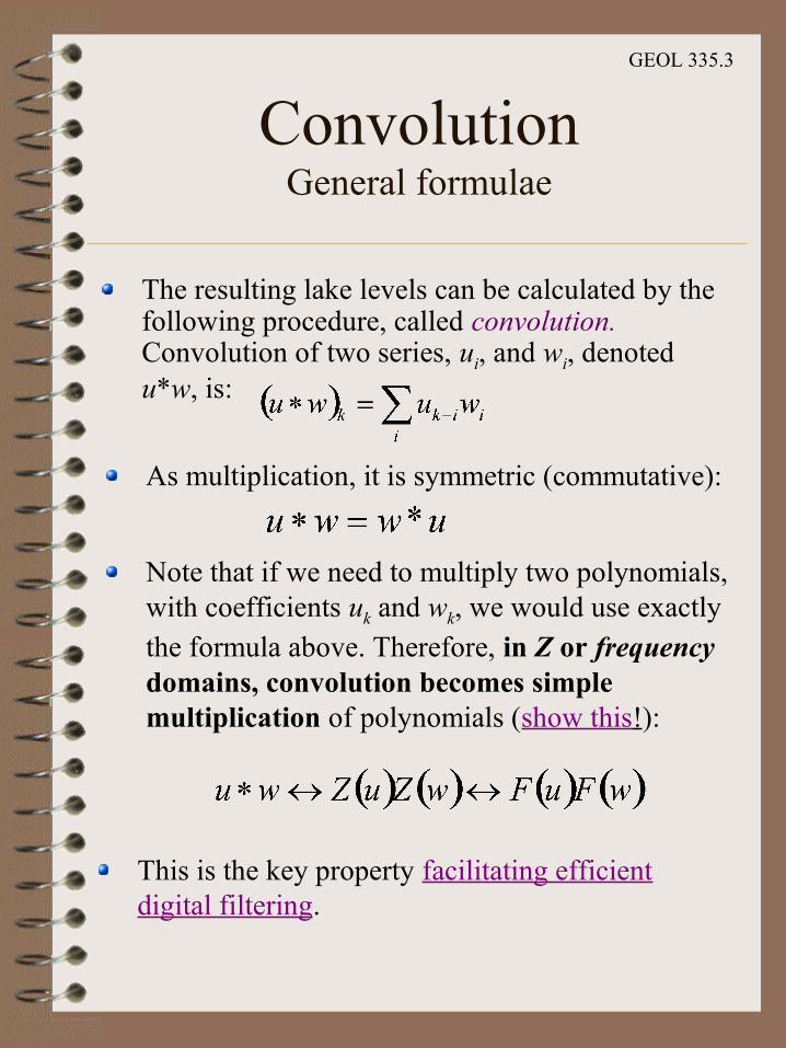
The resulting lake levels can be calculated by the following procedure, called convolution. Convolution of two series, ui, and wi, denoted u*w, is:
As multiplication, it is symmetric (commutative):
Note that if we need to multiply two polynomials, with coefficients uk and wk, we would use exactly the formula above. Therefore, in Z or frequency domains, convolution becomes simple multiplication of polynomials (show this!):
This is the key property facilitating efficient digital filtering.

GEOL 335.3
ConvolutionTwo important cases of interest
Digital signal filtering
Earth’s response is also a filter. Note that in this case, the impulse response is unknown and is of primary interest
Hence reflection processing deals with inverse filtering… (i.e., finding the filter)

GEOL 335.3
Convolutional modelof a reflection seismic record
Reflection seismic trace is a convolution of the source wavelet with the Earth's ‘reflectivity series’

GEOL 335.3
Convolutional modelA more realistic example
From
Yilm
az, 1
987

GEOL 335.3
Cross- and Auto-correlation
Cross-correlation gives the degree of similarity between two signals:
For each value of a ‘lag’ i:Shift the second trace by the lagCalculate dot product:
The lag for which the cross-correlation is largest gives the time shift between the two records
A most important application – pre-processing of Vibroseis recordings
Auto-correlation of a record is its cross-correlation with itself
It is symmetric in terms of positive and negative lagsIt indicates the degree to which the signal repeats itself.

GEOL 335.3
Linear Filtering
Most operations with seismic signals can be represented by a convolutional operator:
It is linear:
It is translationally (time-) invariant:
The filtering operator is represented differently in different domains:
Convolution in time domainComplex-value multiplication in Z- and frequency domains
This allows easy frequency filtering (selective enhancement or suppression of harmonic components in the signal)
v=F u
F u1u2=F u1F u2
F time shifted tu=time shifted tF u

GEOL 335.3
Frequency Filtering
Key element of seismic and GPR processing.Low-pass (high-cut), Band-pass, High-pass (low-cut), Notch
Suppressing the unwanted (noisy) parts of the frequency spectrum.
Usually zero-phase, to avoid phase (travel-time) distortion. This means that the filter does not change the phase spectrum.

GEOL 335.3
Filter panels
Trial band-pass filter panels are designed in order to determine the best frequency range for data display and analysis. For a final display, time-variant filters are used.
GEOL 335.3
Deconvolution
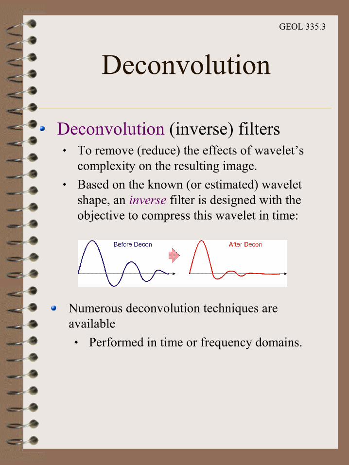
Deconvolution (inverse) filters To remove (reduce) the effects of wavelet’s
complexity on the resulting image. Based on the known (or estimated) wavelet
shape, an inverse filter is designed with the objective to compress this wavelet in time:
Numerous deconvolution techniques are available
Performed in time or frequency domains.
GEOL 335.3
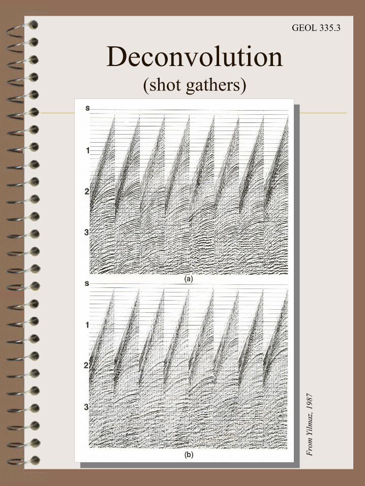
Deconvolution(shot gathers)
From
Yilm
az, 1
987

GEOL 335.3
Deconvolution(stack)
From Yilmaz, 1987
Interpreters certainly prefer working with the crisper, high-resolution image (b) that uses deconvolution.

GEOL 335.3
Signal/Noise Ratio enhancement by filtering
This is an example of the most common multichannel filter.Records are summed ('stacked') in order to increase the S/N ratio:
Signal is assumed the same in all channels, therefore, its amplitude is increased ∝N (the number of records);For incoherent noise, the energy becomes proportional to N, and so the amplitude increases as ;
Therefore, the S/N ratio ∝ .Note: coherent noise cannot be suppressed by stacking!
N
N
From Reynolds, 1997