Convincing worldwide: HERMETIC pumps in the refrigeration ...
24
CHEMICAL PETROCHEMICAL REFRIGERATION ENGERGY SERVICE Convincing worldwide: HERMETIC pumps in the refrigeration industry
Transcript of Convincing worldwide: HERMETIC pumps in the refrigeration ...

C H E M I C A L
P E T R O C H E M I C A L
R E F R I G E R A T I O N
E N G E R G Y
S E R V I C E
Convincing worldwide:
HERMETIC pumps
in the refrigeration industry

2 H E R M E T I C
Attitudes towards environmental awareness as well as social
responsibility have steadily grown in the refrigeration industry.
As an essential feature refrigeration plants must operate in a
hermetically sealed way and thus, the importance of tightness
has become more and more important for engineering, ecological
and economical reasons. Therefore , both safety in plants as well
as environmental protection play an important role in business
strategy. Not only ice-cream and frozen foods need to be cooled,
but almost every food. Typical application ranges include rail
vehicles, toboggan-runs, bob runs, breweries, etc. in which
HERMETIC pumps have been successfully used for reliable cooling
of plants and production processes. HERMETIC has been dedicated
to the development and production of hermetically sealed pumps
for a period of 50 years. HERMETIC pumps are designed for
applications in the chemical and petrochemical industry, as
well as for process technologies. The refrigeration industry also
benefi ts from this experience made in these industries. There
are more than 70.000 HERMETIC pumps installed in refrigeration
plants worldwide.
R E S P O N S I B I L I T Y
F O R T H E
E N V I R O N M E N T

H E R M E T I C 3
HERMETIC – synonym for hermetically
sealed pumps and reliability
The fi gure shows the simplifi ed
scheme of a large refrigeration plant.
The characteristic of this plant is that
the refrigerant fl ows through a central
fl uid separator and is then conveyed
to the evaporators. The resulting
vapour and the surplus fl uid return
Compressor
Flow control valve
Cooling water Condenser Separator
Qmin
-Orifi ce
Qmax
-Orifi ce or constant fl ow regulator
Evaporator
HERMETIC pump
back to the separator. Compressor,
condenser and fl ow control are
incorporated in a secondary circuit.
Hermetically sealed pumps ensure
a safe and controlled conveying of
refrigerants. Besides absolute tightness
HERMETIC refrigeration pumps feature
the following:■ long service life■ low operating costs■ rapid and reduced acquisition and
stockkeeping of spare parts

4 H E R M E T I C
S I N G L E - S T A G E
C A N N E D
M O T O R P U M P S
General
HERMETIC pumps are completely
self-contained centrifugal pumps
without any shaft sealing, driven
electro-magnetically by the canned
motor. The CNF model has been spe-
cially developed for pumping liquifi ed
petroleum gas. This single-stage pump
design now allows for the pumping
of liquifi ed petroleum gases with
an extremely steep vapour pressure
diagram. There is no need for external
recirculation of the partial fl ow into
the suction vessel and the separator.
Design
The pumps use a single-stage impeller
mounted directly on an integral induc-
tion motor. The pump volute casings
and impellers are derived from the
standard chemical pumps as defi ned
by EN 22858; ISO 2858.
Operating range
Capacity Q: max. 50 m3/h
Head H: max. 57 m.c.l.
Application sector
Liquid gases as e.g. R 717 (NH3),
R 22 (Frigen), CO2, R 134a, R 404a,
R11, R12, baysilone (M3, M5),
methanol, silicon oil KT3, syltherm,
lithium bromide.
In principle the refrigeration pumps
are suitable for use with all refrigerant
liquids. Please consult for any fl uids
not listed above.
H E R M E T I C 5
P U M P S E R I E S C N F
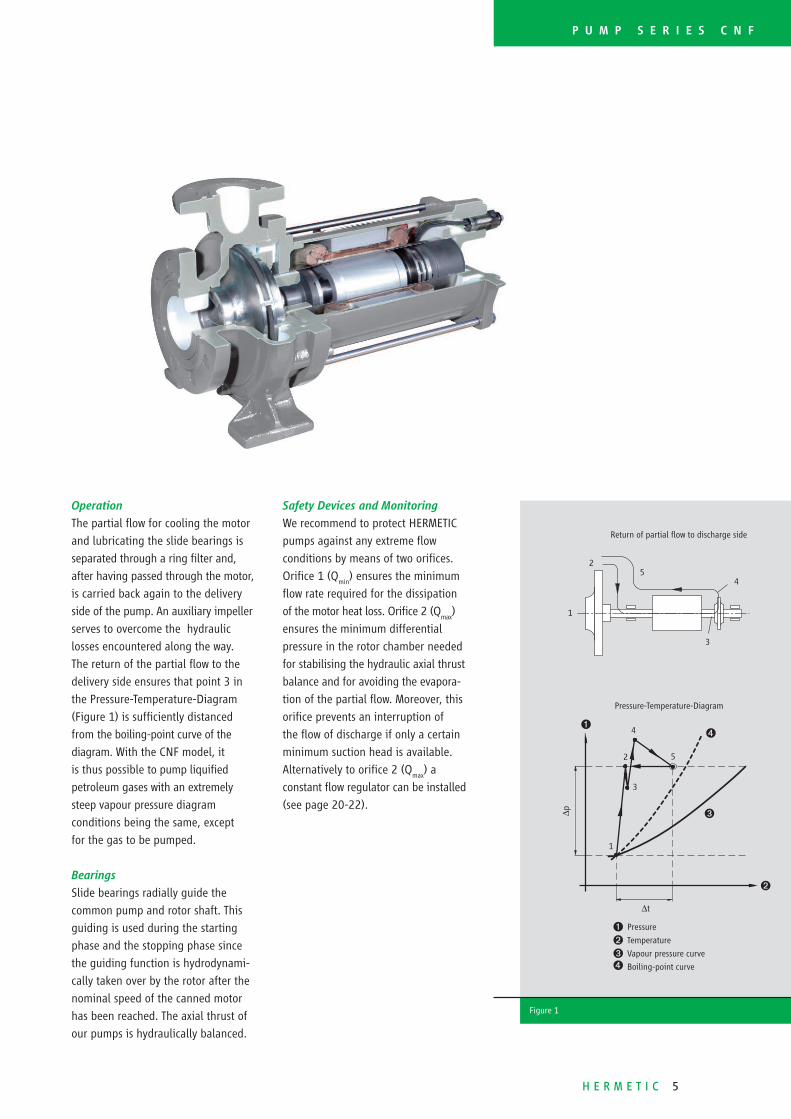
Pressure-Temperature-Diagram
4
2 5
3
1
∆t
∆p
Ê
Ì
Ë
Ê Pressure
Ë Temperature
Ì Vapour pressure curve
Í Boiling-point curve
Return of partial fl ow to discharge side
1
2
4
3
5
Figure 1
▲
Operation
The partial fl ow for cooling the motor
and lubricating the slide bearings is
separated through a ring fi lter and,
after having passed through the motor,
is carried back again to the delivery
side of the pump. An auxiliary impeller
serves to overcome the hydraulic
losses encountered along the way.
The return of the partial fl ow to the
delivery side ensures that point 3 in
the Pressure-Temperature-Diagram
(Figure 1) is suffi ciently distanced
from the boiling-point curve of the
diagram. With the CNF model, it
is thus possible to pump liquifi ed
petroleum gases with an extremely
steep vapour pressure diagram
conditions being the same, except
for the gas to be pumped.
Bearings
Slide bearings radially guide the
common pump and rotor shaft. This
guiding is used during the starting
phase and the stopping phase since
the guiding function is hydrodynami-
cally taken over by the rotor after the
nominal speed of the canned motor
has been reached. The axial thrust of
our pumps is hydraulically balanced.
Safety Devices and Monitoring
We recommend to protect HERMETIC
pumps against any extreme fl ow
conditions by means of two orifi ces.
Orifi ce 1 (Qmin
) ensures the minimum
fl ow rate required for the dissipation
of the motor heat loss. Orifi ce 2 (Qmax
)
ensures the minimum differential
pressure in the rotor chamber needed
for stabilising the hydraulic axial thrust
balance and for avoiding the evapora-
tion of the partial fl ow. Moreover, this
orifi ce prevents an interruption of
the fl ow of discharge if only a certain
minimum suction head is available.
Alternatively to orifi ce 2 (Qmax
) a
constant fl ow regulator can be installed
(see page 20-22).
Í

6 H E R M E T I C
Impeller 169 - 130 mm Ø, Width 9 mm Impeller 209-160 mm Ø, Width 7 mm
Impeller 169-130 mm Ø, Width 15 mm Impeller 209-160 mm Ø, Width 12 mm
0 5 10 15 20 25 30 35 40
Performance Curve 2800 rpm
Q max-Orifice Ø 22
Q min-Orifice Ø 10
Ø 169
2030
4045
50
55
η %
50
45
40
Ø 150
Ø 150
Ø 130
Ø 169
Ø 169
Inducer
Ø 130
Ø 130
Q [m3/h]
45
40
35
30
25
20
15
10
5
0
8
6
4
2
0
5
4
3
2
1
0
P[kW]
NPSH [m]
H[m]
0 5 10 15 25 30 35 40
0 5 10 15 20 25 30 35 40
Performance Curve 2800 rpm
Q max-Orifice Ø 20
Q min-Orifice Ø 10
Ø 209 2030
4045
50
52
η %
50
45
40
Ø 200
Ø 200
Ø 160
Ø 209
Ø 209
Inducer
Ø 160
Ø 180
Q [m3/h]
70
60
50
40
30
20
10
0
5
0
8
6
4
2
0
P[kW]
NPSH [m]
H[m]
0 5 10 15 30 35 40
Ø 180
Q max-Orifice Ø 21
Q max-Orifice Ø 22
Ø 160
0 10 20 30 40 50 60 70 80 90 100
Performance Curve 2800 rpm
Q max-Orifice Ø 30
Q min-Orifice Ø 11
Ø 169
20 3040
5055
60
η %Ø 150
Ø 150
Ø 130
Ø 169
Ø 169
Inducer
Ø 130
Ø 130
Q [m3/h]
45
40
35
30
25
20
15
10
5
0
4
3
2
1
0
10
8
6
4
2
0
P[kW]
NPSH [m]
H[m]
0 10 20 30 40 60 70 80 90 100
62
65
62
60
50
55 Q max-Orifice Ø 31
Q max-Orifice Ø 33
0 10 20 30 40 50 60 70 80 90 100
Performance Curve 2800 rpm
Q max-Orifice Ø 27
Q min-Orifice Ø 11
20 30 4050
5560
η %
Ø 180
Ø 180
Ø 160
Ø 209
Ø 209
Inducer
Ø 160
Ø 160
Q [m3/h]
65
60
55
50
45
40
35
30
25
20
15
10
5
0
4
3
2
1
0
15
10
5
0
P[kW]
NPSH [m]
H[m]
0 10 20 30 40 60 70 80 90 100
62
60
55
Q max-Orifice Ø 29
Q max-Orifice Ø 31
Ø 209
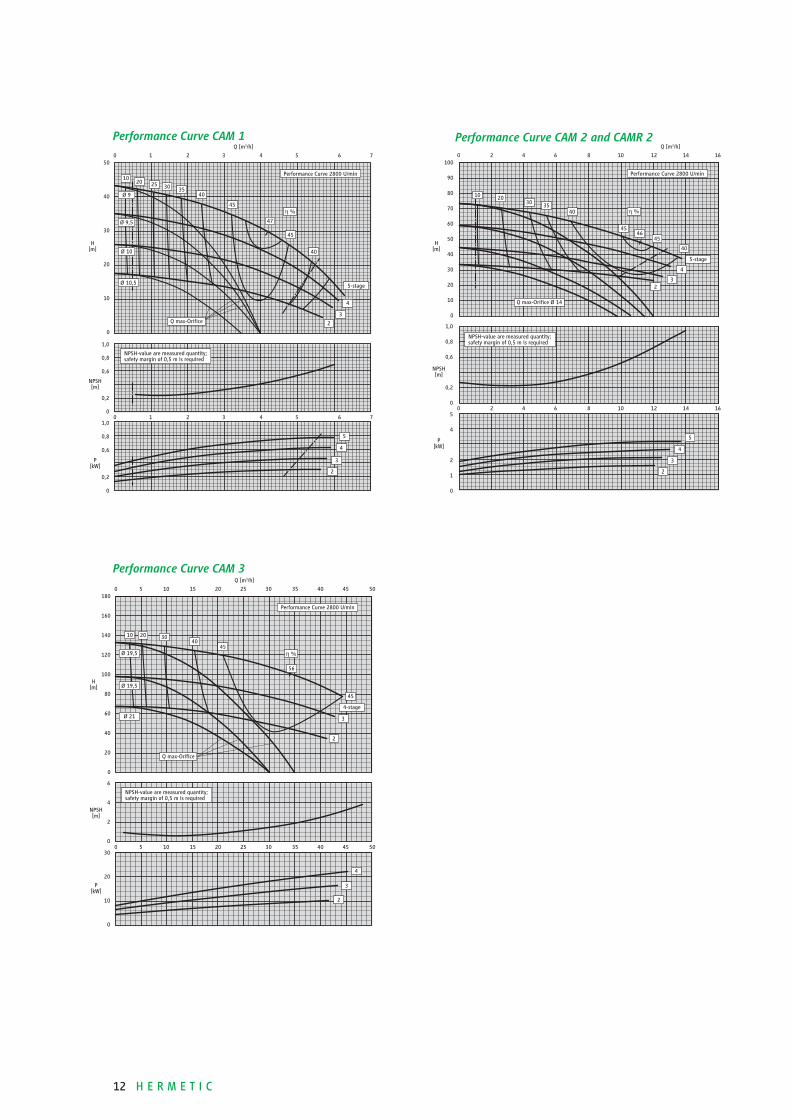
NPSH-value are measured quantity; safety margin of 0,5 m is required
NPSH-value are measured quantity; safety margin of 0,5 m is required
NPSH-value are measured quantity; safety margin of 0,5 m is required
NPSH-value are measured quantity; safety margin of 0,5 m is required
Performance Curve CNF 40 - 200
Performance Curve CNF 50 - 160
Performance Curve CNF 40 - 160
Performance Curve CNF 50 - 200
H E R M E T I C 7
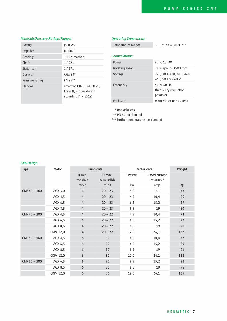
CNF- Design
Type Motor Pump data Motor data Weight
Q min.
required
m3 / h
Q max.
permissible
m3 / h
Power
kW
Rated current
at 400 V /
Amp. kg
CNF 40 – 160 AGX 3,0 4 20 – 23 3,0 7,1 58
AGX 4,5 4 20 – 23 4,5 10,4 66
AGX 6,5 4 20 – 23 6,5 15,2 69
AGX 8,5 4 20 – 23 8,5 19 80
CNF 40 – 200 AGX 4,5 4 20 – 22 4,5 10,4 74
AGX 6,5 4 20 – 22 6,5 15,2 77
AGX 8,5 4 20 – 22 8,5 19 90
CKPx 12,0 4 20 – 22 12,0 26,1 122
CNF 50 – 160 AGX 4,5 6 50 4,5 10,4 77
AGX 6,5 6 50 6,5 15,2 80
AGX 8,5 6 50 8,5 19 91
CKPx 12,0 6 50 12,0 26,1 118
CNF 50 – 200 AGX 6,5 6 50 6,5 15,2 82
AGX 8,5 6 50 8,5 19 96
CKPx 12,0 6 50 12,0 26,1 125
Materials/Pressure Ratings/Flanges
Casing JS 1025
Impeller JL 1040
Bearings 1.4021/ carbon
Shaft 1.4021
Stator can 1.4571
Gaskets AFM 34*
Pressure rating PN 25**
Flanges according DIN 2534, PN 25,
Form N, groove design
according DIN 2512
P U M P S E R I E S C N F
Operating Temperature
Temperature rangea – 50 °C to + 30 °C ***
Canned Motors
Power up to 12 kW
Rotating speed 2800 rpm or 3500 rpm
Voltage 220, 380, 400, 415, 440,
460, 500 or 660 V
Frequency 50 or 60 Hz
(frequency regulation
possible)
Enclosure Motor/Rotor IP 64 / IP67
* non asbestos
** PN 40 on demand
*** further temperatures on demand

8 H E R M E T I C
List of parts CNF
102 volute casing
230.1 impeller
513 wear ring insert
529.1 bearing sleeve
811 motor casing
816 stator can
819 rotor shaft
400.4 gasket
160 cover
545.2 bearing bush
529.2 bearing sleeve
502 wear ring
758 fi lter
400.5 gasket
812.1 motor casing cover
381 bearing insert
813 stator core
230.3 auxiliary impeller
411.10 joint ring
400.6 gasket
400.3 gasket
545.1 bearing bush
525.1 distance sleeve
821 rotor core

H E R M E T I C 9
P U M P S E R I E S C N F
CNF-Design
Dimension CNF
40 – 160
CNF
40 – 160
CNF
40 – 200
CNF
40 – 200
CNF
50 – 160
CNF
50 – 160
CNF
50 – 200
CNF
50 – 200
AGX
3,0 to 6,5
AGX
8,5
AGX
4,5/6,5
AGX
8,5/12,0
AGX
4,5/6,5
AGX
8,5/12,0
AGX
6,5
AGX
8,5/12,0
Length/L 506 575 526 595/620 526 595/620 526 595/620
Width/W 240 240 265 265/290 265 265/290 265 265/290
Height/H 292 292 340 340 340 340 360 360
h1 132 132 160 160 160 160 160 160
h2 160 160 180 180 180 180 200 200
b 80 80 100 100 100 100 100 100
v 100 100 115 115 108 108 118 118
DNS
65 65 65 65 80 80 80 80
DND
40 40 40 40 50 50 50 50
Ê Cable U1, V1, W1 + protective conductor y 4 x 1,5 mm2, Cable for winding protection2 x 1,5 mm2, cable number 5 + 6, cable length 2,5 m
Ë Pressure gauge G 1/4
L
DNS
DND
b
Ê
Ë
h1
h2
W
V
H
L
DNS
DND
b
Ê
Ì
Ë
Í
V h1
h2
W
V
H
Ê Cable U1, V1, W1 + protective conductor y
4 x 4 mm2, cable length 2,5 m
Ë Cable for winding protection2 x 0,75 mm2, cable number 5 + 6, cable length 2,5 m
Ì Pressure gaugeG 1/4
Í Adaptor for connection of temperature monitorclosed with plug DIN 910, G 1/2
Dimensional drawing for motor type:
AGX 3,0 / AGX 4,5 / AGX 6,5
Dimensional drawing for motor type:
AGX 8,5 / CKPx 12,0

10 H E R M E T I C
General
The CAM und CAMR range of HERMETIC
pumps are completely closed. They
operate using the canned motor principle
which removes the need for any shaft
seal. The CAM and CAMR ranges have
been developed especially for the
refrigeration applications, their
features include:■ Low NPSH values■ Pump built in two to fi ve stages
to suit the application■ Able to pump 14 m3/h with a
suction head of only 1,0 m■ Suitable for pumping ammonia,
freons and other refrigerants■ The machines were examined by
several classifi cation companies and
also have approval for use on ships
The CAMR range is a special version of
the CAM 2 range designed for compact
plants with small collecting vessels.
The design enables:■ Space saving by mounting the
pump directly under the vessel■ Escaping of gas through the
suction port, allowing shorter
re-starting times■ The hydraulic data and NPSH
value are identical to the CAM 2
Design
The pumps use multistage impeller
mounted directly on an integral
induction motor.
Operating range
Capacity Q: max. 35 m3/h
Head H: max. 130 m.c.l.
Application sector
Liquid gases as e.g. R 717 (NH3),
R 22 (Frigen), CO2, R 134a, R 404a,
R 11, R 12, baysilone (M3, M5),
methanol, silicon oil KT3, syltherm,
lithium bromide.
In principle the refrigeration pumps
are suitable for use with all refrigerant
liquids. Please consult for any fl uids
not listed above.
M U L T I S T A G E
C A N N E D
M O T O R P U M P S
H E R M E T I C 11
P U M P S E R I E S C A M
Pressure-Temperature-Diagram
4
2
5
31
∆t
∆p
Ê
Ì
Ë
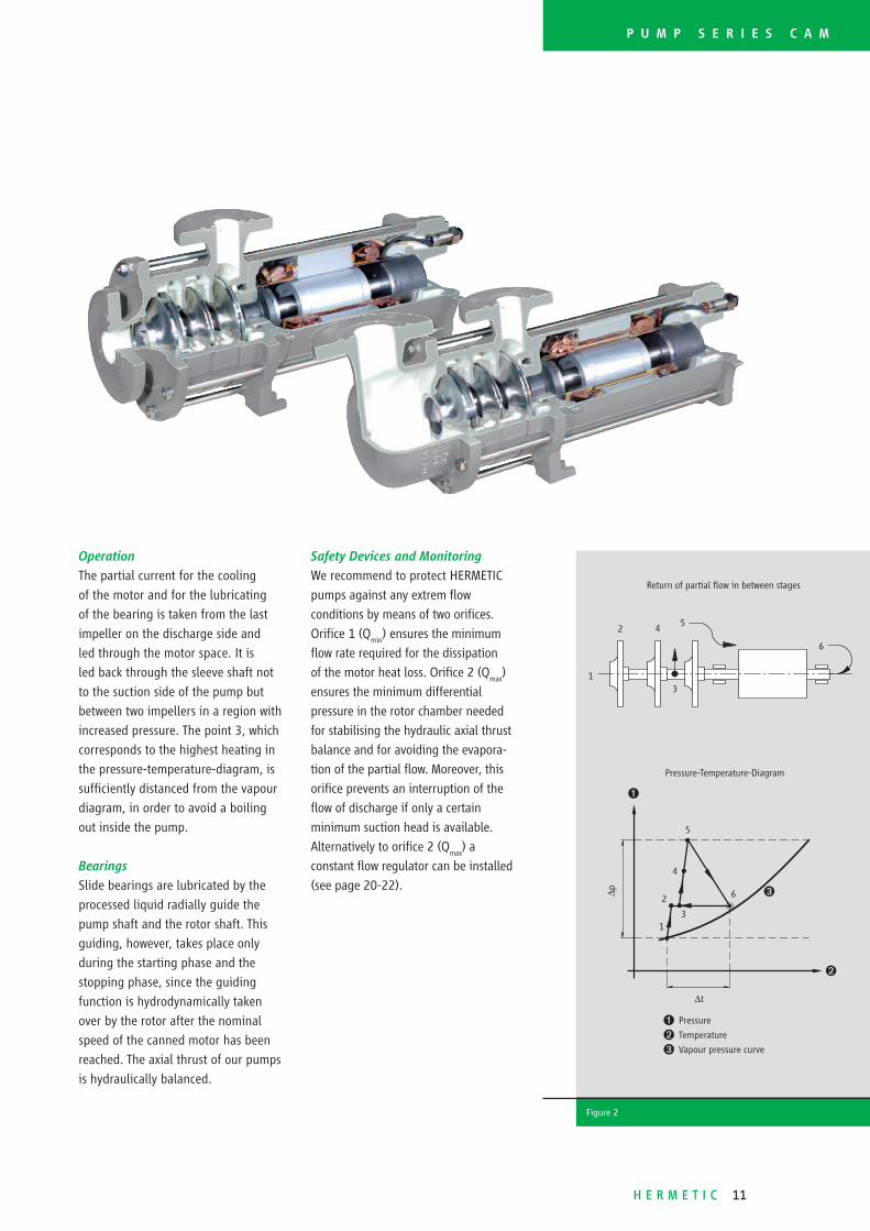
Ê Pressure
Ë Temperature
Ì Vapour pressure curve
6
Return of partial fl ow in between stages
1
2 4
3
5
Figure 2
6
▲
Operation
The partial current for the cooling
of the motor and for the lubricating
of the bearing is taken from the last
impeller on the discharge side and
led through the motor space. It is
led back through the sleeve shaft not
to the suction side of the pump but
between two impellers in a region with
increased pressure. The point 3, which
corresponds to the highest heating in
the pressure-temperature-diagram, is
suffi ciently distanced from the vapour
diagram, in order to avoid a boiling
out inside the pump.
Bearings
Slide bearings are lubricated by the
processed liquid radially guide the
pump shaft and the rotor shaft. This
guiding, however, takes place only
during the starting phase and the
stopping phase, since the guiding
function is hydrodynamically taken
over by the rotor after the nominal
speed of the canned motor has been
reached. The axial thrust of our pumps
is hydraulically balanced.
Safety Devices and Monitoring
We recommend to protect HERMETIC
pumps against any extrem fl ow
conditions by means of two orifi ces.
Orifi ce 1 (Qmin
) ensures the minimum
fl ow rate required for the dissipation
of the motor heat loss. Orifi ce 2 (Qmax
)
ensures the minimum differential
pressure in the rotor chamber needed
for stabilising the hydraulic axial thrust
balance and for avoiding the evapora-
tion of the partial fl ow. Moreover, this
orifi ce prevents an interruption of the
fl ow of discharge if only a certain
minimum suction head is available.
Alternatively to orifi ce 2 (Qmax
) a
constant fl ow regulator can be installed
(see page 20-22).
12 H E R M E T I C
Performance Curve CAM 2 and CAMR 2
0 2 4 6 8 10 12 14 16
Performance Curve 2800 U/min
5-stage
Q max-Orifice Ø 14
2030
3540 η %
40
2
Q [m3/h]
100
90
80
70
60
50
40
30
20
10
0
1,0
0,8
0,6
0,2
0
5
4
2
1
0
P[kW]
NPSH [m]
H[m]
NPSH-value are measured quantity;safety margin of 0,5 m is required
10
4645
3
4
2
3
4
5
45
0 2 4 6 8 10 12 14 16
0 5 10 15 20 25 30 35 40 45 50
Performance Curve 2800 U/min
4-stage
Q max-Orifice
20 3040
45η %
45
2
Ø 19,5
Q [m3/h]
180
160
140
120
100
80
60
40
20
0
6
4
2
0
30
20
10
0
P[kW]
NPSH [m]
H[m]
NPSH-value are measured quantity;safety margin of 0,5 m is required
Ø 21
10
56
3
2
3
4
0 5 10 15 20 25 30 35 40 45 50
Ø 19,5
Performance Curve CAM 3
0 1 2 3 4 5 6 7
Performance Curve 2800 U/min
5-stage
Q max-Orifice
Ø 9
2030
3540
45η %
40
2
Ø 9,5
Ø 10
Q [m3/h]
50
40
30
20
10
0
1,0
0,8
0,6
0,2
0
1,0
0,8
0,6
0,2
0
P[kW]
NPSH [m]
H[m]
NPSH-value are measured quantity;safety margin of 0,5 m is required
Ø 10,5
1025
47
45
3
4
2
3
4
0 1 2 3 4 5 6 7
5
Performance Curve CAM 1

H E R M E T I C 13
CAM / CAMR- Design
Type Motor Pump data Motor data Weight
Q min.
required
m3 / h
Q max.
permissible
m3 / h
Power
kW
Rated current
at 400 V /
Amp. kg
CAM 1/2 AGX 1,0 0,5 3,5 1,0 2,7 27
CAM 1/3 AGX 1,0 0,5 4 1,0 2,7 28
CAM 1/4 AGX 1,0 0,5 4 1,0 2,7 29
CAM 1/5 AGX 1,0 0,5 4 1,0 2,7 30
CAM (R) 2/2 AGX 3,0 1 10 3,0 7,1 48
CAM (R) 2/3 AGX 3,0 1 10,5 3,0 7,1 52
CAM (R) 2/3 AGX 4,5 1 10,5 4,5 10,4 60
CAM (R) 2/4 AGX 3,0 1 11,5 3,0 7,1 56
CAM (R) 2/4 AGX 4,5 1 11,5 4,5 10,4 68
CAM (R) 2/5 AGX 3,0 1 12,5 3,0 7,1 60
CAM (R) 2/5 AGX 4,5 1 12,5 4,5 10,4 74
CAM (R) 2/5 AGX 6,5 1 12,5 6,5 15,2 77
CAM 3/2 AGX 8,5 6 30 8,5 19 120
CAM 3/2 CKPx 12,0 6 30 12,0 26,1 150
CAM 3/2 CKPx 19,0 6 30 19,0 38 195
CAM 3/3 AGX 8,5 6 30 8,5 19 138
CAM 3/3 CKPx 12,0 6 30 12,0 26,1 168
CAM 3/3 CKPx 19,0 6 30 19,0 38 213
CAM 3/4 CKPx 12,0 6 35 12,0 26,1 186
CAM 3/4 CKPx 19,0 6 35 19,0 38 231
P U M P S E R I E S C A M / C A M R
Materials/Pressure Ratings/Flanges
Casing JS 1025
Suction cover
(Suction casting CAMR 2)
JS 1025
Stage casing
(CAM 1, CAM 2, CAMR 2)
1.0460
Stage casing (CAM 3) JS 1025
Diffuser insert
(Diffuser CAM 3)
JL 1030
Impellers JL 1030
Bearings 1.4021/ carbon
Shaft 1.4021
Stator can 1.4571
Gaskets AFM 34*
Pressure rating PN 25**
Flanges according DIN 2534, PN 25,
Form N, groove design
according DIN 2512
Operating Temperature
Temperature range – 50 °C to + 30 °C ***
Canned Motors
Power up to 19 kW
Rotating speed 2800 rpm or 3500 rpm
Voltage 220, 380, 400, 415, 440,
460, 500 or 660 V
Frequency 50 or 60 Hz
(frequency regulation
possible)
Enclosure Motor/Rotor IP 64 / IP 67
* non asbestos
** PN 40 on demand
*** further temperatures on demand
14 H E R M E T I C
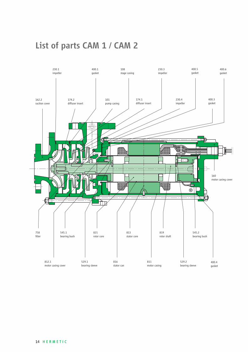
List of parts CAM 1 / CAM 2
162.2 suction cover
230.1 impeller
174.2 diffuser insert
400.1 gasket
101 pump casing
108 stage casing
174.1 diffuser insert
230.3 impeller
230.4 impeller
400.5 gasket
400.3 gasket
758 fi lter
545.1 bearing bush
821 rotor core
813 stator core
819 rotor shaft
545.2 bearing bush
529.1 bearing sleeve
816 stator can
811 motor casing
529.2 bearing sleeve
812.1 motor casing cover
160 motor casing cover
400.6 gasket
400.4 gasket

H E R M E T I C 15
CAM 1-Design
Dimension CAM
1/2-stage
CAM
1/3-stage
CAM
1/4-stage
CAM
1/5-stage
AGX
1,0
AGX
1,0
AGX
1,0
AGX
1,0
Length/L 419 447 475 503
Width/W 160 160 160 160
Height/H 210 210 210 210
h1 90 90 90 90
h2 120 120 120 120
i 112 140 168 196
DNS
25 25 25 25
DND
20 20 20 20
CAM 2-Design
Dimension CAM
2/2-stage
CAM
2/3-stage
CAM
2/4-stage
CAM
2/5-stage
AGX
3,0
AGX
3,0/4,5
AGX
3,0/4,5
AGX 3,0/
4,5/6,5
Length/L 536 577 618 659
Width/W 218 218 218 218
Height/H 250 250 250 250
h1 110 110 110 110
h2 140 140 140 140
i 135 176 217 258
DNS
40 40 40 40
DND
32 32 32 32
P U M P S E R I E S C A M 1 / C A M 2
Ê Cable U1, V1, W1 + protective conductor y
4 x 1,5 mm2, cable length 2,5 m
Ë Pressure gauge G 1/4
L
DNS
DND
i
Ê
h1
h2
W
H
Ë
Dimensional drawing for motor type: AGX 1,0 / AGX 3,0 / AGX 4,5 / AGX 6,5
16 H E R M E T I C
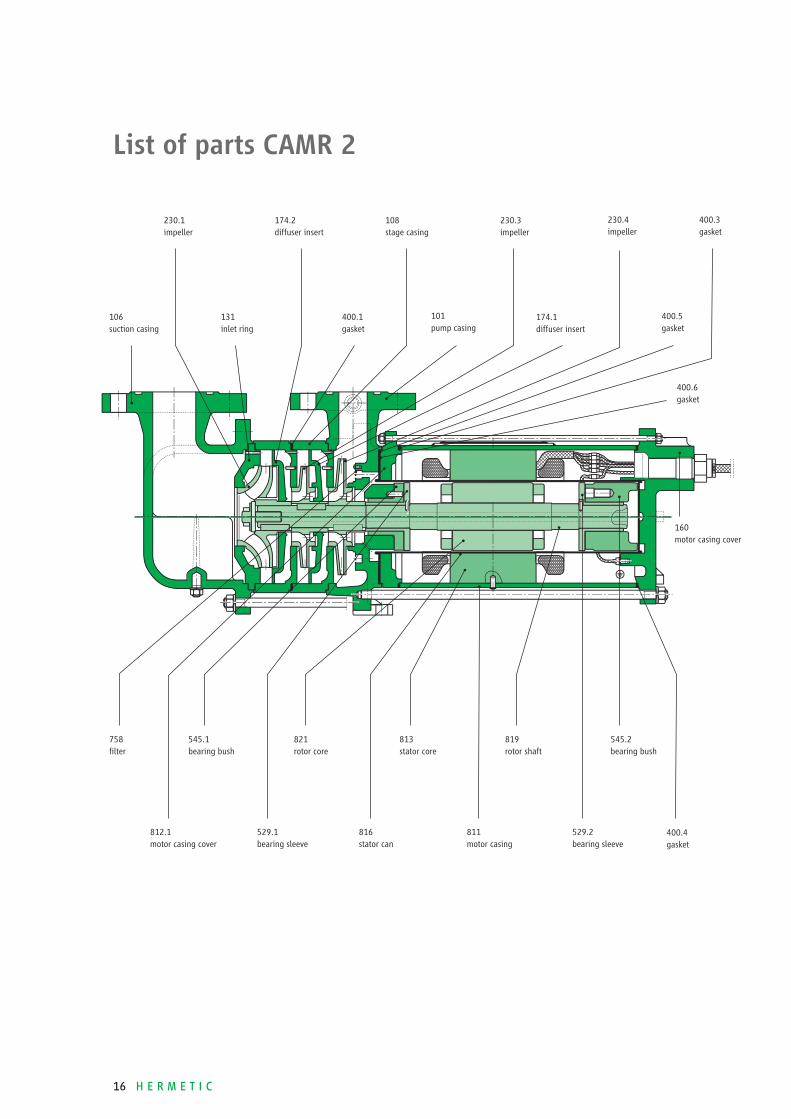
List of parts CAMR 2
106 suction casing
230.1 impeller
131 inlet ring
174.2 diffuser insert
400.1 gasket
108 stage casing
101 pump casing
230.3 impeller
174.1 diffuser insert
230.4 impeller
400.5 gasket
758 fi lter
545.1 bearing bush
821 rotor core
813 stator core
819 rotor shaft
545.2 bearing bush
529.1 bearing sleeve
816 stator can
811 motor casing
529.2 bearing sleeve
812.1 motor casing cover
160 motor casing cover
400.6 gasket
400.4 gasket
400.3 gasket
H E R M E T I C 17
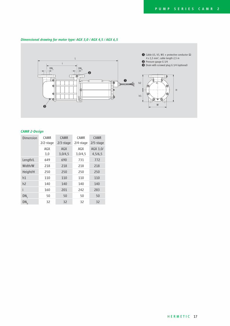
P U M P S E R I E S C A M R 2
CAMR 2-Design
Dimension CAMR
2/2- stage
CAMR
2/3- stage
CAMR
2/4- stage
CAMR
2/5- stage
AGX
3,0
AGX
3,0/4,5
AGX
3,0/4,5
AGX 3,0/
4,5/6,5
Length/L 649 690 731 772
Width/W 218 218 218 218
Height/H 250 250 250 250
h1 110 110 110 110
h2 140 140 140 140
i 160 201 242 283
DNS
50 50 50 50
DND
32 32 32 32
Ë
Dimensional drawing for motor type: AGX 3,0 / AGX 4,5 / AGX 6,5
L
DNS
DND
i
Ê
h1
h2
W
H
Ê Cable U1, V1, W1 + protective conductor y
4 x 1,5 mm2, cable length 2,5 m
Ë Pressure gauge G 1/4
Ì Drain with screwed plug G 1/4 (optional)
Ì
18 H E R M E T I C
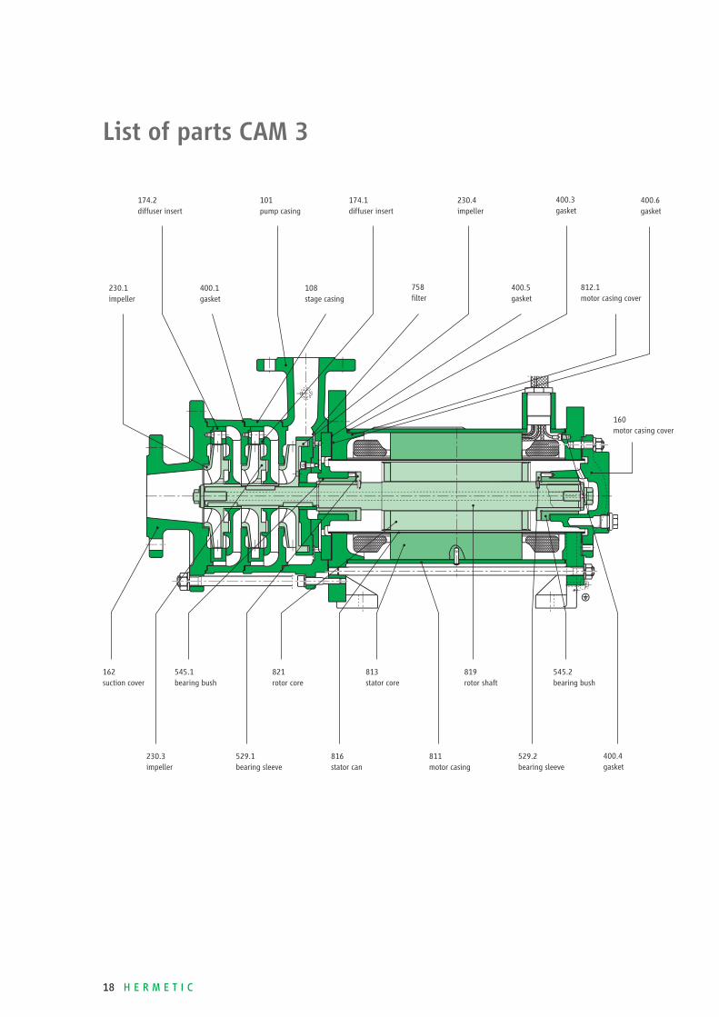
List of parts CAM 3
230.1 impeller
174.2 diffuser insert
400.1 gasket
101 pump casing
108 stage casing
174.1 diffuser insert
758 fi lter
230.4 impeller
400.5 gasket
400.3 gasket
812.1 motor casing cover
162 suction cover
545.1 bearing bush
821 rotor core
813 stator core
819 rotor shaft
545.2 bearing bush
529.1 bearing sleeve
816 stator can
811 motor casing
529.2 bearing sleeve
230.3 impeller
160 motor casing cover
400.6 gasket
400.4 gasket

H E R M E T I C 19
CAM 3-Design
Dimension CAM
3/2- stage
CAM
3/2- stage
CAM
3/2- stage
CAM
3/3- stage
CAM
3/3- stage
CAM
3/3- stage
CAM
3/4- stage
CAM
3/4- stage
AGX 8,5 CKPx 12,0 CKPx 19,0 AGX 8,5 CKPx 12,0 CKPx 19,0 CKPx 12,0 CKPx 19,0
Length/L 597 642 707 654 699 764 756 821
Width/W 250 290 340 250 290 340 290 340
Height/H 355 380 380 355 380 380 380 380
h1 145 170 170 145 170 170 170 170
h2 210 210 210 210 210 210 210 210
i 184 184 184 241 241 241 298 298
DNS
65 65 65 65 65 65 65 65
DND
40 40 40 40 40 40 40 40
P U M P S E R I E S C A M 3
¶ Cable U1, V1, W1 + protective conductor y , 4 x 4 mm2, cable length 2,5 m
Ë Cable for winding protection, 2 x 0,75 mm2, cable length 2,5 m
Ì Pressure gauge G 1/4
Dimensional drawing for motor type: AGX 8,5 / CKPx 12,0 / CKPx 19,0
Ë
L
DNS
DND
i
Ê
h1
h2
W
H
Ì

Operation
The constant fl ow regulator must
remain full of fl uid during system
operation. The operation of the valve
is dependent on the characteristics
of the fl owing media. It is therefore
important that when ordering a valve,
complete fl uid specifi cations are
included. Specifi c gravity is the most
important value for the correct design
of a valve.
Maintenance
There is no need for regular mainte-
nance of the constant fl ow regulator
and no readjustment is required.
Spare cartridge assemblies may be
ordered when required.
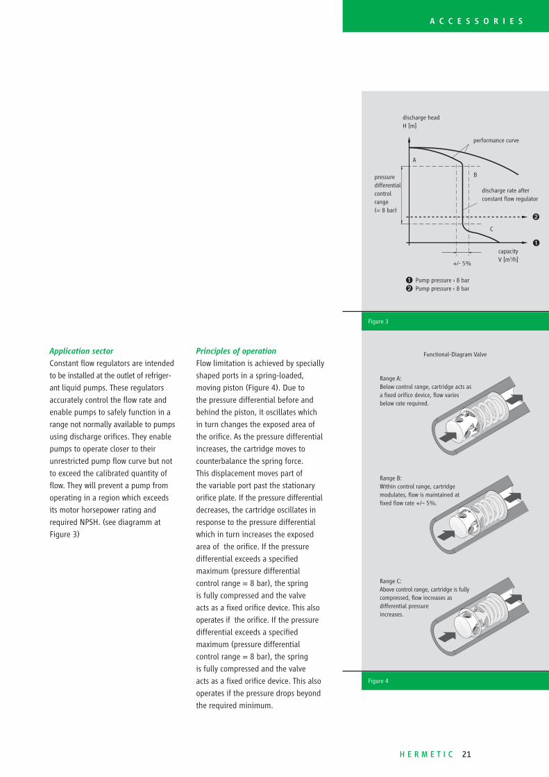
General
The constant fl ow regulator has been
developed especially for refrigeration
plants. These valves facilitate a safe
operation of pumps in a sphere, which
normally is impossible for pumps
with Qmax
-orifi ce. Figure 3 shows the
additional operational range which is
obtained by the application of a constant
fl ow regulator instead of a Qmax
-orifi ce.
Often a smaller pump, more economi-
cally priced, can be installed.
C O N S T A N T F L O W
R E G U L A T O R
20 H E R M E T I C
H E R M E T I C 21
A C C E S S O R I E S
Range A:Below control range, cartridge acts as a fi xed orifi ce device, fl ow varies below rate required.
Range B:Within control range, cartridge modulates, fl ow is maintained at fi xed fl ow rate +/– 5%.
Range C:Above control range, cartridge is fully compressed, fl ow increases as differential pressure increases.
Functional-Diagram Valve
Figure 4
Ê Pump pressure › 8 bar
Ë Pump pressure ‹ 8 bar
performance curve
discharge rate afterconstant fl ow regulator
capacityV [m3/h]
discharge headH [m]
pressuredifferentialcontrol range(= 8 bar)
+/- 5%
A
B
C
Ê
Ë
Figure 3
Application sector
Constant fl ow regulators are intended
to be installed at the outlet of refriger-
ant liquid pumps. These regulators
accurately control the fl ow rate and
enable pumps to safely function in a
range not normally available to pumps
using discharge orifi ces. They enable
pumps to operate closer to their
unrestricted pump fl ow curve but not
to exceed the calibrated quantity of
fl ow. They will prevent a pump from
operating in a region which exceeds
its motor horsepower rating and
required NPSH. (see diagramm at
Figure 3)
Principles of operation
Flow limitation is achieved by specially
shaped ports in a spring-loaded,
moving piston (Figure 4). Due to
the pressure differential before and
behind the piston, it oscillates which
in turn changes the exposed area of
the orifi ce. As the pressure differential
increases, the cartridge moves to
counterbalance the spring force.
This displacement moves part of
the variable port past the stationary
orifi ce plate. If the pressure differential
decreases, the cartridge oscillates in
response to the pressure differential
which in turn increases the exposed
area of the orifi ce. If the pressure
differential exceeds a specifi ed
maximum (pressure differential
control range = 8 bar), the spring
is fully compressed and the valve
acts as a fi xed orifi ce device. This also
operates if the orifi ce. If the pressure
differential exceeds a specifi ed
maximum (pressure differential
control range = 8 bar), the spring
is fully compressed and the valve
acts as a fi xed orifi ce device. This also
operates if the pressure drops beyond
the required minimum.
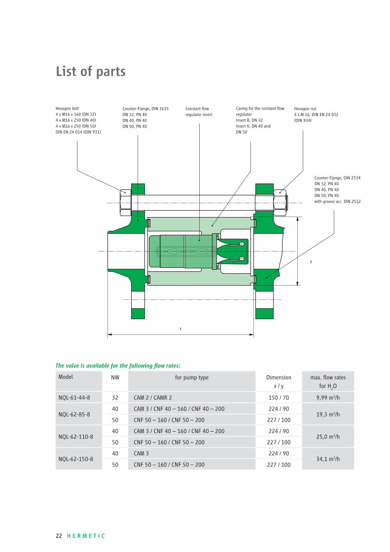
22 H E R M E T I C
The valve is available for the following fl ow rates:
Model NW for pump type Dimen sion
x / y
max. fl ow rates
for H2O
NQL-61-44-8 32 CAM 2 / CAMR 2 150 / 70 9,99 m3/h
NQL-62-85-840 CAM 3 / CNF 40 – 160 / CNF 40 – 200 224 / 90
19,3 m3/h50 CNF 50 – 160 / CNF 50 – 200 227 / 100
NQL-62-110-840 CAM 3 / CNF 40 – 160 / CNF 40 – 200 224 / 90
25,0 m3/h50 CNF 50 – 160 / CNF 50 – 200 227 / 100
NQL-62-150-840 CAM 3 224 / 90
34,1 m3/h50 CNF 50 – 160 / CNF 50 – 200 227 / 100
x
y
List of parts
Hexagon bolt4 x M16 x 160 (DN 32)4 x M16 x 250 (DN 40)4 x M16 x 250 (DN 50)DIN EN 24 014 (DIN 931)
Counter-Flange, DIN 2635DN 32, PN 40DN 40, PN 40DN 50, PN 40
Constant fl owregulator insert
Casing for the constant fl ow regulator Insert B, DN 32Insert K, DN 40 and DN 50
Counter-Flange, DIN 2534DN 32, PN 40DN 40, PN 40DN 50, PN 40 with groove acc. DIN 2512
Hexagon nut4 x M 16, DIN EN 24 032(DIN 934)

H E R M E T I C 23
A C C E S S O R I E S
Figure 5
Inducer
Inducers are axial impellers, which
are installed closely in front of the
fi rst impeller of a centrifugal pump
on the same shaft and which cause
an additional static pressure in front
of the impeller (Figure 5). They are
particularly used where the NPSHA is
not suffi cient in order to reduce the
NPSHR value of the pump. In many
cases inducers are also used preventi-
tively if the resistances of the suction
line cannot be determined exactly or
if the suction head is unpredictable,
or if there is a change of the overpres-
sure above the vapour pressure of
the liquid. Furthermore inducers are
particularly suitable for the transport
of liquids, which are affected with
disolved gases. In both cases the
inducer can serve to avoid cavitation
and minimum capacity.
Orifi ce Plates
It is possible to protect a HERMETIC
pump from extreme fl ow conditions by
installing 2 orifi ce plates. The Qmin
-
orifi ce guarantees the necessary fl ow
for the motor cooling and the bearing
lubrication. It also allows correct venting
of the pump at standstill. The Qmax
-
orifi ce ensures that the minimum
differential pressure is maintained
in the rotor space. This is necessary
for the stabilization of the hydraulic
axial thrust compensation and for
the avoidance of the partial current
vaporization. You can see the
installation of the orifi ces on page 3.

24 H E R M E T I C
HERMETIC-Pumpen GmbHGewerbestrasse 51 · D-79194 Gundelfi ngenphone +49-761-5830-0 · fax [email protected]://www.lederle-hermetic.com
Our products comply with:
■ Explosion protection acc. to
ATEX / UL / CQST / CSA■ VOC directive 1999/13/EC■ TA-Luft■ IPPC directive■ CE■ RCCM, level 2■ Rosgortechnazdor
HERMETIC-Pumpen GmbH
is certifi ed acc. to:
■ ISO 9001:2000■ GOST „R”■ ATEX 94/9/EG■ AD HP 0 / TRD 201■ AD WO / TRD 100■ DIN EN 729-2■ KTA 1401, QSP 4a
Convincing service.
Important features are readiness, mobility, fl exibility, availability and reliability.
We are anxious to ensure a pump operation at best availability and effi ciency
to our customers.
Installation and commissioning:
■ service effected on site by own
service technicians
Spare part servicing:
■ prompt and longstanding
availability■ customized assistance in spare
part stockkeeping
Repair and overhauling:
■ professional repairs including test
run executed by the parent factory■ or executed by one of our service
stations worldwide
Maintenance and service
agreement:
■ concepts individually worked
out to increase the availability
of your production facilities
Training and workshops:
■ extra qualifi cation of your
staff to ensure the course of
your manufacture
H-KÄLTE / E / 09 / 2006