Conveyor system stimulator - UC DRC Home
39
Conveyor System Simulator A thesis submitted to the Faculty of the Computer Engineering Technology Program of the University of Cincinnati in partial fulfillment of the requirements for the degree of Bachelor of Science In Computer Engineering Technology At the College of Engineering & Applied Science by JEFFERY M. SOULE II Bachelor of Science University of Cincinnati June 2011 Faculty Advisor: Dr. Xuefu Zhou
Transcript of Conveyor system stimulator - UC DRC Home

Conveyor System Simulator
A thesis submitted to the Faculty of the Computer Engineering Technology Program
of the University of Cincinnati in partial fulfillment of the
requirements for the degree of
Bachelor of Science
In Computer Engineering Technology At the College of Engineering & Applied Science
by
JEFFERY M. SOULE II
Bachelor of Science University of Cincinnati
June 2011
Faculty Advisor: Dr. Xuefu Zhou

8508 Arrowwood Dr Apt #101 Mason, OH 45040
June 7, 2011
Dr. Xuefu Zhou University of Cincinnati College of Engineering & Applied Science School of Electrical and Computing Systems 2220 Victory Parkway Cincinnati, OH 45206
Dear Dr Xuefu Zhou:
Attached is my final report on the "Conveyor System Simulator," requested by the esteemed faculty of the SECS department.
This final report explains, in as detail much detail as possible, the process that led to the completion of my project. In this report you will be presented with the problem, solution, and methodology associated with the project.
During this project I was not only assisted by you but also Herb Williams, Supervisor of Technology Services at Intelligrated and Andrew Kasako, Software Engineer at Intelligrated. I appreciate your time and effort in reading and reviewing this report and ask that if you have any questions or comments that you contact me.
Sincerely,
!llz-1--fr :TF Jeffery Soule II 504-214-7044 [email protected]

June 6, 2011
Jeffery Soule II Technical Support Engineering Co-Op
Conveyor System Simulator project
Dear Jeffery:
I would like to take this opportunity to recognize your exceptional completion of your workplace based senior design project. Your project using the new BOSS® interface gives us the ability to once again use the simulator for training and testing. This should prove to be a great addition to our new technical support research lab. This project also enhanced your knowledge of this software product line, the required programming, configuration and the ability to interface it with real world hardware to simulate an actual system. I am looking forward to working with you on future projects.
Herb Williams Supervisor, Technology Services
10045 Internat io nal Bou levard • Cincinnat i, OH 45246-4839 J. ,., lc; 513 .874.0788 • 513 .881.5144 • www.intelligrated .com

College of Engineering and Applied Science
Conveyor System Simulator
Jeffery Soule II
June 7, 2011
Submitted in partial fulfillment of the degree of
Bachelor of Science in
Computer Engineering Technology
Student Signature j J/ ~ ~ rtO ,~ Advisor Signature _ _______ ____ _

Conveyor System Simulator I page ll
ABSTRACT It takes approximately three months, in technical support, to get an engineer new to industrial automation and conveyors trained up to a point where they are able to answer the phone and effectively begin troubleshooting. There is an additional three months to get them accustomed to hearing a customer describe a problem, seeing an issue on the interface, and putting that information together to understand what is really happening on the system. Furthermore once the engineer is train to a proficient level he is then usually required to do coding for customers that run production daily and cannot afford any additional downtime as a result of untested code. This conveyor simulator first introduces a new engineer to the hardware and software he/she will be troubleshooting and supporting in Technical Support with part one of the project. Part two takes things one step further and allows the engineer to test code in a test environment that allows code to be tested with virtual inputs and outputs.

Conveyor System Simulator I page 12
INTRODUCTION This report outlines the seven month process of conceiving, restoring, designing, and completing the Conveyor System Simulator.
The Conveyor System Simulator is a two phase project. Phase one was re-controlling a test panel originally developed in the mid 1990's with our no longer supported BOSS 1 system. The control system was housed in the gold plated panel and ran PLM86 software. The original system can be seen below in Figure 1.
Figure 1: Original Training Station
The system in Figure 1 consisted of control relays, pilot lights, beacon lights, warning horns, and various styles of photo eyes. The wiring schematics for the system can be found in Appendices of this report.
Phase two of the project takes all the hardware seen here and virtually initializes it to simulate it is running when in fact nothing is connected to the system.
Conveyor System Simulator I page 13
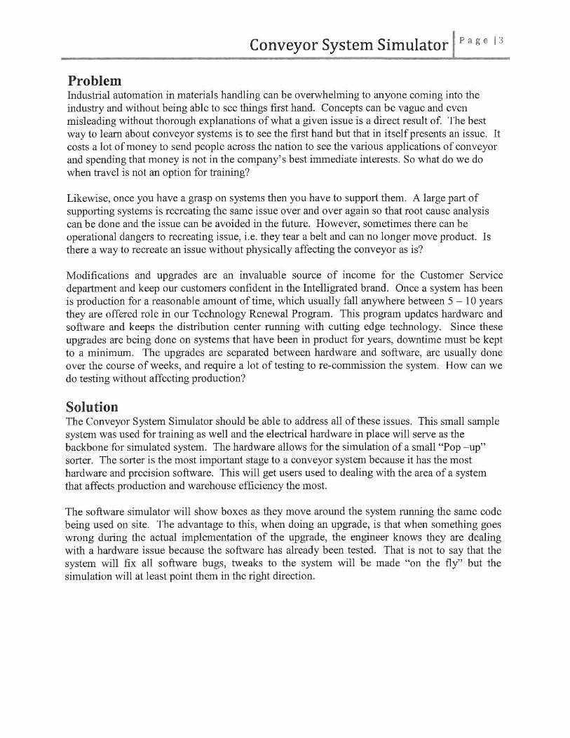
Problem Industrial automation in materials handling can be overwhelming to anyone coming into the industry and without being able to see things first hand. Concepts can be vague and even misleading without thorough explanations of what a given issue is a direct result of. The best way to learn about conveyor systems is to see the first hand but that in itself presents an issue. It costs a lot of money to send people across the nation to see the various applications of conveyor and spending that money is not in the company's best immediate interests. So what do we do when travel is not an option for training?
Likewise, once you have a grasp on systems then you have to support them. A large part of supporting systems is recreating the same issue over and over again so that root cause analysis can be done and the issue can be avoided in the future. However, sometimes there can be operational dangers to recreating issue, i.e. they tear a belt and can no longer move product. Is there a way to recreate an issue without physically affecting the conveyor as is?
Modifications and upgrades are an invaluable source of income for the Customer Service department and keep our customers confident in the Intelligrated brand. Once a system has been is production for a reasonable amount of time, which usually fall anywhere between 5 - 10 years they are offered role in our Technology Renewal Program. This program updates hardware and software and keeps the distribution center running with cutting edge technology. Since these upgrades are being done on systems that have been in product for years, downtime must be kept to a minimum. The upgrades are separated between hardware and software, are usually done over the course of weeks, and require a lot of testing to re-commission the system. How can we do testing without affecting production?
Solution The Conveyor System Simulator should be able to address all of these issues. This small sample system was used for training as well and the electrical hardware in place will serve as the backbone for simulated system. The hardware allows for the simulation of a small "Pop - up" sorter. The sorter is the most important stage to a conveyor system because it has the most hardware and precision software. This will get users used to dealing with the area of a system that affects production and warehouse efficiency the most.
The software simulator will show boxes as they move around the system running the same code being used on site. The advantage to this, when doing an upgrade, is that when something goes wrong during the actual implementation of the upgrade, the engineer knows they are dealing with a hardware issue because the software has already been tested. That is not to say that the system will fix all software bugs, tweaks to the system will be made "on the fly" but the simulation will at least point them in the right direction.

Conveyor System Simulator I page 14
"rW.DC't:).SrQP"TYP.
I
~ I.
!i
r ~ I
I I' '
I
® € ® o ~~"' 111.2CJC """"' bL~ l'llllrY-· .-' PCIDt
Figure 2: Representation of the Training System
Figure 2 is a representation of the system that is being controlled by the hardware in Figure I. It is used for speed and distance representations and calculations. Although there is no physical conveyor the system in place gives the engineer something to reference when he/she is doing troubleshooting the system.
Credibility The knowledge gained over the nearly four years of working at Intelligrated and the years spent in college have provided monumental assistance in this project.
Jeffery Soule Jeff has spent the majority of his life in the material handling industry, learning the Operations side of the business from his father, who managed UPS distribution centers, as a child. As an adult, he has worked as a Technical Support Engineering Co-Op at Intelligrated Systems for all of his Co-Op terms. In school, classes in AC/DC systems, C, C++, C#, Java, and Programmable Logic Controls (PLCs) all assisted in furthering his technical knowledge. Traveling all over the country for Intelligrated has allowed Jeff to see various applications of conveyor systems and seeing his peers sometime struggle in various areas provided the motivation for this project.
Goals and Methodology This project consists of two distinct parts, upgrading the software that is used to control the physical software then writing an engine that would allow for the I/0 points to be "faked out" or simulated by the software. Part one, once completed, developed a system for providing none "trial by fire" training for new Technical Support Engineers and provides a reference for any engineers that need re-familiarizing with the older hardware devices. Phase two allows for testing of new code before any change is physically made to the system. For instance, if Figure 2 were real and the customer wanted to add another after-sort lane, the software simulator would

Conveyor System Simulator I page I 5
allow for the addition of new hardware and controls to use the new lane before it were even installed.
. ;-; ........... , ..... , ...... .. "' · ~ ............ ···········: Jl 1111-· '1
.- -Server AC28 tardl RIO OPTO 22 board
Control station
Overview
Th~ server has two frard The contr~ $Vstem drives.. They can have (BOSS ) wiY use different OS's and bul => ... in15alllt> the ro throu~ ...... > only one can run al a
timl'. AC28 €:at d.
Figure 3: Block Diagram of How Part One Works
Rurr s{Stem normally Yes under norm11l SOSS 1-----< control.
Test System
The cootrol statioo will will afiG'.v us lo change fnte~ad ~llith Ole virtual system.
Stop eMl.irnlll tcmrmuniartions t(} the hard'I.'Oclrre.
Set the 'SimuJatiol'l Mode" bit (Input 0'11} ON.
lllse shll!red memory to flag the first !0 point to send a \irual trox
lllpdi'lte the tracking array to 'see' a box at the expected time instei'ld of 'looking• for on .
Figure 4: Block Diagram of How Pa11 Two Works
The remainder of this final report outlines in detail how the project was completed. This report includes sections on technical approach, budget, and problems encountered and future expansion.

Conveyor System Simulator I page 16
DICUSSION
Project Concept The Conveyor Simulator is the result of several different experiences and personal goals. The key concept behind the project was to help future engineers with the area of training where I felt the standards fell short. The secondary goal was to control a system from start to finish in a quest to get a deeper understanding of the code and its components. Initially, it was explained that there were several document available that would go step by step the deployment of a BOSS system but that documentation actually left out quite a bit of information. To compensate, the assistance of software engineers experienced in the areas where the most help was needed proved to be invaluable.
Initially there were plans for a 2D representation based on Figure 2. That would have actually shown boxes moving down the system and diverting down one of three lanes randomly but that idea was scrapped for two reasons. First, in Tech Support one cannot see the boxes moving down the system unless you are on site and that could lead to engineers being dependent on the 2D motion display instead of focusing on the hardware. The second reason was that the code necessary to create an accurate display would've been enough alone to qualify for a Senior Design project.
Design Objectives The objectives and design criteria for the Conveyor System Simulator are as foll ows:
BOSS3 Control System Since the Conveyor System Simulator is intended to train Technical Support Engineers it only made since to put the newest version of our control system on the sever controlling the hardware.
Maintaining scan times while in "Software Simulation" mode In the BOSS3 system there are multiple scan times where a certain portion of code must be executed repeatedly to keep track of the product on the line. Scan 1 must execute every 1 Oms and scan 4 must execute every 80ms. Maintaining these scan times while simulating the hardware was extremely important to purposes of simulating the software. For the purposes of this project scans 2 and 3 were not used.
Room for expansion The software is the only place that would be expanded and with the extensive work already done, it won't take too much more to change the programming.

Conveyor System Simulator I page 17
Technical Approach The technical approach taken during the hardware restoration, controlling, and testing of the Conveyor System Simulator was painstakingly meticulous. All system schematics are available in Appendices Band E. The C code used for this project is the proprietary property of Intelligrated Systems and will not be released in this report but a description of the method used to control and simulate the hardware will be provided in this section.
Server The Conveyor System Simulator is run on an Advantech server with the QNX6 operating system, which is a favorite Linux build of many Real Time Control systems in conveyors, smart flow pluming, and other material handling applications. The hardware used to interface to the hardware panel were two AC28 cards (one for inputs and one for outputs), a rocket port, and Ethernet adapters so that multiple sessions of the Human Machine Interface (HMI) could but open.
• QNX 6.0- QNX is a commercial Unix-like real-time operating system that basically operates the server the same way an embedded system controls a PIC. It is a highly adaptable OS based on the application it' s being used for.
• C (programming language)- A general-purpose computer programming language developed in the 70's at Bell Telephone Laboratories for use with the Unix operating system.
• GDB- The GNU Debugger is the standard debugger for the GNU software system. It works on many programming languages including Ada, C, C++, FreeBASIC, Free Pascal and even FORTRAN.
• JVM- The Java Virtual Machine allows the executing of Java byte-code which is what the HMI is compiled in.
Figure 5: The Conveyor System Simulator Server

Conveyor System Simulator I pa ge IS
Hardware Control • Prep Work - The first order ofbusiness was to spin up a virtual machine of a
QNX virtual environment and download a copy of the standard build of the BOSS3 code. The virtual system allowed for me to write the bulk of my code on my laptop. Appendix E shows the basic relay logic that was followed to while programming in C
• Server Populating - Once the software appeared to be ready to go onto the actual server for testing, a pax file was generated. Pax, portable archive exchange, is an archiving utility created by POSIX and defined by the POSIX.l-2001 standard. By default, it creates archives in the ustar format, also defined by the POSIX standard. Then QNX was loaded onto the real server. The pax file was then sent from the virtual machine to the server via FTP. Once the pax file was restored on the server, final configuring and 10 checkout could commence.
• Populating Screens - Java scripts are used to parse the files in C and populate screens for the HMI's of the s~~~fic~stem_:_ ____ ___ ______ _
I 1~1 o-er-DCM3021· 0 DCM3021-l
i ~ :::~ I 7 DCM3021-4 I 13 DCM3021·5 1 11 DCM3021·6 I 2 1 DCM3021·7 I 22 DCM3021-8
I ~~ g~::~o l 36 DCM302H1
37 DCM3021-l2 '12 DCM3022-D 43 OCM3022·1 44 OCM30Z2·Z 51 DCM3022·3 52 DCM3022·1 58 DCM3022·5 59 DCM3022·6 65 DCM3022-7 66 DCM3022·8 73 DCM3022·9 71 DCM3022·10 77 78 80 81 82 83 Bi 91 96 97 96 99
100
OCM3022·11 DCM3022-12 PE3021-l PE3021·2 PE3022-1 PE3022·2 PE3023 P:G022 LPB22601 PB2Z602 LPB20530 M1205 M3023
::::J I force ro ::::J ~ ~ gj ~ Jru 2::] J;.tl Stole Corbel OFF OfF OFF OFF OFF -OfF OFF -OFF
OFF OFF -OFF OFF OFF OFF OFF OFF OFF -OFF -OFF Off
SoLWCe Board Term W1re # fLEX C«d #1 02-02-oo 01 22302 A.EX Cord # 1 02-02-oo 02 22303 fLEX Cord # 1 02·02-oo 03 22304 A.EX Cord #1 02-02-00 06 22307 FLEX C..-d #1 02.02·00 07 22308 FLEXCard#1 02·02·00 13 22311 FLEX Cord #1 02·02·00 11 22315 FLEX Cord # 1 02-02·01 05 22322 FLEX Cord #1 02-02·01 06 22323 FLEX Cord #I 02-02-Dl 12 223<9 FLEX Card # 1 02-02·01 13 22330 FLEX Cord #1 02·02·02 01 22405 FLEX Card #1 02.02-02 OS 22406 A.EXCard#1 02-02-02 10 22411 R EX Card 1"1 02·02:~02 11 22412 FlEX CMd # 1 02-02-02 12 22413 fLEX Card #1 02·02·03 03 22420 REX Card #I 02·02·03 04 22421 fLEX Cord #I 02·02-D3 I 0 22427 fLEX Cord #1 02·02-DJ ll 2212:8 A. EX Card # 1 02~02..()4 01 22502 FlEX Card # I 02·02-()1 02 22503 A.EX Card #1 02·02-()1 09 22510 FLEX Card #1 02·02-()1 10 22511 A.EX c .. d #1 o2-02-o1 13 22511 Fl EX Card #1 02·02·01 11 22515 fLEX Cord #1 02-02-05 00 22517 FlEX Card #1 02-02-05 01 22518 FLEX Card # 1 02·02·05 02 22519 FLEX c .. d # 1 02-()2-05 03 22520 Fl EX Card # l OZ-02-05 04 22521 FlEX CMd # 1 02-02·05 11 22528 FlEX Card # 1 02-02-06 00 22601 A.E:< Card # 1 02·02·06 01 22602 FlEX Card #1 02·02·06 02 22603 A.EX Cord #1 02·02·06 03 22604 R..E>! Card .ft 02-02-06 o.. 22605 REX Card #1 02-02-06 OS 22606 FLEX Cord #1 02·02·06 06 22607 A.C< Cord #1 02·02·06 07 22608
101 M302i 102 M3025 103 M3026 101 M3027 fLEX Cord #1 02·02·06 08 22609 105 M3029 A.EX Cord #1 02·02-06 09 22610 lOB M1002C fLEX Cord # ! 02·02-06 12 22613 109 M1002D fLEX Cord #1 02·02-06 13 22611 112 M1002G fLEX Cord # I 02·02-D7 00 22617 113 M4002H A.EX Card #1 02·02.07 01 22618 119 M1002P FLEX Card #1 02.02.07 07 22621 120 Mi002Q fLEX Card #1 02·02.07 OB 22625 127 M1002X A.EX Cord#! 02-02-D7 15 22632 128 M1002V A.EX Card #1 02-03-oo 00 22701 13i M1002EE FlEX Card #1 02·03·00 06 22707 135 M1002FF FLEX Card #1 02·03-oo 07 22708 H l M4002/\N A.EX Card #1 02-03-00 li Z2715 1'13 M4002PP R.EXCard # l 02-03-00 15 22716 149 M1102F flEX Card #I 02·03·01 OS 22722 150 FLEX C«d #1 02..Q3-01 06 22723
l 157 FLEX C<Wd #1 02-Q3..0J 13 22730 ! 158 R.EX Card #1 02...()3.01 14 22731 1 16+ FLEX Card # l 02--o3·02 04 22805 ! __ !~~ ~~ ~=~ = ~ ~::: ~ ~::~ - : ~.~~:~.~----~==~~~~--~R"~~~~~~-------- I> --~'

Conveyor System Simulator I page '9
• HMI- The last step of part one was to make sure users on the network could log into the system remotely and use the system over the TCP/IP connect of the server onto the network.
• Software Simulation- A C engine was written to go through and "fake out" the hardware on the test panel. This engine relied on a previously unused input to be forced on. Once the input was forced on the engine was able to keep the scans running without hardware being connected. Nonnally the first photo eye would see the leading and trailing edges of a box and the software and an encoder would know the speed of the conveyor section. Given that information, a box size is calculated. The box is then stored in a tracking array and is seen at each photo eye inside its expected window of time. The simulator takes this information an assigns a blocked time value to the first photo eye, equivalent to the size of a box between six inches and 2 feet. Then as the virtual box travels down the system, instead of the next photo eye "looking" for the box in the expected window oftime, the simulator tell the photo eye that a box is present.
Budget Thanks to the overwhelming support oflntelligrated none of the equipment in this project was paid for out the student's pocket. Here is a breakdown of components and what they are valued at.
Advantech controller with hardware and OS $11,600.00 -Man hours to get the controller up (16hrs @ $75/hr) $ 1,200.00
Time preparing documents (30hrs @ $75/hr) $ 2,250.00 Programming or Work time (350hrs@ $75/hr) $26,250.00
Total: $41 ,300.00
Timeline T~e original time!i_n~ fo! P!:oJect was as foll~ws: __
- ----- ------
St••c:=============================::::;:==::::• ... ,. -1' Woric.on get11ri£Dr~lf!d ;oprmed. 21d>!>· ThJ)(J.'2tlla ' n. ;A'II
1 -1' Electro lChetl·OU: an :he 1es1 ~ana 22dil• F(l:!j).'l) -J/J/l.
• -1' str. confii>Jri2ton of the :ross S(Sfm~ lido!> - l ll/rl 5i<l!Jlf •• ,. COni~Pi'f;on overlbt.• roon Sd>ys ...,],<)! '<H{l'!.hl
s -1' Slrt conf t.ntion of ;he Cl/1. System 15 dar;s: WMtiJ.a{Jl :1~ l/J.!t'l4
• -1' Con~.t,.Aitionmerftovt rOC""'' Sd>ys -.:~,.-11" ;n~e(J.! Ill 1 -1' 2U Df>i\'n ond pnvmm "'€ 2t)dr,s Monl A~.n :. ; ~'!:'11
• ,. :>rep f"' Deno Dr{ • d ... ..,..l/J4('~ rr .. l/!1/11 Iii s -1' oe.,., 0or td>T ,,, 31'1!1'!: ; n ;nam l .o 7' _r_:..,;;;.,.!~ond~~~--20_~·- -,;;._'i/n/ll 5 •
Going into this project with no formal previous attempts at controlling a system drastically affected the time tables for this project. Most of the project was done simultaneously with other portions such as the building of the server and doing development of the code on the virtual machine and initializing the software simulator while configuring the final hardware configuration.

Conveyor System Simulator I ~o· g e I
Problems Encountered There was no shortage of issues encountered during the completion of this project. Some were simple configuration issues others were proved to be harder to find logic issues.
• ASCII - To avoid doing a large amount of the code in the vi editor, provided on Unix systems, the code written in Microsoft Visual Studios 2010 then sent to the server via FTP then compiled using the GNU compiler. For at least, two weeks I was unable to compile "perfect" code until I realized that Microsoft Visual Studios 2010 was storing hidden characters at the start and end of each file. Once I deactivated that feature I was able to FTP and compile the code.
• GDB- Over the course of writing and compiling the code, on several occasions when the code compiled and ran for a while the memory would crash and generate .core files. The GNU Debugger (GDB) would bring up the exact line that the code was at when the memory crashed. At that point the section in question could be analyzed and corrected.
• Software Simulator- Although it works on the test system there is a need for more documentation so that it can be deployed more easily by anyone working on any system.
• Scope- The largest setbacks were a result of poor scoping, as a result of a lack of knowledge for the task at hand. This means that the initial project was quite large and although aspects of it were switched out with others, an inaccurate scope can lead to time management issues that can set back or completely derail a project.
Future Recommendations Although this project is completed for the purposes of Senior Design there are still modifications and upgrades that could be added to make it even more beneficial to Tech Support Engineers, Co-Ops, and Field Service Technicians.
• Certification - In the future this system could be used in a series of standardized test to certify that the person was competent to work on Intelligrated systems.
• Guided Training - Refresher courses could be offered every few months to see where the person needed the most training.

Conveyor System Simulator I ~1· g e I
CONCLUSTION This project is available to be used for in various modes and therefore is a success. Although the code would need to be revised it is only a few dedicated months away from being completely deployable. In this project, the education receive at the University of Cincinnati and the experiences while working at Intelligrated proved to be invaluable and carried this project from a dusty test panel in a broom closet to a functional training system that can is adding value for the members ofTechnical Support already!
~
Figure 8: Fellow Co-Op Zeresenai Abraha looking into the test system to find the cause of 10 alanns
I It { ., \.. ' Figure 7: Fellow

Conveyor System Simulator I ~2· g e I

Appendix A:
Schematics Legend

I SCHEMA TICS DEVICE LEGEND
2
3
4
5
6
7
8
10
11
12
13
14
15
16
PAGE# PANEL#~ J ;-LINE REF.#
((X)XX)(XX) \./IRE# BREAKDD\t/N
THESE SCHEMA TICS INCLUDE A RELAY CONTACT PATH. LOCATED NEXT TO EACH CONTROL RELAY COIL IS A WIRE NO. LOCATION FOR THE RELAYS ASSOCI A TED CONTACTS.
~N EEXXX 42GRU-9203H
BliC \/HT
ALLEN BRADLEY 9000 AC POLARIZED RETROREFLECTIVE PHOTOEYE <PRODUCT PRESENT>
JiliN EEXXX ALLEN BRADLEY 9000 AC POLARIZED DIFFUSE PHOTOEYE <PRODUCT PRESENT)
I
BliC 42GRP-9003H
\IHT
ALLEN BRADLEY 9000 AC TIMED ON/OFF DELAY PHOTOEYE <FULL COND.)
TYPICAL TIMER SETTINGS:
4 SECONDS OFF DELAY>UNLESS 2 SECONDS ON DELAY OTHERWISE
INDICATED
ALLEN BRADLEY 9000 DC POLARIZED RETROREFLECTIVE PHOTOEYE <PRODUCT PRESENT)
ALLEN BRADLEY 9000 DC POLARIZED DIFFUSE PHOTOEYE <PRODUCT PRESENT)
BANNER ££XXX
BRN SM2A30PRL Ll
AC SENDER-RECEIVER PHOTOEYE <PRODUCT PRESENT>
'. DATE REVISION NO. DATE REVISION
.. ----' 2 5
J 6
o - PANEL CONNECTION
o FIELD TERMINAL \./!THIN PANEL
0 TERMINATION IN ANOTHER PANEL
0 TERMINATION IN ANOTHER PANEL
6 TERMINATION IN SORT CONSOLE
MXXX ~ 1{)-
NO
O MXXX
~2
CRxxxxx ~ ~
TMRxxxxx
~
PANEL \./IRING
FIELD 'w'IRING
NORMALLY OPEN RELAY OR MOTOR STARTER CONTACT
ALLEN BRADLEY IEC CONTACTOR \tilTH PROTECtOR DR OVERLOAD
CONTROL RELAY COIL
TIMED RELAY COIL
--®-- PILOT LIGHT LTxxxxx
-0- BEACON LIGHT BLXXX
-@ W'HXXX
STARTUP \t/ARNING HORN
BUSCHMAN ·cops· TEST PANEL

2
3
4
5
6
7
10
11 N.C.
12 N.D.
13
14
15
16
1. DATE
NORMALLY OPEN --'-- MOMENTARY -o o-
LPBxxxxx PUSHBUTTON CONTACT
NORMALLY CLOSED -a...1..o- MOMENTARY PBxxxxx PUSHBUTTON CONTACT
__:r:_ NORMALLY OPEN -o o- MAINTAINED LIGHTED LPBxxxxx PUSHBUTTON CONTACT
NORMALLY CLOSED -<ilir MAINTAINED LIGHTED LPBxxxxx PUSHBUTTON CONTACT
-ojq; SSxxxxx
SELECTOR S'w'ITCH
svxxx
+ SOLENOID VALVE
PC XXX
CONTACTN~ · T.B.C. PULLCORDS A \.liTH MICROS\./ITCH
CONTACT ~ LIMIT S\./ITCHES NOHC
REVISION NO. DATE REVISION
4
DISCXXX
~ DISCONNECT S\./ITCH
S\olxxxxx
~ TOGGLE S'w'ITCH
PSXXX
~. PRESSURE S'w'ITCH
~XX> PROX S\./ITCH CUTLER HAMMER 18MM
~XX> PROX S'w'ITCH OMRON 18MM .
TPXXX
~ TEMPERATURE S\./ITCH
LSXXX
~ LIMIT OR FOOT S'w'ITCH
FLSXXX
~ FLOAT S\./ITCH
BUSCHMAN ~coPS' TEST PANEL
.a-awN~ DQte: 04/02/96 1 Dwg By:MDS L.:_2 L----L-------+=-+5---t--- ---------J • - - -... Job NuMber: I AcQd No. T PQge liC-CO. 102 6 CNCNMII. - U.S...

Appendix B:
Basic layout of Conveyor System Simulator hardware

2
3 10301
10302 4
5 -""
6
7
8
~
"' < 10 3:
~ z
11
12
13
14
15
16 (") 0 (") 0 - ....
'\ DATE REVISION NO. DATE
2 5
3 6
1 -
,.. ..., -"" G.F.C.I. BREAKER,.. -
ZENDEX CHASSIS
CRT PO'w'ER
© --
ENCODER DRIVE
© --
PO'w'ER
"' 10311
REVISION
J
--
103Xl
103X2
1 -
J
,_ 0 w X ru
BUSCHMAN ·cops• TEST PANEL

Appendix C:
Wiring diagram for cables used to interface hardware.

PROCESSOR PORT
0
2 2~ H 6 RED 00 00 00 18 BLK 00 00
3 00 8 WHT 00 00 go 20 BLK oO
4 oO 14 ? 0
5 DB25S
6
7
8
10
11
12
13
14
15
16
). DATE REVISION
2
3
RS422 REMOTE I/0 COMMUNICATION CABLING
BELDEN #8777
TO TEST PANEL
FROM NEXT OPTOMUX
RED
BLK
TO HOST
FROM HOST
WHT FROM NEXT
OPTOMUX BLK
NO. DATE REVISION
4
5
6
RI/0 TPBOARD #2 Jl-A
+5VDC GND
DC POWER CABLING BELDEN #8720
RI/0 TPBOARD #4 .. Jl-A
+5VDC GND
~ DC POWER CABLING BELDEN #8720
BUSCHMAN ~cops~ TEST PANEL
MIUIC*MCO. ~1\CMO.U.U

I
2 \ 3
4
5
6
7
8
10
11
12
13
14
15
16
J . DATE
2
3M 3659/50 FROM ZENDEX CHASSIS
50 PIN FEMALE RIBBON CABLE CONNECTOR (P/N 302649) INSTALLED BY BUSCHMAN ELECTRICAL TECHNICIAN
RE\i1SION
PARALLEL I/0 TPBOARD IU
PARALLEL I/0 TPBOARD #3
NO. DATE
5
6
RE\i1SION
OPT022 DRIVER BOARD BUSCHMAN PART # 302663
'----50 PIN FEMALE RIBBON CABLE CONNECTOR (P /N 302649) INSTALLED BY BUSCHMAN ELECTRICAL TECHNICIAN
BUSCHMAN ·coPs• TEST PANEL
,._ ... ~ .. ~U.s.A

Appendix D:
The electrical layout of the system IO

2
3
4
5
6
7
8
(") 0 (") 0 ......
r
REV1SION
S'w'llOVAC 10601 F"U1 10602
KTK-R-3
(/) SVDC 100 \JATT
PO\JER SUPPLyarrJl +vCD <~coM -
10603 S'w'SVDC 10605 '"' 0 .
I I
10606 10604 '"'jO .....
NO. DATE REV1SION
4
F"U2
ITJJ KTK-R-5
EOJ KTK-R-5
10607 >
10608 >
-0 w X r\)
-0 w X r\)
I--
BUSCHMAN 'COPS' TEST PANEL
JII&HIUN .L'tA Dote: 04/02/96 f Dwg By: M_D_S_ L.:J-----l--------+5=-+---+-------~ • ---~ Job Nu,.,ber: I Acod No. I Page
6 nc-co. 106 _.,_._...._

2
3
4
5
6
7
8
10
11
12
13
14
15
("") 0 ("") 0 -
10701 FU6 10702 S'w'llOVAC ._------------~{)~per--------------~
KTK-R-3
0 24VDC '"" 100 \./ATT PO\./ER SUPPL -y(Z}Tl +V <P (/)COM -
10703 S\J5VDC 10705 [[]]FU4 10707 ....___~ 0 >
. KTK-R-5 I .
10704 ! 10706 FUS 10708 0----.,[[]J >
KTK-R-5
r -0 w X ru
16 (") 0 (") 0
--
J. DATE REVISION NO. DATE
4
REVISION
0 w X ru ~
BUSCHMAN 'COPS' TEST PANEL
.IJia>DUN~ Date: 04/02/96lDwg By•MDS 1.:_2-!-----+---------------t--ts-------t--------------1 • --- Job Nul'lber: l Aco.c:l No. I Po.ge !>C-CO. 107 3 6 _.,.. CMQ, .......

I E: CE: TE:R 0 PS
M TO S N M N 1 <FOR BOARD 0 ONLY> .
~ I
2 BELDEN CABLE
II 8720 14 GA. 2 CON SHIELDED
3
4
- + 5
6
7
8 TYPICAL 1/0 BOARD
SVOC POWER CONNECTION
J
10
11
12
13
14
15
16
1. DATE REVISION NO. DATE REVISION
4
2 5
3 6
10608 + svoc
(BLK)
"'="t0607 CO MIA
(WHT)
' ' I I I
0 0 0 0 0
l 6 0 0 0 0 0
SVDC TERMINALS LOCATED IN THE CONTROL PANEL
NOTE:
1. EACH 1/0 BOARD SHALL HAVE AN INDIVIDUAL
POWER CABLE.
2. LAST BOARD IN STRING IAUST HAVE
INSTALLED. A BUS TERM CARD.
3. All CABLES TO BE EQUAL IN
LENGTH
BUSCHMAN 'COPS' TEST PANEL
l'IC.,_cn -.-.-u.u
I

Appendix E:
This is the 10 to device layout.

..
1
2
3
4
5
6
7
R
9
10
11
12
13
14
15
16
0.
-r ("') C) ("') C) - SYSTEM SYSTEM
-0 w X I\)
STOP 10802 STA:: 10901 ~R1080§ .------P0B11~~8~~1---.---Lp-0B10~~0~2----------------~.-----------------------~CR~--· PANEL SYSTEM
START CIRCUIT
CR10802
----(H N~O------------------.-----------------------~Gr.---. LPB10802
CR10804 ,.... . ~ 10806
e----------CH~ KKHOJ-}--~~~1
PCIOS - -
SEE PAGE 109 e--------------7' LINE I STATUS< 000)
/ FOR INPUT ASSIGNMENT
CR10804 b. SEE PAGE 112 _ -!1203 A B 7 LINE 3 STATUS< C02> / CRI-0---•
FOR OUTPUT ASSIGNMENT
CONT. ON _ 1~0~ > PAGE 109
LINE 2
r- -- ~~~--------------- - - - ---®-- -iP
E-~~OP
~~---------0~---------- ----0---i ' ..._ CONT. ON
.._ 1~0~ > PAGE 109 LINE 3
II- - --ok:r _10~1- - -n ()...- -NOHC LPBt08i'1
I CS104 I
CR10811 10813
NO I PC101
r------- ~ I .
CR10815 ~ . [II- - - - - -
~K) 10816 •
(")\i) ("') NO I
00 - l MOO 00 0 0 0 --;~-.~ .. -DATE REVISION NO. DATE REVISION
10812 ~RI081b --e---------~CR~--·
CONT. ON ~11~ 3> PAGE Ill
LINE 5
10815 ~R1081~ -8--------~CR~--~
-C)
w X 1\)
MASTER SYSTEM START ENABLED RELAY
SORTER PULLCORD PULLED
SORTER E- STOP PRESSED
SORTER E-STOP RELAY
SLAPPER LINE PULL CORD RELAY
" BUSCHMAN 'COPS' TEST PANEL
5
6
2 .JJI&>tauN~ DQte: 04/02/96IDwg By•MDS t-+-----+--------------+--+--------+---------------1 A---~ Job Nunloer: I AcQd No. I PQge
.3 O.::..,.~.;.t.. 108

2
3
4
5
6
7
10
11
12
13
14
15
16
' DATE
00 0 ,.... 0 -
~ -E:NCIOS -~-0-2 ED__L"\ l :~~N ~R kKTI 8~14-311-0008 I HT - - - - - - - - ~
3 ~--------,
CONT. ON PAGE: 110 LINE 10
~ STATUS 11025
SORTER ENCODER ENC!05
00 0 I' 0 .... REVISION NO. DATE REVISION
I I I
I
~ ~~
CONT. ON PAGE: Ill LINE: 15 STATUS 11046
ENCODER TESTER PLUG
1..--------
BUSCHMAN 'COPS' TEST PANEL
2 ..IJtiiiiiJUN ~ DQte• 04/02/96 I Dwg By: Mll.S_ •~-------+----------------~+-------+---------------~A~----~~ I Job NuMber: I AcQc:f No. PQge
3 6 CO::...T::',:'t.. 108A
5

2
3
4
5
6
7
10
11
12
13
14
15
16
2
3
0 ("') 0 ......
("') 0 ("') 0
DATE
CONT'D FROM SYSTEM PAGE 108 START LINE 3 LPB10802
CONT'D FROM SORTER PAGE 108 PULLCORD LINE 9 PC!OS >---------
E-STOP PB CONT'D FROM PAGE 108 LINE 10
LPB10811 )- _ _ - - - - - -CSI04
I CS104
---o..l.o-PBI0905
I CSI04 --1..---o o--
LPB10904 .
-~ LPB10906 .
PSIOS
-~o~0.
fii.N EE201A ILU 2 42GRU-9203H
BLIC \/HT
REVISION NO. DATE
5
6
-~
I
j_
j_
REVISION
BOARD II TP BRO. Ill
PB32HO
MASTER
,_. 0 w X (\)
TEST PANEL START
SORTER PULLCORD PC lOS
SORTER E-STOP <CSI04>
SORTER STOP PUSH BUTTON <CS104)
SORTER START PUSH BUTTON <CS104>
INDUCTION ENABLE BUTTON <CS104>
SORTER PRESSURE SV!TCH
AC PROXIMITY SVITCH
SEND RECEIVE EYE
SORTER EXIT EYE
A/G 107 FULL EYE
LANE I
0 JAM WEYE X
BUSCHMAN ICOPSI TEST PANEL

2
3
4
5
6
7
9
10
11
12
13
14
15
16 ("')
("') 0 ("') 0
(X) 0
"' 0
M104
NO
MIOS
NO
M107
NO
CONT. F"ROM >- ~CS~0-PAGE 10BA ~ -t LINE 6 I
_B~~~~-------.!_ ~U,L. _______ ,
_B~~~-------~-~Ll.L. - - - - - - - '
=--4
-+
I
11011
11012
11013
11015
11016
BOARD # TP BRD. #1
PB32HO
0 w
ru
MASTER
SORTER LANE 2 JAM EYE
SORTER LANE 3 JAM EYE
SORTER LANE 1 FULL EYE
SORTER LANE 2 FULL EYE
SORTER LANE· 3 FULL EYE
SORTER INDUCT PBM 104 RUNNING
,__ ,__
SORTER MSS105 RUNNING
SORTER EXIT A/G 107 RUNNING
SORTER INDUCT EYE
ENCODER TESTER INPUT
UNISORT V , X POP-UP PROX. S'w'ITCH
UNISORT V PROXIMITY S'w'ITCH
UNISORT X SHOE DETECT EYE
MOTION DETECT PROXIMITY EYE
0 ("') 0 ..... L __ _
0 0 '-.1 w 0 X --.J ru
1.-~~-.~~~~-----..~~~--.-~~~------,-------------------~~~--------~ .:>. DATE REVISION NO. DATE REVISION
2 5
6
BUSCHMAN 'COPS' TEST PANEL
nc~m ONC:NIA 1l CM0. U.S.A.

I
2
3
4
5
6
7
9
10
11
12
13
14
15
16 (")
2
3
0 (") 0 ......
DATE
LS102
-~~ I CS101
-1---o o--LPB11102
I CS101 I ~
PB11103
------1-
'- - ----0-- - 1
I
I __,
BOARD II RI/0 TP BRD. 112
P816HQ
11101
11102
11103
11105
w
ru GRAVITY GATE LIMIT S'w'ITCH
START SLAP PER LINE
STOP SLAPPER LINE
A/C 103 FULL EYE
CONT. FROM PAGE 108 LINE 14
>-- -+---- SLAPPER LINE PULL CORD PC101
------ J
00 0 !'-. 0
M101
M103
NO
CONT. FROM PAGE 108A LINE 9
REVlSION
EE11108 BIIN SM2A30PRL
Ll
>------
NO. DATE REVlSION
4
5
6
--,
--+ I r
I
11106
11107
11109
11110
11111
11112
lll13
11114
11116
L __ _
-0 w -..J 0 o X -..J 1\.)
LONG RANGE SEND, RECEIVE EYE
SLAPPER LINE PBR101 RUNNING
A/C103 MOTOR RUNNING
ELECTRIC A/G PHOTO EYE
ELECTRIC A/C PHOTO EYE
ENCODER TESTER INPUT
BUSCHMAN 'COPS' TEST PANEL

2
3
4
5
6
7
8
.3
10
11
12
13
14
15
16
J.
2
3
(") 0 (") 0
(") 0 (") 0 -
CONT. FROM PAGE lOB LINE 4
DATE REVISION
BOARD II TP BRD. 113
PB32HO
-0 w X (\.)
~~~~11~20~1~--------------------------------~B~--• PROCESSOR ACTIVE LIGHT
11204
11211
11212
11213
11215
11216
NO. DATE REVISION
5
6
L Tt1201
--@-\IH104
I CS104 I ---m--
LPB10904
I CS104 I ---m--
LPB10906
+ + +
SV 103 ----·----+
-ft -u
-------- -~ Bn-d2c
SYSTEM \IARNING HORN
SORTER STAR T LIGHT
INDUCTION ENABLE LIGHT
SORTER DIVERT L ANE 1
SORTER DIVERT LANE 2
SOR TER DIVERT LANE 3
DROP OUT ZONE AIG 103
LANE 1 BEACON LIGHT
LANE 2 BEACON LIGHT
BUSCHMAN 'COPS' TEST PANEL
... _CI). --1\-U.ILA.

BOARD It TP BRD. lt3
PB32HO
-0 ("') \0 ("") w 0 C) ...... X ("') CD 00 ru C) C) 0 ...... ......
11301
2 11302
3 11303
11304 4
5 11305
A/G 107 11306 A2 MOTOR
6 OUTPUT
PBM 104 ll307 A2 MOTOR
7 OUTPUT
MSS 105 11308 A2 MOTOR
8 OUTPUT
9 ll309
10 ll310
11 113ll
12 11312
+ UNISORT X
13 ------------ DIVERT C)
VALVE ...J
14 11314
15 ll315
ll316 - -16 ("') \0 ("') CD 0 C) 0 0 ...... C)
'-.! w ("') 00 CD ,....... C) X 0 0 C) 0 ...J ru - ...... ......
DATE REVISION NO. DATE R VISION 'COPS' TEST PANEL ). BUSCHMAN
4
2 5
6 11C-tll. J _,.ft,CMQ,U.!LA.

I
2
3
4
5
6
7
8
I
9
10
11
12
13
14
15
("') \() \() 0 0 ..... ("') 00 (X) 0 0 0 ..... .....
16 ("') \[) \[) 0 0 -("') (X) (X) 0 0 0 ...... - -
J. DATE
2
J
PB16HO
REVISION
BOARD II RI/0 TP BRD. #<4
11402
11403
11404
11405
11406
11407
11408
11409
11410
11411
11412
11413
11414
11415
11416
NO. DATE REVISION
4
5
6
I CS101
-~ LPBtll02
A2
A2
-0 w X I'\)
-0 w X I'\)
SLAPPER LINE START BUTTON LIGHT
SLAPPER LINE MOTOR OUTPUT
A/G 103 MOTOR OUTPUT
BUSCHMAN ·cops• TEST PANEL
IIC._CO. _,_ • .sA

Appendix F:
Layout of the representative system for the simulator

'NON-POWERED 'F iXED END STOP' TYP.
'~ I 1il 1·~ I ~ r< r<
® ® ® BL202C BL202B BL202A
' 103 a/C ' 180
UNLESS OTHERII ISE SPECIFIED: -···-··-·-··- . . ......... __
TK llftRMAl DI COfTAIII:D rH P:IS WVltti IS n£ Sll.C Pm'ERT'r [J" INT£UIGIAl(D SYST[M$, llC. AHY
R(PROIM:Tl[Pj JN PMT QRAS~ VlllOJT Ttl: IJRJTT(N
PERMISSI!Jt t'f' INltll!GRIIT(D, !ht.
ifff[[,
II! .Q
" ~
PULLEY
'102a tic' '90 fpm
' 102wgr"
D CS101
::.:~te: II ig r.c3L"':~d"'
BUSHMAN "COPS" TEST PANEL