Conveyor Equipment Manufacturers Association - CEMA · The meeting was adjourned at 4:15 and was to...
29
THE VOICE OF THE NORTH AMERICAN CONVEYOR INDUSTRY AGENDA OF THE CEMA ENGINEERING CONFERENCE UNIT HANDLING SAFETY COMMITTEE MEETING Monday, June 25, 2012 – 1:30 PM 1. Call To Order 2. Roll Call 3. Approval of Agenda 4. Approval of Minutes from Safety Committee Meeting – June 2011. (Attached) 5. Old Items a. Risk Assessment follow up – Mike McGettigan i. ASME B20.1 b. Area Guarding follow up – Chris Glenn i. Best Practices document c. Safety Guidelines for 24V Powered Roller Systems – Ron Wagner i. High torque/speed considerations ii. E-stop requirements d. Spill Guarding for Unit Handling Conveyors – Randy Skanse i. Best Practices document e. Allowable temperatures for motors/reducers in worker access areas – John Langsdorf 6. New Items a. Egress and maintenance considerations – Joe Kirby b. Review of proposed change to Crossover Best Practices document – Joe Kirby (joint session) c. Vote to replace current CEMA Safety Committee with separate Unit and Bulk Handling Safety Committees (joint session) 7. Nominations for 2nd Vice Chair 8. Next Meeting – June 24, 2013 – LaPlaya Hotel, Naples, FL 9. Adjourn Conveyor Equipment Manufacturers Association
Transcript of Conveyor Equipment Manufacturers Association - CEMA · The meeting was adjourned at 4:15 and was to...

THE VOICE OF THE NORTH AMERICAN CONVEYOR INDUSTRY
AGENDA OF THE CEMA ENGINEERING CONFERENCE
UNIT HANDLING SAFETY COMMITTEE MEETING
Monday, June 25, 2012 – 1:30 PM
1. Call To Order
2. Roll Call
3. Approval of Agenda
4. Approval of Minutes from Safety Committee Meeting – June 2011. (Attached)
5. Old Items
a. Risk Assessment follow up – Mike McGettigan
i. ASME B20.1
b. Area Guarding follow up – Chris Glenn
i. Best Practices document
c. Safety Guidelines for 24V Powered Roller Systems – Ron Wagner
i. High torque/speed considerations
ii. E-stop requirements
d. Spill Guarding for Unit Handling Conveyors – Randy Skanse
i. Best Practices document
e. Allowable temperatures for motors/reducers in worker access areas – John Langsdorf
6. New Items
a. Egress and maintenance considerations – Joe Kirby
b. Review of proposed change to Crossover Best Practices document – Joe Kirby (joint
session)
c. Vote to replace current CEMA Safety Committee with separate Unit and Bulk Handling
Safety Committees (joint session)
7. Nominations for 2nd Vice Chair
8. Next Meeting – June 24, 2013 – LaPlaya Hotel, Naples, FL
9. Adjourn
Conveyor Equipment Manufacturers Association

THE VOICE OF THE NORTH AMERICAN CONVEYOR INDUSTRY
6724 Lone Oak Blvd. • Naples, Florida 34109 Tel: (239) - 514-3441 • Fax: (239) - 514-3470
Web Site: http://www.cemanet.org E-Mail: [email protected]
MINUTES OF THE CEMA ENGINEERING CONFERENCE
SAFETY COMMITTEE MEETING
Monday and Wednesday, June 27‐29, 2011
1. Meeting called to order on 6/27/2011 at 1:30 PM at La Playa Resort Vanderbilt Room by Chair
Randy Skanse. Vice Chair Mike McGettigan was also in attendance.
2. Meeting attendees are on attached list.
3. The 2011 Safety Committee meeting agenda was approved by unanimous consent.
4. Meeting minutes from the 2010 Safety Committee meeting were approved with no edits or
objections.
5. Old Business
a. Risk Assessment Discussion‐ Bob Reinfried reported that the ASME B20.1 committee
discussed the topic of including a reference to risk assessment to the B20.1 standard at
the ASME meeting in October 2010. ASME member Jim Gallante of Southworth
Products agreed to draft language for the ASME B20.1 committee to review in the next
meeting occurring in October of 2011. To date no proposal has been prepared for ASME
B20 members to review. A group discussion followed with the consensus that CEMA
would table the issue until ASME acted on any proposed draft language to the B20.1
standard at the October 2011 meeting.
b. Area Guarding for Transfer Cars‐ A subcommittee that was led by Chris Glenn sent out a
best practices survey and are waiting more feedback. Some additional companies that
apply transfer cars were added to the subcommittee. The scope of the area guarding
study will be expanded to include other types of equipment and has the potential to
become a CEMA best practices guideline for area guarding. ASME B15 has some
guidelines for area guarding based on hazard location and height. ASME B15 standard
may have been superseded by B11.9. Chris stated that work on this topic will continue.
Conveyor Equipment Manufacturers Association

THE VOICE OF THE NORTH AMERICAN CONVEYOR INDUSTRY
c. Safety Guideline follow‐up for 24v powered rollers‐ Safety labels and placement
guidelines have been revised to allow for new smaller size labels to be used where space
is limited. See UH‐8 and UH‐1 for details. Ron Wagner will lead a subcommittee to
further define what constitutes high speed and high torque designations for motorized
roller products. The subcommittee members that have volunteered so far are Ron
Wagner, Rich Kossik, Boyce Bonham, Bjorn Hansen, and Mike McGettigan. An invitation
is open to any others that wish to participate.
d. Proposed Change to E‐stop Application Guidelines‐ New verbiage for the general
application rules for e‐stops was defined. Section 1.1.3 bullet point three was proposed
to be changed to “E‐Stop circuits must be hard wired and not depend on any solid state
or logic devices to function unless an approved safety network is analyzed and designed
according to the consensus standards NFPA 79, ISO 13849, and IEC 62061.” The
proposed change was adopted by the committee by unanimous consensus.
e. Spill Guarding for Unit Handling Conveyors‐ The spill guarding chapter in the Unit
handling book, chapter 21, was proposed to become a Best Practices Guideline and
made available like the e‐stop and cross‐over best practices documents. A discussion
followed regarding figures 21.3 and 21.4 may be mismatched. Randy Skanse agreed to
review the document and make any needed revisions to present as a best practices
document for committee review and approval.
6. New Business
a. Spill Guarding Best Practices for Bulk Handling Conveyors‐ Todd Swinderman offered
to bring up the topic to the Bulk Handling section and report back.
b. Joe Kirby from Intelligrated gave a presentation on the topic of Arc Flash Hazards and
the NFPA 70E guidelines. A copy of the PowerPoint presentation is to be made available
on the CEMA website for those who want a copy.
The meeting was adjourned at 4:15 and was to resume on Wednesday 6/29.

THE VOICE OF THE NORTH AMERICAN CONVEYOR INDUSTRY
The second session of Safety Committee was called to order on Wednesday 6/29 at 8:30 AM in
the Vanderbilt Room at the LaPlaya Resort in Naples Florida.
1. Discussion Continued on New Business
a. Spill Guarding Best Practices for Bulk Handling Conveyors‐ Further discussion. Frank
Loeffler and Todd Swinderman will get a group together to discuss adding a general
overview or short section in the belt book.
b. Allowable Temperatures for Motors/Reducers in Worker Access Areas‐ A discussion of
what constitutes a hot surface was had. Phil Hannigan mentioned that CEMA had done
previous work on this topic and developed a warning label format (#17) for members to
use that was made of steel. The label was sourced but due to lack of demand it was not
put into production. Andy Bhalerao shared that his firm uses the guideline that surfaces
area allowed to be 40 degrees Celsius above ambient and require a mechanical guard or
obstruction if over 140 degrees F. John Langsdorf mentioned a quick web reference to
standards ISO 13732‐1 and ASTM. John volunteered to do some research to find an
appropriate standard for members to reference.
c. Recent Litigation/Directives on Safety‐ A brief discussion among members regarding the
fact that most members are not willing or able to discuss in detail any pending litigation.
Phil Hannigan reminded the committee that CEMA maintains an expert witness list that
is available for CEMA members to use. Phil encouraged members to send him
information on recommended experts that should be added to this list.
2. Nominations for 2nd Vice Chair‐ Randy Skanse asked for nominations for a 2nd Vice Chair for the
Safety Committee. Randy stressed that the 2nd Vice Chair should be someone from the Bulk
Handling section as the current Chair and Vice Chair are both from the Unit Handling
Committee. Frank Loeffler Jr. was nominated and approved to be the 2nd Vice Chair of the
Safety Committee.
The meeting was adjourned at 9:30 AM with the next meeting scheduled for June 25th at the LaPlaya Hotel in Naples Florida.

THE VOICE OF THE NORTH AMERICAN CONVEYOR INDUSTRY
Name COMPANY E‐mail Phone Number
Trevin Berger Martin Sprocket & Gear, Inc. [email protected] 610‐837‐1841
David Keech Baldor Dodge Reliance [email protected] 864‐382‐2726
Warren Knapp Screw Conveyor Corporation [email protected] 219‐931‐1450
Greg Westphall FLEXCO [email protected] 630‐971‐0150
Mark Wilkerson Thomas Conveyor Company [email protected] 817‐295‐7151
James Alt NORD Gear Corporation [email protected] 608‐849‐7300
Tom Anderson Ralphs‐Pugh Co., Inc. tpa@ralphs‐pugh.com 707‐745‐6363
Rick Archer Arch Environmental Equipment, Inc. [email protected] 800‐553‐4567
Ron Arkema Van Gorp Corporation [email protected] 800‐526‐4677
Carl Baker Prab, Inc. [email protected] 269‐382‐8255
John Barickman Martin Engineering Company johnb@martin‐eng.com 309‐594‐2384
Chris Beranek Van Gorp Corporation [email protected] 641‐621‐4208
Avinash Bhalerao Bechtel Corp. [email protected] 713‐235‐3679
Ganesh Bhaskarla FLEXCO [email protected] 630‐996‐3070
Boyce Bonham Hytrol Conveyor Co., Inc. [email protected] 870‐974‐5652
James Collins Stober Drives, Inc. [email protected] 606‐759‐5090
Harold A Dibben Lassing Dibben Consulting Engineers Ltd. [email protected] 613‐392‐9287
Kyle Dir Frantz Manufacturing Company kdir@frantz‐mfg.com 815‐625‐7063
Kenny Dupuis Smith Monroe Gray Eng, Inc. [email protected] 503‐643‐8595
Donald Edsall Mitsubishi Electric Automation, Inc. [email protected] 732‐560‐4545
Dave Ganz Smith Monroe Gray Eng, Inc. [email protected] 503‐643‐8595
Jeff Gerhart Martin Sprocket & Gear, Inc. [email protected] 817.258.3000
Chris Glenn Hytrol Conveyor Co., Inc. [email protected] 870‐974‐5651
Philip G. Hannigan CEMA [email protected] 239‐514‐3441
Bjorn Hansen Industrial Kinetics, Inc. [email protected] 630‐655‐0300
Todd Hollingsworth FLSmidth Boise [email protected] 208‐342‐2653x123
Tom Hubbert FMC Technologies [email protected] 662‐869‐7567
George Huber III Industrial Kinetics, Inc. [email protected] 630‐655‐0300x305
Dan Hurbace TAKRAF USA, Inc [email protected] 303‐714‐8050
Andrew Hustrulid Sandvik Mining and Construction [email protected] 49.173.201.6383
David Kaunitz Baldor Dodge Reliance [email protected] 864‐281‐2163
Joseph Kirby Intelligrated, Inc. [email protected] 513‐701‐7247
Darrell Knigge Portec, Inc. [email protected] 719‐947‐5663
Richard Kosik ITOH Denki USA, Inc. [email protected] 570‐820‐8811
John Langsdorf Transnorm System, Inc. [email protected] 972‐606‐0303
Anthony Leali Electro‐Sensors, Inc. aleali@electro‐sensors.com 952‐930‐0100
Chuck Leonard Continental Screw Conveyor [email protected] 816‐233‐1800
Frank J. Loeffler, Jr. Loeffler Engineering Group [email protected] 512‐267‐8700
Kimberly R. MacLaren CEMA [email protected] 239‐514‐3441
Chris Maines Intelligrated, Inc. [email protected] 513‐701‐7385
Edwin McDonald Bucyrus‐Belt Terminal Grps. [email protected] 540‐994‐3705
Michael McGettigan Dematic [email protected] 616‐913‐5963
Jeff Mensch Kinder Morgan Engineering & Conveying [email protected] 713‐466‐0426
Lucas Morse Precismeca Limited [email protected] 780‐955‐2733
Geoff Normanton Fenner Dunlop [email protected] 404‐297‐3081
Joseph Ostertag Fenner Dunlop [email protected] 705‐645‐4431
Dwight F. Pentzien Industrial Kinetics, Inc. [email protected] 630‐655‐0300
Robert A. Reinfried CEMA [email protected] 239‐514‐3441
Gene Renner Automatic Systems, Inc. [email protected] 816‐356‐0660
Joseph Roell Argonics, Inc. [email protected] 906‐226‐9747
Paul Ross, II Douglas Manufacturing Co., Inc. [email protected] 205‐884‐1200 x‐100
Kurt Roudabush Intelligrated, Inc. [email protected] 513‐767‐5563
Randy Skanse Intelligrated, Inc. [email protected] 513‐701‐7335
Todd Swinderman Martin Engineering Company todds@martin‐eng.com 386‐589‐4384
Derek Tatum Kinder Morgan Engineering & Conveying [email protected] 713‐466‐0426
Sandeep Thube Sumitomo Machinery Corp. of America [email protected] 757‐485‐3355
Rick Tschantz Imperial Technologies, Inc. ricktschantz@imperial‐technologies.com 330‐491‐3200
Ron Wagner Intelligrated, Inc. [email protected] 513‐701‐7393
James Wilson Kinder Morgan [email protected] 281‐667‐9384
Marty Yepsen Martin Engineering Company martyy@martin‐eng.com 309‐594‐2384
Conveyor Safety Committee Attendance List - 2011 CEMA Engineering Conference

CEMA SBP-003 (2012) DRAFT 1 June 4, 2012
1
Conveyor Equipment Manufacturers Association
(CEMA)
Safety Best Practices Recommendation
CEMA SBP-003 (2012)
Design and Application of Spill Guarding
for Unit Handling Conveyors
Provided as a service to the Conveying Industry by the CEMA Engineering Conference
Original Publication Date: Mm, dd, YYYY

CEMA SBP-003 (2012) DRAFT 1 June 4, 2012
2
CONVEYOR EQUIPMENT MANUFACTURERS ASSOCIATION (CEMA)
DISCLAIMER
The information provided herein is advisory only.
These recommendations provided by CEMA are general in nature and are not intended as a substitute for professional advice. Users should seek the advice, supervision and/or consultation of qualified engineers, safety consultants, and other qualified professionals.
Any use of this publication, or any information contained herein, or any other CEMA publication is made with the agreement and understanding that the user and the user’s company assume full responsibility for the designs, safety, specifications, suitability and adequacy of any conveyor system, system component, mechanical or electrical device designed or manufactured using this information.
The user and the user’s company understand and agree that CEMA, its member companies, its officers, agents and employees are not and shall not be liable in any manner under any theory of liability to anyone for reliance on or use of these recommendations. The user and the user’s companies agree to release, hold harmless and indemnify and defend CEMA, its member companies, successors, assigns, officers, agents and employees from any and all claims of liability, costs, fees (including attorney’s fees), or damages arising in any way out of the use of this information.
CEMA and its member companies, successors, assigns, officers, agents and employees make no representations or warranties whatsoever, either expressed or implied, about the information contained herein, including, but not limited to, representations or warranties that the information and recommendations contained herein conform to any federal, state or local laws, regulations, guidelines or ordinances.
END

CEMA SBP-003 (2012) DRAFT 1 June 4, 2012
3
Best Practices
Spill Guarding for Unit Handling
Conveyors

CEMA SBP-003 (2012) DRAFT 1 June 4, 2012
4
Purpose: The purpose of this document is to outline a standardized approach to the selection and application of common guard rail, safety netting, and accessories used to contain loads (cartons and totes excluding stacked loads) transported on unit handling conveyors.
These approaches flow from the collective experience of the member companies of the Unit Handling Section of the Conveyor Equipment Manufacturers Association (CEMA). Their recommendations have been compiled herein to help ensure a safe operating environment for personnel working next to or below unit handling conveyors. The types of loads being handled and location of the conveyor equipment will affect the selection of containment devices. Particular attention must be given to overhead conveyors that pass over aisle ways and work zones. These areas usually require additional safe guards to protect personnel from falling objects caused by jamming loads. Plastic tote pans commonly used to transport loose items are especially vulnerable to jam induced ejection from the conveyor because of their tapered sides and low coefficient of friction.
Figure 21.01 – Plastic Tote Pan
Safety should always be the primary concern when determining the necessary precautions for any situation. Definitions: The definitions of terms used within this standard will conform to those identified in CEMA Standard #102 “Conveyor Terms and Definitions” except as redefined within this section. Additional terms not currently found in CEMA 102 are defined here. The term guide or guard rail represents the same meaning in this document.
2/3 Rule – Rule of thumb adopted by the unit handling industry requires the height of guard rail to be at least 2/3 the height of the tallest load on the conveyor. This applies to conveying surfaces 8’-0” and higher above the floor except as determined by risk assessment.

CEMA SBP-003 (2012) DRAFT 1 June 4, 2012
5
Factors that influence load stability and should be considered during a risk assessment:
• Center of gravity - In center of load or lower
• Weight
• Load form factor (shape)
• Loose straps, cord, tape, labels, excess glue, open flaps, irregular sides and bottoms
• Totes, cartons, trays draft and lips Content spillage and minimum load height should be considered when a space is required between the bottom of the guard rail and the top of the side rail. Adjustable Guard Rail - Guard rail attached to the conveyor frame with adjustable mounting brackets that allow horizontal and vertical adjustment. Typically available in single (one rail) or double high (two rail) configurations.
Figure 21.02 – Adjustable Guard Rail
Fixed Guard Rail - Guard rail attached directly to the conveyor frame (no adjustment). Can be spaced up for photo eyes or load viewing. Available in high (channel) or low (angle) configurations.
Figure 21.03 – High (Channel) Fixed Figure 21.04 – Low (Angle) Fixed Guard Guard Rail (shown without spacers) Rail (shown with spacers)
CEMA SBP-003 (2012) DRAFT 1 June 4, 2012
6
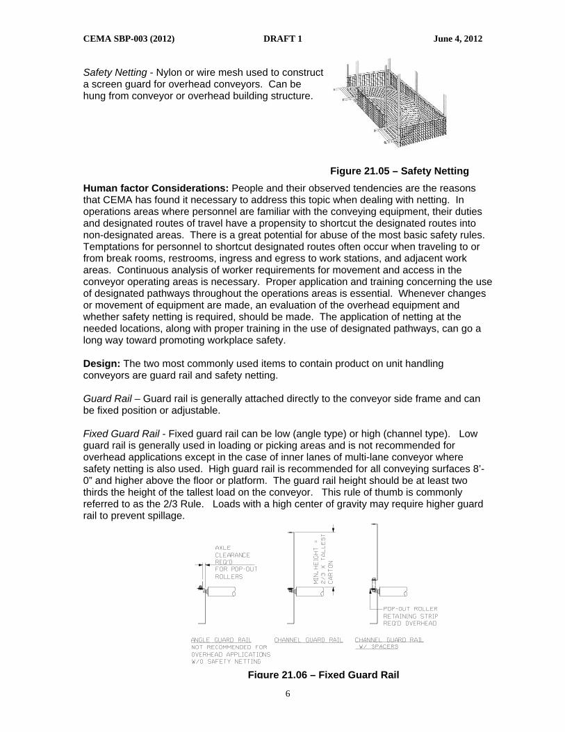
Safety Netting - Nylon or wire mesh used to construct a screen guard for overhead conveyors. Can be hung from conveyor or overhead building structure.
Figure 21.05 – Safety Netting
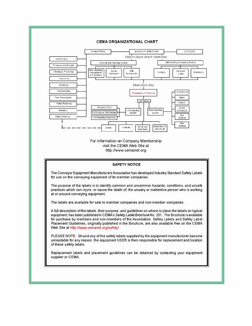
Human factor Considerations: People and their observed tendencies are the reasons that CEMA has found it necessary to address this topic when dealing with netting. In operations areas where personnel are familiar with the conveying equipment, their duties and designated routes of travel have a propensity to shortcut the designated routes into non-designated areas. There is a great potential for abuse of the most basic safety rules. Temptations for personnel to shortcut designated routes often occur when traveling to or from break rooms, restrooms, ingress and egress to work stations, and adjacent work areas. Continuous analysis of worker requirements for movement and access in the conveyor operating areas is necessary. Proper application and training concerning the use of designated pathways throughout the operations areas is essential. Whenever changes or movement of equipment are made, an evaluation of the overhead equipment and whether safety netting is required, should be made. The application of netting at the needed locations, along with proper training in the use of designated pathways, can go a long way toward promoting workplace safety. Design: The two most commonly used items to contain product on unit handling conveyors are guard rail and safety netting. Guard Rail – Guard rail is generally attached directly to the conveyor side frame and can be fixed position or adjustable. Fixed Guard Rail - Fixed guard rail can be low (angle type) or high (channel type). Low guard rail is generally used in loading or picking areas and is not recommended for overhead applications except in the case of inner lanes of multi-lane conveyor where safety netting is also used. High guard rail is recommended for all conveying surfaces 8’-0” and higher above the floor or platform. The guard rail height should be at least two thirds the height of the tallest load on the conveyor. This rule of thumb is commonly referred to as the 2/3 Rule. Loads with a high center of gravity may require higher guard rail to prevent spillage.
Figure 21.06 – Fixed Guard Rail

CEMA SBP-003 (2012) DRAFT 1 June 4, 2012
7
Adjustable Guard Rail - Adjustable guard rail can be adjusted both horizontally and vertically from the conveyor side frame for varying load widths and heights. Typically, the guard rail is clamped to support rods that in turn are clamped to the conveyor side frame. Adjustments are made by loosening the clamps, re-positioning the guard rail or support rods, and then re-tightening the clamps. Small channels in a single or double high configuration are generally used for adjustable guard rail. The guard rail(s) must be vertically positioned to contain the shortest and tallest loads on the conveyor. In some cases, it may be necessary to add a center guard rail to prevent certain loads from passing between the top and bottom guard rails. Safety Netting – The application of safety netting must be evaluated for each specific area of a conveyor system. Careful consideration should be given for conveyors over worker access areas and walkways. A combination of high guard rail and safety netting may be required in these areas, particularly when there is a possibility for load jams on the conveyor. Spillage from load jams generally occurs when loads continue to be driven into a jammed or stopped condition downstream. Curves, spurs, transfers, and merge areas downstream of belt conveyors are particularly vulnerable to load jams and should be appropriately safeguarded against spillage. Load spillage presents a particular hazard to personnel around and below the affected area. Design of netting systems is based upon the following parameters: Use fireproof materials whenever possible Common netting materials examples:
• Braided Nylon
• Polyethylene
• Wire
• Heavy gage construction grade plastic woven into a mesh pattern. Light gage plastic is not acceptable.
Mesh Size Material Capacity Cord Strength Fire Retardant
1” x 1” Nylon 1000 ft lb 190 lb X
Figure 21.07 – Adjustable Guard Rail
Figure 21.08 – Safety Netting

CEMA SBP-003 (2012) DRAFT 1 June 4, 2012
8
Load Size and Weight – Netting must be able to withstand impact of the maximum load weight falling from the top of the guard rail to the netting elevation. Capacity value from catalog must be greater than the impact generated by the maximum load falling the maximum distance to the netting.
lDistanceMaximumFaltonWeightMaximumCarCapacity ×>
Netting Height – The design must allow for sufficient space for several loads collecting in netting area. The height of the netting needs to be 2/3 the height of the tallest load which is often higher than the height of the guard rail. Mesh Size – Net mesh size determined by the smallest item to be contained. Netting mesh size should be small enough not to allow loads or conveyor rollers to pass through the netting. Recommended mesh size is typically 1” x 1”. This size will not allow any loose 1.9 inch diameter rollers to pass through the netting. Small items in totes or cartons need to be reviewed for ability to pass through netting mesh. Spacing of Supports – Spacing of supports for netting should minimize sag when loaded and allow for ample number of connection points to prevent failure of netting at maximum loading. Aircraft cable style mounting is recommended to distribute loading of netting at connection points. Connections should be made with snap hooks. The number and spacing of connections should be reviewed with netting manufacturers to obtain full strength of the netting. Signage – The safety netting system, including the netting and related hardware, is not designed to support personnel. Installations should provide signage warning personnel to keep off the safety netting.
Figure 21.09 – Netting Mesh

CEMA SBP-003 (2012) DRAFT 1 June 4, 2012
9
Design Considerations:
• Design the netting to support the heaviest product loads.
• Vertical netting can be used above the guard rail as an alternative to sheet metal.
• Netting must be removable for cleanout.
• Solid pans can be used for underguarding.
• Avoid the sharp edge commonly produced by cutting plastic net.
• When using plastic netting as under guarding as well a spill guarding consider that the plastic material can be deflected, allowing access to moving machinery. Minimize deflection by using fasteners at shorter intervals
Example Spill Guarding Configurations: These are not intended to exclude other methods Single Line -
• The space between conveyor side frame and netting must be equal to or greater than the conveyor between-frame (B.F.) dimension.
• The vertical netting must extend above conveyor guard rail a minimum of 2/3 the maximum load height.
Figure 21.10 – Single Line Spill Guarding Configuration
Multiple Lines -
• The spacing between parallel lines should be less than minimum load size.
• The space between the conveyor outer side frame and the netting must be equal to or greater than the conveyor between-frame (B.F.) dimension.
• The vertical netting must extend above the conveyor guard rail a minimum of 2/3 the maximum load height.

CEMA SBP-003 (2012) DRAFT 1 June 4, 2012
10
Figure 21.11 – Multiple Line Spill Guarding Configuration
Lines Supported on Platforms - A platform may serve as spill guarding if it properly protects areas below. Netting may be installed on the handrail to contain spilled loads.
Figure 21.12 – Lines Supported on Platforms

CEMA SBP-003 (2012) DRAFT 1 June 4, 2012
11
Lines Parallel to Catwalks - A catwalk may serve as spill guarding if it properly protects areas below. Netting may be installed on the handrail to contain spilled loads.
Figure 21.13 – Lines Parallel to Catwalks
90 Degree Transfers and Merges -
• Transfers and merges are more susceptible to load jams due to causes such as variation in load integrity, changes in direction of travel, and timing of conveyor equipment.
• The volume of loads that can be collected in these areas must be considered in the design of the netting system. Use of jam detection devices in such areas is recommended in addition to spill guarding.
Testing -
1. Determine where the weakest area(s) of the spill guarding is located. (There may be several such points in the netting system.)
2. Assemble a test load that simulates the maximum carton or load to be handled by the conveyor equipment.
3. Drop the load from the maximum height. Inspect the netting and connection points. The netting should return to its original shape. There must be no tears or fretting.
Inspection/Maintenance: To avoid overloading the netting system, remove spilled product immediately and inspect for damage to the netting system. Yearly inspections are necessary. Inspect all cabling and fasteners to make sure they are tight and secure. Inspections are also required any time work is performed in the area that requires removing or modifying the netting. Particular attention is required if welding or grinding is performed in the area.
END OF DOCUMENT

Conveyor Equipment Manufacturers Association (CEMA)
Safety Best Practices Recommendation
CEMA SBP-001 (2004)
Design and Safe Application of
Conveyor Crossovers for
Unit Handling Conveyors
Provided as a service to the Conveying Industry by the
CEMA Engineering Conference
Original Publication Date: June 1, 2004 Change 1: November 17, 2004
i.
TABLE OF CONTENTS
A. PURPOSE STATEMENT
B. DEFINITIONS
C. HUMAN FACTOR CONSIDERATIONS
D. GENERAL DESIGN PARAMETERS
CROSSOVERS AT CONVEYOR HEIGHT CROSSOVERS ABOVE THE CONVEYOR
E. APPLICATION
GENERAL APPLICATION GUIDE (CHART)
F. MECHANICAL SAFETY CONSIDERATIONS
G. CONTROLS
H. ADDITIONAL CONFIGURATIONS
DISCLAIMER
These considerations are advisory only. CEMA makes no warranties (express, implied or statutory) in connection with these considerations.
Users of the considerations specifically understand and agree that CEMA, its member companies, its officers, agents and employees shall not be liable in tort or contract - whether based on warranty, negligence, strict liability, or any other theory of liability - for any action or failure to act in respect to the design, erection, installation, manufacture, preparation for sale, characteristics, features of delivery of anything derived from, or covered by these consideration. By employing or otherwise referring to these considerations, it is the user’s intent and understanding to absolve and protect CEMA, its member companies, its successors, assigns, officers, agents and employees from any and all tort, contract or other liability.
CONVEYOR EQUIPMENT MANUFACTURERS ASSOCIATION 6724 Lone Oak Blvd
Naples, Florida 34109 Web Site: http://www.cemanet.org
CEMA Safety Best Practices Recommendation (SBP) No. 001-2004 - Copyright 2004
ii.
CHANGE RECORD Original Publication Date: June 1. 2004 Change 1: November 17, 2004
In response to many inquiries, we added the citation in the California Code of Regulations that CALOSHA uses to limit the types of allowable crossovers to the note at the bottom of page 6 to allow people to find the reference.

June 1, 2004 CEMA SBP 001-2004
1.
Design and Safe Application
of Conveyor Crossovers
for Unit Handling Conveyors
A. PURPOSE The purpose of this document is to outline a standardized approach to the devices and items routinely provided to allow personnel to cross unit handling material handling conveyors used in a typical warehouse or manufacturing facility. These approaches flow from the collective experience of the member companies of the Unit Handling Section of the Conveyor Equipment Manufactures Association (CEMA). They have been collected herein in to offer considerations for selection and use of crossovers as one means of creating a safer operating environment for people working with unit handling conveyor systems. Specific conditions will vary from application to application, as will the purposes and experience level of the personnel expected to use the crossovers. These varying conditions, purposes, and experience levels will affect the selection of the type and design of the equipment provided in any given situation. The interests of practicality, utility, and safety are of prime concern in evaluating any proposed design. B. DEFINITIONS The definitions of terms used within this standard will conform to those identified in CEMA Standard #102 “Conveyor Terms and Definitions”, except as re-defined within this section. Additional terms not currently found in CEMA 102 are be defined here. Conveyor Crossover - A device used to allow personnel to cross conveyors at designated and approved locations. Fill in Plates - Closely fitted plates positioned between the rollers, wheels or chains of powered or non-powered conveyors. These plates may be intended to be used as portions of a walk way, to provide a “steadying”/“resting” place, and or to prevent access to potential injury producing catch points. Ladder Crossover - A conveyor crossing device consisting of one or more ladders with support railings and, possibly, a platform that traverses the conveyor path. (See types 1 & 3)

June 1, 2004 CEMA SBP 001-2004
2.
Landing - A step or platform intended to allow someone to stand at that location while resting or waiting for a passage way to clear. Ship’s Stair - A stairway equipped with treads and stair rails with a slope of 50 to 70 degrees. It is sometimes referred to as a “ship’s ladder”. Stair Crossover - A conveyor crossing device, with a slope of less than 50 degrees, consisting of one or more stair step assemblies which may be joined together across the conveying surface by railings or railings and a platform or walkway. (Type 2 and 4) Step – to – Step Distance - The distance between two steps measured from trailing edge of the departure step to the leading edge of the arrival step. Stile - A generic term used to denote any crossing or “passing” device, sometimes used to denote a conveyor crossover. C. HUMAN FACTOR CONSIDERATIONS People and their observed tendencies are the reason that CEMA has found it necessary to address the need for crossovers. In operations areas where personnel are familiar with the conveying equipment, and their duties or routes of travel can require movement across conveyor paths, there is a great potential for abuse of the most basic safety rules. Temptations for these personnel to cross running and/or temporarily stopped conveyors are very strong. Experience has shown that accidents are inevitable under these conditions. Continuous analysis of worker requirements for movement and access in the conveyor operating areas is necessary. Proper application of crossovers at the “most needed” locations can go a long way towards promoting workplace safety when conditions would otherwise present the temptation to cross the conveyors in an unsafe manner. D. GENERAL DESIGN PARAMETERS There are two different types of elevated conveyor crossovers commonly used in industrial applications. These are the ladder and stair types. Each of these can be sub categorized by whether they allow crossing at conveyor height, or provide for crossing at an elevation which clears both the conveying surface and the highest item expected to be conveyed. All four designs should be lagged to the floor for safety and stability. When designing these crossovers, reference should be made, among others, to the following documents:
• ANSI Standard A1264.1 - “Safety Requirements for Workplace Floor and Wall Openings, Stairs and Railing Systems” http://www.ansi.org
• OSHA’s 29 CFR Part 1910.24 - “Fixed Industrial Stairs” http://www.osha.gov
• OSHA’s 29CFR Part 29CFR Part 1910.27 - “Fixed Ladders” http://www.osha.gov

June 1, 2004 CEMA SBP 001-2004
3.
CROSSOVERS AT CONVEYOR HEIGHT
Ladder - At conveying height (Type 1 Access Method) This crossover typically uses vertical ladders on both sides of the conveyor, and hand rails (without middle rail) traversing the conveyor. An angled ships ladder may also be used. This type requires the least floor and over the conveyor space. It is also the easiest to install. The use of both hands is required while climbing the ladder and while crossing the conveyor. This type of crossover is typically used by trained personnel for access to maintenance and for other operational purposes. Stair - At conveyor height (Type 2 Access Method) This type of stair crossover brings the walking surface height only up to the conveying surface height, or slightly above. There are routinely hand rails on one or both sides of both the stairs and the conveyor crossing area. The crossing area will usually not have an intermediate rail, allowing for clearance for the conveyable to pass under the hand rail. This type of stair crossover improves on the vertical space requirements of the Type 3 (see below), but may not meet fire code egress requirements in all areas. These units can be applied in lower ceiling heights and head clearance areas than is possible with full decked crossovers. They are easier to build and apply, and can be more easily moved when there are changes in conveyor or personnel travel paths. This is the most convenient type of crossover to use, since often a package can easily be carried in one hand, and there are few steps to negotiate. Personnel should be cautioned to cross only when conveyables are not present or immediately approaching on the conveyor. This is not unlike crossing the street or fork truck aisle, except the “traffic” is much slower, comes from only one direction, and the “pedestrian” has one or more hand rails available the entire way across. In some instances, there will be no opportunity to step on the conveyor surface. In these instances it will be necessary to step completely across the conveyor. On the wider (and some narrow) applications, surfaces suitable for walking or stepping will be provided. On a wide belt or slat conveyor, this will be accomplished by stopping the conveyor during passage and using the conveying surface itself as a walkway if necessary. In these instances, the control of the conveyor motion must be at the location of the passage. Those controls should be operated only by the person seeking passage.
June 1, 2004 CEMA SBP 001-2004
4.
CROSSOVERS ABOVE THE CONVEYOR
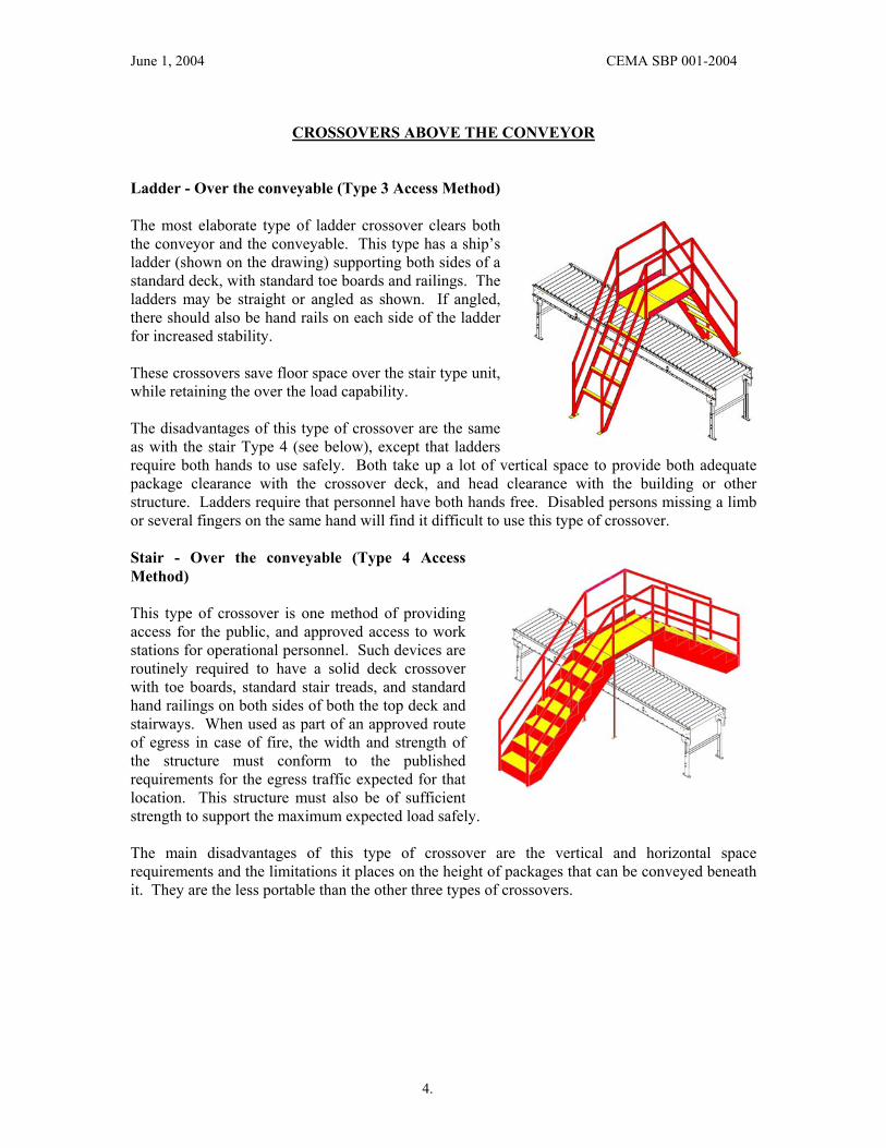
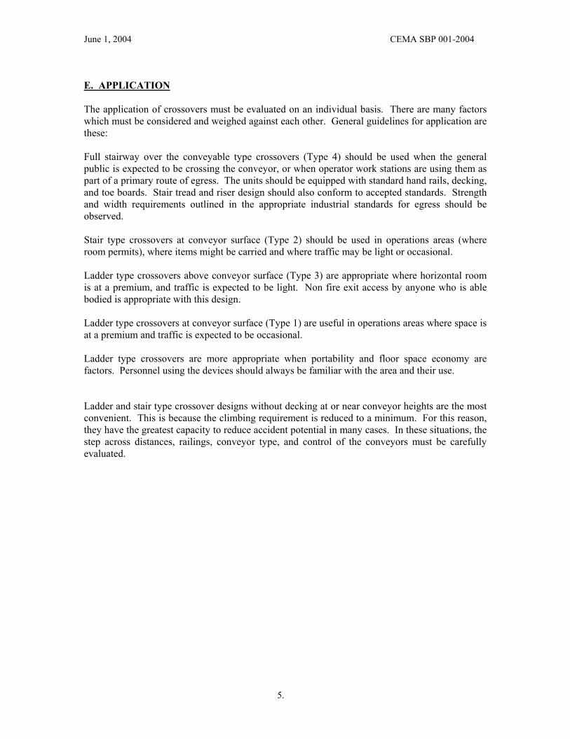
Ladder - Over the conveyable (Type 3 Access Method) The most elaborate type of ladder crossover clears both the conveyor and the conveyable. This type has a ship’s ladder (shown on the drawing) supporting both sides of a standard deck, with standard toe boards and railings. The ladders may be straight or angled as shown. If angled, there should also be hand rails on each side of the ladder for increased stability. These crossovers save floor space over the stair type unit, while retaining the over the load capability. The disadvantages of this type of crossover are the same as with the stair Type 4 (see below), except that ladders require both hands to use safely. Both take up a lot of vertical space to provide both adequate package clearance with the crossover deck, and head clearance with the building or other structure. Ladders require that personnel have both hands free. Disabled persons missing a limb or several fingers on the same hand will find it difficult to use this type of crossover. Stair - Over the conveyable (Type 4 Access Method) This type of crossover is one method of providing access for the public, and approved access to work stations for operational personnel. Such devices are routinely required to have a solid deck crossover with toe boards, standard stair treads, and standard hand railings on both sides of both the top deck and stairways. When used as part of an approved route of egress in case of fire, the width and strength of the structure must conform to the published requirements for the egress traffic expected for that location. This structure must also be of sufficient strength to support the maximum expected load safely. The main disadvantages of this type of crossover are the vertical and horizontal space requirements and the limitations it places on the height of packages that can be conveyed beneath it. They are the less portable than the other three types of crossovers.
June 1, 2004 CEMA SBP 001-2004
5.
E. APPLICATION The application of crossovers must be evaluated on an individual basis. There are many factors which must be considered and weighed against each other. General guidelines for application are these: Full stairway over the conveyable type crossovers (Type 4) should be used when the general public is expected to be crossing the conveyor, or when operator work stations are using them as part of a primary route of egress. The units should be equipped with standard hand rails, decking, and toe boards. Stair tread and riser design should also conform to accepted standards. Strength and width requirements outlined in the appropriate industrial standards for egress should be observed. Stair type crossovers at conveyor surface (Type 2) should be used in operations areas (where room permits), where items might be carried and where traffic may be light or occasional. Ladder type crossovers above conveyor surface (Type 3) are appropriate where horizontal room is at a premium, and traffic is expected to be light. Non fire exit access by anyone who is able bodied is appropriate with this design. Ladder type crossovers at conveyor surface (Type 1) are useful in operations areas where space is at a premium and traffic is expected to be occasional. Ladder type crossovers are more appropriate when portability and floor space economy are factors. Personnel using the devices should always be familiar with the area and their use. Ladder and stair type crossover designs without decking at or near conveyor heights are the most convenient. This is because the climbing requirement is reduced to a minimum. For this reason, they have the greatest capacity to reduce accident potential in many cases. In these situations, the step across distances, railings, conveyor type, and control of the conveyors must be carefully evaluated.

June 1, 2004 CEMA SBP 001-2004
6.
GENERAL APPLICATION GUIDE CHART
The following chart is a general application guideline for types of conveyors and associated crossover designs.
Conveyor Type
Step to Step Distance
33” or LessGreater Than
33"33” or Less
Greater Than 33"
33” or LessGreater Than
33"
Type 1 Access O - IAP O - IAP O - IAP O - IAP O - IAP O - IAP
Type 1 Method Step AcrossStep on
Stopped BeltStep Across Step On Plates
Step On Plates or Across
Step On Plates
Type 2 Access O - E O - E O - E O - E O - E O - E
Type 2 Method Step AcrossStep on
Stopped BeltStep Across Step On Plates Step Across Step On Plates
Type 3 Access P - E P - E P - E P - E P - E P - E
Type 3 MethodWalk On
DeckWalk On Deck Walk On Deck Walk On Deck Walk On Deck Walk On Deck
Type 4 Access P - E P - E P - E P - E P - E P - E
Type 4 MethodWalk On
DeckWalk On Deck Walk On Deck Walk On Deck Walk On Deck Walk On Deck
CROSSOVER SELECTION CHART
BELT ROLLER CHAIN
Legend
O = Occasional = Not for heavy traffic or the only access to a work station. P = Primary = Primary route of egress capable IAP = Informed Authorized Personnel E = Employee = Employee or others accompanied by an employee
Note – Be sure to consult state and local regulations before applying crossovers. For instance, as of 2004, California OSHA (CALOSHA) does not allow the use of Type 1 and Type 2 crossovers.
Ref (California Code of Regulations, Title 8, Section 7030 Conveyors, (d)) http://www.dir.ca.gov/title8/7030.html
November 17, 2004

June 1, 2004 CEMA SBP 001-2004
7.
F. MECHANICAL SAFETY CONSIDERATIONS At conveyor level crossovers where the conveyor is wider than 33” an intermediate step plate or plates of some kind should be considered. This is often possible on roller and chain conveyors, but not on belt or slat type conveyors. The purpose of these step plates is to provide a solid intermediate point for personnel to step while crossing the conveyor. Such plates will necessarily be slightly below the conveying surface. Care should be taken that the top steps on either side of the conveyor are no more than a few inches above the conveyor surface in these instances. Across the conveyor hand rails should be evaluated on an installation by installation basis when conveyor height crossovers are employed. In most instances a hand rail on each side of the travel path is the best option. When the conveyor is expected to be running when someone is crossing, the size and mass of the potential load should be evaluated with respect to potential injury involving the downstream hand rail. Stopping the conveyor while crossing is in process is also an option. G. CONTROLS Certain types of conveyors and conveying situations make it advisable to tie the conveyor control circuit into the conveyor crossing event. High speed conveyors, particularly those conveying heavy packages, should be considered for this option. Although the distance across the conveyor may be an easy step (33” or less) accidentally stepping on a running high speed conveyor may cause someone to loose their balance, even when holding two hand rails. For this reason, it might be advisable to provide a conveyor control switch on each side of the crossover to stop the conveyor prior to personnel crossing. Other situations which warrant this measure are Belt and slat conveyors over 33” wide. On this equipment, crossing the conveyor requires a step where no step is possible. Stopping the conveyor provides that step. Other situations which might indicate the need to shut down the conveyor prior to crossing would be solid, heavy bulky loads which might injure personnel. Another instance might be an expected very high number of loads moving on a wide conveyor, making finding a break to pass through “on the fly” difficult or impossible. In all of these situations, the exact control sequence should be evaluated closely. Unexpected start-up of the conveyor while personnel are crossing is unacceptable. Any control scheme should be closely evaluated under every conceivable situation for this possibility. To help determine the level of control and reliability for the control system, one should refer to ISO 13849-1 “Safety of Machinery – ‘Safety Related Parts of Control systems” Parts 1 and 100.

June 1, 2004 CEMA SBP 001-2004
8.
H. ADDITIONAL CONFIGURATIONS Multiple Conveyors and Platforms Where type 1 and 2 crossovers are utilized to cross multiple conveyors without returning to the walking/working surface, a landing or step of full width and minimum 8” deep will be provided between conveyors. Suitable rails or grab handles will be provided on both sides of the landing, if continuous hand rails across the conveyors and landings are not installed. Multiple conveyors separated by gaps greater than 12” will require that crossover railing systems comply with the kick plate and intermediate rail requirements of OSHA 29CFR 1910.27 and ASME A1264.1 if the elevation of the crossing surface exceeds 4’-0”. Obviously, this is necessary only at the locations where the deck or step transverses the clear distance between the conveyors. Ladder ways for ascending or descending to/from the conveyor elevation shall conform to the provisions of OSHA 29CFR 1910.27 and ASME A1264.1. Crossover ladder ways descending onto platforms which are 4’-0” or more above the next walking working surface shall employ one of the following fall arrest features:
• A landing extending at least 50” past the ladder base at right angles to the ladder rungs.
• An elevated backstop railing system such that a 50” or greater radius from vertical to horizontal radiating from the top step of the ladder will contact the backstop. Such backstop will conform to standard guard rail strength construction and strength requirements, except that there shall be no opening larger than 10” by 10”. The backstop shall extend to 1’-6” or more to each side of the ladder width, and have a total width not less than 5’6”. Structural members of the backstop shall conform to the 20” vertical by 8’ maximum open hole dimensions of the hand rail design. Lesser members of suitable strength may be used to reduce the openings to 10” X 10”or smaller.
• A standard ladder cage as prescribed in OSHA 29CFR 1910.27
END OF DOCUMENT

June 1, 2004 CEMA SBP 001-2004
6.
GENERAL APPLICATION GUIDE CHART
The following chart is a general application guideline for types of conveyors and associated crossover designs.
Conveyor Type
Step to Step Distance
33” or LessGreater Than
33"33” or Less
Greater Than 33"
33” or LessGreater Than
33"
Type 1 Access O - IAP O - IAP O - IAP O - IAP O - IAP O - IAP
Type 1 Method Step AcrossStep on
Stopped BeltStep Across Step On Plates
Step On Plates or Across
Step On Plates
Type 2 Access O - E O - E O - E O - E O - E O - E
Type 2 Method Step AcrossStep on
Stopped BeltStep Across Step On Plates Step Across Step On Plates
Type 3 Access P - E P - E P - E P - E P - E P - E
Type 3 MethodWalk On
DeckWalk On Deck Walk On Deck Walk On Deck Walk On Deck Walk On Deck
Type 4 Access P - E P - E P - E P - E P - E P - E
Type 4 MethodWalk On
DeckWalk On Deck Walk On Deck Walk On Deck Walk On Deck Walk On Deck
CROSSOVER SELECTION CHART
BELT ROLLER CHAIN
Legend
O = Occasional = Not for heavy traffic or the only access to a work station. P = Primary = Primary route of egress capable IAP = Informed Authorized Personnel E = Employee = Employee or others accompanied by an employee
Note – Be sure to consult state and local regulations before applying crossovers. For instance, as of 2004, California OSHA (CALOSHA) does not allow the use of Type 1 and Type 2 crossovers.
November 17, 2004
Ref (California Code of Regulations, Title 8, Section 7030 Conveyors, (d)) http://www.dir.ca.gov/title8/7030.html
joe.kirby
Typewritten text
For instance, ast of 2004, Califorina OSHA (Cal-OSHA) does not allow the use of Type 1 and Type 2 crossovers in the mining industry. Ref (Califorinia Code of Regulations, Title 8, Subchapter 17, Mine Safety Orders, Article 18, Conveyors and Tramways, Section 7030, (d) http://www.dir.ca.gov/title8/7030.html
joe.kirby
Cross-Out
joe.kirby
Cross-Out