Converting Abandoned Hungarian Oil and Gas Wells Into ... · Converting Abandoned Hungarian Oil and...
8
PROCEEDINGS, 43rd Workshop on Geothermal Reservoir Engineering Stanford University, Stanford, California, February 12-14, 2018 SGP-TR-213 1 Converting Abandoned Hungarian Oil and Gas wells into Geothermal Sources Aniko N. Toth 1 , Peter Szucs 2 , Jozsef Pap 1 , Attila Nyikos 3 and David K. Fenerty 3 1 Department of Petroleum and Natural Gas Engineering, University of Miskolc, Miskolc-Egyetemváros, 3515 Hungary 2 MTA-ME Geoengineering Research Group, Department of Hydrogeology and Engineering Geology, University of Miskolc 3 Hungarian Energy and Public Utility Regulatory Authority, Budapest, Bajcsy-Zsilinszky u. 52., 1057 Hungary [email protected] Keywords: Hungary, heat flow, geothermal, abandoned oil and gas well, EGS, numerical model. ABSTRACT Hungary’s excellent geothermal potential is well-known. Based on the 2016 Geothermal Atlas of Hungary, 1622 thermal wells produce hot water for direct heat utilization. The atlas also showed that many abandoned oil and gas wells were good possible sources of geothermal energy. This paper investigates the suitability of abandoned wells in Hungary for possible hydrothermal or Enhanced Geothermal Systems (EGS) applications. The study identifies 168 of the abandoned wells, characterized by medium to high terrestrial heat flows (75-100 mW/m 2 ), located for the most part in sedimentary layers and having to a lesser extent fractured geology. At a depth of 1000 m, the bottom hole temperatures are 40 to 69 o C. These rock temperatures are sufficient for low-temperature direct use such as district heating, greenhouse heating, and aqua-culture, all using either hydrothermal or EGS systems. The mitigation of drilling costs and the documented lithology can obviously and significantly reduce the risk associated with EGS. The feasibility of using these wells as deep BHE applications within abandoned hydrocarbon wells is demonstrated here with analytical and numerical models 1. INTRODUCTION Following a request from the Hungarian Energy and Public Utility Regulatory Authority, a study was made to analyze and summarize the geothermal potential of every one of the Hungary’s 19 counties. Based on this study ‘The Geothermal Atlas of Hungary’ was published in 2016. Along with Hungary’s 1622 registered geothermal wells, the atlas also considered more than 168 existing abandoned oil and gas wells. These abandoned wells were noted by Hungary’s Mining Utilization Company in the Public Interest as possible future geothermal sources. The purpose of this paper is to investigate and analyze the geothermal energy potential of these 170 abandoned oil and gas wells. The data provided by these wells also provides valuable subsurface regarding lithology, temperature, and formation porosity. For the purposes of developing a geothermal project, Dumas and Angelino (2015), and Wall and Dobson (2016) gave similar CAPEX breakdowns. Project stage Spending Exploration-Feasibility 13% Exploration-Drilling 6% Drilling 44% Field Gathering System 8% Plant Construction and Startup 30% Total 100% Table 1: Capex breakdown for a geothermal project Obviously, drilling wells is the highest-cost engineering component. To drill one 2.5-mile (4-kilometer) well, which is middle-range, costs about $5 million, per Augustine et al. (2006). Today, more than ten years later, the drilling cost would be about the same. 2. NATURE OF THE ABANDONED OIL AND GAS WELLS IN HUNGARY The 2016 Geothermal Atlas was based on various existing Hungarian geothermal databases. For this study we created five different isothermal maps of Hungary (at 30 o C, 50 o C, 60 o C, 70 o C and 90 o C) to show the different depths at which a particular rock temperature was attained. The higher the temperature the better, geothermally speaking, so we only analyzed abandoned wells at the 90 o C isotherm, as shown in. Fig. 1. It is evident that in the Alfold plain, in SE Hungary, 90 o C rock temperature is attained at 1600-1700 m. A noteworthy of these 168 wells, the largest group (48%) are 2000-3000 m deep, and the second largest group (29%) 1000-2000 m deep. A significant proportion (15%) are 3000-4000 m deep, and the deepest well is 5843 m. These wells were drilled between the 40s
Transcript of Converting Abandoned Hungarian Oil and Gas Wells Into ... · Converting Abandoned Hungarian Oil and...
PROCEEDINGS, 43rd Workshop on Geothermal Reservoir Engineering
Stanford University, Stanford, California, February 12-14, 2018
SGP-TR-213
1
Converting Abandoned Hungarian Oil and Gas wells into Geothermal Sources
Aniko N. Toth1, Peter Szucs
2, Jozsef Pap
1, Attila Nyikos
3 and David K. Fenerty
3
1 Department of Petroleum and Natural Gas Engineering, University of Miskolc, Miskolc-Egyetemváros, 3515 Hungary
2MTA-ME Geoengineering Research Group, Department of Hydrogeology and Engineering Geology, University of Miskolc
3Hungarian Energy and Public Utility Regulatory Authority, Budapest, Bajcsy-Zsilinszky u. 52., 1057 Hungary
Keywords: Hungary, heat flow, geothermal, abandoned oil and gas well, EGS, numerical model.
ABSTRACT
Hungary’s excellent geothermal potential is well-known. Based on the 2016 Geothermal Atlas of Hungary, 1622 thermal wells produce
hot water for direct heat utilization. The atlas also showed that many abandoned oil and gas wells were good possible sources of
geothermal energy. This paper investigates the suitability of abandoned wells in Hungary for possible hydrothermal or Enhanced
Geothermal Systems (EGS) applications. The study identifies 168 of the abandoned wells, characterized by medium to high terrestrial
heat flows (75-100 mW/m2), located for the most part in sedimentary layers and having to a lesser extent fractured geology. At a depth
of 1000 m, the bottom hole temperatures are 40 to 69 oC. These rock temperatures are sufficient for low-temperature direct use such as
district heating, greenhouse heating, and aqua-culture, all using either hydrothermal or EGS systems. The mitigation of drilling costs
and the documented lithology can obviously and significantly reduce the risk associated with EGS. The feasibility of using these wells
as deep BHE applications within abandoned hydrocarbon wells is demonstrated here with analytical and numerical models
1. INTRODUCTION
Following a request from the Hungarian Energy and Public Utility Regulatory Authority, a study was made to analyze and summarize
the geothermal potential of every one of the Hungary’s 19 counties. Based on this study ‘The Geothermal Atlas of Hungary’ was
published in 2016. Along with Hungary’s 1622 registered geothermal wells, the atlas also considered more than 168 existing abandoned
oil and gas wells. These abandoned wells were noted by Hungary’s Mining Utilization Company in the Public Interest as possible future
geothermal sources.
The purpose of this paper is to investigate and analyze the geothermal energy potential of these 170 abandoned oil and gas wells. The
data provided by these wells also provides valuable subsurface regarding lithology, temperature, and formation porosity. For the
purposes of developing a geothermal project, Dumas and Angelino (2015), and Wall and Dobson (2016) gave similar CAPEX
breakdowns.
Project stage Spending
Exploration-Feasibility 13%
Exploration-Drilling 6%
Drilling 44%
Field Gathering System 8%
Plant Construction and Startup 30%
Total 100%
Table 1: Capex breakdown for a geothermal project
Obviously, drilling wells is the highest-cost engineering component. To drill one 2.5-mile (4-kilometer) well, which is middle-range,
costs about $5 million, per Augustine et al. (2006). Today, more than ten years later, the drilling cost would be about the same.
2. NATURE OF THE ABANDONED OIL AND GAS WELLS IN HUNGARY
The 2016 Geothermal Atlas was based on various existing Hungarian geothermal databases. For this study we created five different
isothermal maps of Hungary (at 30 oC, 50 oC, 60 oC, 70 oC and 90 oC) to show the different depths at which a particular rock
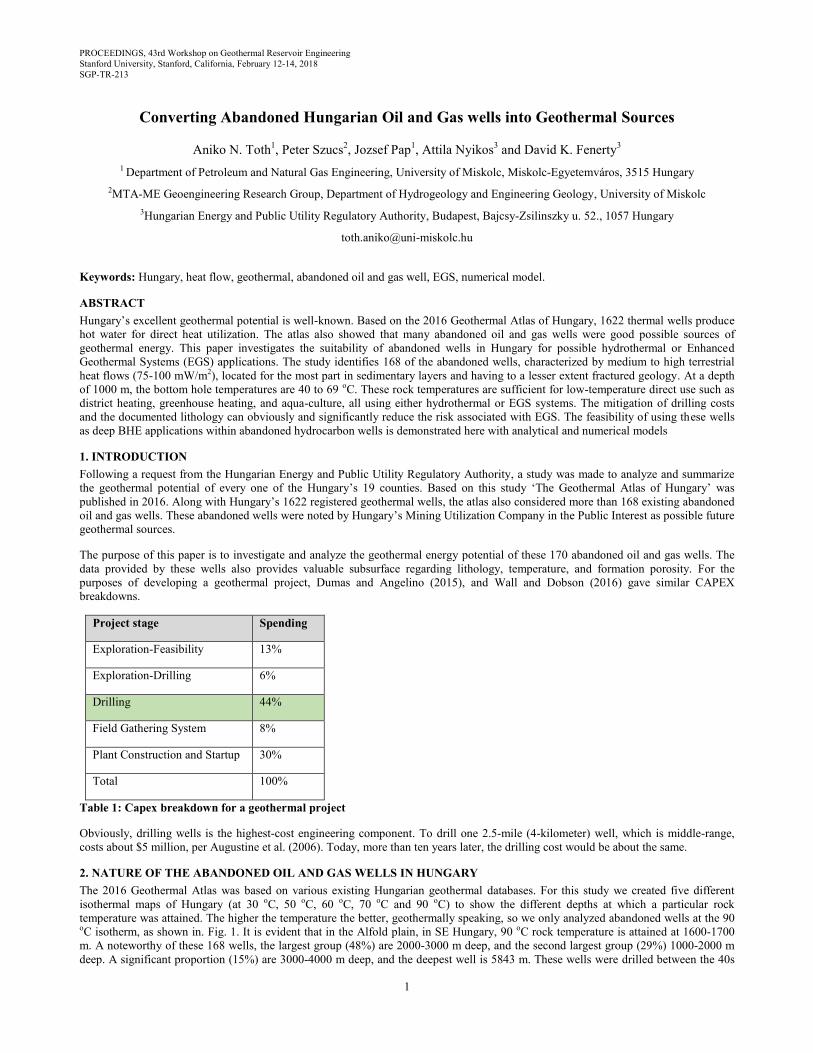
temperature was attained. The higher the temperature the better, geothermally speaking, so we only analyzed abandoned wells at the 90 oC isotherm, as shown in. Fig. 1. It is evident that in the Alfold plain, in SE Hungary, 90 oC rock temperature is attained at 1600-1700
m. A noteworthy of these 168 wells, the largest group (48%) are 2000-3000 m deep, and the second largest group (29%) 1000-2000 m
deep. A significant proportion (15%) are 3000-4000 m deep, and the deepest well is 5843 m. These wells were drilled between the 40s
Toth et al.
2
and 80s. There were two boom times for Hungarian oil and gas: the 60s and the s 80s. This age discrepancy means that theoretically the
condition of these wells could vary significantly. In practice, however, all these hydrocarbon-production, wells have the same
characteristics: a 30” conductor diameter set at a depth of 24 m, either driven or drilled and set with a piling augur; a surface casing of
20” casing set in a 26” diameter hole drilled to 80 m depth; an anchor casing of 13 3/8” with a casing set in a 171⁄2” hole drilled to 270
m depth; and a production casing of 9 5/8” with a casing set in a 12 1⁄4” hole drilled to 800 m depth, and a 7” open hole.
Figure 1: Abandoned oil and gas wells for the 90oC geo-isotherm (Toth, 2016)
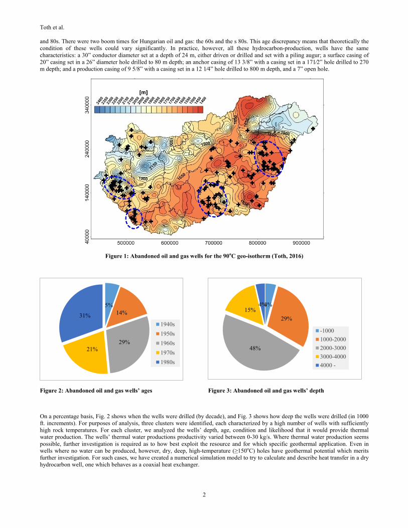
Figure 2: Abandoned oil and gas wells’ ages Figure 3: Abandoned oil and gas wells’ depth
On a percentage basis, Fig. 2 shows when the wells were drilled (by decade), and Fig. 3 shows how deep the wells were drilled (in 1000
ft. increments). For purposes of analysis, three clusters were identified, each characterized by a high number of wells with sufficiently
high rock temperatures. For each cluster, we analyzed the wells’ depth, age, condition and likelihood that it would provide thermal
water production. The wells’ thermal water productions productivity varied between 0-30 kg/s. Where thermal water production seems
possible, further investigation is required as to how best exploit the resource and for which specific geothermal application. Even in
wells where no water can be produced, however, dry, deep, high-temperature (≥150oC) holes have geothermal potential which merits
further investigation. For such cases, we have created a numerical simulation model to try to calculate and describe heat transfer in a dry
hydrocarbon well, one which behaves as a coaxial heat exchanger.
5%
14%
29%
21%
31%
1940s
1950s
1960s
1970s
1980s
4%
29%
48%
15% 4%
-1000
1000-2000
2000-3000
3000-4000
4000 -
Toth et al.
3
3. NUMERICAL SIMULATION MODEL OF A DRY HUNGARIAN HYDROCARBON WELL
ARMSTEAD (1983) suggested circulating water in a closed well. The water would flow downward through the annular space between
the casing and the tubing, and upward through the production tube, as it warms up. This heat extraction method produces no thermal
water production, and would be more environmentally friendly than any other form of geothermal energy production. One such
experimental production unit was installed in Hungary near Szolnok, in 1989. The results, as expected, were rather modest because of
the small heat transfer area of the system (BOBOK et al 1991). In 2008 Bobok and Toth introduced a mathematical model for such a
system, one which would predict its thermal behavior, so as to obviate further inefficient and expensive experiments and to show the
range of the dry hole utilization.
This paper’s objective is to show our new transient numerical model for a coaxial heat exchanger retrofitted to one of these wells, a
model based on the selected well’s exact technical data. We looked for a well with the most favorable characteristics, based on our data.
3.1 Physical parameters of the model
The well we chose was Ber-1, situated in SW Hungary, in a positive geothermal anomaly where the geothermal gradient (53 C/km)
exceeds the continental average, as shown in Fig. 4. Because no temperature data was available, we had to obtain the necessary data by
interpolation of geo-isothermal maps, where we could determine the geothermal gradient data. As the well is situated in a series of
sedimentary rock layers with relatively uniform thermodynamic properties, we assumed that the geothermal gradient increases linearly
from top to the bottom.
Figure 4: Abandoned wells in SW Hungary Figure 5: Temperature data obtained from geo-
isothermal maps at increasing depths
The simplified grid model of a closed geothermal well is shown in Fig. 6. The casing is closed at the bottom without any perforations.
The water flows downward through the annulus between the coaxial casing and tubing. Since the adjacent rock is warmer than the
circulating water, the water temperature increases in the direction of the flow. An axisymmetric thermal inhomogeneity is developed
around the well together with a radial heat conduction toward the well. This is the heat supply of the system. The warmed up water
flows upward through the tubing while its temperature slightly decreases, at a rate which depends mainly on the heat conduction
coefficient of the tubing. The system is analogous to a countercurrent heat exchanger. The main difference is that the adjacent rock
temperature distribution increases with increasing depth.
This model was calculated with the help of FlexPDE, a powerful finite-element solver which uses the Galerkin finite element method to
calculate from point to point within the mesh, using a pre-determined equation (PDE, 2011). Within the software, a unique source-code
input was given, which contained all necessary data (thermo-physical properties of different materials, geometries, inlet velocity of the
working fluid, input temperature data, the modified heat equation and the boundary conditions).
The model itself uses the well’s 7” outer casing as a direct heat transmitter to the flowing fluid, which flows down at a pre-determined
velocity. The fluid then rises through the inner insulated tubing at a speed proportional to the areas of the outer annulus and the inner
pipe. In static conditions, the thermal environment around the wellbore is uniform horizontally, as the model gets continuous heat stress
from the mantle of the lithology cylinder.
The model is based on Fourier’s law and assumes a homogeneous thermal conductivity, resulting in a three dimensional heat equation in
Cartesian coordinates:
1
𝑟𝑑𝑟(𝑘 ∗ 𝑟 ∗ 𝑑𝑟(𝑇)) + 𝑑𝑧(𝑘 ∗ 𝑑𝑧(𝑇)) = 𝜌 ∗ 𝑐 ∗ 𝑑𝑡(𝑇) + 𝜌(𝑤𝑎𝑡𝑒𝑟) ∗ 𝑐(𝑤𝑎𝑡𝑒𝑟) ∗ 𝑣 ∗ 𝑑𝑧(𝑇) (1)

Toth et al.
4
where r is the radial coordinate, z is the vertical coordinate, k is the thermal conductivity, c is the specific heat and 𝜌 is the density of the
given material, v gives the velocity of the flowing water, and T gives the temperature at the given point.
According to geological reports, 4 different characteristic layers can be found in the area, which we also implemented into the
simulation model. For insulation, we used aerogel foam as an insulation material around the tubing, with a thickness of 0.02 m. The
thermodynamics properties of the model-specific materials are summarized in Table 1.
The numerical mesh of the model contained almost 12500 node points on the 2D cylindrical coordinate system, with increasing
resolution in the well section from the outer boundary, providing a more accurate result. Before the actual series of simulations started,
we made some initial models with different radiuses. Based on work by Noorollahi et al. (2015), we made a sensitivity analysis to
determine the optimum model-boundary. As the outflowing temperature did not increase significantly after r=40 m, we have set that
value for the outer boundary of the model.
Material Name Specific heat
(J/kgC)
Thermal conductivity
(W/mK)
Density
(kg/m3)
Sand 935 2.3 2600
Sandstone 920 2.9 2720
Limestone 910 2.8 2700
Andesite 1160 2.6 2360
Water 4200 0.608 1000
Aerogel foam 2000 0.025 110
Steel 490 54.00 7850
Table 1: Thermal properties of different materials used in the simulation model
There was an additional 40 m rock layer under the heat exchanger, which provided heat stress from the region under the wellbore. The
model was distorted to the Z direction by 1/100, so as to make the output thermal drawdown plots more visible.
Figure 6: Numerical mesh of the model
It is important to mention that in a real life the construction of a hydrocarbon well requires adding several layers of pipe and cement. To
provide a stable simulation and a well-defined mesh with the appropriate results, however, we did not assume the average well’s
telescopic structure. As a result, our model consists of 7 different materials, with 9 sub-geometry sections (steel was defined to be both
casing and tubing material, and water was defined as belonging to both the annular and the inner fluid columns).

Toth et al.
5
3.2 Simulation Results
The temperature of the inlet water was set to 20 C. The static water-column in the heat exchanger was heated up by the lithology at
initial conditions, and when production started, the outflowing temperature was measured at the surface. After the working fluid from
the well bottom was produced, we measured a constantly decreasing temperature. The simulations were run with four different
outflowing velocities: 0.5 m/s, 0.75 m/s, 1.0 m/s and 1.5 m/s. The data were continuously recorded for 10 years. The simulation results
are summarized in Table 2 and in Fig. 7-10.
Simulation Velocity
(m/s)
Maximal outflow
temperature (C)
Outflow temperature
after 10 years (C)
Total obtained heat
after 10 years (kW)
1. 0.50 171.32 89.66 423.29
2. 0.75 176.12 74.48 484.98
3. 1.00 178.49 64.81 531.74
4. 1.50 180.58 52.14 572.23
Table 2: Simulation results
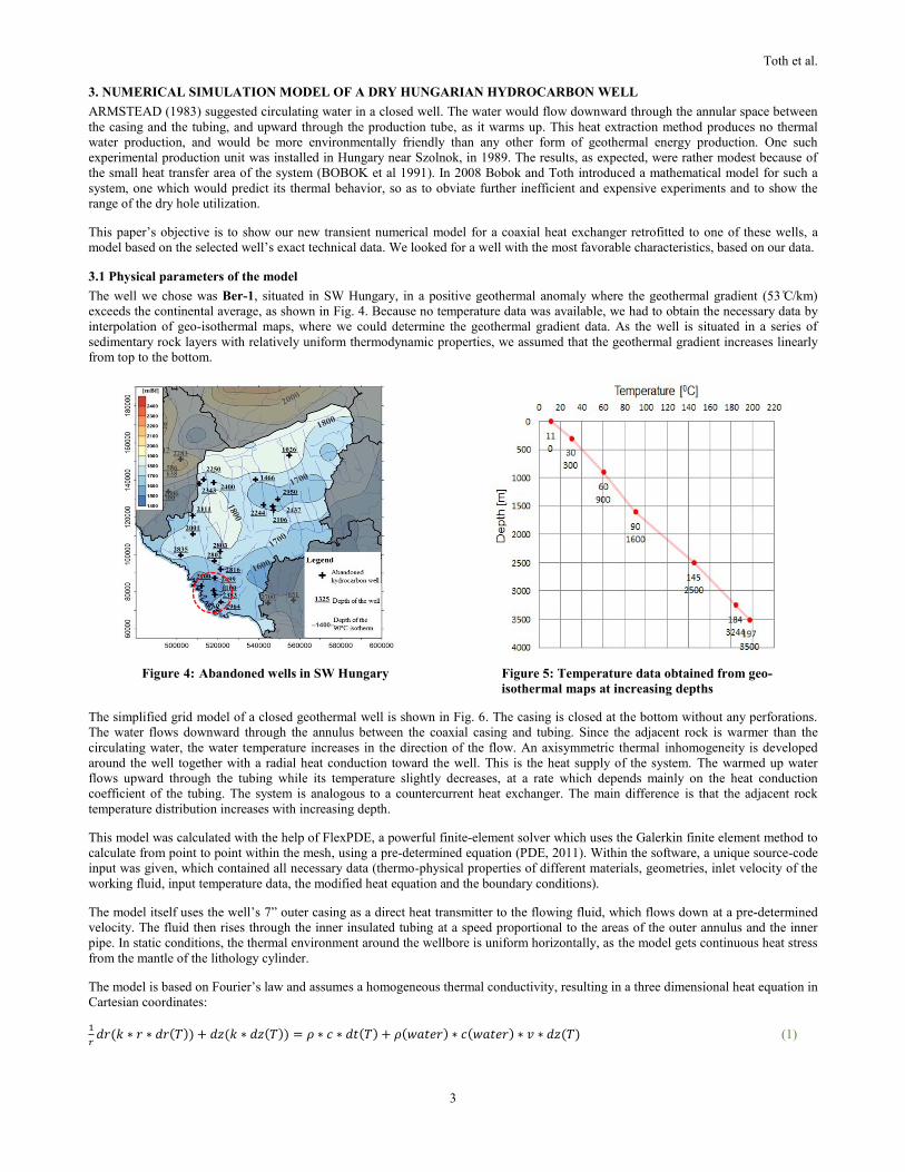
To determine the total heat transfer, we multiplied the calculated mass flow rate by the temperature difference and the specific heat of
the water. Based on our results, lower mass flow rate results in an increasing outflow temperature, but the total obtained power is higher
at increased velocities, as Fig. 8 shows.
Figure 7: Comparison of different outflow velocities as a function of outlet temperature and time
Figure 8: Comparison of output power as a function of outlet temperature and time
Toth et al.
6
Figure 9: Output power after 10 years, for the simulated output mass flow rates
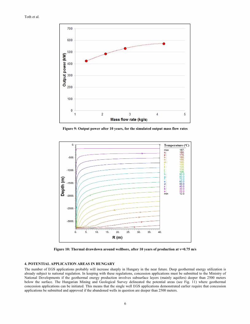
Figure 10: Thermal drawdown around wellbore, after 10 years of production at v=0.75 m/s
4. POTENTIAL APPLICATION AREAS IN HUNGARY
The number of EGS applications probably will increase sharply in Hungary in the near future. Deep geothermal energy utilization is
already subject to national regulation. In keeping with these regulations, concession applications must be submitted to the Ministry of
National Developments if the geothermal energy production involves subsurface layers (mainly aquifers) deeper than 2500 meters
below the surface. The Hungarian Mining and Geological Survey delineated the potential areas (see Fig. 11) where geothermal
concession applications can be initiated. This means that the single well EGS applications demonstrated earlier require that concession
applications be submitted and approved if the abandoned wells in question are deeper than 2500 meters.
Toth et al.
7
Figure 11: Delineated geothermal concession areas in Hungary
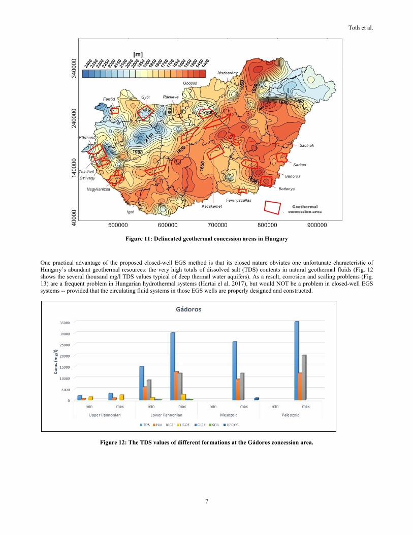
One practical advantage of the proposed closed-well EGS method is that its closed nature obviates one unfortunate characteristic of
Hungary’s abundant geothermal resources: the very high totals of dissolved salt (TDS) contents in natural geothermal fluids (Fig. 12
shows the several thousand mg/l TDS values typical of deep thermal water aquifers). As a result, corrosion and scaling problems (Fig.
13) are a frequent problem in Hungarian hydrothermal systems (Hartai el al. 2017), but would NOT be a problem in closed-well EGS
systems -- provided that the circulating fluid systems in those EGS wells are properly designed and constructed.
Figure 12: The TDS values of different formations at the Gádoros concession area.

Toth et al.
8
Figure 13: Corrosion and scale problems can occur frequently in Hungary hydrothermal systems.
CONCLUSIONS
With a reliable simulation model, it is possible to give an approximation of the expected outflowing water temperature from a coaxial
heat exchanger retrofitted to a dry hydrocarbon well. Although the model assumes a horizontally homogenous lithology structure around
the wellbore, and does not consider any fractures and groundwater effects in surface regions, this model can be a good basis for further
investigation. The insulation of the outer pipe sections in a real well could provide a fundamental benefit as well, as it would reduce the
initial heat loss of the inlet water (especially at higher water temperatures). The effect of different pipe diameters, well geometries,
geothermal gradients and different insulation materials can also influence the performance of our heat exchanger. For a more detailed
summary of how those additional parameters would affect our model, we would have to run several more detailed simulations.
Looking over the 168 abandoned oil and gas wells we have chosen to analyze, it’s evident that they have many different properties and
conditions, and represent various levels of potential thermal-water production or dry-hole EGS utilization. This paper is just the first
step in evaluating and estimating the value of this important potential source of renewable and import-independent energy. The next step
is to actually use our information and modelling techniques to set up a real-life demonstration site in one of these geothermally
promising localities.
REFERENCES
Augustine, C., Tester, J.W., Anderson, B. and Petty, S.: A comparison of geothermal with oil and gas well drilling costs. Proceedings,
31st Workshop on Geothermal Reservoir Engineering (2006),
Bobok E., Mating, B., Navratil, L. and Turzo Z.: Heat mining without water production (in Hungarian), Koolaj es Foldgaz, Volume 20,
(1991), 161-169
Bobok E. and Toth A.: Geothermal Energy from Dry Holes, Proceedings, 33rd Workshop on Geothermal Reservoir Engineering ,
Stanford University, Stanford, CA (2008),
Dumas, P., Angelino, L.: GEOELEC: Develop Geothermal Electricity in Europe, 40th Workshop on Geothermal Reservoir Engineering,
Stanford University, Stanford, CA (2015),
Hartai, E., Bodó, B., Madarász, T., Földessy, J., Norbert Németh, Kolencsikné Tóth, A., Szűcs, P., Szanyi, J., Osvald, M., Medgyes, T.,
Kóbor, B., Fernandez, i., Correia, V., Stein, A., Bisevac, V., Harðardóttir, V., Thorbjörnsson, I., Weisenberger, T., Rochelle, C.,
Lusty, P., Shaw, R., Kilpatrick, A., Ramalho, E., Matos, J., Carvalho, J., Dominguez, X., Laenen, B., Helsen, J., Cseko, A.,
Miklovicz, T., Tiess, G., Tiewsoh, L., Persa, D., Marincea, S., Costea, C., Fransaer, J., Palaniappan, R., Schwarz, G., Erlstrom, M.,
Thunholm, B., Ripa, M.: Combining energy production and mineral extraction – The CHPM2030 project. EUROPEAN
GEOLOGIST (43), (2017), 6-9
Noorollahi, Y., Pourarshad, M., Jalilinasrabady, S. and Yousefi, H.: Numerical simulation of power production from abandoned oil
wells in Ahwaz oil field in southern Iran - Elsevier, Geothermics, Volume 55, (2015), 16-23
PDE Solutions Inc. FlexPDE 6. PDE Solutions Inc.; 2011
Templeton, J.D., Ghoreishi-Madiseh, S.A., Hassani, J.D. and Al-Khawaja M.J.: Abandoned petroleum wells as sustainable sources of
geothermal energy, Elseviere, Energy, Volume 70, 1 (2014), 366-373
Toth, A.: Magyarország geotermikus atlasza, Study for the Hungarian Energy and Public Utility Regulatory Authority, (2016)
Toth, A.: The geothermal atlas of Hungary, ISBN 978-963-12-8459-1, Hungarian Energy and Public Utility Regulatory Authority,
(2016), 125-133
Toth, A.: Creating a Geothermal Atlas of Hungary, 42nd Workshop on Geothermal Reservoir Engineering, Stanford University,
Stanford, CA (2017)
Wall, A. M and Dobson, P. F.: Refining the Definition of a Geothermal Exploration Success Rate, Proceedings, 41st Workshop on
Geothermal Reservoir Engineering Stanford University, Stanford, CA (2016)