Conventional Question Practice Program
16
Office : F-126, Katwaria Sarai, New Delhi-110016 (Phone : 011-41013406, 7838813406, 9711853908) Website : www.iesmaster.org E-mail: [email protected] Conventional Question Practice Program Date: 23 rd April, 2016 1. (d) 2. (a) 3. (d) 4. (a) 5. (b) 6. (a) 7. (c) 8. (a) 9. (d) 10. (b) 11. (a) 12. (a) 13. (b) 14. (d) 15. (a) 16. (d) 17. (a) 18. (a) 19. (c) 20. (b) 21. (d) 22. (c) 23. (c) 24. (c) 25. (a) 26. (b) 27. (b) 28. (a) 29. (a) 30. (b) 31. (a) 32. (b) 33. (c) 34. (d) 35. (d) 36. (d) 37. (d) 38. (c) 39. (c) 40. (a) 41. (b) 42. (a) 43. (c) 44. (b) 45. (c) 46. (a) 47. (a) 48. (c) 49. (c) 50. (a) 51. (c) 52. (b) 53. (c) 54. (c) 55. (b) 56. (b) 57. (c) 58. (d) 59. (d) 60. (d) 61. (b) 62. (b) 63. (b) 64. (c) 65. (a) 66. (a) 67. (b) 68. (d) 69. (a) 70. (d) 71. (b) 72. (b) 73. (c) 74. (d) 75. (a) 76. (a) 77. (a) 78. (c) 79. (c) 80. (b) 81. (c) 82. (d) 83. (a) 84. (b) 85. (d) 86. (a) 87. (d) 88. (a) 89. (a) 90. (d) 91. (b) 92. (c) 93. (b) 94. (b) 95. (b) 96. (c) 97. (a) 98. (a) 99. (a) 100. (b) 101. (a) 102. (d) 103. (d) 104. (c) 105. (a) 106. (d) 107. (a) 108. (d) 109. (d) 110. (c) 111. (c) 112. (d) 113. (c) 114. (b) 115. (a) 116. (d) 117. (b) 118. (a) 119. (c) 120. (c) ANSWERS
Transcript of Conventional Question Practice Program

Office : F-126, Katwaria Sarai, New Delhi-110016 (Phone : 011-41013406, 7838813406, 9711853908)
Website : www.iesmaster.org E-mail: [email protected]
Conventional Question Practice ProgramDate: 23rd April, 2016
1. (d)
2. (a)
3. (d)
4. (a)
5. (b)
6. (a)
7. (c)
8. (a)
9. (d)
10. (b)
11. (a)
12. (a)
13. (b)
14. (d)
15. (a)
16. (d)
17. (a)
18. (a)
19. (c)
20. (b)
21. (d)
22. (c)
23. (c)
24. (c)
25. (a)
26. (b)
27. (b)
28. (a)
29. (a)
30. (b)
31. (a)
32. (b)
33. (c)
34. (d)
35. (d)
36. (d)
37. (d)
38. (c)
39. (c)
40. (a)
41. (b)
42. (a)
43. (c)
44. (b)
45. (c)
46. (a)
47. (a)
48. (c)
49. (c)
50. (a)
51. (c)
52. (b)
53. (c)
54. (c)
55. (b)
56. (b)
57. (c)
58. (d)
59. (d)
60. (d)
61. (b)
62. (b)
63. (b)
64. (c)
65. (a)
66. (a)
67. (b)
68. (d)
69. (a)
70. (d)
71. (b)
72. (b)
73. (c)
74. (d)
75. (a)
76. (a)
77. (a)
78. (c)
79. (c)
80. (b)
81. (c)
82. (d)
83. (a)
84. (b)
85. (d)
86. (a)
87. (d)
88. (a)
89. (a)
90. (d)
91. (b)
92. (c)
93. (b)
94. (b)
95. (b)
96. (c)
97. (a)
98. (a)
99. (a)
100. (b)
101. (a)
102. (d)
103. (d)
104. (c)
105. (a)
106. (d)
107. (a)
108. (d)
109. (d)
110. (c)
111. (c)
112. (d)
113. (c)
114. (b)
115. (a)
116. (d)
117. (b)
118. (a)
119. (c)
120. (c)
ANSWERS

IES M
ASTER
(2) ME (Test-17), Objective Solutions, 23rd April 2016
Sol–1: (d)Fanno flow is the flow in the absence ofheat and work transfer but with friction.The examples of fanno flow are- Flow in air conditioning ducts. Insulated pipes carrying gases and
steamSol–2: (a)
The schematic of a normal shock alongwith various parameters
(Decrease)
(where 'v' isvelocity)
P2T2 2(Increase)
v2, v2
P1V T1 1 1 1
P2,V T2 2 2 1, v
Shock
P1,V T1 1, 1 1,
Properties variation across shock
The flow before normal shock must besupersonic and it turns to subsonic downthe shock.
Sol–3: (d)Since spherical roller bearing can takehigh radial and axial loads, but theangular misalignment can be adjusted bythis bearing only (not by ball bearing). Soangular misalignment is decidingcriterion.
Sol–4: (a)Hydrodynamic lubrication has metal tometal contact at low speeds and no metalto metal contact at high speeds.Hydrostatic lubrication has no metal tometal contact even at low speeds. Thislubrication is provided by pump whichcreates high pressure to balance theweight of part.Boundary lubrication has partial metal tometal contact.
Sol–5: (b)
dp = 0.25
d
p
Tearing efficiency of riveted joints is theratio of minimum strength of the jointagainst failure by tension, shear to thatof member without a joint
tearing =P d
P
= d1P
tearing 0.75
Sol–6: (a)Rigid coupling are of two types dependingupon the clearance of holes and boltsconnecting flanges of two shafts. So ifthere is clearance, then the frictionbetween flange surfaces caused by bolttension is driving factor. In case there isclearance, the bolt connecting flangesundergoes shear and bending.
Sol–7: (c)Given,
Syt = 500 MPaSut = 700 MPa
t = 8 mm b = 20 mmd = 3 mm
Maximum transverse tensile load,P = yield strength × Effective area
= Syt × (b–d) × t= 500 × (20 – 3) × 8= 68000 N
P 68 kN
Sol–8: (a)In ductile material local yielding increasesthe area of crack ends and distribute stressconcentration to lower value.
Sol–9: (d)Aluminium is a ductile material. Hence,maximum shear stress theory should beused for aluminium components.

IES M
ASTER
(3) ME (Test-17), Objective Solutions, 23rd April 2016
Sol–10: (b)Theoritical stress connection factor,
kt = max
n
kt = 1 + 2ab
Since, the plate has circular cavityP
2a2b
P a = b = 5 mm
kt = 3 max = kt n
= 3 × 95max = 285 MPa
Sol–11: (a)Effectiveness of the fin is defined as theratio of heat transfer rate with fin to theheat transfer rate without fin.
=
with fin
without fin
If fins are thin and closely spaced thenmore number of fins can be accomodatedin a given space, more number of finsmeans more area for heat transfer. Henceqwith fin will be higher. Therefore fin effec-tiveness will be higher for option (a).
Sol–12: (a)Lumped heat transfer analysis is validwhen Biot Number is < 0.1
conductioni
convection
RBiot Number, BR
Sol–13: (b)Given, counter flow heat exchanger.
T = 60° Chi
T = 30° Cce T he
Tci
Heat transfer between fluids,
c pc cm c T = h ph hm c T
10 × 4 × cT = 2 × 20 × hT
cT = hT
LMTD = i eT T
iT = hi ceT T
= 60 – 30 = 30°
LMTD 30 C
Sol–14: (d)Across an isentropic flow, the stagnationtemperature, stagnation pressure andstagnation density remain constant.
Sol–15: (a)Heat transfer coefficient of various casesin increasing order1. Conduction in air
0.1 – 0.2 W/m-K2. Free convection
2 – 25 W/m-K3. Forced convection
25 – 250 W/m-K4. Boiling/condensation 2500 – 100000
W/m-KSol–16: (d)
1. Subcooled or saturated boiling in theabsence of bulk fluid flow is called poolboiling.
2. If subcooled or saturated fluid has bulkfluid flow during boiling, the boiling iscalled as flow boiling or forcedconvection boiling.Note: Sub cooled boiling means meanbulk temperature of fluid is less thansaturated temperature and heatingsurface temperature is more thansaturated temperature. Saturatedboiling means mean bulk tempera-ture equal to saturated temperature.
Sol–17: (a)If cooling rate is less, coarse pearlite forms(thickness of ferrite and cementite layer),more time for diffusion and favourables

IES M
ASTER
(4) ME (Test-17), Objective Solutions, 23rd April 2016
temperature gradient.Sol–18: (a)
Since heat dissipated from free end fromis negligible so,
q = x=
dTkdx l
0 = x =
dTkdx l
k cannot be zero, so
x =
dTdx l
= 0
Hence temperature gradient at tip of finis zero.
Sol–19: (c)Theoretical mechanical efficiency of a jetengine is maximum when the vehiclespeed approaches the magnitude of rela-tive velocity of gases at nozzle exit.
Sol–20: (b)Fuel is incompressible hence its densitywill remain same even at higher attitudesand density of air flowing throughcarburettor changes. So,
Altitude
ground
Air fuel ratioAir fuel ratio =
air Altitude
air ground
Altitude
ground
AFR 1AFR 2
Sol–21: (d)When a material has different propertiesin different direction, it is said to beanisotropic. In rolling, due to grainorientation along the rolling direction itleads to anisotropy.
Sol–22: (c)Isotropic: identical properties in alldirection.Homogeneous: similar propertythroughout the VolumeVisco-elastic: Time dependent stress-strain curveBrittle: No plastic zone because failure
strain is within elastic limit.Here A— 3 ; B — 4
C —1 ; D — 2Sol–23: (c)
Coefficient of thermal expansion of brassis more than steel, so brass will try toexpand more but it’s expansion will berestrained by steel because both will movetogether by same amount. Therefore brasswill be in compression and steel in tension.
Sol–24: (c)E = 2G (1+ )
Sol–25: (a)Radius of Mohr Circle
R =
2x y 2
xy2
=
2110 30 302
= 50 MPa
Principal Stress
1 =
x y R2
=
110 30 502
= 120 MPa
2 =
y R2
x = 110 30 502
= 20 MPaSol–26: (b)
Normal stress,n = PA =
27850
104
= 99.94
Major principal stress, 1 100 MPaNormal stress in other twoperpendicular plane = 0
Minor principal stress = 0Maximum shear stress under uniaxial tension
max =2 = 50 MPa
Sol–27: (b)In biaxial strain system, xy is shearingstrain and x and y are principal strain,then
xy2 =
x y2
IES M
ASTER
(5) ME (Test-17), Objective Solutions, 23rd April 2016
xy = x – ySol–28: (a)
As per max. distortion energy theory.Maximum shear strain energy in a bodyshould be less than or equal to maximumshear strain energy under uniaxial loading
Sol–29: (a)In circular shaftMaximum normal stess due to Bendingmoment
1 = 332 M
dMaximum shear stress due to Torsion T
= 3
16Td
Maximum normal stress due to combinedaction of Bending moment and Torque
max =2
21 1
2 2
= 2 23
16M M Td
According to maximum principal stresstheory, for no failure
max Allowable stress
2 23
16M M Td
3d 2 216 [M M T ]
Sol–30: (b)
For brittle materials, Normal stress theoryor Rankine theory gives best result.
Tresca’s theory is very closelysubstantiated by experimental results.
For max shear stress theory.2/fy
1
–1 1 1/fy
–1
No yielding
Failure by yielding
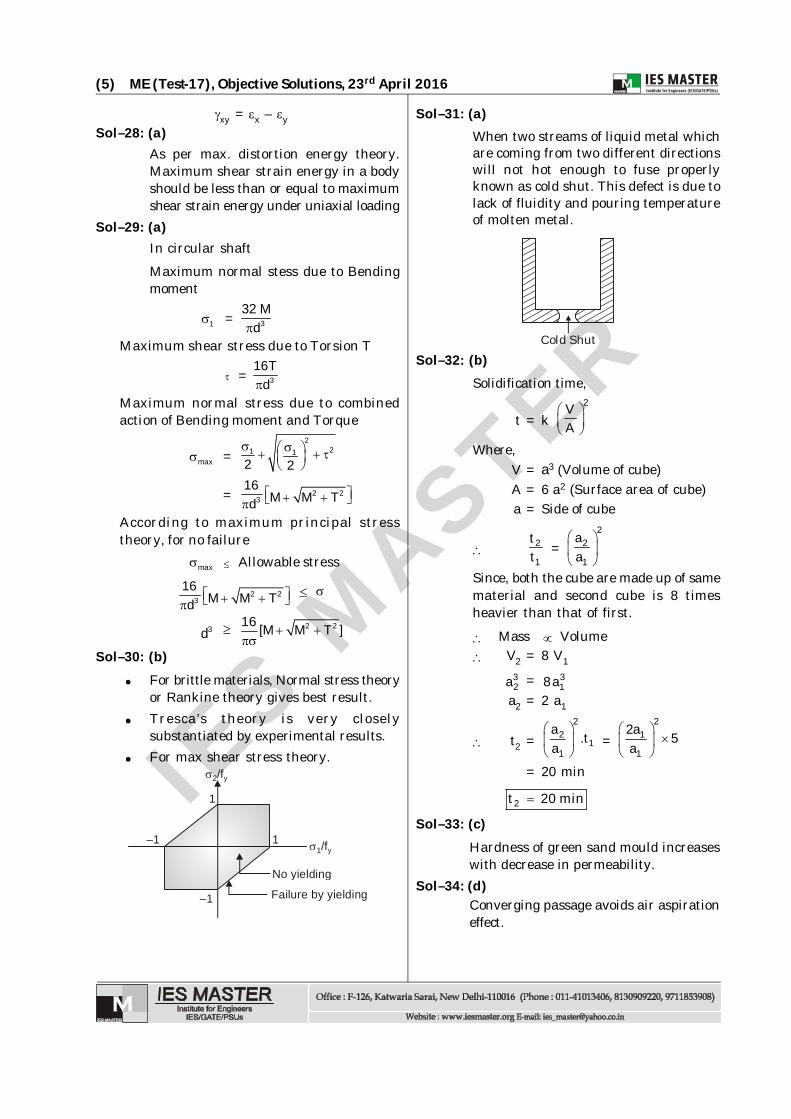
Sol–31: (a)When two streams of liquid metal whichare coming from two different directionswill not hot enough to fuse properlyknown as cold shut. This defect is due tolack of fluidity and pouring temperatureof molten metal.
Cold ShutSol–32: (b)
Solidification time,
t = k 2V
A
Where,V = a3 (Volume of cube)A = 6 a2 (Surface area of cube)a = Side of cube
2
1
tt =
22
1
aa
Since, both the cube are made up of samematerial and second cube is 8 timesheavier than that of first.
Mass Volume V2 = 8 V1
32a = 3
18aa2 = 2 a1
t2 =2
21
1
a .ta
= 2
1
1
2a 5a
= 20 min
2t 20 min
Sol–33: (c)Hardness of green sand mould increaseswith decrease in permeability.
Sol–34: (d)Converging passage avoids air aspirationeffect.

IES M
ASTER
(6) ME (Test-17), Objective Solutions, 23rd April 2016
Sol–35: (d)Martensite is the hardest phase amongthe given structures. fine grains havehigher strength and hardness comparedto coarse grains. Spherodite structure haslower hardness compared to pearlite andmartensite.
Sol–36: (d)Hot chamber die casting is suitable formetals with low melting points
Sol–37: (d)Fluidity is the property of molten metal.
Sol–38: (c)Shell like castings are produced by slushcasting. It is widely used for making toysand decorative parts. Slush casting is usedfor very thin item.
Sol–39: (c)Preheating before welding slows the collingrate of the weld and the base materialand hence prevent cold cracks.
Sol–40: (a)Aluminium Gas Tungsten Arc
weldingDie steel Atomic Hydrogen
weldingCopper Wire SolderingTitanium sheet Laser beam welding
Sol–41: (b)Residual stresses doesn’t depend on thewelding process.
Sol–42: (a)Coining CompressiveWire drawing TensileBlanking ShearDeep drawing Tensil and compressive
Sol–43: (c)Impact extrusion process is used formaking collapsible tubes.
Sol–44: (b)Aluminium is an active metal and it reactswith oxygen in air to produce a thin film ofaluminium oxide on its surface. The melt-ing point of aluminium oxide is almost threetimes that of pure aluminium. In addition,this aluminium oxide film will absorb
moisture from the air which causes poros-ity in the aluminium welds.
Sol–45: (c)By extrusion process, it is possible to makecomponents which have a constant cross-section over any length as can be had bythe rolling process.In the forward hot extrusion, the flow ofmetal is in the forward direction, i.e, thesame as that of the ram. In forwardextrusion, the problem of friction isprevalent because of the relative motionbetween the heated metal billet and thecylinder walls. This is particularly severein the case of steels because of their higherextrusion temperatures. To reduce thisfriction, lubricants are to be used. At lowertemperatures, a mixture of oil and graphiteis generally used. The problem oflubrication gets compounded at the higheroperating temperatures.In order to completely overcome the friction,the backward hot extrusion, is used. In this,the metal is confined fully by the cylinder.The ram which houses the die, alsocompresses the metal against the container,forcing it to flow backwards through thedie in the hollow plunger or ram. It istermed backward because of the oppositedirection of the flow of metal to that of rammovement. Thus, the billet in the containerremains stationary and hence no friction.Also, the extrusion pressure is not affectedby the length of the billet in the extrusionpress since friction is not involved. Thesurface quality achieved is generally goodsince there is no heat cracking due to thefriction between the billet and the extrusioncylinder interface.
Sol–46: (a)Tempering is the process of annealingmartensite at low temperature. Althoughmartensite is strong and wear resistant,it is brittle. Its toughness is low, primailybecause of residual stresses introducingby the transformation. When temperingis carried out at a temperature below200°C, stress relief occurs. The martensitegrains retain their strength, but improvetheir toughness and do not change shape

IES M
ASTER
(7) ME (Test-17), Objective Solutions, 23rd April 2016
on storage.Sol–47: (a)Sol–48: (c)
During the drawing operation, themovement of the blank into the die cavityinduces compressive circumferential (hoop)stresses in the flange, which tend to causethe flange to wrinkle during drawing.Wrinkling can be reduced or eliminated ifa blankholder is kept under the effect of acertain force. In order to improveperformance the magnitude of this force canbe controlled as a function of punch travel.
Sol–49: (c)Extrusion force increases with extrusionratio. Extrusion ratio is defined as the ratioof cross-sectional area of the bullet to thatof the extruded section.The force required for extrusion dependson the strength of the billet material, theextrusion ratio, friction between the bulletand the chamber and die surfaces, andprocess variables, such as the temperatureof the bullet and speed of extrusion.
Extrusion force F = A0k ln 0
f
AA
where A0 and Af are bullet and extrudedproduct areas respectively.
Sol–50: (a)dAA = 2 dVM 1
V
and dAA = 2
2dp 1 Mv
When M < 1,A decreases P decreasesA increases P increases
When M > 1,A decreases P increasesA increases P decreases
Since M < 1, so velocity will increase sincethe cross-sectional area decreases.
Sol–51: (c)Blade speed ratio for maximumdiagram efficiency =
cos2 cos30= = 0.433
2
Sol–52: (b)
675 kW 3425 kW
4
175kW
2T
1s
W1-2 = 175 kWQ2-3 = 675 kWW3-4 = 425 kWQ4–1 = ?
W1-2 + Q2-3 = W3-4 + Q4-1
175 + 675 = 425 + Q4-1
Q4-1 = 175 + 675 –425 = 425 kWSol–53: (c)
The efficiency of ideal regenerativeRankine cycle approaches carnotefficiency.
= 2
1
T 3001 1 0.5 or 50%= =T 600
Sol–54: (c)In a two-row curtis stage,WD1 : WD2 = 3:1It means that three-fourth of the totalwork is done by the steam jets on thefirst row of moving blades and one-fourth of the total work is done on thesecond row of moving blades.
Sol–55: (b)With reduction in pressure, the specificvolume will increase. To accomodatehigher volume, the blade height shouldincrease so that there is more annulararea for expanding fluid.
Sol–56: (b)
DOR = mb
fb mb
hh h
= 9 9 0.45= =
11 9 20

IES M
ASTER
(8) ME (Test-17), Objective Solutions, 23rd April 2016
Sol–57: (c)The purpose of reheating the steam is toincrease specific output, increase efficiencyand thus to reduce specific steamconsumption. For reducing turbine speed,compounding is done.
Sol–58: (d)For 50% reaction turbine,
max =2
22cos
1 cos
whre = nozzle angleSol–59: (d)
From iron carban diagram we can observethat the temperature 740ºC and 1% car-bon lies in Hypoeutectic region which con-tains mixture of Austenite and cementite.
Sol–60: (d)For free vortex flow, V.r = constant V1r1 = V2r2
root radius r1 = 250 mm,Tangential velocity at root radiusv1 = 430 m/s.
Blade height = 100 mm Radius at tip r2 = 250 + 100 = 350mmtangential velocity of steam at tip, v2 = ?
v2 = 1 1
2
v r 430 250r 350 = 307 m/s
Sol–61: (b)Since the gases leave the rotor axially,hence
2wV =0
Power output = 1 2w 1 w 2V u V um
1wV = V1 cos 30° = 600 × cos 30°
= 3600
2u1 = 300 m/s.
30°
V11fV
u1
Power output =
31 600 3002
= 156 kWSol–62: (b)
The expression of thrust for turbojetengine
F = ja V um
Where am air flow rate, Vj – nozzle jetvelocity, u-flight velocity. Hence thrust‘F’ increases if –1. Increase in jet velocity ‘Vj’
2. Increase in mass flow rate a'm '
3. Since after burning in jet engine issimilar to reheat in power cycles. Itis done after turbine and beforenozzle in jet engine. It increasesnozzle jet velocity ‘Vj’.
Sol–63: (b)In turbo prop, 80% of thrust comes frompropeller run by turbine and rest 20%thrust is provided by nozzle jet. So 80%expansion takes place in turbine and20% in nozzle.
Sol–64: (c)Specific speed of the pump,
NS = 3/4N QH
= 3/4
1414 25616
= 2828
Type of pump Specific speedSlow speed radial flow 300 – 900Medium speed radial flow 900 – 1500High speed radial flow 1500 – 2400Mixed flow or screw type 2400 – 5000Axial flow or propeller type 3400 – 15000
Sol–65: (a)We know that efficiency of reaction turbine
% =
1 2w 1 w 2V u V ugH
Where 1wV = Velocity of whirl at inlet
2wV = Velocity of whirl at outlet

IES M
ASTER
(9) ME (Test-17), Objective Solutions, 23rd April 2016
For % maximizes, 2w 2V u should beminimized and max, 2w 2V u should be zero
2w 2V u = 0 [ u2 0)]
2wV = 0It means swirl at outlet must be zero
Sol–66: (a)
Pumps in series operation can be used toincrease the head. Total head developed His the sum of heads developed by individualpumps
H =n
ii 1
H d
Pumps in parallel operation can be usedto increase the flow rate. Total flow rateis the sum of individual volume flow rates.
Sol–67: (b)A centrifugal pump will start deliveringthe liquid only when head developed bythe pump is more than manometric head.
Sol–68: (d)Thoma’s cavitation factor
= a v sH H HH
0.15 = S9 1 H40
Hs = 2 mMaximum suction head or height of runneroutlet above tail race or height of turbine abovethe tail race level = Hs = 2 m
Sol–69: (a)
Draft tube connects the tail race It must be air tight and under all
conditions of operation its lower end mustbe submerged below the level of water inthe tail race.
Sol–70: (d)Theoretical maximum efficiency of peltonwheel
max =1 cos
2
in case of semi circular vanes, = 180° = 180° – 0
max = 1 cos02
= 1
= 100%Sol–71: (b)
A centrifugal pump is capable of highdischarge and low total head. As the headrequired here is 80 m, hence multistagingshould be done in series.
NS = 700 unitsN = 700 r.p.m.Q = 3840 lpm = 64 lpsH = ?
As the unit system of NS is not given, wecan take
Q = 64 lps,
NS = 3/4N QH
700 = 3/4700 64
H H = 16 m Hence no. of centrifugal pumps required = 5.
Sol–72: (b) Runner diameter
d0 = hub diameterdh = tip diameterd0 = 4.0 mdh = 1.6 m
Velocity of flow = 6.0 m/sWhirling Velocity = 10.0 m/s
Angular velocity is same for hub and tip
t h
t = Angular velocity at tip
h = angular velocity at hub
t
t
vd = h
h
vd
t4v 10 25m / s
1.6and flow velocity remains same.
IES M
ASTER
(10) ME (Test-17), Objective Solutions, 23rd April 2016
Sol–73: (c)Nickel and Manganese are Austeniticstablizers
Sol–74: (d)On heat treatment, the resultingstructure will have retained Austenite ifMartensite formation finish temperatureis below room temperature.
Sol–75: (a)
T
s
T =T2 33 2
14
s =s4 3 s =s1 2
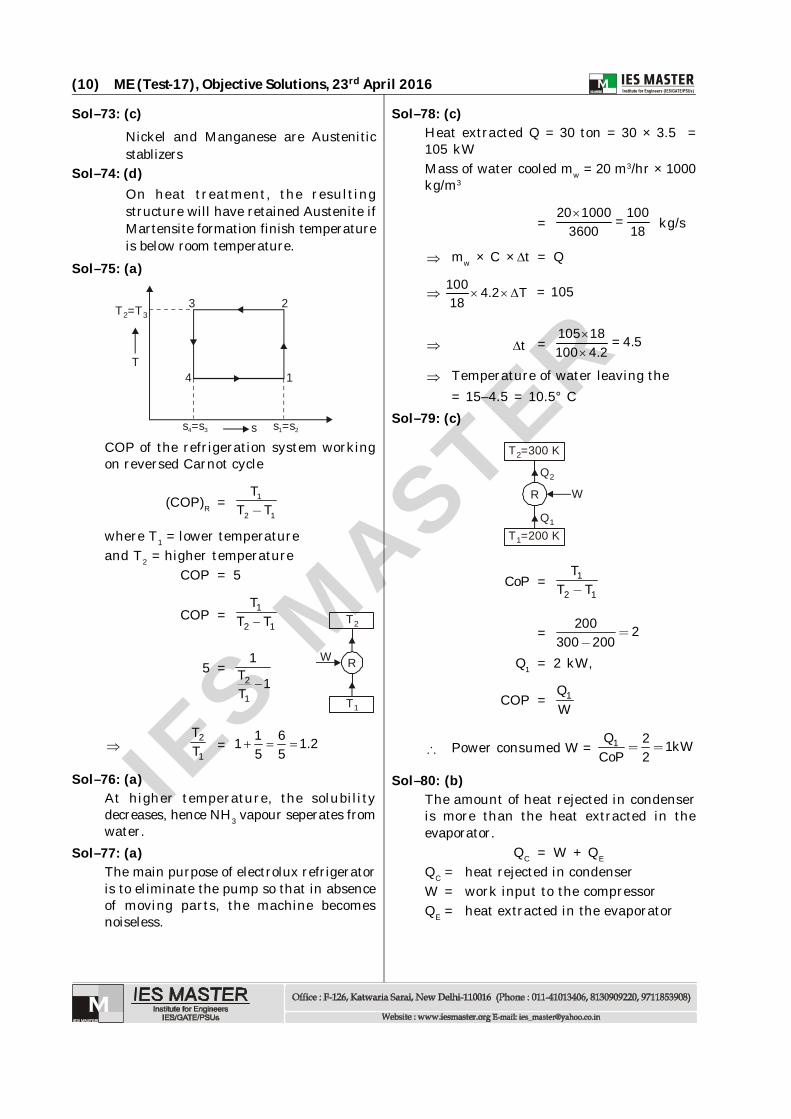
COP of the refrigeration system workingon reversed Carnot cycle
(COP)R = 1
2 1
TT T
where T1 = lower temperatureand T2 = higher temperature
COP = 5
COP = 1
2 1
TT T
5 =2
1
1T 1T
T1
T2
RW
2
1
TT = 1 61 1.2
5 5
Sol–76: (a)At higher temperature, the solubilitydecreases, hence NH3 vapour seperates fromwater.
Sol–77: (a)The main purpose of electrolux refrigeratoris to eliminate the pump so that in absenceof moving parts, the machine becomesnoiseless.
Sol–78: (c)Heat extracted Q = 30 ton = 30 × 3.5 =105 kWMass of water cooled mw = 20 m3/hr × 1000kg/m3
=20 1000 100=
3600 18
kg/s
mw × C × t = Q
100 4.2 T18
= 105
t =105 18 = 4.5100 4.2
Temperature of water leaving the= 15–4.5 = 10.5° C
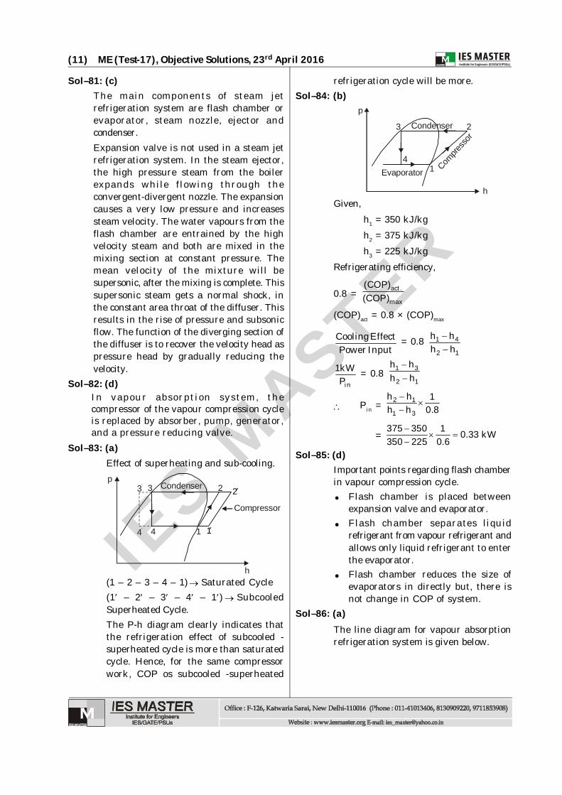
Sol–79: (c)
T2=300 K
T1=200 K
R
Q2
Q1
W
CoP = 1
2 1
TT T
= 200 2300 200
Q1 = 2 kW,
COP = 1QW
Power consumed W = 1Q 2 1kWCoP 2
Sol–80: (b)The amount of heat rejected in condenseris more than the heat extracted in theevaporator.
QC = W + QE
QC = heat rejected in condenserW = work input to the compressorQE = heat extracted in the evaporator
IES M
ASTER
(11) ME (Test-17), Objective Solutions, 23rd April 2016
Sol–81: (c)The main components of steam jetrefrigeration system are flash chamber orevaporator, steam nozzle, ejector andcondenser.Expansion valve is not used in a steam jetrefrigeration system. In the steam ejector,the high pressure steam from the boilerexpands while flowing through theconvergent-divergent nozzle. The expansioncauses a very low pressure and increasessteam velocity. The water vapours from theflash chamber are entrained by the highvelocity steam and both are mixed in themixing section at constant pressure. Themean velocity of the mixture will besupersonic, after the mixing is complete. Thissupersonic steam gets a normal shock, inthe constant area throat of the diffuser. Thisresults in the rise of pressure and subsonicflow. The function of the diverging section ofthe diffuser is to recover the velocity head aspressure head by gradually reducing thevelocity.
Sol–82: (d)In vapour absorption system, thecompressor of the vapour compression cycleis replaced by absorber, pump, generator,and a pressure reducing valve.
Sol–83: (a)Effect of superheating and sub-cooling.
2
Compressor
3
h
pCondenser
4 1
3
4 1
2
(1 – 2 – 3 – 4 – 1) Saturated Cycle(1 – 2 – 3 – 4 – 1) SubcooledSuperheated Cycle.The P-h diagram clearly indicates thatthe refrigeration effect of subcooled -superheated cycle is more than saturatedcycle. Hence, for the same compressorwork, COP os subcooled -superheated
refrigeration cycle will be more.Sol–84: (b)
2
Compre
ssor
3
h
p
Condenser
Evaporator4
1
Given,h1 = 350 kJ/kgh2 = 375 kJ/kgh3 = 225 kJ/kg
Refrigerating efficiency,
0.8 = act.
max
(COP)(COP)
(COP)act = 0.8 × (COP)max
Cooling EffectPowerInput = 0.8
1 4
2 1
h hh h
in
1kWP = 0.8
1 3
2 1
h hh h
Pin =
2 1
1 3
h h 1h h 0.8
=
375 350 1 0.33 kW350 225 0.6
Sol–85: (d)Important points regarding flash chamberin vapour compression cycle. Flash chamber is placed between
expansion valve and evaporator. Flash chamber separates liquid
refrigerant from vapour refrigerant andallows only liquid refrigerant to enterthe evaporator.
Flash chamber reduces the size ofevaporators in directly but, there isnot change in COP of system.
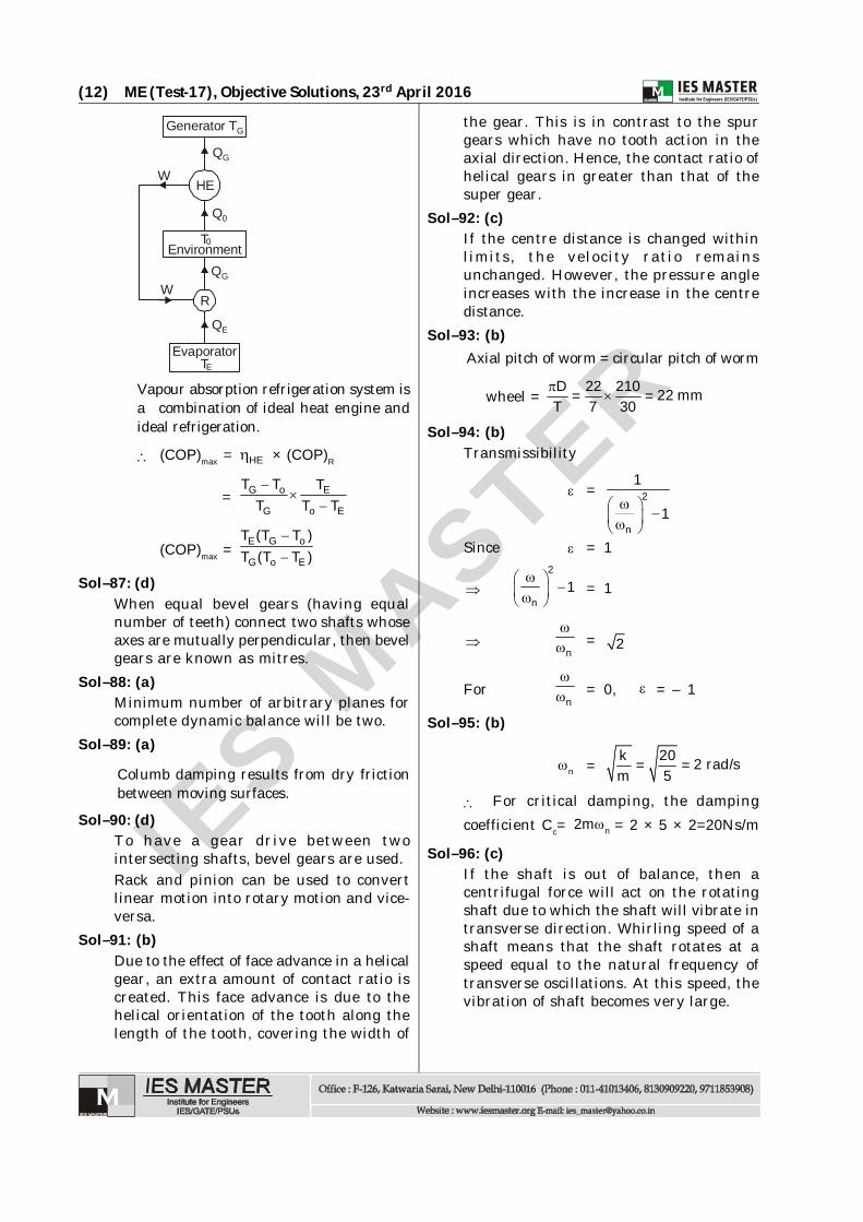
Sol–86: (a)The line diagram for vapour absorptionrefrigeration system is given below.
IES M
ASTER
(12) ME (Test-17), Objective Solutions, 23rd April 2016
QG
Q0
HE
T0
Generator TG
EnvironmentQG
QE
R
TEEvaporator
W
W
Vapour absorption refrigeration system isa combination of ideal heat engine andideal refrigeration.
(COP)max = HE × (COP)R
= G o E
G o E
T T TT T T
(COP)max = E G o
G o E
T (T T )T (T T )
Sol–87: (d)When equal bevel gears (having equalnumber of teeth) connect two shafts whoseaxes are mutually perpendicular, then bevelgears are known as mitres.
Sol–88: (a)Minimum number of arbitrary planes forcomplete dynamic balance will be two.
Sol–89: (a)
Columb damping results from dry frictionbetween moving surfaces.
Sol–90: (d)To have a gear drive between twointersecting shafts, bevel gears are used.Rack and pinion can be used to convertlinear motion into rotary motion and vice-versa.
Sol–91: (b)Due to the effect of face advance in a helicalgear, an extra amount of contact ratio iscreated. This face advance is due to thehelical orientation of the tooth along thelength of the tooth, covering the width of
the gear. This is in contrast to the spurgears which have no tooth action in theaxial direction. Hence, the contact ratio ofhelical gears in greater than that of thesuper gear.
Sol–92: (c)If the centre distance is changed withinlimits, the velocity ratio remainsunchanged. However, the pressure angleincreases with the increase in the centredistance.
Sol–93: (b)Axial pitch of worm = circular pitch of worm
wheel = D 22 210 22 mm= =T 7 30
Sol–94: (b)Transmissibility
=
2
n
1
1
Since = 1
2
n1 = 1
n
= 2
Forn
= 0, = – 1
Sol–95: (b)
n = k 20 2 rad/s= =m 5
For critical damping, the dampingcoefficient Cc= n2m = 2 × 5 × 2=20Ns/m
Sol–96: (c)If the shaft is out of balance, then acentrifugal force will act on the rotatingshaft due to which the shaft will vibrate intransverse direction. Whirling speed of ashaft means that the shaft rotates at aspeed equal to the natural frequency oftransverse oscillations. At this speed, thevibration of shaft becomes very large.

IES M
ASTER
(13) ME (Test-17), Objective Solutions, 23rd April 2016
Sol–97: (a)Module: Ratio of pitch circle diameter inmm to the number of teethAddendum: Radial distance of a tooth fromthe pitch circle to the top of the toothCircular pitch: Distance on the circum-ference of the pitch circle from point of onetooth to the corresponding point on the nexttooth.
Sol–98: (a)
Inertia force
Fi = – F = – 2 cos 2m r cosn
The inertia consists of primary and secondaryunbalanced forces of the reciprocatingmasses. The inertia force acts along the lineof stroke of reciprocating engine, hence theprimary and secondary disturbing forces willbe acting along the line of stroke.
The balancing of primary unbalanced forcecan only be done partially.
Sol–99: (a)The effects of higher pressure angle are-1. Higher pressure angle results in lesser
number teeth to avoid interference.Because
Tmin = 2
2
1 3sin 1
2. Interference and cutter are not prob-lem at higher pressure angle.3. Size of gear depends upon modulewhich have no relation with pressure angle.4. The radial force,
Fr = FsinHence ‘Fr’ will increase with increase inpressure angle. So this is the best optionavailable to avoid pressure angle more than25°.
Sol–100: (b)
Pressure angle = 14.5
Nos. of teeth t = 48
Pitch circle diameter = 28.8 cm1. Module,
m = dt
= 28848
= 6 mm2. Circular pitch,
= dt
= 18.853. Addendum = one module = 6 mm4. Diametral pitch,
= d 48=t 288
= 3/18Sol–101: (a)
Radial engines are balanced by reversecrank method. In three cylinder radialengines having cylinder at 120°, theprimary direct crank and primary reversecrank diagrams are :
F3F2
F1
3 = 2402 = 1201 = 0
1
2 3
Directprimary crank
Magnitude of force of primary and reverse (rank),
F = 2mr2
= F1 = F2 = F3
Force due to direct primary crank,
= F1 + F2 + F3 = 23mr2
Force due to reverse primary crank,

IES M
ASTER
(14) ME (Test-17), Objective Solutions, 23rd April 2016
F1 1 = 0
1
2 3
Reverseprimary crank
F3 F2
2 = 120
3 = 240
F1, F2 and F3 are in balanced condition.So resultant force due to reverse crank iszero,
Fr = 0 Net primary force,
Fd + Fr = 23 mr 02
= 23mr2
Sol–102: (d)
100 N
20 N/cm
The natural frequency
n = k.gk / m =W
where k = 20 N/cmW = 100 N
n will increase if reduces below 100N or ‘k’ increases above 20 N/cm.
Sol–103: (d)The motion equation,
x = 1.25 sin
5t cm
6The standard motion equation,
x = A sin( t + ) cm
A. Amplitude,A = 1.25 cm
B. Frequency (cycle/sec),
= 2 f
f =
5
2 2C. Phase angle,
=
6Time period (sec),
T = 2 sec5
1f
Sol–104: (c)Critical speed of shaft is its naturalangular speed so for simple supportedcase.
n = 348EI k
mml
where k is stiffness of system defined as-
k = 348EI
So critical speed depends upon both massand stiffness.
Sol–105: (a)Tempering Inducing toughnessQuenching HardeningAnnealing SofteningNormalizing Strengthening and
grain refinementSol–106: (d)
Drop wise condensation can be maintainedon new surfaces with promotor e.g., fattyacids. In long run of equipments thesefatty acids are washed away and dropwisecondensation deminshes and filmcondensation runs. The reason for thistransformation is deposition of salts ontube surface. So generally all boiling andcondensing equipments are designed onfilm wise condensation.
Sol–107: (a)If the material is homogeneous & isotropic,magnitude of deformation will be same ifE & µ are same in all direction.

IES M
ASTER
(15) ME (Test-17), Objective Solutions, 23rd April 2016
x =
yx zE E E ... (i)
x = y zx
E E E... (ii)
Magnitude of x in (i) as well as (ii) is same.Sol–108: (d)
(i) Steam flow through nozzle may be sofast that sufficient time is not availablefor heat transfer to take place and sothe phase change lags behind theexpansion. Generally time availablemay be of the order of 10-2 second forsteam to flow through nozzle along withits condensation.
(ii) Also the condensation of steam mayhave inherent requirement of nuclei ofcondensation which act as initiatorsfor condensation. These nuclei ofcondensation may be provided byforegin particles, solid boundary etc.In the absence of nuclei ofcondensation, the phase change ofsteam may get delayed.
The actual discharge from nozzle isslightly greater than the theoreticaldischarge only in the case of supersaturatedflow. In other cases, the actual flow isless than the isentropic flow and the ratiois represented by discharge coefficient.
Sol–109: (d)At lower speed, the rocket is the mostinefficient space engine. It has nothingto do with space condition so rocketvelocity depends upon burning rate in-side it.
Sol–110: (c)Because of high air flow rate throughpropeller, the thrust is higher i.e. higherpower and better propulsive efficiencyas compared to turbojet.The propeller can not be mounted di-rectly on turbine shaft because at highspeed of rotation of turbine, the propel-ler will be damaged because of high cen-trifugal stresses. So a reduction gear isprovided between turbine and propeller.
Sol–111: (c)Comparing discharge head conditions, areciprocating pump is more efficient thana centrifugal pump by 10 – 20 percent.The reason is there is an inherent largeslip loss due to centrifugal loss incentrifugal pump.The discharge from a reciprocating pumpdepends upon its speed as water comesfrom the direct movement of piston.
Sol–112: (d)
T
s
T =T2 33 2
14
s =s4 3 s =s1 2
COP of the refrigeration system workingon reversed Carnot cycle
(COP)R = 1
2 1
TT T
where T1 = lower temperatureand T2 = higher temperatureThus, COP of the reversed Carnot cycledecreases on(i) increasing the higher temperature and(ii) decreasing the lower temperature
Sol–113: (c)(COP)HP = (COP)Ref + 1
The desired effect in heat pump and refrig-eration are different.
Sol–114: (b)An open door refrigerator working in anadiabatic room, absorbs heat (Q2) fromroom and rejects (Q1 = Q2 + W) to room.Since heat absorbed is less than the heatreject (Q2 < Q1). Therefore temperature ofthe room will increase.
Sol–115: (a)Since the critical speed is characteristicof a system and so the natural frequency.But instatical and dynamical balancedsystem (ideal condition), the natural
IES M
ASTER
(16) ME (Test-17), Objective Solutions, 23rd April 2016
frequency is assumed to be zero and periodof oscilation as infinite. So any unbalancedand disturbing force to cause vibration iszero.
Sol–116: (d)Normalized steel will have higher hardnessthan annealed steel due to grain refinementat the surfaces (reason rapid cooling by air).
Sol–117: (b)TIG welding process is not as fast as MIGwelding process as separately a filler rod isadded. However, TIG welding requires askilled operator.
Sol–118: (a)Sol–119: (c)
In the lap joints plates to be joined overlapeach other over a sufficient amount of
riveting while in butt joint the plates arein the same plane and butt against eachother. The longitudinal joint in a boiler shellis usually a butt joint with two cornerplates.This joint is more efficient than lap joint.It is also stiffer to maintain circularity ofshell at ends of the plates.The circumferential joint is a lap joint.Butt joints are more efficient than lapjoints.
Sol–120: (c)Draft angles are necessary in almost all the
forging dies, in order to facilitate theremoval of the part, from the die.