CONTROLS AND DISPLAYS - NASA
5
APOLLO NEWS REFERENCE CONTROLS AND DISPLAYS COR'S CIRCUIT ENGINE THRUST BREAKER PANEL CONTROL RCS CAUTN AND WARNING ECS lHTING lMP'S CIRCUIT BREAKER PANEL ORÞAL EOVE AUD LHTING EAL DEVICES POWER + MAIN PROPULSION � FLIGHT CONTROLS R-42 Control and Display Panels Locator The controls and displays enable astronauts to monitor and manage the LM subsystems and to control the LM manually during separation, docking, and landing. In general, the controls and displays are in sub- systems groupings located in accordance with astronaut responsibilities. Certain controls and displays are duplicated to tisfy mission and/or fety requirements; a system of interlocks prevents simultaneous operation of these controls Controls and displays that enable either astronaut to control the LM are centrally located; these are accessible from both flight stations. Controls that could be operated inadvertently are appropriately guarded. Annunciator displays go on if malfunctions occur in the LM subsystems; at the me time, two flashing master alarm lights and an alarm tone (in the astronaut headsets) are activated. Digital and analog displays provide the astronauts with subsystem-status information such as gas and liquid quantities, pressures, temperatures, and voltages. There are 12 control and display panels. The main control and display panels ( 1 and 2) are canted and centered between the flight stations. Panels 3 and 4 are below these panels, within con- venient reach and scan of both astronauts. Panels 5, 8, and 11 are located for use by the Commander. Panels 6, 12, 14, and 16 are located for use by the LM pilot. Panel 1, directly in view of the Commander, contains various controls and displays, including warning lights, digital counters, navigational instru- ments, engine thrust control switches, and engine, fuel, and altitude indicators. Panel 2, directly in view of the LM Pilot, contains caution lights, reaction control indicators, environmental control indicators, navigational instruments, and various other indicators and switches. Panel 3 contains controls and displays for radar, stabilization and control, heater control, an event timer, and lighting. Panel 4 contains a display and keyboard assembly. The display and keyboard provides a two-way communications link between the CD-1
Transcript of CONTROLS AND DISPLAYS - NASA

APOLLO NEWS REFERENCE
CONTROLS AND DISPLAYS
COR'S CIRCUIT ENGINE THRUST
BREAKER PANEL CONTROL RCS
CAUTION
AND WARNING ECS liGHTING
lMP'S CIRCUIT
BREAKER PANEL
/TI�� ORDEAL EXPlOSIVE AUDIO LIGHTING ELECTlttCAL
DEVICES POWER
1!1111111 MAIN PROPULSION � FLIGHT CONTROLS
R-42
Control and Display Panels Locator
The controls and displays enable astronauts to monitor and manage the LM subsystems and to control the LM manually during separation, docking, and landing.
In general, the controls and displays are in subsystems groupings located in accordance with astronaut responsibilities. Certain controls and displays are duplicated to satisfy mission and/or safety requirements; a system of interlocks prevents simultaneous operation of these controls Controls and displays that enable either astronaut to control the LM are centrally located; these are accessible from both flight stations. Controls that could be operated inadvertently are appropriately guarded.
Annunciator displays go on if malfunctions occur in the LM subsystems; at the same time, two flashing master alarm lights and an alarm tone (in the astronaut headsets) are activated. Digital and analog displays provide the astronauts with subsystem-status information such as gas and liquid quantities, pressures, temperatures, and voltages.
There are 12 control and display panels. The main control and display panels ( 1 and 2) are canted and centered between the flight stations. Panels 3 and 4 are below these panels, within convenient reach and scan of both astronauts. Panels 5, 8, and 11 are located for use by the Commander. Panels 6, 12, 14, and 16 are located for use by the LM pilot.
Panel 1, directly in view of the Commander, contains various controls and displays, including warning lights, digital counters, navigational instru
ments, engine thrust control switches, and engine, fuel, and altitude indicators. Panel 2, directly in view of the LM Pilot, contains caution lights, reaction control indicators, environmental control indicators, navigational instruments, and various other indicators and switches. Panel 3 contains
controls and displays for radar, stabilization and control, heater control, an event timer, and lighting. Panel 4 contains a display and keyboard assembly. The display and keyboard provides a t wo-way communications link between the
CD-1

APOLLO NEWS REFERENCE
astronauts and the LM guidance computer. The panel contains indicator lights, pushbuttons, data displays, and toggle switches. In front of the Commander's and LM Pilot's stations, at waist height, are panels 5 and 6, respectively. Panel 5 contains lighting and mission timer controls, engine start and stop pushbuttons, and an X-translation pushbutton. Abort guidance controls are on panel6.
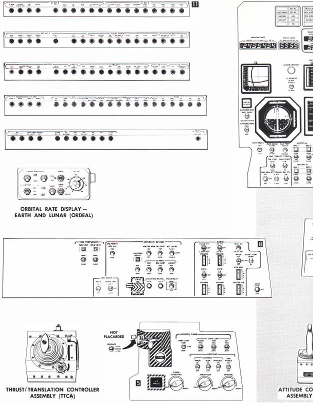
At the left of the Commander's station is panel 8, which is canted up 1 5° from the horizontal. This panel contains controls and displays for explosive devices and descent propulsion, and audio controls. The orbital rate display - earth and lunar (ORDEAL) panel aft and on top of panel 8, is an electromechanical device that provides an alternative to the pitch display of the flight director attitude indicator on panels 1 and 2. When selected, the ORDEAL produces a flight director attitude indicator display of computer local vertical attitude indicator display of computed local vertical attitude during earth or lunar circular orbits. Panel 11, directly above panel 8, has five angled surfaces that contain circuit breakers. Each row of circuit breakers is canted 15° to the line of sight, so that a white band around the circuit breakers is visible when the breakers are open.
At the right of the LM Pilot's station is panel1 2, which is canted up 15° from the horizontal. This panel contains audio, communications, and communications antenna controls and displays. Directly above panel12 is panel14. It is canted up 36.5° from the horizontal and contains controls and displays for electrical power distribution and monitoring. Panel 16, directly above panel 1 4, has four angled surfaces that contain circuit breakers.
CD-2
This makes a white band visible around the circuit breakers when the breakers are open.
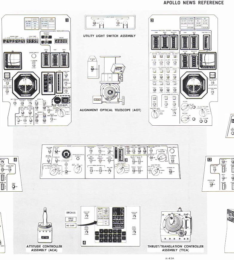
At the right of each flight station is a pistol-grip control (attitude controller assembly), used to control LM attitude changes.
At the left of each flight station is a T-handle control (thrust/translation controller assembly). This assembly, an integrated translation and thrust controller, is used to command vehicle translations by firing thrusters in the Reaction Control Subsystem, and to throttle the descent engine.
An alignment optical telescope is located between and above the flight stations; it is a manually operated, unity-power, periscope-type device. It is used to determine the position of the LM, using a catalog of stars stored in the LM guidance computer and celestial measurements made by the astronauts. A utility light control centered above the flight stations comprises two switches and two portable light fixtures, one for the Commander and one for the LM Pilot.
Environmental Control Subsystem controls are grouped together on the aft bulkhead, behind the LM Pilot. These controls include an oxygen control module, a suit gas diverter, suit flow controls, suit circuit and canister controls, cabin/suit temperature controls, and water management controls. Cabin relief and dump valve controls are located on the forward and overhead hatch. The Environmental Control Subsystem controls enable the astronauts to maintain a habitable environment, decompress and repressurize the cabin, and regulate water flow for drinking, cooling, food preparation, and firefighting.
� ""''·
�· · · .
� 1(\�, .. - , . .. . .. ( 00.0.00_ , -· < •''-- - _,
i i . . .. j .•. 8 i i @ � tJ � •••
ORBITAL RATE DISPLAYEARTH AND LUNAR (ORDEAL)
THRUST/ TRANSLATION CONTROLLER ASSEMBLY (nCA)
-
; -..ooo �-· tvtHt ,_, --------- ------ -
���In
AniTUDE CO ASSEMBLY
APOLLO NEWS REFERENCE
--·-· fYIHII-1
' ........ ,.Of'Ut,M()fot�
UTILITY LIGHT SWITCH ASSEMBLY
--liiiil lilliE!
_ .. ,_, un�<O �··� OKmO� . ��' ,w n•,_ ....... , �· H(;J '
��- .����1�K OMO��:�-®:.. �;.:j ALIGNMENT OPTICAL TELESCOPE (AOT)
'iJ!!J "\!!/ -· _, ........ """' .,.:;; , .. ..__.:. ell\ r�"-::"-··· � - - � e� ® Q 8 \l ... -· , . . ,. _ u- hOM
... o. u
� lDG.O.""
�-- "-tVOIAUoOAI
�:-- ··� ..... � �o· 1 � �- ... _ .... •n•-� €) ... ,. ,.ow
. � .. �·�·-"'"" "® ( •. ::.�:::.:...] ·!-�.:. ··0-·
ATTITUDE CONTROLLER ASSEMBLY (ACA)
.... � "'lllf-- -� "f F"� � - 'fi:-if�1 �-=:l 0 r.;;-··-:-:--::> I , ....... , -- I@ .,.. 1f.:.. 1}.:.. 1}:. i) "".::.'-'"':::.·� �-- - @'
N N N U--·� s €} oO-o
_,....... c�·�::.:.§] - -· --· .. r::: --, -�.. ..
.. .. ..... , -�.--· ·-·
@··-·@·"-� .:::· 8�@� = ·- @-::::: :..':! -.;- -� · -· - ""'@.' "".::'� - - - ....., -.. - - TU<•
THRUST/TRANSLATION CONTROLLER ASSEMBLY (TTCA)
R-43A
r::::::1 a=J .AIIIU-
,.�,,
�- �
�� iffi; ·o

WS REFERENCE
]
NTROLLER
_ ... i.:�•1<oo..• ... _ . .. . __ � ... n�r �"""\ •• i i i • i ••• i i i
- ·-· -·-
Lunar Module Controls and Displays
ATTITUDE CONTROLLER ASSEMBLY (ACA)
j
GRUMMAN CD-3 ,