Controls and Accessories
32
Controls and Accessories Section F
Transcript of Controls and Accessories
Controls and AccessoriesSection F
CCI Thermal Technologies Inc.F2 F3Caloritech™ Index
ContentsControls & Accessories
AR ...............................................................................................................................................................F9High Temperature Wires, Flow & Air Flow Switches ................................................................................. F26Level Probes .............................................................................................................................................F27SCR’s .......................................................................................................................................................F24Specific Purpose Thermostats .................................................................................................................. F18Thermocouple Wells ................................................................................................................................. F22Thermostat Accessories ........................................................................................................................... F10
Electronic Indicating ControlsSeries 100 ................................................................................................................................................F21UT .............................................................................................................................................................F19
Explosion-Proof HousingsXH ...............................................................................................................................................................F6
Explosion-Proof ThermostatXT ............................................................................................................................................................. F11
Fenwal Thermoswitch®
Modifications & Thermostat Wells ............................................................................................................ F14Series 2000 ..............................................................................................................................................F15Series XTF & Percentage Timers ............................................................................................................ F17Snap-Disc Thermostats & Detect-a-Fire® Units ........................................................................................ F16Temperature Controls ............................................................................................................................... F13
ReferenceCatalogues at a Glance .............................................................................................................................. F4Locations ....................................................................................................................................................F3Warranty ...................................................................................................................................................F31
Step ControlsElectronic, Base Load, R851B & Series 566 ............................................................................................ F23
Reference
Edmonton, Alberta Houston, Texas
Orillia, Ontario Oakville, Ontario
Denver, Colorado
As a leader in heating and filtration solutions, CCI Thermal Technologies Inc. is committed to ongoing research, product development and above all, excellence in customer service. With facilities across North America, CCI Thermal manufactures seven of the top brands in industrial heating in addition to a comprehensive line of engineered industrial filtration products including:
Cata-Dyne™ Explosion-Proof Gas Catalytic HeatersRuffneck™ Heaters for the Harshest EnvironmentsCaloritech™ Engineered Electric Heat3L Filters™ Engineered Filtration Systems
Norseman™ Electric Explosion-Proof HeatersDriQuik™ Infrared Oven ComponentsFastrax® Track and Switch Heaters

CCI Thermal Technologies Inc.F2 F3Locations
Edmonton, Alberta Houston, Texas
Orillia, Ontario Oakville, Ontario
Denver, Colorado
As a leader in heating and filtration solutions, CCI Thermal Technologies Inc. is committed to ongoing research, product development and above all, excellence in customer service. With facilities across North America, CCI Thermal manufactures seven of the top brands in industrial heating in addition to a comprehensive line of engineered industrial filtration products including:
Cata-Dyne™ Explosion-Proof Gas Catalytic HeatersRuffneck™ Heaters for the Harshest EnvironmentsCaloritech™ Engineered Electric Heat3L Filters™ Engineered Filtration Systems
Norseman™ Electric Explosion-Proof HeatersDriQuik™ Infrared Oven ComponentsFastrax® Track and Switch Heaters
Caloritech™ electric heaters, heating elements and heating accessories are well-known in the industry for their quality, reliability, performance and versatility. In addition to standard “off the shelf” industrial heaters and heating systems components, Caloritech™ also offers engineered heating solutions custom designed, manufactured and tested to satisfy customer specifications. No matter what your application or environment, Caloritech™ has a solution to fit your heating needs.
We invite you to visit www.ccithermal.com to view the broad range of innovative industrial heating products manufactured by CCI Thermal Technologies Inc.
CCI Thermal Technologies Inc.F4 F5Caloritech™ Catalogues at a Glance
®C US
®
ISO 9001
®C US
®
ISO 9001
Caloritech™ Catalog: Section AElements and Specialty Heaters
Calvane™ heaters, tubular heaters, bolt heaters, tubular band heaters, mitosis heaters, finned tubular heaters, cartridge heaters, strip and finned strip heaters, hot plate/drum heaters, cast-in heaters, transit heaters.
Elements and Specialty Heaters
Section A
Caloritech™ Catalog: Section BImmersion Heaters
screwplug heaters, domestic immersion heaters, urn heaters, flange heaters, over-the-side heaters, pipe insert heaters, gate and gain heaters.
Immersion Heaters Section B
Caloritech™ Catalog: Section CAir and Space Heaters
infrared radiant heaters, panel heaters, convection heaters, commercial and explosion-proof duct heaters, unit heaters, gate and gain heaters.
Air and Space HeatersSection C
Caloritech™ Catalog: Section DEngineered Products
circulation heaters, heat transfer systems, custom engineered products, panel heaters, control panels, technical data.
Engineered ProductsSection D
Caloritech™ Catalog: Section EBoilers
hot water boilers, steam boilers, condensate receiver packages, blow off tanks, packaged circulation heaters, calorifiers.
Boilers Section E
Caloritech™ Catalog: Section FControls
electronic controls, industrial thermostats, explosion-proof thermostats, thermoswitches, thermocouples and thermowells, x-Max® explosion-proof housings.
Controls Section F
Cata-Dyne™ Catalog
explosion-proof infrared gas catalytic heaters, high temperature industrial infrared heaters, infrared gas catalytic heating systems, accessories.
Explosion-Proof Gas Catalytic Heaters
Ruffneck™ Catalog
explosion-proof electric air heaters, heat-exchanger unit heaters, corrosion-resistant washdown unit heaters, convection heaters, thermostats.
Explosion-Proof ElectricAir Heaters
3L Filters™ Catalog
filters, strainers, separators, dehydrators, fuel monitors, clay treaters, head lifts, closures, pressure vessels, engineered products, nuclear, aviation general industrial products.
Norseman™ Catalog
natural convection explosion-proof heaters, forced air explosion-proof heaters, thermostats.
Electric Explosion-Proof
Heaters & Thermostats
Fastrax® Catalog
track and switch heaters, custom designed automated control systems, accessories.
Heaters for the Rail Industry
DriQuik™ Catalog
long, medium and short wavelength infrared oven components and control panels.
CCI Thermal Technologies Inc.
Putting Safety First
CCI Thermal Technologies Inc. has always been committed to the safety and well being of our customers. We are familiar with the safety regulations of heating products in a wide variety of environments and ensure that our products meet or exceed the requirements for their applications. CCI Thermal Technologies Inc. takes great pride in its lines of certifi ed products.
Visit us at www.ccithermal.com
Our website offers on-line PDF catalogs, product specifi cations, installation manuals, and technical documentation 24 hours a day. Additionally, you will fi nd easy access to anyone of our factory representatives, regional sales managers or customer service personnel.
Quality
All our business processes are steered by the principles of ISO 9001 and ASME, providing an operational framework that places emphasis on continual improvement and customer satisfaction.
CCI Thermal Technologies Inc.F4 F5Catalogues at a Glance
Cata-Dyne™ Catalog
explosion-proof infrared gas catalytic heaters, high temperature industrial infrared heaters, infrared gas catalytic heating systems, accessories.
Explosion-Proof Gas Catalytic Heaters
Ruffneck™ Catalog
explosion-proof electric air heaters, heat-exchanger unit heaters, corrosion-resistant washdown unit heaters, convection heaters, thermostats.
Explosion-Proof ElectricAir Heaters
3L Filters™ Catalog
filters, strainers, separators, dehydrators, fuel monitors, clay treaters, head lifts, closures, pressure vessels, engineered products, nuclear, aviation general industrial products.
Norseman™ Catalog
natural convection explosion-proof heaters, forced air explosion-proof heaters, thermostats.
Electric Explosion-Proof
Heaters & Thermostats
Fastrax® Catalog
track and switch heaters, custom designed automated control systems, accessories.
Heaters for the Rail Industry
DriQuik™ Catalog
long, medium and short wavelength infrared ovens and emitters, dusters, cooling tunnels, control panels.
CCI Thermal Technologies Inc.
Putting Safety First
CCI Thermal Technologies Inc. has always been committed to the safety and well being of our customers. We are familiar with the safety regulations of heating products in a wide variety of environments and ensure that our products meet or exceed the requirements for their applications. CCI Thermal Technologies Inc. takes great pride in its lines of certified products.
Visit us at www.ccithermal.com
Our website offers on-line PDF catalogs, product specifications, installation manuals, and technical documentation 24 hours a day. Additionally, you will find easy access to anyone of our factory representatives, regional sales managers or customer service personnel.
Quality
All our business processes are steered by the principles of ISO 9001 and ASME, providing an operational framework that places emphasis on continual improvement and customer satisfaction.
CCI Thermal Technologies Inc.F6 F7Caloritech™
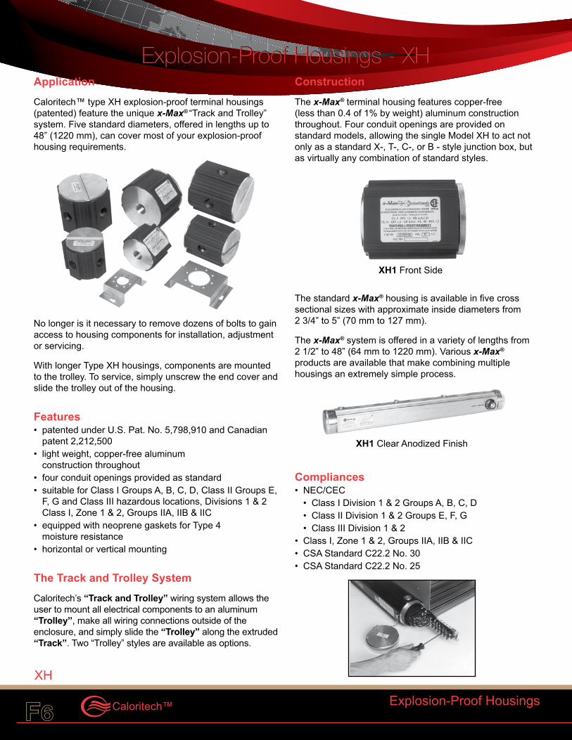
ApplicationCaloritech™ type XH explosion-proof terminal housings (patented) feature the unique x-Max® “Track and Trolley” system. Five standard diameters, offered in lengths up to 48” (1220 mm), can cover most of your explosion-proof housing requirements.
No longer is it necessary to remove dozens of bolts to gain access to housing components for installation, adjustment or servicing.
With longer Type XH housings, components are mounted to the trolley. To service, simply unscrew the end cover and slide the trolley out of the housing.
Features• patented under U.S. Pat. No. 5,798,910 and Canadian
patent 2,212,500• light weight, copper-free aluminum
construction throughout• four conduit openings provided as standard • suitable for Class I Groups A, B, C, D, Class II Groups E,
F, G and Class III hazardous locations, Divisions 1 & 2 Class I, Zone 1 & 2, Groups IIA, IIB & IIC
• equipped with neoprene gaskets for Type 4 moisture resistance
• horizontal or vertical mounting
The Track and Trolley SystemCaloritech’s “Track and Trolley” wiring system allows the user to mount all electrical components to an aluminum “Trolley”, make all wiring connections outside of the enclosure, and simply slide the “Trolley” along the extruded “Track”. Two “Trolley” styles are available as options.
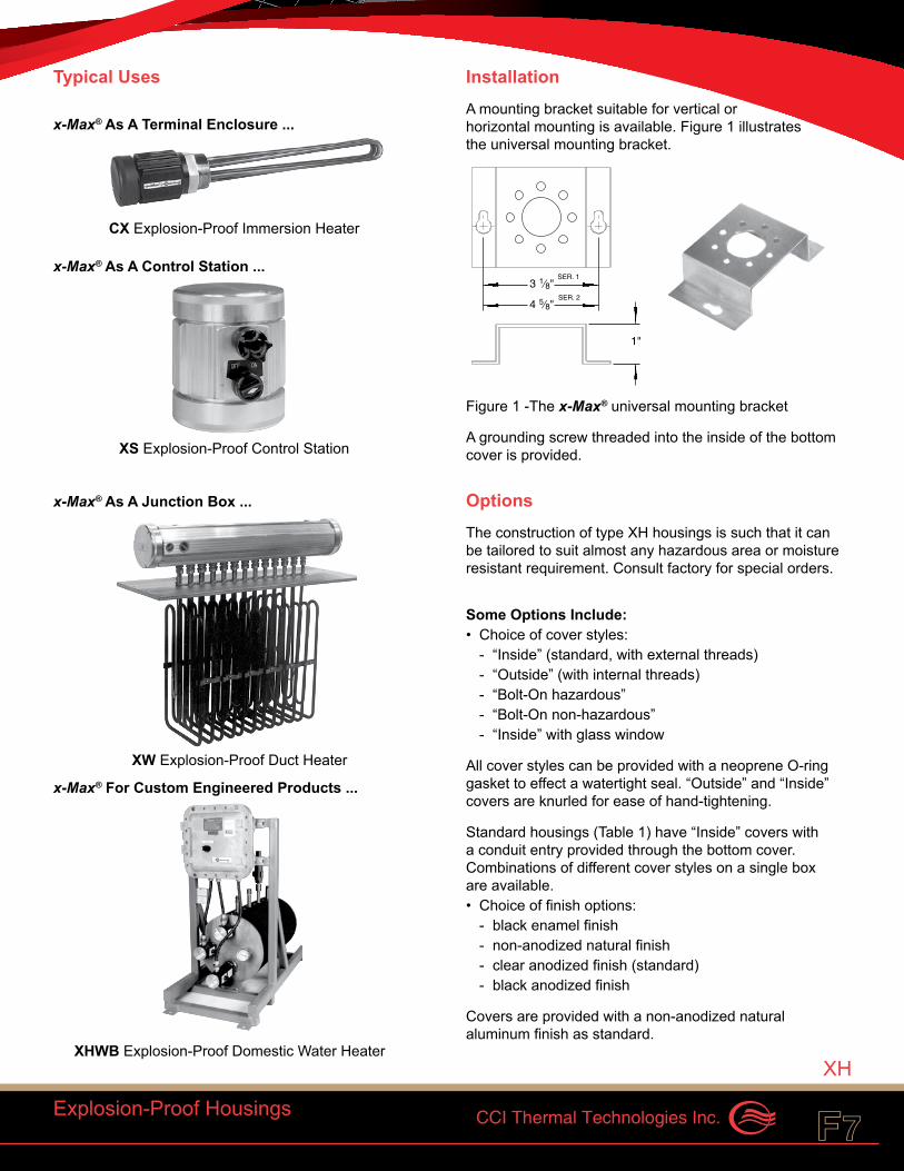
ConstructionThe x-Max® terminal housing features copper-free (less than 0.4 of 1% by weight) aluminum construction throughout. Four conduit openings are provided on standard models, allowing the single Model XH to act not only as a standard X-, T-, C-, or B - style junction box, but as virtually any combination of standard styles.
The standard x-Max® housing is available in five cross sectional sizes with approximate inside diameters from 2 3/4” to 5” (70 mm to 127 mm).
The x-Max® system is offered in a variety of lengths from 2 1/2” to 48” (64 mm to 1220 mm). Various x-Max® products are available that make combining multiple housings an extremely simple process.
Compliances• NEC/CEC
• Class I Division 1 & 2 Groups A, B, C, D• Class II Division 1 & 2 Groups E, F, G• Class III Division 1 & 2
• Class I, Zone 1 & 2, Groups IIA, IIB & IIC• CSA Standard C22.2 No. 30• CSA Standard C22.2 No. 25
Explosion-Proof Housings - XHExplosion-Proof Housings - XH
Explosion-Proof Housings
XH
XH
XH1 Front Side
XH1 Clear Anodized Finish
CCI Thermal Technologies Inc.F6 F7
Typical Uses
x-Max® As A Terminal Enclosure ...
x-Max® As A Control Station ...
x-Max® As A Junction Box ...
x-Max® For Custom Engineered Products ...
InstallationA mounting bracket suitable for vertical or horizontal mounting is available. Figure 1 illustrates the universal mounting bracket.
Figure 1 -The x-Max® universal mounting bracket
A grounding screw threaded into the inside of the bottom cover is provided.
OptionsThe construction of type XH housings is such that it can be tailored to suit almost any hazardous area or moisture resistant requirement. Consult factory for special orders.
Some Options Include:• Choice of cover styles:
- “Inside” (standard, with external threads)- “Outside” (with internal threads)- “Bolt-On hazardous” - “Bolt-On non-hazardous”- “Inside” with glass window
All cover styles can be provided with a neoprene O-ring gasket to effect a watertight seal. “Outside” and “Inside” covers are knurled for ease of hand-tightening.
Standard housings (Table 1) have “Inside” covers with a conduit entry provided through the bottom cover. Combinations of different cover styles on a single box are available.• Choice of finish options:
- black enamel finish- non-anodized natural finish- clear anodized finish (standard)- black anodized finish
Covers are provided with a non-anodized natural aluminum finish as standard.
Explosion-Proof Housings
XH
SER. 13 1⁄8"
1"
SER. 24 5⁄8"
CX Explosion-Proof Immersion Heater
XS Explosion-Proof Control Station
XW Explosion-Proof Duct Heater
XHWB Explosion-Proof Domestic Water Heater
CCI Thermal Technologies Inc.F8 F9Caloritech™
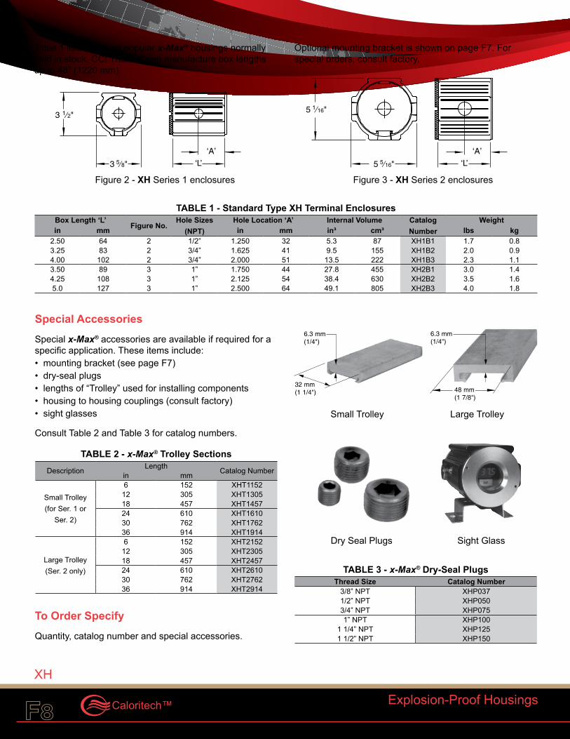
Table 1 lists the most popular x-Max® housings normally held in stock. CCI Thermal can manufacture box lengths up to 48” (1220 mm).
Optional mounting bracket is shown on page F7. For special orders, consult factory.
Explosion-Proof Housings
XH
3 1⁄2"5 1⁄16"
5 5⁄16"
‘A’ ‘A’‘L’3 5⁄8" ‘L’
TABLE 1 - Standard Type XH Terminal Enclosures Box Length ‘L’
Figure No.Hole Sizes
(NPT)Hole Location ‘A’ Internal Volume Catalog
NumberWeight
in mm in mm in³ cm³ lbs kg2.50 64 2 1/2” 1.250 32 5.3 87 XH1B1 1.7 0.83.25 83 2 3/4” 1.625 41 9.5 155 XH1B2 2.0 0.94.00 102 2 3/4” 2.000 51 13.5 222 XH1B3 2.3 1.13.50 89 3 1” 1.750 44 27.8 455 XH2B1 3.0 1.44.25 108 3 1” 2.125 54 38.4 630 XH2B2 3.5 1.65.0 127 3 1” 2.500 64 49.1 805 XH2B3 4.0 1.8
Special AccessoriesSpecial x-Max® accessories are available if required for a specific application. These items include:• mounting bracket (see page F7)• dry-seal plugs• lengths of “Trolley” used for installing components• housing to housing couplings (consult factory)• sight glasses
Consult Table 2 and Table 3 for catalog numbers.
TABLE 2 - x-Max® Trolley Sections Description Length Catalog Numberin mm
Small Trolley (for Ser. 1 or
Ser. 2)
6 152 XHT115212 305 XHT130518 457 XHT145724 610 XHT161030 762 XHT176236 914 XHT1914
Large Trolley (Ser. 2 only)
6 152 XHT215212 305 XHT230518 457 XHT245724 610 XHT261030 762 XHT276236 914 XHT2914
To Order SpecifyQuantity, catalog number and special accessories.
TABLE 3 - x-Max® Dry-Seal Plugs Thread Size Catalog Number
3/8” NPT XHP0371/2” NPT XHP0503/4” NPT XHP0751” NPT XHP100
1 1/4” NPT XHP1251 1/2” NPT XHP150
32 mm(1 1/4")
6.3 mm(1/4")
48 mm(1 7/8")
6.3 mm(1/4")
Small Trolley Large Trolley
Dry Seal Plugs Sight Glass
Figure 2 - XH Series 1 enclosures Figure 3 - XH Series 2 enclosures
3 1⁄2"5 1⁄16"
5 5⁄16"
‘A’ ‘A’‘L’3 5⁄8" ‘L’
CCI Thermal Technologies Inc.F8 F9
Controls & Accessories - AR
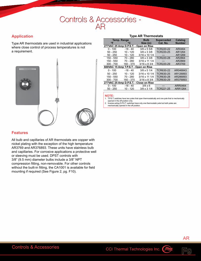
ApplicationType AR thermostats are used in industrial applications where close control of process temperatures is not a requirement.
FeaturesAll bulb and capillaries of AR thermostats are copper with nickel plating with the exception of the high temperature AR3769 and AR376893. These units have stainless bulb and capillaries. For corrosive applications a protective well or sleeving must be used. DPST controls with 3/8” (9.5 mm) diameter bulbs include a 3/8” NPT compression fitting, non-removable. For other controls without the built-in fitting, the CA1001 is available for field mounting if required (See Figure 2, pg. F10).
Type AR Thermostats Temp. Range Bulb Superceded Catalog
°F °C Size (in) Cat. No. Number277VAC 25 Amp D.P.S.T. - Open on Rise
0 - 100 -18 - 40 3/8 x 5 5/8 TCR220-22 AR046450 - 250 10 - 120 3/8 x 3 3/8 TCR220-25 AR126450 - 250 10 - 120 3/16 x 10 1/4 — AR1269150 - 550 70 - 280 3/8 x 3 3/8 TCR220-28 AR2864150 - 550 70 - 280 3/16 x 11 1/4 — AR2869300 - 700 160 - 370 3/16 x 8 3/4 TCR220-29 AR3769
600VAC 15 Amp T.P.S.T - Open on Rise0 - 100 -18 - 40 3/8 x 5 1/4 TCR630-22 AR046843
50 - 250 10 - 120 3/16 x 10 1/4 TCR630-25 AR126893150 - 550 70 - 280 3/16 x 11 1/4 TCR630-28 AR286893300 - 700 160 - 370 3/16 x 8 3/4 TCR630-29 AR376893
277VAC 25 Amp D.P.S.T. - Close on Rise0 - 100 -18 - 40 3/8 x 6 — ARR046450 - 250 10 - 120 3/8 x 3 1/4 TCR221-25 ARR1264
NOTE:1. T.P.S.T. switches have two poles that open thermostatically and one pole that is mechanically
opened in the off position only.2. Inverse acting D.P.S.T. switches have only one thermostatic pole but both poles are
mechanically opened in the off position.
Controls & Accessories
AR
Controls & Accessories - AR
CCI Thermal Technologies Inc.F10 F11Caloritech™
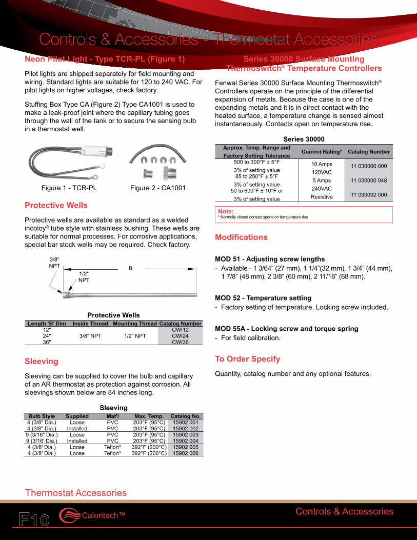
Neon Pilot Light - Type TCR-PL (Figure 1) Pilot lights are shipped separately for field mounting and wiring. Standard lights are suitable for 120 to 240 VAC. For pilot lights on higher voltages, check factory.
Stuffing Box Type CA (Figure 2) Type CA1001 is used to make a leak-proof joint where the capillary tubing goes through the wall of the tank or to secure the sensing bulb in a thermostat well.
Protective WellsProtective wells are available as standard as a welded incoloy® tube style with stainless bushing. These wells are suitable for normal processes. For corrosive applications, special bar stock wells may be required. Check factory.
Protective Wells Length ‘B’ Dim Inside Thread Mounting Thread Catalog Number
12"3/8” NPT 1/2" NPT
CWI1224" CWI2436" CWI36
SleevingSleeving can be supplied to cover the bulb and capillary of an AR thermostat as protection against corrosion. All sleevings shown below are 84 inches long.
Sleeving Bulb Style Supplied Mat'l Max. Temp. Catalog No.4 (3/8" Dia.) Loose PVC 203°F (95°C) 15902 0014 (3/8" Dia.) Installed PVC 203°F (95°C) 15902 0029 (3/16" Dia.) Loose PVC 203°F (95°C) 15902 0039 (3/16' Dia.) Installed PVC 203°F (95°C) 15902 0044 (3/8' Dia.) Loose Teflon® 392°F (200°C) 15902 0054 (3/8' Dia.) Loose Teflon® 392°F (200°C) 15902 006
Series 30000 Surface Mounting Thermoswitch® Temperature Controllers
Fenwal Series 30000 Surface Mounting Thermoswitch® Controllers operate on the principle of the differential expansion of metals. Because the case is one of the expanding metals and it is in direct contact with the heated surface, a temperature change is sensed almost instantaneously. Contacts open on temperature rise.
Series 30000 Approx. Temp. Range and Factory Setting Tolerance
Current Rating* Catalog Number
500 to 300°F ± 5°F 3% of setting value
10 Amps 120VAC 5 Amps 240VAC Resistive
11 030000 000
85 to 250°F ± 5°F 3% of setting value
11 030000 048
50 to 600°F ± 10°F or 3% of setting value
11 030002 000
Note:* Normally closed contact opens on temperature rise
Modifications
MOD 51 - Adjusting screw lengths- Available - 1 3/64” (27 mm), 1 1/4”(32 mm), 1 3/4” (44 mm),
1 7/8” (48 mm), 2 3/8” (60 mm), 2 11/16” (68 mm).
MOD 52 - Temperature setting- Factory setting of temperature. Locking screw included.
MOD 55A - Locking screw and torque spring- For field calibration.
To Order SpecifyQuantity, catalog number and any optional features.
Controls & Accessories
Controls & Accessories - Thermostat Accessories
Thermostat Accessories
Controls & Accessories - Thermostat Accessories
1/2"NPT
3/8"NPT B
Thermostat Accessories
Figure 1 - TCR-PL Figure 2 - CA1001
CCI Thermal Technologies Inc.F10 F11
ApplicationThe Model XT explosion-proof thermostat utilizes the unique x-Max® system (U.S. Pat. No. 5,798,910, CDN Pat.No. 2,212,500) to provide maximum durability, safety and ease of use. Three basic units are available to suit most hazardous location temperature control applications.
XT thermostats are suitable for air, duct, pipe or tank temperature control.
Features• approvals for all area classifications• value engineered• remote or local temperature sensing• ratings to 600V, S.P.S.T. and D.P.S.T.• multiple conduit entries• externally adjustable with tamper-proof feature• O-rings for moisture protection
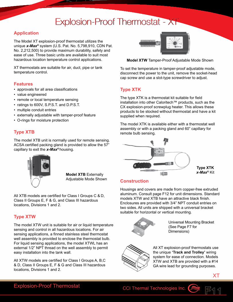
Type XTBThe model XTB unit is normally used for remote sensing. ACSA certified packing gland is provided to allow the 57” capillary to exit the x-Max® housing.
All XTB models are certified for Class I Groups C & D, Class II Groups E, F & G, and Class III hazardous locations, Divisions 1 and 2.
Type XTWThe model XTW unit is suitable for air or liquid temperature sensing and control in all hazardous locations. For air sensing applications, a finned stainless steel thermostat well assembly is provided to enclose the thermostat bulb. For liquid sensing applications, the model XTWL has an external 1/2” NPT thread on the well assembly to permit easy installation into the tank wall.
All XTW models are certified for Class I Groups A, B,C & D, Class II Groups E, F & G and Class III hazardous locations, Divisions 1 and 2.
To set the temperature in tamper-proof adjustable mode, disconnect the power to the unit, remove the socket-head cap screw and use a slot-type screwdriver to adjust.
Type XTKThe type XTK is a thermostat kit suitable for field installation into other Caloritech™ products, such as the CX explosion-proof screwplug heater. This allows these products to be stocked without thermostat and have a kit supplied when required.
The model XTK is available either with a thermostat well assembly or with a packing gland and 60” capillary for remote bulb sensing.
ConstructionHousings and covers are made from copper-free extruded aluminum. Consult page F12 for unit dimensions. Standard models XTW and XTB have an attractive black finish. Enclosures are provided with 3/4” NPT conduit entries on two sides. All units are shipped with a universal bracket suitable for horizontal or vertical mounting.
All XT explosion-proof thermostats use the unique ‘Track and Trolley’ wiring system for ease of connection. Models XTW and XTB are provided with a #14 GA wire lead for grounding purposes.
Explosion-Proof Thermostat - XTExplosion-Proof Thermostat - XT
Explosion-Proof Thermostat
XT
Model XTW Tamper-Proof Adjustable Mode Shown
Model XTB Externally Adjustable Mode Shown
Type XTK x-Max® Kit
Universal Mounting Bracket (See Page F7 for Dimensions)
CCI Thermal Technologies Inc.F12 F13Caloritech™
1⁄2" N.P.T.
L
3 1⁄2"(90 mm)
57"(1450 mm)
12 1⁄2"(318 mm)
3 5⁄8"(92 mm)
Type XTWL
Type XTWA
Type XTB
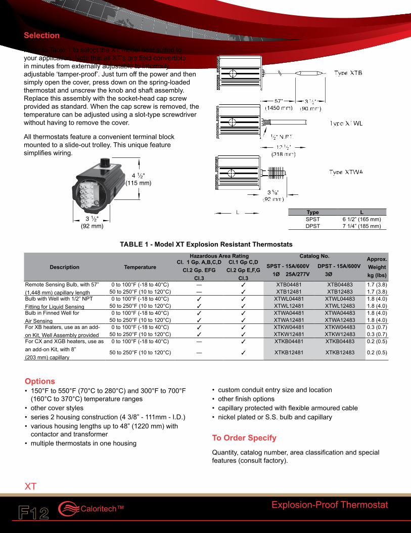
SelectionRefer to Table 1 to select the XT model best suited to your application. Note that all XT’s are field convertible in minutes from externally adjustable to internally adjustable ‘tamper-proof’. Just turn off the power and then simply open the cover, press down on the spring-loaded thermostat and unscrew the knob and shaft assembly. Replace this assembly with the socket-head cap screw provided as standard. When the cap screw is removed, the temperature can be adjusted using a slot-type screwdriver without having to remove the cover.
All thermostats feature a convenient terminal block mounted to a slide-out trolley. This unique feature simplifies wiring.
Explosion-Proof Thermostat
XT
3 1⁄2"(92 mm)
4 1⁄2"(115 mm)
Type LSPST 6 1/2” (165 mm)DPST 7 1/4” (185 mm)
Options• 150°F to 550°F (70°C to 280°C) and 300°F to 700°F
(160°C to 370°C) temperature ranges• other cover styles• series 2 housing construction (4 3/8” - 111mm - I.D.)• various housing lengths up to 48” (1220 mm) with
contactor and transformer• multiple thermostats in one housing
• custom conduit entry size and location• other finish options• capillary protected with flexible armoured cable• nickel plated or S.S. bulb and capillary
To Order SpecifyQuantity, catalog number, area classification and special features (consult factory).
TABLE 1 - Model XT Explosion Resistant Thermostats
Description Temperature
Hazardous Area Rating Catalog No. Approx. Weight kg (lbs)
Cl. 1 Gp. A,B,C,D Cl.2 Gp. EFG
Cl.3
Cl.1 Gp C,D Cl.2 Gp E,F,G
Cl.3
SPST - 15A/600V 1Ø 25A/277V
DPST - 15A/600V 3Ø
Remote Sensing Bulb, with 57” (1,448 mm) capillary length
0 to 100°F (-18 to 40°C) — 3 XTB04481 XTB04483 1.7 (3.8)50 to 250°F (10 to 120°C) — 3 XTB12481 XTB12483 1.7 (3.8)
Bulb with Well with 1/2” NPT Fitting for Liquid Sensing
0 to 100°F (-18 to 40°C) 3 3 XTWL04481 XTWL04483 1.8 (4.0)50 to 250°F (10 to 120°C) 3 3 XTWL12481 XTWL12483 1.8 (4.0)
Bulb in Finned Well for Air Sensing
0 to 100°F (-18 to 40°C) 3 3 XTWA04481 XTWA04483 1.8 (4.0)50 to 250°F (10 to 120°C) 3 3 XTWA12481 XTWA12483 1.8 (4.0)
For XB heaters, use as an add-on Kit, Well Assembly provided
0 to 100°F (-18 to 40°C) 3 3 XTKW04481 XTKW04483 0.3 (0.7)50 to 250°F (10 to 120°C) 3 3 XTKW12481 XTKW12483 0.3 (0.7)
For CX and XGB heaters, use as an add-on Kit, with 8” (203 mm) capillary
0 to 100°F (-18 to 40°C) — 3 XTKB04481 XTKB04483 0.2 (0.5)
50 to 250°F (10 to 120°C) — 3 XTKB12481 XTKB12483 0.2 (0.5)
CCI Thermal Technologies Inc.F12 F13
To Order SpecifyQuantity, catalog number, and any special features (see pg. F14).
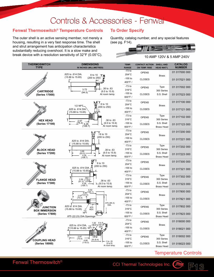
Controls & Accessories - FenwalControls & Accessories - FenwalFenwal Thermoswitch® Temperature ControlsThe outer shell is an active sensing member, not merely a housing, resulting in a very fast response time. The shell and strut arrangement has anticipation characteristics substantially reducing overshoot. It is a slow make and break device with a resolution sensitivity of 32°F (0.05°C).
Fenwal Thermoswitch®
Temperature Controls
10 AMP 120V & 5 AMP 240V
-73 to316°C
OPENS 01 017000 000
-100 to400°F /
BrassCLOSES 01 017021 000
OPENS Type 01 017002 000
-100 to600°F /
300 SeriesCLOSES S.S. Shell 01 017023 000
OPENS 01 017100 000Brass
CLOSES 01 017121 000
-73 to204°C
OPENSType 01 017102 000
300 Series
CLOSES S.S. Shell 01 017123 000
-73 to316°C
Brass Head
OPENS 01 017200 000Brass
CLOSES 01 017221 000
-73 to204°C
OPENSType 01 017202 000
300 Series
CLOSES S.S. Shell 01 017223 000
-73 to316°C
Brass Head
OPENS 01 017300 000Brass
CLOSES 01 017321 000
-73 to204°C
OPENSType 01 017302 000
300 Series
CLOSES S.S. Shell 01 017323 000
-73 to316°C
Brass Head
OPENS 01 017800 000Brass
CLOSES 01 017821 000
-73 to204°C
OPENSType 01 017802 000
300 Series
CLOSES S.S. Shell 01 017823 000
-73 to316°C
Brass Head
OPENS 01 018000 000Brass
CLOSES 01 018021 000
-73 to204°C
OPENSType 01 018002 000
300 Series
CLOSES S.S. Shell 01 018023 000
-73 to316°C
Brass Head
0 to .25(0 to 6)
At room temp.
6 to 8(150 to
200).625 to .614 DIA.(15.88 to 15.65)
1/2NPT
1.00HEX
.25 (6.4)4.66(118.3)
2.97(75.4)
6.50(165.1)4.84
(123.0)2.97(75.4)
.375 (95.3)DIA.
.875 (22.23) DIA.Openings
.875HEX1/2
NPT
.625 to .614 DIA.(15.88 to 15.65)
.062(1.59)
.625 to .614 DIA.(15.88 to 15.65)
3.59(91.3)
4.28(108.7)
8 to 10(200 to 250)
.38 to .63(9.5 to 15.9)
At room temp.
3.66(93.0)
4.28(108.7)
8 to 10(200 to 250)
.625 to .614 DIA.(15.88 to 15.65)
.625 to .614 DIA.(15.88 to 15.65)
8 to 10(200 to 250)
.38 to .63(9.5 to 15.9)
At room temp.
3.72(94.5)
8 to 10(200 to 250)
.38 to .63(9.5 to 15.9)
At room temp.4.28
(108.7)
2.97(75.4)
.625 to .614 DIA.(15.88 to 15.65)
1/2 NPT
COUPLING HEAD(Series 18000)
JUNCTIONBOX IMMERSION
(Series 17800)
FLANGE HEAD(Series 17300)
BLOCK HEAD(Series 17200)
HEX HEAD(Series 17100)
CARTRIDGE(Series 17000)
THERMOSWITCH DIMENSIONS TEMP. CONTACT ACTION SHELL AND CATALOGTYPE IN INCHES (MILLIMETRES) RANGE ON TEMP. RISE HEAD MAT'L NUMBER
.38 to .63(9.5 to 15.9)
At room temp.
-73 to204°C
-100 to400°F /
-100 to600°F /
-100 to400°F /
-100 to600°F /
-100 to400°F /
-100 to600°F /
-100 to400°F /
-100 to600°F /
-100 to400°F /
-100 to600°F /
CCI Thermal Technologies Inc.F14 F15Caloritech™
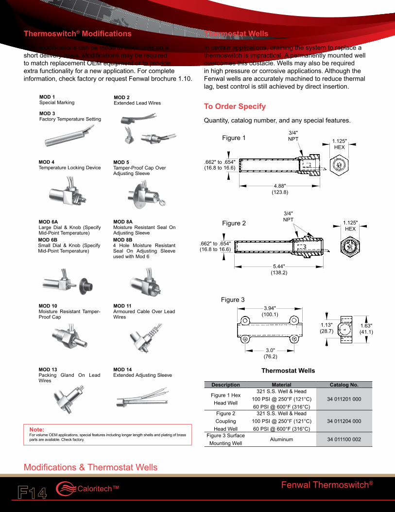
Thermoswitch® ModificationsMost modifications can be made to stock units on a short delivery basis. Modifications may be required to match replacement OEM equipment or to provide extra functionality for a new application. For complete information, check factory or request Fenwal brochure 1.10.
Thermostat WellsIn certain applications, draining the system to replace a thermoswitch is impractical. A permanently mounted well overcomes this obstacle. Wells may also be required in high pressure or corrosive applications. Although the Fenwal wells are accurately machined to reduce thermal lag, best control is still achieved by direct insertion.
To Order SpecifyQuantity, catalog number, and any special features.
Thermostat Wells
Description Material Catalog No.
Figure 1 Hex Head Well
321 S.S. Well & Head 100 PSI @ 250°F (121°C) 60 PSI @ 600°F (316°C)
34 011201 000
Figure 2 Coupling
Head Well
321 S.S. Well & Head 100 PSI @ 250°F (121°C) 60 PSI @ 600°F (316°C)
34 011204 000
Figure 3 Surface Mounting Well
Aluminum 34 011100 002
MOD 8B4 Hole Moisture ResistantSeal On Adjusting Sleeveused with Mod 6
MOD 6BSmall Dial & Knob (SpecifyMid-Point Temperature)
MOD 2Extended Lead Wires
MOD 1Special Marking
MOD 3Factory Temperature Setting
MOD 14Extended Adjusting Sleeve
MOD 13Packing Gland On LeadWires
MOD 11Armoured Cable Over LeadWires
MOD 10Moisture Resistant Tamper-Proof Cap
MOD 8AMoisture Resistant Seal OnAdjusting Sleeve
MOD 6ALarge Dial & Knob (SpecifyMid-Point Temperature)
MOD 5Tamper-Proof Cap OverAdjusting Sleeve
MOD 4Temperature Locking Device
Fenwal Thermoswitch®
Modifications & Thermostat Wells
Note:For volume OEM applications, special features including longer length shells and plating of brass parts are available. Check factory.
3/4"NPT
.662" to .654"(16.8 to 16.6)
Figure 1 1.125"HEX
4.88"(123.8)
3/4"NPTFigure 2 1.125"
HEX
5.44"(138.2)
.662" to .654"(16.8 to 16.6)
Figure 33.94"
(100.1)
1.13"(28.7)
1.63"(41.1)
3.0"(76.2)
CCI Thermal Technologies Inc.F14 F15
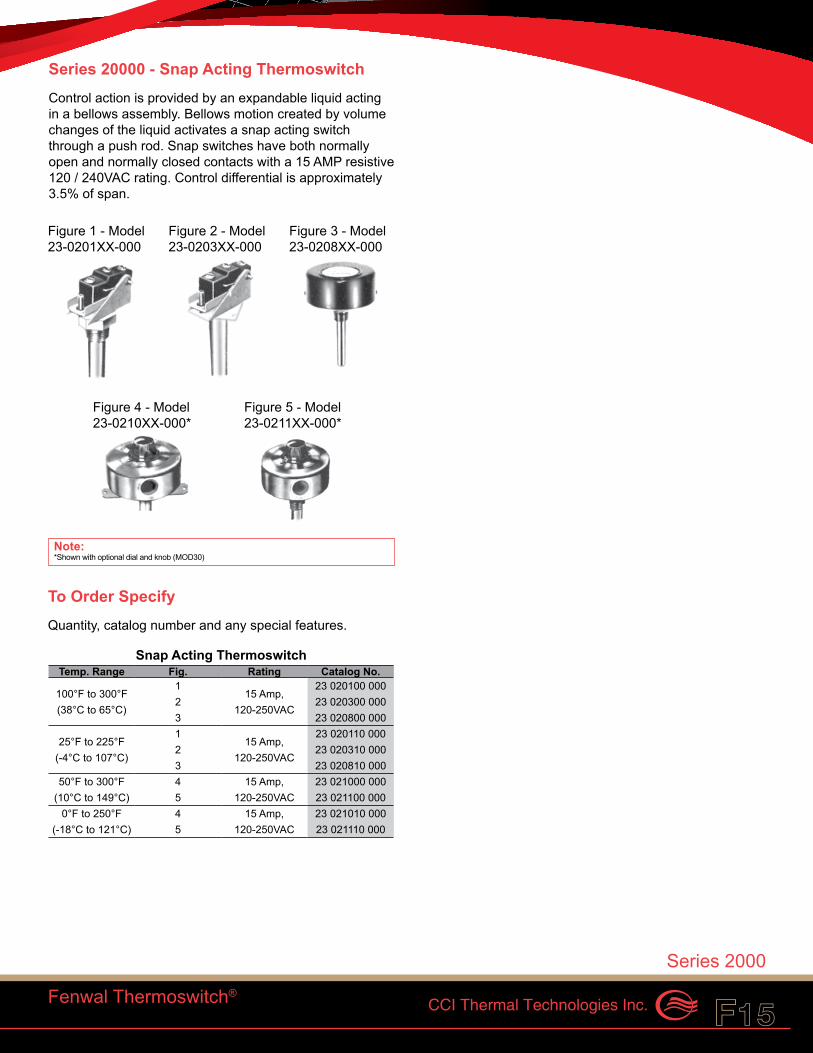
Series 20000 - Snap Acting ThermoswitchControl action is provided by an expandable liquid acting in a bellows assembly. Bellows motion created by volume changes of the liquid activates a snap acting switch through a push rod. Snap switches have both normally open and normally closed contacts with a 15 AMP resistive 120 / 240VAC rating. Control differential is approximately 3.5% of span.
Fenwal Thermoswitch®
Series 2000
Figure 1 - Model 23-0201XX-000
Figure 3 - Model 23-0208XX-000
Figure 2 - Model 23-0203XX-000
Figure 4 - Model 23-0210XX-000*
Figure 5 - Model 23-0211XX-000*
Note:*Shown with optional dial and knob (MOD30)
To Order SpecifyQuantity, catalog number and any special features.
Snap Acting Thermoswitch Temp. Range Fig. Rating Catalog No.
100°F to 300°F (38°C to 65°C)
115 Amp,
120-250VAC
23 020100 0002 23 020300 0003 23 020800 000
25°F to 225°F (-4°C to 107°C)
115 Amp,
120-250VAC
23 020110 0002 23 020310 0003 23 020810 000
50°F to 300°F (10°C to 149°C)
4 15 Amp, 120-250VAC
23 021000 0005 23 021100 000
0°F to 250°F (-18°C to 121°C)
4 15 Amp, 120-250VAC
23 021010 0005 23 021110 000
CCI Thermal Technologies Inc.F16 F17Caloritech™
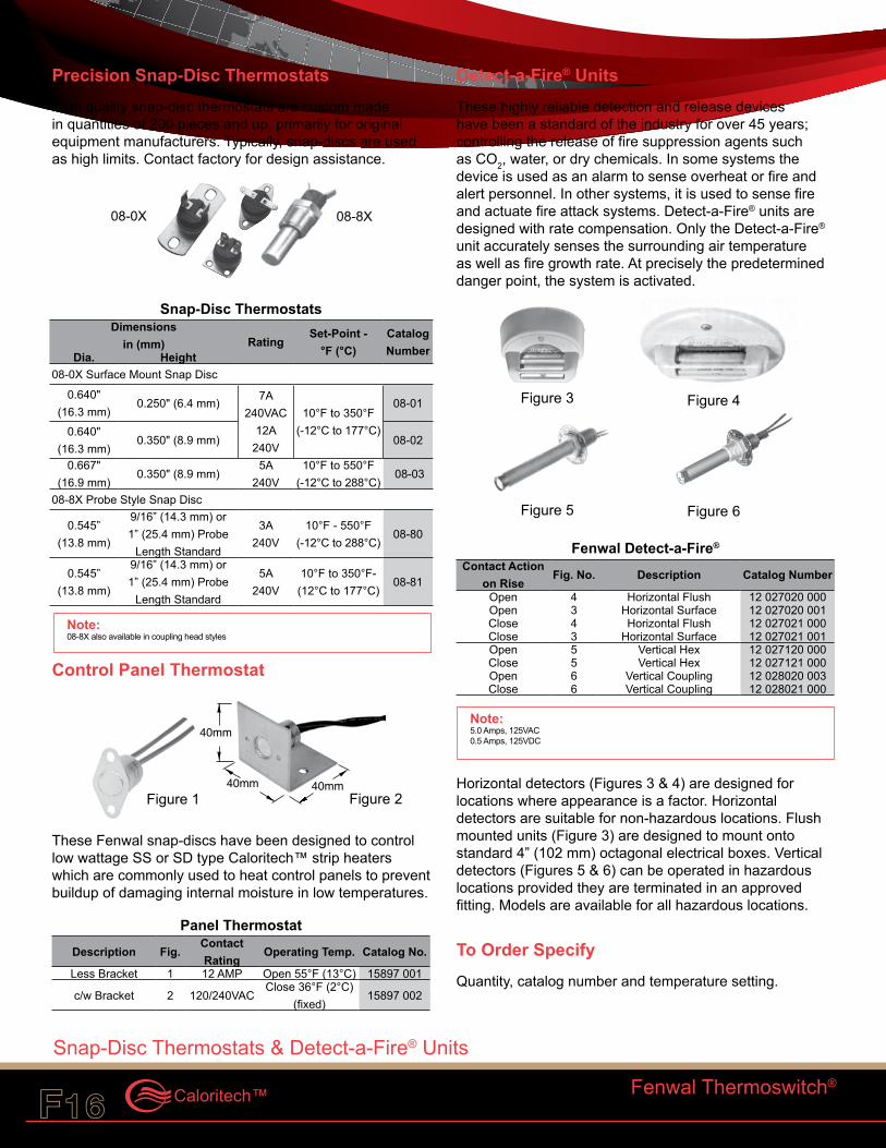
Precision Snap-Disc ThermostatsHigh quality snap-disc thermostats are custom made in quantities of 200 pieces and up, primarily for original equipment manufacturers. Typically, snap-discs are used as high limits. Contact factory for design assistance.
Snap-Disc Thermostats Dimensions
in (mm) RatingSet-Point -
°F (°C)Catalog NumberDia. Height
08-0X Surface Mount Snap Disc
0.640" (16.3 mm)
0.250" (6.4 mm) 7A 240VAC
12A 240V
10°F to 350°F (-12°C to 177°C)
08-01
0.640" (16.3 mm)
0.350" (8.9 mm) 08-02
0.667" (16.9 mm)
0.350" (8.9 mm)5A
240V10°F to 550°F
(-12°C to 288°C) 08-03
08-8X Probe Style Snap Disc
0.545” (13.8 mm)
9/16” (14.3 mm) or 1” (25.4 mm) Probe
Length Standard
3A 240V
10°F - 550°F (-12°C to 288°C)
08-80
0.545” (13.8 mm)
9/16” (14.3 mm) or 1” (25.4 mm) Probe
Length Standard
5A 240V
10°F to 350°F- (12°C to 177°C)
08-81
Control Panel Thermostat
These Fenwal snap-discs have been designed to control low wattage SS or SD type Caloritech™ strip heaters which are commonly used to heat control panels to prevent buildup of damaging internal moisture in low temperatures.
Panel Thermostat Description Fig.
Contact Rating
Operating Temp. Catalog No.
Less Bracket 1 12 AMP Open 55°F (13°C) 15897 001
c/w Bracket 2 120/240VACClose 36°F (2°C)
(fixed)15897 002
Detect-a-Fire® UnitsThese highly reliable detection and release devices have been a standard of the industry for over 45 years; controlling the release of fire suppression agents such as CO2, water, or dry chemicals. In some systems the device is used as an alarm to sense overheat or fire and alert personnel. In other systems, it is used to sense fire and actuate fire attack systems. Detect-a-Fire® units are designed with rate compensation. Only the Detect-a-Fire® unit accurately senses the surrounding air temperature as well as fire growth rate. At precisely the predetermined danger point, the system is activated.
Fenwal Detect-a-Fire® Contact Action
on RiseFig. No. Description Catalog Number
Open 4 Horizontal Flush 12 027020 000Open 3 Horizontal Surface 12 027020 001Close 4 Horizontal Flush 12 027021 000Close 3 Horizontal Surface 12 027021 001Open 5 Vertical Hex 12 027120 000Close 5 Vertical Hex 12 027121 000Open 6 Vertical Coupling 12 028020 003Close 6 Vertical Coupling 12 028021 000
Horizontal detectors (Figures 3 & 4) are designed for locations where appearance is a factor. Horizontal detectors are suitable for non-hazardous locations. Flush mounted units (Figure 3) are designed to mount onto standard 4” (102 mm) octagonal electrical boxes. Vertical detectors (Figures 5 & 6) can be operated in hazardous locations provided they are terminated in an approved fitting. Models are available for all hazardous locations.
To Order Specify Quantity, catalog number and temperature setting.
Note:08-8X also available in coupling head styles
08-8X08-0X
40mm40mmFigure 2
40mm
Figure 1
Figure 3
Figure 6Figure 5
Figure 4
Note:5.0 Amps, 125VAC0.5 Amps, 125VDC
Fenwal Thermoswitch®
Snap-Disc Thermostats & Detect-a-Fire® Units
CCI Thermal Technologies Inc.F16 F17
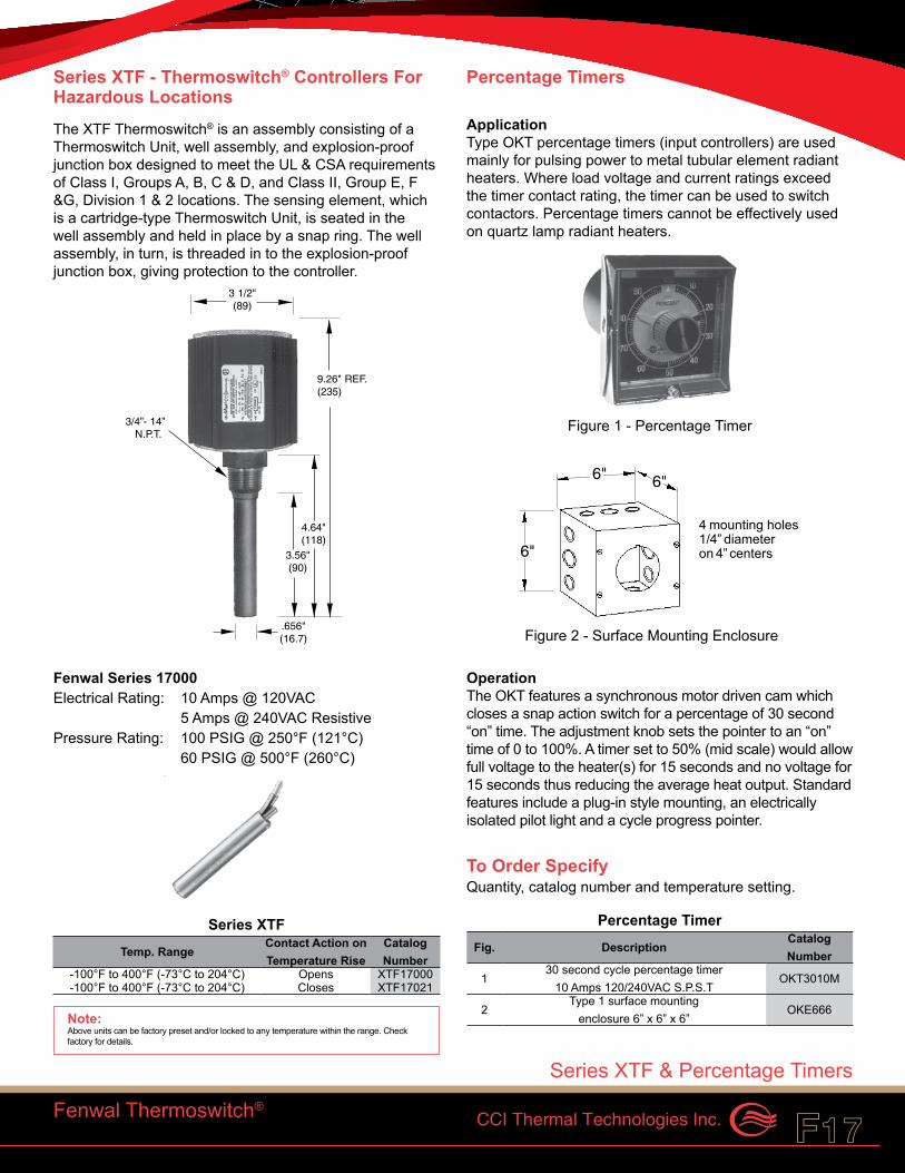
Series XTF - Thermoswitch® Controllers For Hazardous LocationsThe XTF Thermoswitch® is an assembly consisting of a Thermoswitch Unit, well assembly, and explosion-proof junction box designed to meet the UL & CSA requirements of Class I, Groups A, B, C & D, and Class II, Group E, F &G, Division 1 & 2 locations. The sensing element, which is a cartridge-type Thermoswitch Unit, is seated in the well assembly and held in place by a snap ring. The well assembly, in turn, is threaded in to the explosion-proof junction box, giving protection to the controller.
Fenwal Series 17000Electrical Rating: 10 Amps @ 120VAC 5 Amps @ 240VAC ResistivePressure Rating: 100 PSIG @ 250°F (121°C) 60 PSIG @ 500°F (260°C)
Series XTF Temp. Range
Contact Action on Temperature Rise
Catalog Number
-100°F to 400°F (-73°C to 204°C) Opens XTF17000-100°F to 400°F (-73°C to 204°C) Closes XTF17021
Percentage Timers
Application Type OKT percentage timers (input controllers) are used mainly for pulsing power to metal tubular element radiant heaters. Where load voltage and current ratings exceed the timer contact rating, the timer can be used to switch contactors. Percentage timers cannot be effectively used on quartz lamp radiant heaters.
Operation The OKT features a synchronous motor driven cam which closes a snap action switch for a percentage of 30 second “on” time. The adjustment knob sets the pointer to an “on” time of 0 to 100%. A timer set to 50% (mid scale) would allow full voltage to the heater(s) for 15 seconds and no voltage for 15 seconds thus reducing the average heat output. Standard features include a plug-in style mounting, an electrically isolated pilot light and a cycle progress pointer.
To Order Specify Quantity, catalog number and temperature setting.
Percentage Timer Fig. Description
Catalog Number
130 second cycle percentage timer
10 Amps 120/240VAC S.P.S.TOKT3010M
2Type 1 surface mounting
enclosure 6” x 6” x 6”OKE666
Fenwal Thermoswitch®
3 1/2"(89)
3/4” - 14”N.P.T.
3.56"(90)
.656"(16.7)
4.64"(118)
9.26" REF.(235)
Note:Above units can be factory preset and/or locked to any temperature within the range. Check factory for details.
4 mounting holes1/4” diameteron 4” centers
6" 6"
6"
Series XTF & Percentage Timers
Figure 1 - Percentage Timer
Figure 2 - Surface Mounting Enclosure
CCI Thermal Technologies Inc.F18 F19Caloritech™
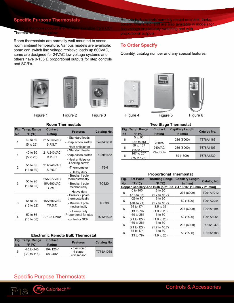
Specific Purpose ThermostatsSome of the more popular thermostats available from CCI Thermal are shown below.
Room thermostats are normally wall mounted to sense room ambient temperature. Various models are available: some can switch line voltage resistive loads up 600VAC, some are designed for 24VAC low voltage systems and others have 0-135 Ω proportional outputs for step controls and SCR’s.
Remote bulb controls normally mount on ducts, tanks, boilers, ovens, etc. and are also available in models for line voltage or pilot duty switching and with proportional outputs.
To Order SpecifyQuantity, catalog number and any special features.
Controls & Accessories
Figure 5Figure 4 Figure 6Figure 2 Figure 3Figure 1
Room Thermostats Fig. No.
Temp. Range °F (°C)
Contact Rating
Features Catalog No.
140 to 80 (5 to 25)
21A 240VAC S.P.S.T.
- Standard leads - Snap action switch
- Heat anticipatorT498A1786
140 to 80 (5 to 25)
21A 240VAC D.P.S.T
- Standard leads - Snap action switch
- Heat anticipatorT498B1652
255 to 85
(13 to 30)21A 240VAC
S.P.S.T.
-Locking screw -Thermometer - Heavy duty
176-6
355 to 90
(13 to 32)
25A 277VAC 15A 600VAC
D.P.S.T.
- Breaks 1 pole thermostatically - Breaks 1 pole mechanically - Heavy duty
TC620
355 to 90
(13 to 32)15A 600VAC
T.P.S.T.
- Breaks 2 poles thermostatically - Breaks 1 pole mechanically - Heavy duty
TC630
450 to 86
(10 to 30)0 - 135 Ohms
- Proportional for step control or SCR
T921A1522
Electronic Remote Bulb Thermostat Fig. No.
Temp. Range °F (°C)
Contact Rating
Features Catalog No.
5-20 to 240
(-29 to 116)10A 120V 5A 240V
- Electronic 4 stage
c/w sensorT775A1035
Two Stage Thermostat Fig. No.
Temp. Range °F (°C)
Contact Rating
Capillary Length in (mm)
Catalog No.
65 to 95
(-15 to 35) 200VA 240VAC
Pilot Duty
236 (6000) T678A1163
659 to 167 (15 to 75)
236 (6000) T678A1403
6167 to 257 (75 to 125)
59 (1500) T678A1239
Proportional Thermostat Fig. No.
Set Point °F (°C)
Throttling Range °F (°C)
Capillary Length in (mm)
Catalog No.
Copper Capillary And Bulb [1/2” Dia. x 4 13/16” (13 mm x 21 mm)]
60 to 100
(-18 to 38)3 to 30
(1.7 to 16.7)236 (6000) T991A1012
6-29 to 70
(-34 to 21)3 to 30
(1.7 to 16.7)59 (1500) T991A2044
655 to 174 (13 to 79)
3.5 to 36 (1.9 to 20)
236 (6000) T991A1194
6160 to 261 (71 to 127)
3 to 30 (1.9 to 20)
59 (1500) T991A1061
6160 to 261 (71 to 127)
3 to 30 (1.7 to 16.7)
236 (6000) T991A10479
655 to 174 (13 to 79)
3 to 30 (1.9 to 20)
59 (1500) T991A1186
Specific Purpose Thermostats
Specific Purpose Thermostats
CCI Thermal Technologies Inc.F18 F19
Series UT
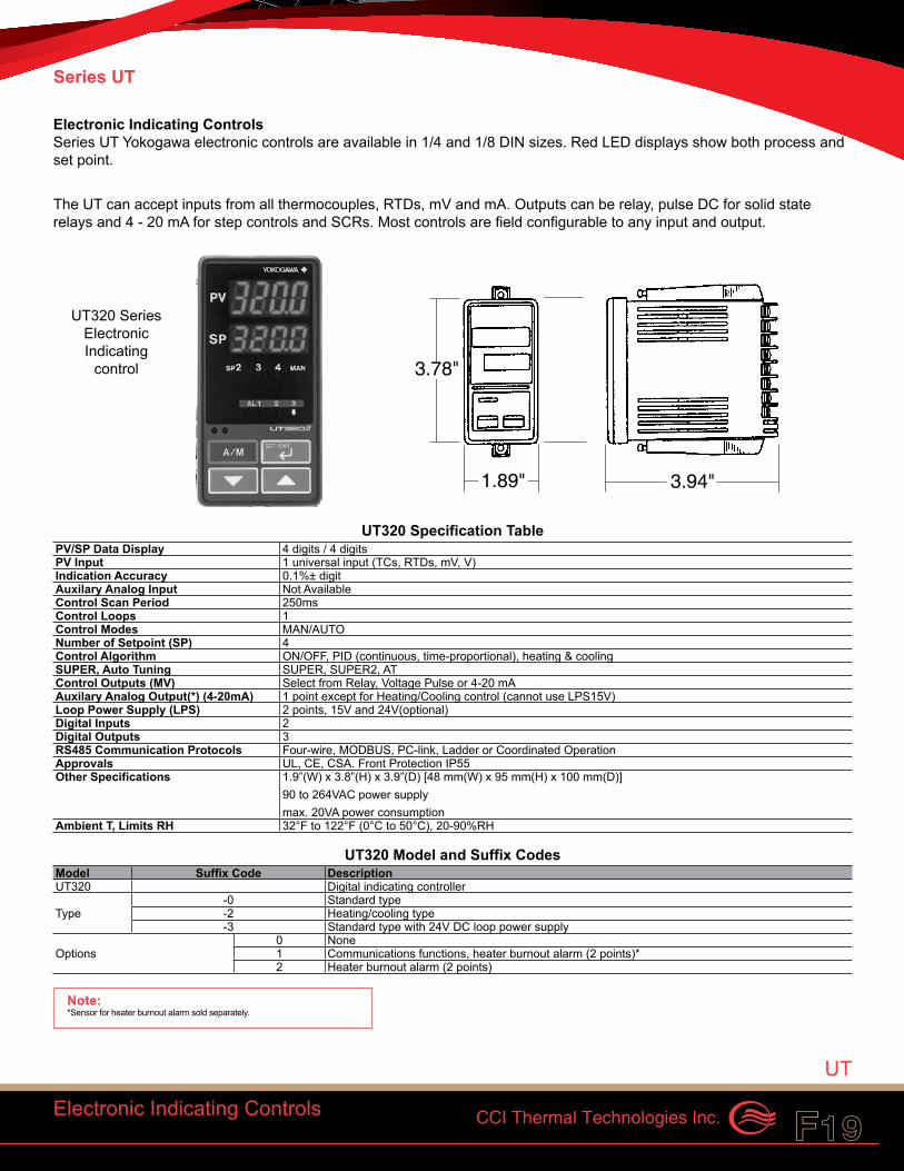
Electronic Indicating Controls Series UT Yokogawa electronic controls are available in 1/4 and 1/8 DIN sizes. Red LED displays show both process and set point.
The UT can accept inputs from all thermocouples, RTDs, mV and mA. Outputs can be relay, pulse DC for solid state relays and 4 - 20 mA for step controls and SCRs. Most controls are field configurable to any input and output.
Electronic Indicating Controls
1.89" 3.94"
3.78"
UT320 Specification Table PV/SP Data Display 4 digits / 4 digitsPV Input 1 universal input (TCs, RTDs, mV, V)Indication Accuracy 0.1%± digitAuxilary Analog Input Not AvailableControl Scan Period 250msControl Loops 1Control Modes MAN/AUTONumber of Setpoint (SP) 4Control Algorithm ON/OFF, PID (continuous, time-proportional), heating & coolingSUPER, Auto Tuning SUPER, SUPER2, ATControl Outputs (MV) Select from Relay, Voltage Pulse or 4-20 mAAuxilary Analog Output(*) (4-20mA) 1 point except for Heating/Cooling control (cannot use LPS15V)Loop Power Supply (LPS) 2 points, 15V and 24V(optional)Digital Inputs 2Digital Outputs 3RS485 Communication Protocols Four-wire, MODBUS, PC-link, Ladder or Coordinated OperationApprovals UL, CE, CSA. Front Protection IP55Other Specifications 1.9”(W) x 3.8”(H) x 3.9”(D) [48 mm(W) x 95 mm(H) x 100 mm(D)]
90 to 264VAC power supply max. 20VA power consumption
Ambient T, Limits RH 32°F to 122°F (0°C to 50°C), 20-90%RH
UT320 Model and Suffix Codes Model Suffix Code DescriptionUT320 Digital indicating controller
Type-0 Standard type-2 Heating/cooling type-3 Standard type with 24V DC loop power supply
Options0 None1 Communications functions, heater burnout alarm (2 points)*2 Heater burnout alarm (2 points)
Note:*Sensor for heater burnout alarm sold separately.
UT320 Series Electronic Indicating
control
UT

CCI Thermal Technologies Inc.F20 F21Caloritech™
UT350/UT450 Specification Table UT350 UT450
PV/SP Data Display 4 digits / digits 5 digits / 5 digitsPV Input 1 universal input (TCs, RTDs, mV, V)Indication Accuracy 0.1%+1 digitAuxilary Analog Input Not Available 1 for remote SPControl Scan Period 250ms 200msControl Loops 1 1Control Modes MAN/AUTO MAN/AUTO/CAS,, RUN/STOPNumber of Setpoint(SP) 4 8Control Algorithm ON/OFF, time-proportional PID, ON/OFF, 3 position, time-proportional
continuous PID, heating & cooling PID, continuous PID, heating & coolingSUPER, Auto Tuning SUPER, SUPER2, ATControl Outputs(MV) Select from Relay, Voltage Pulse or 4-20 mAAuxilary Analog Output(*)(4-20mA) 1 point except for Heating/Cooling 1 point (cannot use with LPS15V)
control (cannot use with LPS15V) 2 points when MV is relay outputLoop Power Supply (LPS) 2 points, 15V and 24V (optional)Digital Inputs 2 2,3,6 or 7Digital Outputs 3 3 or 4RS485 Communication Protocols Four-wire, MODBUS, PC-link, Ladder or Coordinated OperationApprovals UL, CE, CSA. Front Protection IP55Other Specifications 96(W) x 96(H) x 100(D) mm, 90 to 264VAC power supply
max. 20VA power consumptionAmbient T, Limits RH 32°F to 122°F (0°C to 50°C), 20-90%RH
Electronic Indicating Controls
UT350/UT450 Series Electronic Indicating Control
3.78"
3.78" 3.94"
UT350 Model and Suffix Codes Model Suffix Code DescriptionUT350 Digital indicating controller
Type-0 Standard type-2 Heating/cooling type-3 Std type with 24V DC loop
Options
0 None
1Communication functions heater burnout alarm (2 pts)*
2 heater burnout alarm (2 pts)
To Order SpecifyQuantity and catalog number.
UT450 Model and Suffix Codes Model Suffix Code DescriptionUT450 Digital indicating controller
Type
-0 Standard type-1 Position-proportional type-2 Heating/cooling type-3 Std type with 24V DC loop
-4Position-proportional type with 24V DC loop power supply
Options
0 None
1Comm. Functions, remote input, 5 add. Dls, 1 add. Alarm
2Comm. Functions, remote input, 1 add. Dl
3 4 add. Dls, 1 add. Alarm4 Remote input, 1 add. Dl
Note:*Sensor for heater burnout alarm sold separately.
UT
CCI Thermal Technologies Inc.F20 F21
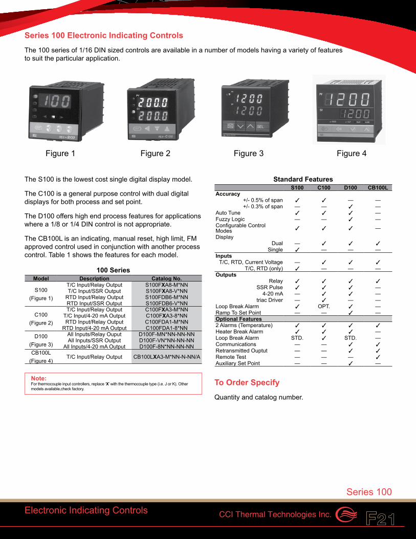
The S100 is the lowest cost single digital display model.
The C100 is a general purpose control with dual digital displays for both process and set point.
The D100 offers high end process features for applications where a 1/8 or 1/4 DIN control is not appropriate.
The CB100L is an indicating, manual reset, high limit, FM approved control used in conjunction with another process control. Table 1 shows the features for each model.
100 Series Model Description Catalog No.
S100 (Figure 1)
T/C Input/Relay Output S100FXA8-M*NNT/C Input/SSR Output S100FXA8-V*NN
RTD Input/Relay Output S100FDB6-M*NNRTD Input/SSR Output S100FDB6-V*NN
C100 (Figure 2)
T/C Input/Relay Output C100FXA3-M*NNT/C Input/4-20 mA Output C100FXA3-8*NNRTD Input/Relay Output C100FDA1-M*NN
RTD Input/4-20 mA Output C100FDA1-8*NND100
(Figure 3)
All Inputs/Relay Ouput D100F-MN*NN-NN-NNAll Inputs/SSR Output D100F-VN*NN-NN-NN
All Inputs/4-20 mA Output D100F-8N*NN-NN-NNCB100L
(Figure 4)T/C Input/Relay Output CB100LXA3-M*NN-N-NN/A
Standard Features S100 C100 D100 CB100L
Accuracy+/- 0.5% of span 3 3 — —+/- 0.3% of span — — 3 —
Auto Tune 3 3 3 —Fuzzy Logic — — 3 —Configurable Control Modes 3 3 3 —Display
Dual — 3 3 3Single 3 — — —
InputsT/C, RTD, Current Voltage — 3 3 3
T/C, RTD (only) 3 — — —Outputs
Relay 3 3 3 3SSR Pulse 3 3 3 —
4-20 mA — 3 3 —triac Driver — 3 — —
Loop Break Alarm 3 OPT. 3 —Ramp To Set Point — — 3 —Optional Features2 Alarms (Temperature) 3 3 3 3Heater Break Alarm 3 3 3 —Loop Break Alarm STD. 3 STD. —Communications — — 3 3Retransmitted Ouptut — — 3 3Remote Test — — — 3Auxiliary Set Point — — 3 —
To Order SpecifyQuantity and catalog number.
Electronic Indicating Controls
Series 100
Figure 1 Figure 2 Figure 3 Figure 4
Series 100 Electronic Indicating ControlsThe 100 series of 1/16 DIN sized controls are available in a number of models having a variety of features to suit the particular application.
Note:For thermocouple input controllers, replace ‘X’ with the thermocouple type (i.e. J or K). Other models available,check factory.
CCI Thermal Technologies Inc.F22 F23Caloritech™
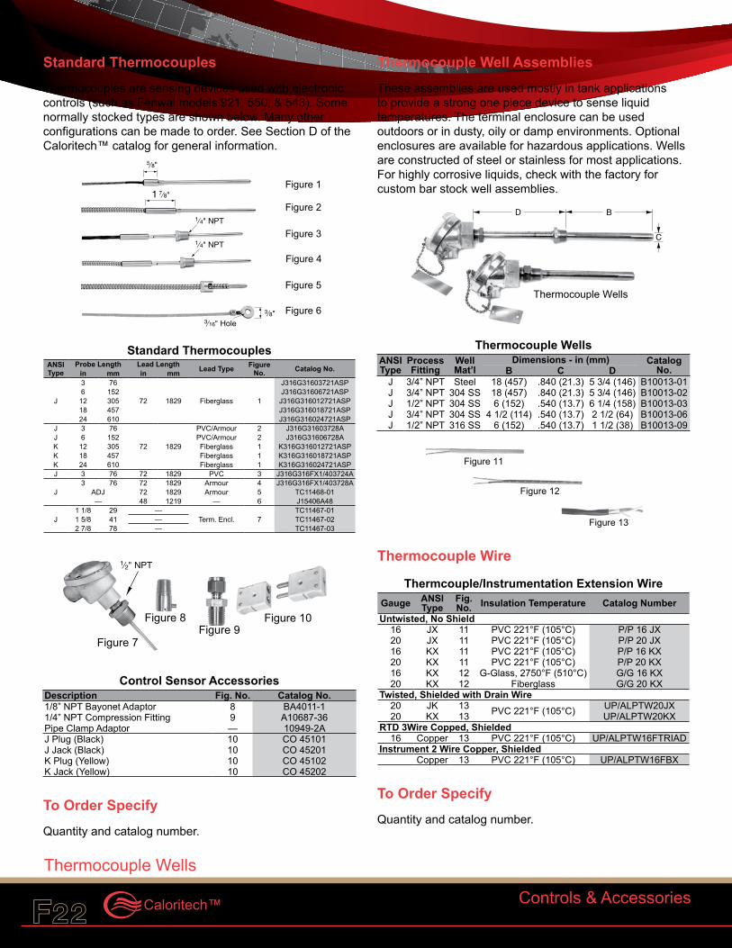
Standard ThermocouplesThermocouples are sensing devices used with electronic controls (such as Fenwal models 921, 550, & 543). Some normally stocked types are shown below. Many other configurations can be made to order. See Section D of the Caloritech™ catalog for general information.
Standard Thermocouples ANSI Type
Probe Length Lead Length Lead Type Figure No. Catalog No.in mm in mm
J
3 76
72 1829 Fiberglass 1
J316G31603721ASP6 152 J316G31606721ASP12 305 J316G316012721ASP18 457 J316G316018721ASP24 610 J316G316024721ASP
J 3 76
72 1829
PVC/Armour 2 J316G31603728AJ 6 152 PVC/Armour 2 J316G31606728AK 12 305 Fiberglass 1 K316G316012721ASPK 18 457 Fiberglass 1 K316G316018721ASPK 24 610 Fiberglass 1 K316G316024721ASPJ 3 76 72 1829 PVC 3 J316G316FX1/403724A
J3 76 72 1829 Armour 4 J316G316FX1/403728A
ADJ 72 1829 Armour 5 TC11468-01— 48 1219 — 6 J15406A48
J1 1/8 29 —
Term. Encl. 7TC11467-01
1 5/8 41 — TC11467-022 7/8 78 — TC11467-03
Control Sensor Accessories Description Fig. No. Catalog No.1/8” NPT Bayonet Adaptor 8 BA4011-11/4” NPT Compression Fitting 9 A10687-36Pipe Clamp Adaptor — 10949-2AJ Plug (Black) 10 CO 45101J Jack (Black) 10 CO 45201K Plug (Yellow) 10 CO 45102K Jack (Yellow) 10 CO 45202
To Order SpecifyQuantity and catalog number.
Thermocouple Well AssembliesThese assemblies are used mostly in tank applications to provide a strong one piece device to sense liquid temperatures. The terminal enclosure can be used outdoors or in dusty, oily or damp environments. Optional enclosures are available for hazardous applications. Wells are constructed of steel or stainless for most applications. For highly corrosive liquids, check with the factory for custom bar stock well assemblies.
Thermocouple Wells ANSI Type
Process Fitting
Well Mat’l
Dimensions - in (mm) Catalog No.B C D
J 3/4” NPT Steel 18 (457) .840 (21.3) 5 3/4 (146) B10013-01J 3/4” NPT 304 SS 18 (457) .840 (21.3) 5 3/4 (146) B10013-02J 1/2” NPT 304 SS 6 (152) .540 (13.7) 6 1/4 (158) B10013-03J 3/4” NPT 304 SS 4 1/2 (114) .540 (13.7) 2 1/2 (64) B10013-06J 1/2” NPT 316 SS 6 (152) .540 (13.7) 1 1/2 (38) B10013-09
Thermocouple Wire
Thermcouple/Instrumentation Extension Wire Gauge ANSI
TypeFig. No. Insulation Temperature Catalog Number
Untwisted, No Shield16 JX 11 PVC 221°F (105°C) P/P 16 JX20 JX 11 PVC 221°F (105°C) P/P 20 JX16 KX 11 PVC 221°F (105°C) P/P 16 KX20 KX 11 PVC 221°F (105°C) P/P 20 KX16 KX 12 G-Glass, 2750°F (510°C) G/G 16 KX20 KX 12 Fiberglass G/G 20 KX
Twisted, Shielded with Drain Wire20 JK 13 PVC 221°F (105°C) UP/ALPTW20JX20 KX 13 UP/ALPTW20KX
RTD 3Wire Copped, Shielded16 Copper 13 PVC 221°F (105°C) UP/ALPTW16FTRIAD
Instrument 2 Wire Copper, ShieldedCopper 13 PVC 221°F (105°C) UP/ALPTW16FBX
To Order SpecifyQuantity and catalog number.
1⁄2" NPT
Figure 7
Figure 8Figure 9
Figure 10
B
C
D
Thermocouple Wells
5⁄8"
Figure 1
3⁄8" Figure 6
Figure 5
Figure 4
1 7⁄8"
1⁄4" NPT
Figure 3
Figure 2
1⁄4" NPT
3⁄16" Hole
Controls & Accessories
Thermocouple Wells
Figure 12
Figure 11
Figure 13
Thermocouple Wells
CCI Thermal Technologies Inc.F22 F23
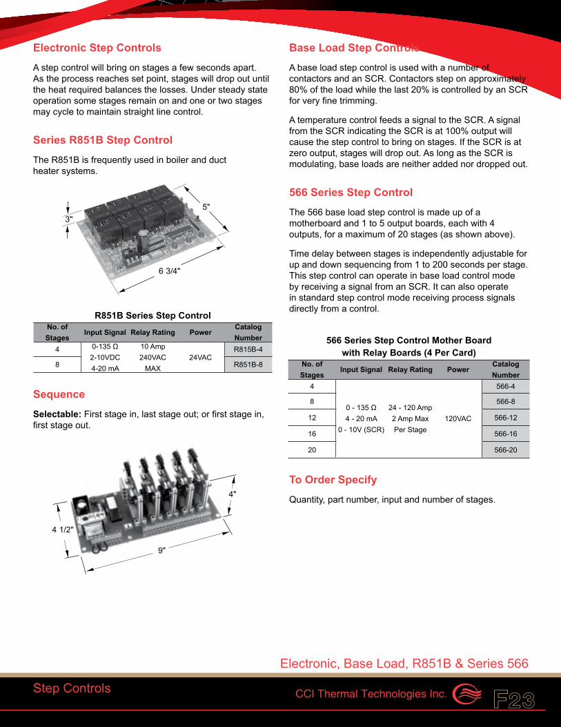
Electronic Step ControlsA step control will bring on stages a few seconds apart. As the process reaches set point, stages will drop out until the heat required balances the losses. Under steady state operation some stages remain on and one or two stages may cycle to maintain straight line control.
Series R851B Step ControlThe R851B is frequently used in boiler and duct heater systems.
R851B Series Step Control No. of Stages
Input Signal Relay Rating PowerCatalog Number
4 0-135 Ω 2-10VDC 4-20 mA
10 Amp 240VAC
MAX24VAC
R815B-4
8 R851B-8
SequenceSelectable: First stage in, last stage out; or first stage in, first stage out.
Base Load Step ControlsA base load step control is used with a number of contactors and an SCR. Contactors step on approximately 80% of the load while the last 20% is controlled by an SCR for very fine trimming.
A temperature control feeds a signal to the SCR. A signal from the SCR indicating the SCR is at 100% output will cause the step control to bring on stages. If the SCR is at zero output, stages will drop out. As long as the SCR is modulating, base loads are neither added nor dropped out.
566 Series Step ControlThe 566 base load step control is made up of a motherboard and 1 to 5 output boards, each with 4 outputs, for a maximum of 20 stages (as shown above).
Time delay between stages is independently adjustable for up and down sequencing from 1 to 200 seconds per stage. This step control can operate in base load control mode by receiving a signal from an SCR. It can also operate in standard step control mode receiving process signals directly from a control.
566 Series Step Control Mother Board with Relay Boards (4 Per Card)
No. of Stages
Input Signal Relay Rating PowerCatalog Number
4
0 - 135 Ω 4 - 20 mA
0 - 10V (SCR)
24 - 120 Amp 2 Amp Max Per Stage
120VAC
566-4
8 566-8
12 566-12
16 566-16
20 566-20
To Order Specify Quantity, part number, input and number of stages.
Step Controls
5"
6 3/4"
3"
4 1/2"
4"
9"
Electronic, Base Load, R851B & Series 566
CCI Thermal Technologies Inc.F24 F25Caloritech™
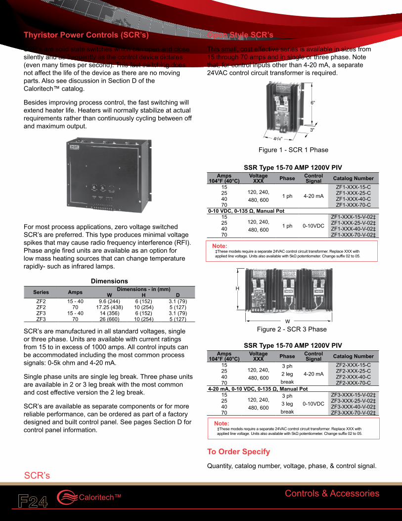
Thyristor Power Controls (SCR’s)SCR’s are solid state switches which can open and close silently and as frequently as the control device dictates (even many times per second). This fast switching does not affect the life of the device as there are no moving parts. Also see discussion in Section D of the Caloritech™ catalog.
Besides improving process control, the fast switching will extend heater life. Heaters will normally stabilize at actual requirements rather than continuously cycling between off and maximum output.
For most process applications, zero voltage switched SCR’s are preferred. This type produces minimal voltage spikes that may cause radio frequency interference (RFI).Phase angle fired units are available as an option for low mass heating sources that can change temperature rapidly- such as infrared lamps.
Dimensions Series Amps Dimensions - in (mm)
W H DZF2 15 - 40 9.6 (244) 6 (152) 3.1 (79)ZF2 70 17.25 (438) 10 (254) 5 (127)ZF3 15 - 40 14 (356) 6 (152) 3.1 (79)ZF3 70 26 (660) 10 (254) 5 (127)
SCR’s are manufactured in all standard voltages, single or three phase. Units are available with current ratings from 15 to in excess of 1000 amps. All control inputs can be accommodated including the most common process signals: 0-5k ohm and 4-20 mA.
Single phase units are single leg break. Three phase units are available in 2 or 3 leg break with the most common and cost effective version the 2 leg break.
SCR’s are available as separate components or for more reliable performance, can be ordered as part of a factory designed and built control panel. See pages Section D for control panel information.
Open Style SCR’sThis small, cost effective series is available in sizes from 15 through 70 amps and in single or three phase. Note that, for control inputs other than 4-20 mA, a separate 24VAC control circuit transformer is required.
SSR Type 15-70 AMP 1200V PIV Amps
104°F (40°C)Voltage
XXX Phase Control Signal Catalog Number
15120, 240, 480, 600
1 ph 4-20 mAZF1-XXX-15-C
25 ZF1-XXX-25-C40 ZF1-XXX-40-C70 ZF1-XXX-70-C
0-10 VDC, 0-135 Ω, Manual Pot15
120, 240, 480, 600
1 ph 0-10VDCZF1-XXX-15-V-02‡
25 ZF1-XXX-25-V-02‡40 ZF1-XXX-40-V-02‡70 ZF1-XXX-70-V-02‡
SSR Type 15-70 AMP 1200V PIV Amps
104°F (40°C)Voltage
XXX Phase Control Signal Catalog Number
15120, 240, 480, 600
3 ph 2 leg break
4-20 mAZF2-XXX-15-C
25 ZF2-XXX-25-C40 ZF2-XXX-40-C70 ZF2-XXX-70-C
4-20 mA, 0-10 VDC, 0-135 Ω, Manual Pot15
120, 240, 480, 600
3 ph 3 leg break
0-10VDCZF3-XXX-15-V-02‡
25 ZF3-XXX-25-V-02‡40 ZF3-XXX-40-V-02‡70 ZF3-XXX-70-V-02‡
To Order Specify Quantity, catalog number, voltage, phase, & control signal.
W
H
Controls & Accessories
Note:‡These models require a separate 24VAC control circuit transformer. Replace XXX with applied line voltage. Units also available with 5kΩ potentiometer. Change suffix 02 to 05.
43/4"
3"
6"
SCR’s
SCR’s
Figure 1 - SCR 1 Phase
Figure 2 - SCR 3 Phase
Note:‡These models require a separate 24VAC control circuit transformer. Replace XXX with applied line voltage. Units also available with 5kΩ potentiometer. Change suffix 02 to 05.
CCI Thermal Technologies Inc.F24 F25
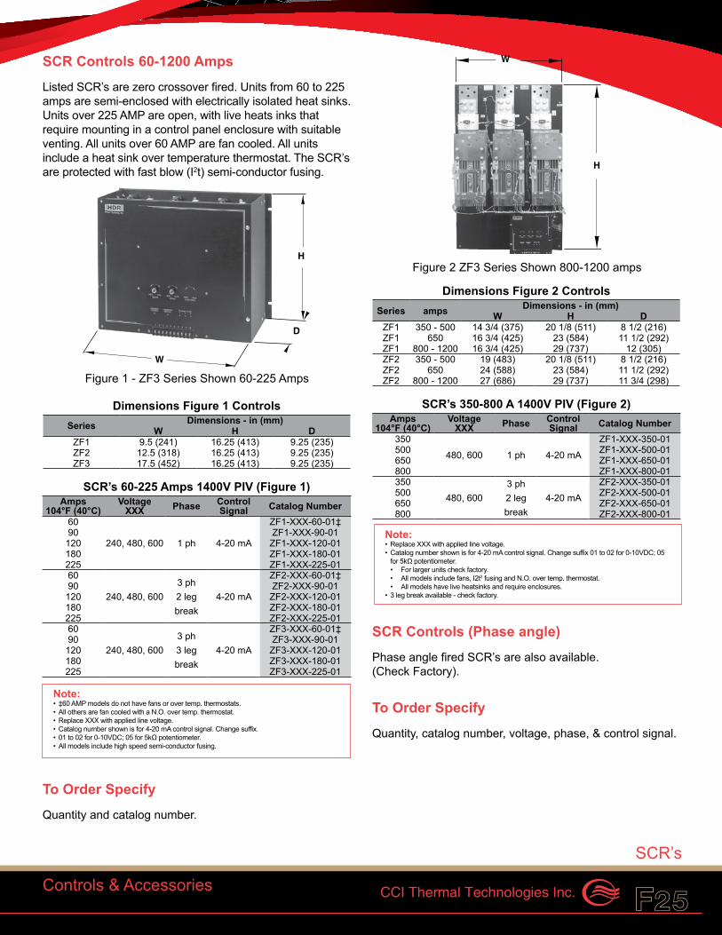
SCR Controls 60-1200 AmpsListed SCR’s are zero crossover fired. Units from 60 to 225 amps are semi-enclosed with electrically isolated heat sinks. Units over 225 AMP are open, with live heats inks that require mounting in a control panel enclosure with suitable venting. All units over 60 AMP are fan cooled. All units include a heat sink over temperature thermostat. The SCR’s are protected with fast blow (I2t) semi-conductor fusing.
Dimensions Figure 1 Controls Series Dimensions - in (mm)
W H DZF1 9.5 (241) 16.25 (413) 9.25 (235)ZF2 12.5 (318) 16.25 (413) 9.25 (235)ZF3 17.5 (452) 16.25 (413) 9.25 (235)
SCR’s 60-225 Amps 1400V PIV (Figure 1) Amps
104°F (40°C)Voltage
XXX Phase Control Signal Catalog Number
60
240, 480, 600 1 ph 4-20 mA
ZF1-XXX-60-01‡90 ZF1-XXX-90-01120 ZF1-XXX-120-01180 ZF1-XXX-180-01225 ZF1-XXX-225-0160
240, 480, 6003 ph 2 leg break
4-20 mA
ZF2-XXX-60-01‡90 ZF2-XXX-90-01120 ZF2-XXX-120-01180 ZF2-XXX-180-01225 ZF2-XXX-225-0160
240, 480, 6003 ph 3 leg break
4-20 mA
ZF3-XXX-60-01‡90 ZF3-XXX-90-01120 ZF3-XXX-120-01180 ZF3-XXX-180-01225 ZF3-XXX-225-01
To Order Specify Quantity and catalog number.
Dimensions Figure 2 Controls Series amps Dimensions - in (mm)
W H DZF1 350 - 500 14 3/4 (375) 20 1/8 (511) 8 1/2 (216)ZF1 650 16 3/4 (425) 23 (584) 11 1/2 (292)ZF1 800 - 1200 16 3/4 (425) 29 (737) 12 (305)ZF2 350 - 500 19 (483) 20 1/8 (511) 8 1/2 (216)ZF2 650 24 (588) 23 (584) 11 1/2 (292)ZF2 800 - 1200 27 (686) 29 (737) 11 3/4 (298)
SCR’s 350-800 A 1400V PIV (Figure 2) Amps
104°F (40°C)Voltage
XXX Phase Control Signal Catalog Number
350480, 600 1 ph 4-20 mA
ZF1-XXX-350-01500 ZF1-XXX-500-01650 ZF1-XXX-650-01800 ZF1-XXX-800-01350
480, 6003 ph 2 leg break
4-20 mAZF2-XXX-350-01
500 ZF2-XXX-500-01650 ZF2-XXX-650-01800 ZF2-XXX-800-01
SCR Controls (Phase angle) Phase angle fired SCR’s are also available. (Check Factory).
To Order Specify Quantity, catalog number, voltage, phase, & control signal.
H
D
W
Controls & Accessories
Note:• ‡60 AMP models do not have fans or over temp. thermostats. • All others are fan cooled with a N.O. over temp. thermostat. • Replace XXX with applied line voltage. • Catalog number shown is for 4-20 mA control signal. Change suffix.• 01 to 02 for 0-10VDC; 05 for 5kΩ potentiometer. • All models include high speed semi-conductor fusing.
W
H
SCR’s
Note:• Replace XXX with applied line voltage. • Catalog number shown is for 4-20 mA control signal. Change suffix 01 to 02 for 0-10VDC; 05
for 5kΩ potentiometer.• For larger units check factory.• All models include fans, I2t2 fusing and N.O. over temp. thermostat.• All models have live heatsinks and require enclosures.
• 3 leg break available - check factory.
Figure 1 - ZF3 Series Shown 60-225 Amps
Figure 2 ZF3 Series Shown 800-1200 amps

CCI Thermal Technologies Inc.F26 F27Caloritech™
High Temperature WireFor specific information on allowable current capacity and temperatures for wire refer to your regional Electrical Code. Wire ampacity decreases as the ambient temperature increases.
Other Gauges Heavier gauges are available. Consult factory.
High Temperature Wire 600V Max. - 3 Wires Max. In Raceway
GaugeMaximum Allowable
Wire Temp.Recommended Max. Amps at Ambient of Catalog
Number°F °C 86°F (30°C) 284°F (140°C)8 392 200 55 32 SEW-8
10 392 200 45 26 SEW-1012 392 200 30 17 SEW-1210 482 250 40 23 TCGT-1012 482 250 25 14 TCGT-12
To Order Specify Quantity and catalog number.
Flow SwitchesFlow Switches are typically used as proving switches to energize heaters only when sufficient flow is present. They are inserted into pipelines carrying non-corrosive and non-hazardous liquids. Flow rates from 3 to 700 G.P.M. can be accommodated in 1” to 8” (25 mm to 203 mm) pipe sizes.
Flow Switches Process
ConnectionSwitch Rating Exposure Catalog
NumberResistive Inductive
1” NPT 16A 277VAC Max 125VA 24-277VAC150PSIG (1034kPa)
F61KB-11
To Order Specify Quantity and catalog number.
Air Flow Switches.Pressure Differential Switch This device is used as an interlock to ensure sufficient air movement before a duct heater can be energized.
The pressure differential switch must be installed to a vertical surface.
Pressure Differential Switches Pressure Range Electrical Rating Catalog Number.05” to 12.0” WC (Field Adjustable)
15 amp Resistive 120 / 277VAC
300VA InductiveAFS-222
Sail Switch Sail switches are used to activate electrical equipment in response to airflow in a duct. Both normally open and normally closed contacts (SPDT) are provided with a 2.5 AMP 240VAC maximum resistive rating. The normally open contact makes at 250 fpm (1.3 m/s) and breaks below 75 fpm (0.4 m/s). The sail switch can be adapted to horizontal or vertical air flow.
Sail Switch Electrical
RatingAir Flow Maximum Air Temp. Catalog
NumberMin. Max. °F °C2.5A 240VAC 75 fpm 250 fpm 170 77 S688A1007
To Order Specify Quantity and catalog number.
Controls & Accessories
High Temperature Wires, Flow & Air Flow Switches
CCI Thermal Technologies Inc.F26 F27
Level Control (For Conductive Liquids)The SV series electronic liquid level control senses the resistance between remote mounted level probe electrodes (see type EH below). By altering the lengths of the electrodes, various combinations of high and low limit, heater ON-OFF and pump ON-OFF can occur as liquid levels change in the vessel.
When liquid is present, the SV220 de-energizes and the SV210 energizes. Otherwise both controls are the same.
Level Control Sensor Current <25 kΩs Relay Relay Rating Catalog Number
2.5 mA De-energizes 8 Amp 120VAC DPDT
SV220-1152.5 mA Energizes SV210-115
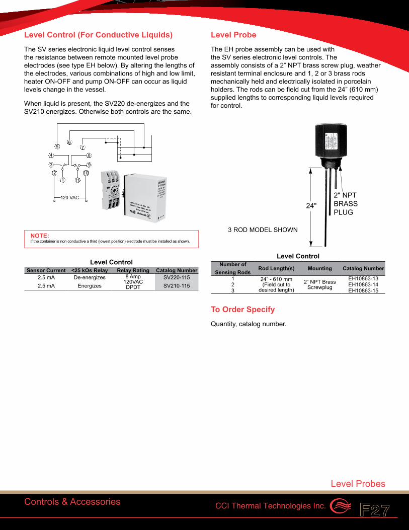
Level ProbeThe EH probe assembly can be used with the SV series electronic level controls. The assembly consists of a 2” NPT brass screw plug, weather resistant terminal enclosure and 1, 2 or 3 brass rods mechanically held and electrically isolated in porcelain holders. The rods can be field cut from the 24” (610 mm)supplied lengths to corresponding liquid levels required for control.
Level Control Number of
Sensing RodsRod Length(s) Mounting Catalog Number
1 24” - 610 mm (Field cut to
desired length)2” NPT Brass
ScrewplugEH10863-13
2 EH10863-143 EH10863-15
To Order Specify Quantity, catalog number.
120 VAC
87
6
1110
9
4
5
3
21
Controls & Accessories
NOTE:If the container is non conductive a third (lowest position) electrode must be installed as shown.
3 ROD MODEL SHOWN
24"2" NPTBRASSPLUG
Level Probes

CCI Thermal Technologies Inc.F28 F29Caloritech™
Notes:

CCI Thermal Technologies Inc.F28 F29
Notes:

CCI Thermal Technologies Inc.F30 F31Caloritech™
Notes:
CCI Thermal Technologies Inc.F30 F31Reference
Warranty
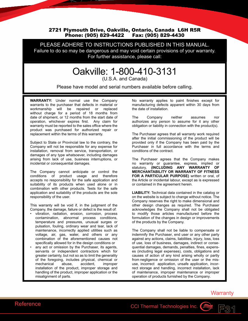
PLEASE ADHERE TO INSTRUCTIONS PUBLISHED IN THIS MANUAL.Failure to do so may be dangerous and may void certain provisions of your warranty.
For further assistance, please call:
WARRANTY: Under normal use the Company warrants to the purchaser that defects in material or workmanship will be repaired or replaced without charge for a period of 18 months from date of shipment, or 12 months from the start date of operation, whichever expires first. Any claim for warranty must be reported to the sales office where the product was purchased for authorized repair or replacement within the terms of this warranty.
Subject to State or Provincial law to the contrary, the Company will not be responsible for any expense for installation, removal from service, transportation, or damages of any type whatsoever, including damages arising from lack of use, business interruptions, or incidental or consequential damages.
The Company cannot anticipate or control the conditions of product usage and therefore accepts no responsibility for the safe application and suitability of its products when used alone or in combination with other products. Tests for the safe application and suitability of the products are the sole responsibility of the user.
This warranty will be void if, in the judgment of the Company, the damage, failure or defect is the result of:• vibration, radiation, erosion, corrosion, process
contamination, abnormal process conditions, temperature and pressures, unusual surges or pulsation, fouling, ordinary wear and tear, lack of maintenance, incorrectly applied utilities such as voltage, air, gas, water, and others or any combination of the aforementioned causes not specifically allowed for in the design conditions or
• any act or omission by the Purchaser, its agents, servants or independent contractors which for greater certainty, but not so as to limit the generality of the foregoing, includes physical, chemical or mechanical abuse, accident, improper installation of the product, improper storage and handling of the product, improper application or the misalignment of parts.
No warranty applies to paint finishes except for manufacturing defects apparent within 30 days from the date of installation.
The Company neither assumes nor authorizes any person to assume for it any other obligation or liability in connection with the product(s).
The Purchaser agrees that all warranty work required after the initial commissioning of the product will be provided only if the Company has been paid by the Purchaser in full accordance with the terms and conditions of the contract.
The Purchaser agrees that the Company makes no warranty or guarantee, express, implied or statutory, (INCLUDING ANY WARRANTY OF MERCHANTABILITY OR WARRANTY OF FITNESS FOR A PARTICULAR PURPOSE) written or oral, of the Article or incidental labour, except as is expressed or contained in the agreement herein.
LIABILITY: Technical data contained in the catalog or on the website is subject to change without notice. The Company reserves the right to make dimensional and other design changes as required. The Purchaser acknowledges the Company shall not be obligated to modify those articles manufactured before the formulation of the changes in design or improvements of the products by the Company.
The Company shall not be liable to compensate or indemnify the Purchaser, end user or any other party against any actions, claims, liabilities, injury, loss, loss of use, loss of business, damages, indirect or conse-quential damages, demands, penalties, fines, expens-es (including legal expenses), costs, obligations and causes of action of any kind arising wholly or partly from negligence or omission of the user or the mis-use, incorrect application, unsafe application, incor-rect storage and handling, incorrect installation, lack of maintenance, improper maintenance or improper operation of products furnished by the Company.
Edmonton Head Office1-800-661-8529(780) 466-3178F 780-468-5904
Oakville1-800-410-3131(905) 829-4422F 905-829-4430
Orillia1-877-325-3473(705) 325-3473F 705-325-2106
Houston1-855-219-2101(281) 506-2310F 281-506-2316
Denver(303) 979-7339F 303-979-7350
Oakville: 1-800-410-3131(U.S.A. and Canada)
Please have model and serial numbers available before calling.
2721 Plymouth Drive, Oakville, Ontario, Canada L6H R5RPhone: (905) 829-4422 Fax: (905) 829-4430
As a leader in advanced heating and filtration solutions with facilities across North America, CCI Thermal Technologies Inc. manufactures six of the top brands in industrial heating in addition to a comprehensive line of engineered industrial filtration products including:
VISIT WWW.CCITHERMAL.COM FOR DETAILED PRODUCT INFORMATION.
DriQuik™ provides components for infrared drying ovens. DriQuik™ utilizes a pioneered radiant oven technology established in the 1930s providing the industry standard in infrared radiant heating components.
Norseman™ is the most technologically advanced line of explosion-proof electric air heaters and heating accessories, including both forced air heaters and natural convection heaters, as well as unit heaters, panel heaters and thermostats. Norseman™ offers innovative, low maintenance solutions for a wide range of applications in a variety of industrial and commercial environments. Custom engineered heaters or heating systems are available for specialized applications.
3L Filters™ has satisfied the most demanding industrial filtration requirements for over 40 years. A broad range of standard and custom products includes liquid filters, strainers, separators, pressure vessels, and engineered products and systems. 3L Filters™ has special expertise for nuclear, petrochemical, water treatment and environmental applications.
Fastrax® has manufactured railroad track and switch heating since 1995. Fastrax® engineers complete heating packages for the rail industry. Fastrax® track and switch heaters are designed to provide the most efficient heat transfer on rail equipment and components for the coldest environments. In addition to heaters, Fastrax® manufactures fully automatic energy saving controls to complete the rail heating system.
Caloritech™ electric heaters, heating elements and heating accessories are well-known in the industry for their quality, reliability, performance and versatility. In addition to standard "off the shelf" industrial heaters and heating systems components, Caloritech™ also offers engineered heating solutions custom designed, manufactured and tested to satisfy customer specifications. No matter what your application or environment, Caloritech™ has a solution to fit your heating needs.
Ruffneck™ is renowned for its rugged, reliable and versatile heavy-duty explosion-proof heaters, heating systems and heating accessories. Ruffneck™ has a long and proud history of supplying quality heating products for the harshest industrial environments to a worldwide customer base for over 30 years. Ruffneck™ is well-known in the industry for its "ship the heat in a week" policy, where 95% of all standard orders are shipped within one week of order placement.
Cata-Dyne™ is the industry standard in infrared gas catalytic heaters, enclosures, pipeline systems and accessories. Customers across a wide range of industries rely on Cata-Dyne™ to supply them with safe, reliable, efficient and versatile infrared catalytic heating equipment for a variety of applications in both hazardous and non-hazardous environments.
Edmonton, AB Head Office
1-800-661-8529(780) 466-3178F 780-468-5904
Oakville, ON1-800-410-3131(905) 829-4422F 905-829-4430
Orillia, ON1-877-325-3473(705) 325-3473F 705-325-2106
Houston, TX1-855-219-2101(281) 506-2310F 281-506-2316
Denver, CO1-855-244-3128(303) 979-7339F 303-979-7350
Printed in Canada M40411-001F.Rev.3.03