ControlNet PLC-5 Programmable Controllers User Manual
148
User Manual (Catalog Numbers 1785-L20C15, 1785-L40C15, 1785-L46C15, 1785-L80C15) ControlNet PLC-5 Programmable Controllers
Transcript of ControlNet PLC-5 Programmable Controllers User Manual

7/27/2019 ControlNet PLC-5 Programmable Controllers User Manual
http://slidepdf.com/reader/full/controlnet-plc-5-programmable-controllers-user-manual 1/148
User Manual
(Catalog Numbers
1785-L20C15, 1785-L40C15,1785-L46C15, 1785-L80C15)
ControlNet PLC-5 Programmable
Controllers

7/27/2019 ControlNet PLC-5 Programmable Controllers User Manual
http://slidepdf.com/reader/full/controlnet-plc-5-programmable-controllers-user-manual 2/148
Important User Information
Solid state equipment has operational characteristics differing from those of electromechanical equipment. Safety
Guidelines for the Application, Installation and Maintenance of Solid State Controls (publication SGI-1.1 avail-
able from your local Rockwell Automation sales office or online at http://literature.rockwellautomation.com) de-
scribes some important differences between solid state equipment and hard-wired electromechanical devices
Because of this difference, and also because of the wide variety of uses for solid state equipment, all persons re-
sponsible for applying this equipment must satisfy themselves that each intended application of this equipment isacceptable.
In no event will Rockwell Automation, Inc. be responsible or liable for indirect or consequential damages result-
ing from the use or application of this equipment.
The examples and diagrams in this manual are included solely for illustrative purposes. Because of the many vari-
ables and requirements associated with any particular installation, Rockwell Automation, Inc. cannot assume re-
sponsibility or liability for actual use based on the examples and diagrams.
No patent liability is assumed by Rockwell Automation, Inc. with respect to use of information, circuits, equip-
ment, or software described in this manual.
Reproduction of the contents of this manual, in whole or in part, without written permission of Rockwell Auto-
mation, Inc., is prohibited.
Throughout this manual, when necessary, we use notes to make you aware of safety considerations.
Allen-Bradley, ControlLogix, Data Highway Plus, DH+, FLEX I/O, PLC-2, PLC-3, PLC-5, Rockwell Automation, RSLinx, RSLogix, RSLogix 5000, RSLogix 5, RSNetWorx, RSNetworx for ControlNet, SLC, andTechConnect are trademarks of Rockwell Automation, Inc.
Trademarks not belonging to Rockwell Automation are property of their respective companies.
WARNINGIdentifies information about practices or circumstances that can cause an explosion in a
hazardous environment, which may lead to personal injury or death, property damage, or
economic loss.
IMPORTANT Identifies information that is critical for successful application and understanding of the product.
ATTENTIONIdentifies information about practices or circumstances that can lead to personal injury or death,
property damage, or economic loss. Attentions help you identify a hazard, avoid a hazard, and
recognize the consequence
SHOCK HAZARD Labels may be on or inside the equipment, for example, a drive or motor, to alert people that
dangerous voltage may be present.
BURN HAZARD Labels may be on or inside the equipment, for example, a drive or motor, to alert people that
surfaces may reach dangerous temperatures.

7/27/2019 ControlNet PLC-5 Programmable Controllers User Manual
http://slidepdf.com/reader/full/controlnet-plc-5-programmable-controllers-user-manual 3/148
1785-UM022C-EN-P - February 2008
Summary of Changes
The information below summarizes the changes to the ControlNet
PLC-5 Programmable Controllers User Manual.
To help you find new and updated information, look for the revision
bars as shown to the left of this paragraph.
Revised Information See the table in the Using the ControlNet PLC-5 Processor in a
ControlNet I/O System section on page 2-31 to see the revision to
information about the ControlLogix ControlNet Bridge.
Software and Hardware
Requirements
Use the following table to understand specific features that are only
available with specific versions and releases of software and PLC-5
processors:
If you want this feature:
You need both of these
versions of software:And this PLC-5 processor
(ControlNet Series F,
Revision A or later)RSLogix 5 RSNetWorx:
Standard functionality 2.2 or later 1.8 or later all
Hot Backup (1771 and FLEX I/O) 3.21 or later 1.8 or later PLC-5/40 or -5/80
Multicast Outputs 3.21 or later 3.0 or later PLC-5/20, -5/40 or -5/80
SLC I/O (also with Hot Backup) 5.0 or later 3.0 or later PLC-5/40 or -5/80

7/27/2019 ControlNet PLC-5 Programmable Controllers User Manual
http://slidepdf.com/reader/full/controlnet-plc-5-programmable-controllers-user-manual 4/148
1785-UM022C-EN-P - February 2008
SOC-ii
Notes

7/27/2019 ControlNet PLC-5 Programmable Controllers User Manual
http://slidepdf.com/reader/full/controlnet-plc-5-programmable-controllers-user-manual 5/148
Table of Contents
1785-UM022C-EN-P - February 2008
Installing Your ControlNet PLC-5 Processor
Chapter 1Using This Chapter . . . . . . . . . . . . . . . . . . . . . . . . . . . . . . . . . . . . . . 1-1
Prevent Electrostatic Discharge . . . . . . . . . . . . . . . . . . . . . . . . . . . . . 1-2
Identifying ControlNet PLC-5 Processor Components . . . . . . . . . . . . . 1-3
Before You Install the Programmable Controller . . . . . . . . . . . . . . . . . 1-5
Install or Remove the Battery . . . . . . . . . . . . . . . . . . . . . . . . . . . . . . . 1-6
Setting the I/O Chassis Backplane Switches. . . . . . . . . . . . . . . . . . . . 1-9
Setting the I/O Chassis Configuration Plug . . . . . . . . . . . . . . . . . . . . 1-10
Installing Keying Bands for the Processor. . . . . . . . . . . . . . . . . . . . . 1-10
Selecting the DH+ Station Address of Channel 1A . . . . . . . . . . . . . . 1-11
Specifying the Serial Interface of Channel 0. . . . . . . . . . . . . . . . . . . 1-12
Selecting the ControlNet Network Address of Channel 2 . . . . . . . . . 1-12
Inserting/Removing the Processor into/from the I/O Chassis. . . . . . . 1-13
Installing a Remote I/O Link . . . . . . . . . . . . . . . . . . . . . . . . . . . . . . . 1-13
Installing a DH+ Link . . . . . . . . . . . . . . . . . . . . . . . . . . . . . . . . . . . . 1-15
Connecting to a ControlNet Network . . . . . . . . . . . . . . . . . . . . . . . . 1-17
Connecting a Programming Terminal . . . . . . . . . . . . . . . . . . . . . . . . 1-19
DH+ Connection . . . . . . . . . . . . . . . . . . . . . . . . . . . . . . . . . . . . . 1-19
Serial Channel . . . . . . . . . . . . . . . . . . . . . . . . . . . . . . . . . . . . . . . 1-20
ControlNet Connection . . . . . . . . . . . . . . . . . . . . . . . . . . . . . . . . . 1-21
Selecting Appropriate Cables . . . . . . . . . . . . . . . . . . . . . . . . . . . . . . 1-22
Serial Cables . . . . . . . . . . . . . . . . . . . . . . . . . . . . . . . . . . . . . . . . 1-22
DH+ Programming Cables . . . . . . . . . . . . . . . . . . . . . . . . . . . . . . 1-23
Remote I/O Cables . . . . . . . . . . . . . . . . . . . . . . . . . . . . . . . . . . . . 1-23
ControlNet Cables . . . . . . . . . . . . . . . . . . . . . . . . . . . . . . . . . . . . 1-23
Planning to Use Your ControlNetPLC-5 Processor
Chapter 2Using This Chapter . . . . . . . . . . . . . . . . . . . . . . . . . . . . . . . . . . . . . . 2-1
Understanding ControlNet I/O. . . . . . . . . . . . . . . . . . . . . . . . . . . . . . . 2-1
Scheduled Data-Transfer Operations on a ControlNet Network. . . . 2-2
Unscheduled Data-Transfer Operations on a ControlNet Network . . 2-4Using I/O Forcing Operations . . . . . . . . . . . . . . . . . . . . . . . . . . . . . 2-7
Using Immediate Data-Transfer Operations . . . . . . . . . . . . . . . . . . 2-8
Using Process Control Sample Complete . . . . . . . . . . . . . . . . . . . . 2-9
Clearing the PCSC New Data and PCSC Overflow Bits. . . . . . . . 2-11
Considerations When Using PCSC. . . . . . . . . . . . . . . . . . . . . . . 2-11
Understanding Scheduled Connection Types . . . . . . . . . . . . . . . . . . 2-11
Allowable Scheduled Connection Type Combinations . . . . . . . . . . 2-12
Multiple Processors Can Control I/O . . . . . . . . . . . . . . . . . . . . . 2-13

7/27/2019 ControlNet PLC-5 Programmable Controllers User Manual
http://slidepdf.com/reader/full/controlnet-plc-5-programmable-controllers-user-manual 6/148
ii Table of Contents – ControlNet PLC-5 Programmable Controllers
1785-UM022C-EN-P - February 2008
Understanding Multicast Inputs . . . . . . . . . . . . . . . . . . . . . . . . . . 2-14
Understanding Multicast Outputs . . . . . . . . . . . . . . . . . . . . . . . . . 2-14
Using Multicast Outputs . . . . . . . . . . . . . . . . . . . . . . . . . . . . . . 2-15
Understanding ControlNet I/O Mapping . . . . . . . . . . . . . . . . . . . . . . 2-16
Reserving Space for Non-ControlNet I/O. . . . . . . . . . . . . . . . . . . . 2-16
Processor-Resident Local I/O . . . . . . . . . . . . . . . . . . . . . . . . . . 2-16
Remote I/O. . . . . . . . . . . . . . . . . . . . . . . . . . . . . . . . . . . . . . . . 2-17
Supported ControlNet I/O Sizes . . . . . . . . . . . . . . . . . . . . . . . . . . 2-18
Discrete I/O Data Transfer Mapping . . . . . . . . . . . . . . . . . . . . . 2-19
Non-Discrete I/O Data Transfer Mapping . . . . . . . . . . . . . . . . . 2-19
1771 Modules . . . . . . . . . . . . . . . . . . . . . . . . . . . . . . . . . . . . . 2-20
1747 Modules . . . . . . . . . . . . . . . . . . . . . . . . . . . . . . . . . . . . . 2-20
1794 Modules . . . . . . . . . . . . . . . . . . . . . . . . . . . . . . . . . . . . . 2-20
Other ControlNet Processors . . . . . . . . . . . . . . . . . . . . . . . . . . 2-21
Using I/O Mapping Techniques. . . . . . . . . . . . . . . . . . . . . . . . . . . . . 2-21
Understanding Discrete Mapping . . . . . . . . . . . . . . . . . . . . . . . . . 2-22
Optimizing the I/O Image Table . . . . . . . . . . . . . . . . . . . . . . . . . . 2-23Optimizing the I/O Image Table without Slot Complementary . . 2-23
Optimizing the I/O Image Table with Slot Complementary. . . . . 2-27
Summary. . . . . . . . . . . . . . . . . . . . . . . . . . . . . . . . . . . . . . . . . . . 2-29
Using the ControlNet PLC-5 Processor in a ControlNet I/O System . . 2-31
Distributed Keeper Functionality. . . . . . . . . . . . . . . . . . . . . . . . . . 2-33
Converting from a Non-ControlNet Remote I/O System
to a ControlNet I/O System . . . . . . . . . . . . . . . . . . . . . . . . . 2-34
Converting from ControlNet Phase 1.0 or 1.25
to ControlNet Phase 1.5 . . . . . . . . . . . . . . . . . . . . . . . . . . . 2-35
Understanding the ControlNetSystem Software
Chapter 3Configuring and Programming Your ControlNet System . . . . . . . . . . . 3-1
Using ControlNet Message Instructions . . . . . . . . . . . . . . . . . . . . . . . 3-1
I/O Configuration Utility . . . . . . . . . . . . . . . . . . . . . . . . . . . . . . . . . 3-2
Uploading and Downloading Software Projects. . . . . . . . . . . . . . . . 3-3
Using RSNetWorx to Perform Verification Activities. . . . . . . . . . . . . 3-4
For More Information . . . . . . . . . . . . . . . . . . . . . . . . . . . . . . . . . . . . . 3-5

7/27/2019 ControlNet PLC-5 Programmable Controllers User Manual
http://slidepdf.com/reader/full/controlnet-plc-5-programmable-controllers-user-manual 7/148
Table of Contents – ControlNet PLC-5 Programmable Controllers iii
1785-UM022C-EN-P - February 2008
Programming YourControlNet System
Chapter 4Using This Chapter . . . . . . . . . . . . . . . . . . . . . . . . . . . . . . . . . . . . . . 4-1
Using ControlNet Message Instructions . . . . . . . . . . . . . . . . . . . . . . . 4-1
Multihop Messaging Via the MSG Instruction . . . . . . . . . . . . . . . . . 4-2
Option to Close Communication Connection when MSG is Done . . . 4-3
Understanding the ControlNet PLC-2 Compatibility File . . . . . . . . . 4-3
Using the ControlNet I/O Transfer Instruction . . . . . . . . . . . . . . . . . . . 4-3
Sending Continuous Messages. . . . . . . . . . . . . . . . . . . . . . . . . . . . 4-5
1771 ControlNet Transfers in PIIs and STIs. . . . . . . . . . . . . . . . . . . 4-5
Using ControlNet Immediate Data Input and Output Instructions. . . . . 4-6
Using Selectable Timed Interrupts with a Program
on a ControlNet Network . . . . . . . . . . . . . . . . . . . . . . . . . . . . 4-9
Recovering from Major Fault 200 and 201 . . . . . . . . . . . . . . . . . . . . . 4-9
Monitoring and TroubleshootingYour ControlNet System
Chapter 5Using This Chapter . . . . . . . . . . . . . . . . . . . . . . . . . . . . . . . . . . . . . . 5-1
Using the General Status Indicators . . . . . . . . . . . . . . . . . . . . . . . . . . 5-1
Using the ControlNet Status Indicators . . . . . . . . . . . . . . . . . . . . . . . . 5-3Using the DH+/RIO Status Indicators . . . . . . . . . . . . . . . . . . . . . . . . . 5-5
Monitoring ControlNet Configuration and Status. . . . . . . . . . . . . . . . . 5-6
Processor Specifications Appendix A
Processor Status File Appendix BS:0 - S:2 . . . . . . . . . . . . . . . . . . . . . . . . . . . . . . . . . . . . . . . . . . . . . . B-1
S:3-10. . . . . . . . . . . . . . . . . . . . . . . . . . . . . . . . . . . . . . . . . . . . . . . . B-2S:11 . . . . . . . . . . . . . . . . . . . . . . . . . . . . . . . . . . . . . . . . . . . . . . . . . B-3
S:12 . . . . . . . . . . . . . . . . . . . . . . . . . . . . . . . . . . . . . . . . . . . . . . . . . B-4
S:13-S:24 . . . . . . . . . . . . . . . . . . . . . . . . . . . . . . . . . . . . . . . . . . . . B-11
S:26-S:35 . . . . . . . . . . . . . . . . . . . . . . . . . . . . . . . . . . . . . . . . . . . . B-12
S:36-S:78 . . . . . . . . . . . . . . . . . . . . . . . . . . . . . . . . . . . . . . . . . . . . B-13
S:79-S127. . . . . . . . . . . . . . . . . . . . . . . . . . . . . . . . . . . . . . . . . . . . B-15
ControlNet Instruction Set Appendix CControlNet I/O Transfer Instruction . . . . . . . . . . . . . . . . . . . . . . . . C-1
Message Instructions on a ControlNet Network . . . . . . . . . . . . . . . C-1Immediate Data I/O Instructions . . . . . . . . . . . . . . . . . . . . . . . . . C-2
Instruction Timing and Memory Requirements . . . . . . . . . . . . . . . . . . C-2

7/27/2019 ControlNet PLC-5 Programmable Controllers User Manual
http://slidepdf.com/reader/full/controlnet-plc-5-programmable-controllers-user-manual 8/148
iv Table of Contents – ControlNet PLC-5 Programmable Controllers
1785-UM022C-EN-P - February 2008
ControlNet I/O Map-EntryStatus Words andError Messages
Appendix DI/O Map-Entry Status Words. . . . . . . . . . . . . . . . . . . . . . . . . . . . . . . . D-1
Error Codes . . . . . . . . . . . . . . . . . . . . . . . . . . . . . . . . . . . . . . . . . . . . D-4
Fault Codes Appendix EClearing Faults. . . . . . . . . . . . . . . . . . . . . . . . . . . . . . . . . . . . . . . . . . E-1
Additional Major Fault Codes . . . . . . . . . . . . . . . . . . . . . . . . . . . . . . . E-2
ControlNet Diagnostics File Layout
Appendix F

7/27/2019 ControlNet PLC-5 Programmable Controllers User Manual
http://slidepdf.com/reader/full/controlnet-plc-5-programmable-controllers-user-manual 9/148
1785-UM022C-EN-P - February 2008
Preface
Introduction This manual describes how to install your programmable controller
and how to plan for, configure, and use the features of a
1785-L20C15, 1785-L40C15, 1785-L46C15 or 1785-L80C15 programmable controller that are unique to the ControlNet network.
When we refer to ControlNet PLC-5 programmable controllers (or
“processors”) in this manual, we mean the phase 1.5 programmable
controllers:
• Catalog number 1785-L20C15 (or PLC-5/20C)
• Catalog number 1785-L40C15 (or PLC-5/40C)
• Catalog number 1785-L46C15 (or PLC-5/46C)
• Catalog number 1785-L80C15 (or PLC-5/80C)
For detailed information about features that the ControlNet PLC-5 processors share with Ethernet and Enhanced processors, see the
Enhanced and Ethernet PLC-5 Programmable Controllers User
Manual, publication 1785-6.5.12.
Audience The information in this manual is intended for engineers and
technicians who are installing, programming, and maintaining a
control system that includes a ControlNet PLC-5 programmable
controller.
You should have a background in control-system applications and a
basic knowledge of:
• programmable real-time control systems
• the PLC-5 control system
• your operation’s required systems and applications

7/27/2019 ControlNet PLC-5 Programmable Controllers User Manual
http://slidepdf.com/reader/full/controlnet-plc-5-programmable-controllers-user-manual 10/148
1785-UM022C-EN-P - February 2008
Preface-2
Terminology
Term Description
Actual Packet Interval (API) the actual time it takes for the ControlNet network to update the requested data. The largestbinary multiple of the Network Update Time (NUT), smaller or equal to the Requested PacketInterval (RPI). For more information, see Scheduled Data-Transfer Operations on aControlNet Network on page 2-2.
ControlNet network communication architecture that allows the exchange of data between Allen-BradleyCompany, Inc. products and certified third-party products
ControlNet PLC-5 processors references PLC-5/20C, PLC-5/40C, PLC-5/46C and PLC-5/80C programmable controllersphase 1.5
connection opened communication path between two nodes on a ControlNet network
DData Input File (DIF) integer file used by ControlNet PLC-5 processors to store discrete and non-discrete inputdata. The DIF cannot be forced
Data Output File (DOF) integer file used by ControlNet PLC-5 processors to store discrete and non-discrete output
data. The DOF cannot be forced
discrete I/O data transfer type of data transfer in which single units of I/O have discrete relationships with values inthe processor’s data table; uses the processor’s input- and output-image tables (I and Ofiles); configured on a per-node basis in the ControlNet I/O map table
frame single data transfer on a ControlNet link
drop cable cable that connects a ControlNet node to the trunk cable; integral part of 1786 taps
I/O map table
(scanlist configuration)
table that you configure using the programming software to map data from an I/O chassisand other devices on the ControlNet network to particular data table file addresses
keeper device that stores and distributes ControlNet configuration data to all nodes on the network. A minimum of one keeper device is required on each ControlNet network.
link collection of ControlNet nodes with unique network addresses in the range of 01-99; segmentsconnected by repeaters make up a link; links connected by bridges make up a network
map table entry
(scanlist entry)
one entry in the I/O map table that you configure using the programming software to mapdata from one I/O chassis or other device on ControlNet to particular data table fileaddresses
network access port (NAP) port that provides a temporary ControlNet-network connection through an RJ45 connector
network address node’s address on the ControlNet network
network update interval (NUI) single occurrence of the ControlNet Network Update Time (NUT)
network update time (NUT) smallest repetitive time interval in which data can be sent on the ControlNet network
node port of a physical device connecting to the ControlNet network that requires a network address in order to function on the network; a link may contain a maximum of 99 nodes
non-discrete I/O data transfer type of data transfer in which blocks of data transferred to or from a single I/O module useinteger input and output data table files that you specify; scheduled transfers are configured inthe ControlNet I/O map table, unscheduled transfers make use of ControlNet I/O Transfer (CIO)instructions
owner device that controls the outputs of an adapter
processor any one of the ControlNet PLC-5 programmable controllers
redundant media dual-cable system that al lows you to receive the best signal over a ControlNet network

7/27/2019 ControlNet PLC-5 Programmable Controllers User Manual
http://slidepdf.com/reader/full/controlnet-plc-5-programmable-controllers-user-manual 11/148
1785-UM022C-EN-P - February 2008
Preface-3
repeater two-port active physical-layer device that reconstructs and retransmits all traffic that ithears on one ControlNet segment to another segment
Requested Packet Interval
(RPI)
the maximum time allowed for the ControlNet network to update requested data. The RPI is
user-selectable on a per connection basis. For more information, see page 2-2.
scheduled maximum node(SMAX)
the maximum ControlNet node number that can transmit and receive scheduled data
scheduled transfers deterministic and repeatable transfers that are continuous and asynchronous to the ladder-logic program scan
scheduled connection types rack connection - scheduled connection made from the PLC-5C to I/O adapters to some orall of the discrete I/O on the adapter
module connection - scheduled connection made from the PLC-5C to I/O adapters toindividual modules
segment trunkline section of ControlNet network with terminators at each end; a segment does notinclude repeaters; segments connected by repeaters make up a link
tap component that connects products to the ControlNet trunk cable; a tap is required for eachnode and for each side of a repeater
terminator 75W resistor—mounted in a BNC plug—placed on each end of a ControlNet segment toprevent reflections from occurring at the ends of the cable
trunk cable bus or central part of the ControlNet cable system
trunk-cable section length of trunk cable between any two ControlNet taps
unscheduled maximum node(UMAX)
the maximum ControlNet node number that can transmit and receive unscheduled data
unscheduled transfers non-deterministic data transfers through ladder-initiated communication or programmingdevices
Term Description

7/27/2019 ControlNet PLC-5 Programmable Controllers User Manual
http://slidepdf.com/reader/full/controlnet-plc-5-programmable-controllers-user-manual 12/148
1785-UM022C-EN-P - February 2008
Preface-4
Related PLC-5 Publications The 1785 PLC-5 programmable-controller and ControlNet
documentation is organized into manuals according to the tasks that
you perform:
For more information about 1785 PLC-5 programmable controllers,
contact your local Rockwell Automation sales office or distributor.
To view or order these publications online, visit:
www.literature.rockwellautomation.com
Related ControlNet Publications For detailed information about different aspects of planning and
installing your ControlNet network, see the following publications:
To view or order these publications online, visit:
www.literature.rockwellautomation.com
or contact your local Rockwell Automation sales office or distributor.
Publication Publication Number
Enhanced and Ethernet PLC-5 Programmable Controllers UserManual
1785-6.5.12
ControlNet Cable System Planning and Installation Manual 1785-6.2.1
1785-PLC-5 Programmable Control lers Quick Reference 1785-7.1
Publication Publication Number
ControlNet Coax Cable System Planning and Installation Manual 1786-6.2.1
ControlNet Network Access Cable Installation Instructions 1786-2.6
ControlNet System Overview CNET-SO001
ControlNet PLC-5 Hot Backup System User Manual 1785-UM024
ControlNet Fiber Planning Installation Guide CNET-IN001
Industrial Automation Wiring and Grounding Guidelines 1770-4.1
System Design for Control of Electrical Noise GMC-RM001

7/27/2019 ControlNet PLC-5 Programmable Controllers User Manual
http://slidepdf.com/reader/full/controlnet-plc-5-programmable-controllers-user-manual 13/148
1785-UM022C-EN-P - February 2008
Chapter 1
Installing Your ControlNet
PLC-5 Processor Using This Chapter
For detailed information about installing chassis and adapters, see the
Enhanced and Ethernet PLC-5 Programmable Controllers User
Manual, publication 1785-6.5.12.
Topic Page
Preventing Electrostatic Discharge 1-2
Identifying the processor components 1-3
What to do before you begin installation 1-5
Installing and disposing of the processor battery 1-6
Setting the I/O chassis backplane switches 1-11
Setting the I/O chassis configuration plug 1-10
Installing keying bands for the processor 1-10
Selecting the Data Highway Plus (DH+) station addressof Channel 1A
1-11
Specifying the serial interface for Channel 0 1-12
Selecting the ControlNet network address of Channel 2 1-12
Inserting/removing the processor into/from the I/O chassis 1-13
Installing a remote I/O link 1-13
Installing a DH+ link 1-15
Connecting to a ControlNet network 1-17
Connecting a programming terminal 1-19
Selecting appropriate cables 1-22

7/27/2019 ControlNet PLC-5 Programmable Controllers User Manual
http://slidepdf.com/reader/full/controlnet-plc-5-programmable-controllers-user-manual 14/148
1785-UM022C-EN-P - February 2008
1-2 Installing Your ControlNet PLC-5 Processor
Prevent Electrostatic Discharge
This equipment is sensitive to electrostatic discharge
which can cause internal damage and affect normal
operation. Follow these guidelines when you handle
this equipment:
• touch a grounded object to discharge potentialstatic
• wear an approved grounding wrist strap
• do not touch connectors or pins on component boards
• do not touch circuit components inside theequipment
• if available, use a static-safe workstation
• when not in use, store the equipment in appropriatestatic-safe packaging
ATTENTION
!

7/27/2019 ControlNet PLC-5 Programmable Controllers User Manual
http://slidepdf.com/reader/full/controlnet-plc-5-programmable-controllers-user-manual 15/148
1785-UM022C-EN-P - February 2008
Installing Your ControlNet PLC-5 Processor 1-3
Identifying ControlNet PLC-5
Processor Components
Figure 1.1 and Figure 1.2 show the front panels of the ControlNet
PLC-5 processors.
Figure 1.1 PLC-5/20C Processor Front Panel
Battery Status Indicator(Red)
Processor RUN/FAULT Status Indicator(Green/Red)
Force Status Indicator(Amber)
Channel 0 Communication ACTIVE/FAULT Status Indicator
(Green/Red)
Memory Module Space
Battery Compartment
Use this port with ASCII or DF1 full-duplex,half-duplex master, and half-duplex slaveprotocols. The port's default configuration supportsprocessor programming:
Keyswitch-selects processor mode
Channel 0Serial Port-25-pin D-shell; supports standard EIA RS-232C and RS-423; is RS-422A compatible
DH+ Programming Terminal Connectionto Channel 1A8-pin mini-DIN, parallel with 3-pinconnectors of Channel 1A
one stop-bit
BCC error check no handshaking
DF1 point-to-point
2400 bit/sno parity
Channel 2 ControlNet Status Indicators(Green/Red)
Channel 2ControlNet Redundant MediaPorts BNC; dedicated
Channel 0 is optically coupled (provides high electrical
noise immunity) and can be used with most RS-422A
equipment as long as:termination resistors are not used
the distance and transmission rate are reduced to
comply with RS-423 requirements
ControlNet I/O Status Indicator(Green/Red)
ControlNet Network Access Port
(NAP)-RJ45 connector
Channel 1 Status Indicators (Green/Red)
Channel 1A3 pin; dedicated DH+
Channel 1B3 pin; default is remote I/O scanner;configurable for:
remote I/O scannerremote I/O adapterDH+ communicationunused
1
1

7/27/2019 ControlNet PLC-5 Programmable Controllers User Manual
http://slidepdf.com/reader/full/controlnet-plc-5-programmable-controllers-user-manual 16/148
1785-UM022C-EN-P - February 2008
1-4 Installing Your ControlNet PLC-5 Processor
Figure 1.2 PLC-5/40C, -5/46C, and -5/80C Processors Front Panel
Battery Status Indicator(Red)
Processor RUN/FAULT Status Indicator(Green/Red)
Force Status Indicator(Amber)
Channel 0 Communication ACTIVE/FAULTStatus Indicator(Green/Red)
Memory Module Space
Battery Compartment
Use this port with ASCII or DF1 full-duplex,half-duplex master, and half-duplex slaveprotocols. The port’s default configuration supportsprocessor programming:
Channel 0Serial Port-25-pin D-shell; supports standard EIA RS-232C and RS-423; is RS-422A compatible
one stop-bitBCC error check no handshaking
DF1 point-to-point2400 bpsno parity
Keyswitch-selects processor mode
DH+ Programming Terminal Connectionto Channel 1A8-pin mini-DIN, parallel with 3-pin connectorsof Channel 1A; use only when Channel 1A isconfigured for DH+ communications
Channel 2ControlNet Redundant Media Ports*BNC; dedicated
Channel 0 is optically coupled (provides highelectrical noise immunity) and can be used with mostRS-422A equipment as long as:termination resistors are not usedthe distance and transmission rate are reduced to
comply with RS-423 requirements
ControlNet Network Access Port(NAP)-RJ45 connector
Channel 1 Status Indicators (Green/Red)
Channel 1A3 pin; default is DH+; configurable for:
remote I/O scannerremote I/O adapterDH+ communicationunused
Channel 1B3 pin; default is remote I/O scanner;configurable for:
remote I/O scannerremote I/O adapterDH+ communicationunused
Channel 2 ControlNet Status Indicators(Green/Red)
ControlNet I/O Status Indicator(Green/Red)
1
1

7/27/2019 ControlNet PLC-5 Programmable Controllers User Manual
http://slidepdf.com/reader/full/controlnet-plc-5-programmable-controllers-user-manual 17/148
1785-UM022C-EN-P - February 2008
Installing Your ControlNet PLC-5 Processor 1-5
Before You Install the
Programmable Controller
Before installing your ControlNet PLC-5 processor:
1. Check your processor package, and make sure that you have the
following:
If any items are missing or incorrect, contact your local Rockwell
Automation sales office or distributor.
2. Install and connect a chassis and power supply.
Use the following table to find more information about completing
these tasks:
ControlNet PLC-5® Programmable Controller,
1785-L20C15, -L40C15, -L46C15, or -L80C15
Contents of Tray 1 Lithium Battery, 1770-XYC
1 DIN connector cover
4 Terminating resistors—150Ω1
2 or 42 Terminating resistors—82Ω3
2 or 42 3-pin connectors
2 Keys1 Battery cover with screw
1 1784-CP7 cable adapter for 1784-CP,-CP5 cables
ControlNet PLC-5 Programmable Controllers Quick Start, publication number 1785-10.6
1 Identified by four colored bands: brown, green, brown, and gold2 Two with a PLC-5/20C processor, four with PLC-5/40C, -5/46C and -5/80C
processors3
Identified by four colored bands: gray, red, black, and gold
Processor
Documentation
Chassis Type Chassis Document Power Supply Power Supply Document
1771-A1B, -A2B, -A3B, - A3B1, -A4B 1771-2.210 1771-P1 1771-2.6
1771-P2 1771-2.7
1771-P3 1771-2.111
1771-P4 1771-2.111
1771-P4R 1771-5.3
1771-P4S 1771-2.13
1771-P5 1771-2.111
1771-P6R 1771-5.3
1771-P6S 1771-5.11
1771-P7 1771-5.56

7/27/2019 ControlNet PLC-5 Programmable Controllers User Manual
http://slidepdf.com/reader/full/controlnet-plc-5-programmable-controllers-user-manual 18/148
1785-UM022C-EN-P - February 2008
1-6 Installing Your ControlNet PLC-5 Processor
Install or Replace the Battery A 3.0 volt lithium battery (cat. no. 1770-XYC) is included with your
processor.
If the LED on the front of the processor indicates BATT, it means that
the battery must be replaced. You must use an exact replacement
battery (cat. no. 1770-XYC).
Important: In non-hazardous environments, it may be possible to
replace the battery while the processor is powered so that your
programs are maintained in memory. You may lose your programs if you remove the battery when power is removed.
Lithium battery requirements:
• do not short, recharge, heat above 85° C,disassemble or expose contents to water
• use only the 1770-XYC battery in the processor.DO NOT use any other type or size of battery.
ATTENTION
!
When you connect or disconnect the battery, an
electrical arc can occur. This could cause an
explosion in hazardous location installations. Be sure
that power is removed or the area is nonhazardous
before proceeding.
• For safety information on the handling of lithium batteries, including handling and disposal of leaking batteries, refer to Guidelines for Handling
Lithium Batteries, publication AG-5.4• Store batteries in a cool, dry environment. We
recommend 25° C with 40% or 60% relativehumidity. You may store batteries up to 30 days between -45° - 85° C, such as duringtransportation. To avoid possible leakage, do notstore batteries above 60° C for more than 30 days.
WARNING
!

7/27/2019 ControlNet PLC-5 Programmable Controllers User Manual
http://slidepdf.com/reader/full/controlnet-plc-5-programmable-controllers-user-manual 19/148
1785-UM022C-EN-P - February 2008
Installing Your ControlNet PLC-5 Processor 1-7
To install or replace the battery:
1. Remove the battery from the shipping bag.
2. Remove the battery cover from the processor.
3. If you are replacing an existing battery, detach the wired clipfrom the mating connector on the processor and remove the bat-
tery.
4. Connect the new or replacement battery by attaching the wired
clip to the mating connector on the processor.
5. Place the battery and tuck the wires inside the battery area on the
processor.
6. Replace the battery cover.
7. Use a pencil or erasable pen to write the battery installation date
on the battery cover.
5
When you connect or disconnect the battery, an
electrical arc can occur. This could cause an
explosion in hazardous location installations. Be
sure that power is removed or the area is
nonhazardous before proceeding.
• For safety information on the handling of lithium batteries, including handling and disposal of leaking batteries, refer to Guidelines for
Handling Lithium Batteries, publication AG-5.4
• Store batteries in a cool, dry environment. Werecommend 25° C with 40% or 60% relativehumidity. You may store batteries up to 30 days between -45° - 85° C, such as duringtransportation. To avoid possible leakage, do notstore batteries above 60° C for more than 30days.
WARNING
!

7/27/2019 ControlNet PLC-5 Programmable Controllers User Manual
http://slidepdf.com/reader/full/controlnet-plc-5-programmable-controllers-user-manual 20/148
1785-UM022C-EN-P - February 2008
1-8 Installing Your ControlNet PLC-5 Processor
Estimated Battery Lifetimes
Dispose of a Battery
If you need to dispose of a battery, follow the procedures described in
Guidelines for Handling Lithium Batteries, (pub. no. AG-5.4).
Worst-Case Battery-Life Estimates
Processor Temperature Power Off 100% Power Off 50% Battery Duration1
PLC-5/20C 60° C 173 days 346 days 70 hours
25° C 1.69 years 3.38 years 14.5 days
PLC-5/40C 60° C 92.5 days 185 days 38 hours
25° C 1.25 years 2.5 years 10.8 days
PLC-5/46C 60° C 92.5 days 185 days 38 hours
25° C 1.25 years 2.5 years 10.8 days
PLC-5/80C 60° C 80 days 160 days 33 hours
25° C 1.18 years 2.36 years 10 days
1 The battery status indicator (BATT) warns you when the battery is low. These durations are basedon the battery supplying the only power to the processor—power to the chassis is off—once the
status indicator first lights.
Follow these precautions to prevent the battery from
exploding. An exploding battery exposes toxic,
corrosive and flammable chemicals and causes burns.
• do not incinerate or expose the battery to high
temperatures
• do not solder the battery or leads
• do not open, puncture or crush the battery
• do not charge the battery
• do not short positive or negative terminals together
ATTENTION
!

7/27/2019 ControlNet PLC-5 Programmable Controllers User Manual
http://slidepdf.com/reader/full/controlnet-plc-5-programmable-controllers-user-manual 21/148
1785-UM022C-EN-P - February 2008
Installing Your ControlNet PLC-5 Processor 1-9
Setting the I/O Chassis
Backplane Switches
Set the I/O chassis backplane switches using a ball-point pen to set
each switch.
Important: Do not use a pencil because the tip can break off and
short the switch.
Regardless of this switch setting, outputs are turned off when any of the following occurs:processor detects a runtime erroran I/O chassis backplane fault occursyou select Program or Test modeyou set a status file bit to reset a local rack
If an EEPROM module is not installed and processor memory is valid, the processor'sPROC indicator blinks and the processor sets bit S:11/9 in the major fault status word.
To clear this fault, change the processor from Program mode to Run mode and back toProgram mode.
If the processor's keyswitch is set in Remote, the processor enters Remote Run modeafter it powers up and has its memory updated by the EEPROM module.A processor fault (solid red PROC LED) occurs if processor memory is not valid.You cannot clear processor memory when this switch is on.
4 52 - slot
1 - slot
1/2- slot
1
Always OFF
19309
6 7
Outputs of this I/O chassis remain in their last state when a hardwarefailure occurs.
Outputs of this I/O chassis are turned off when a hardware failure occurs.
EEPROM memory transfer to processor memory at powerup.
EEPROM memory transfers to processor memory if processormemory not valid.
EEPROM memory does not transfer to processor memory.
Processor memory protection disabled.
Processor memory protection enabled.
Not allowed
Processor Memory ProtectionSwitch
8
OFF
ON
EEPROM Transfer
Addressing
Last StateSwitch
ON
OFF
Switches
Switches
OFF OFF
OFF ON
ON OFF
ON ON
OFF OFF
ON ON
ON OFF
O N O F F
1
2
3
4
5
6
7
8
ON
OFF
2
1
3
4
5
1
2 3
4
5

7/27/2019 ControlNet PLC-5 Programmable Controllers User Manual
http://slidepdf.com/reader/full/controlnet-plc-5-programmable-controllers-user-manual 22/148
1785-UM022C-EN-P - February 2008
1-10 Installing Your ControlNet PLC-5 Processor
Setting the I/O Chassis
Configuration Plug
Set the I/O chassis configuration plug as follows:
Installing Keying Bands
for the Processor
You receive plastic keying bands with each I/O chassis. Insert the
keying bands as follows:
USING A POWER-SUPPLYMODULE INTHE CHASSIS?
1. Locate the chassis configuration plug
(between the two left most slots ofthe chassis).
2. Set the I/O chassis configuration plug.
The default setting is N (not using apower-supply module in the chassis).
N Y
N YN Y
Set Y when you install
a power-supply modulein the chassis.
Set N when you
use an externalpower supply.
Important: You cannot power a single I/O chassiswith both a power-supply module and an externalpower supply.
17075
246810
1214161820222426283032343638404244464850525456
I/O ChassisBackplaneConnector
KeyingBands(1771-RK)
Use thesenumbersas a guide.
12062
ATTENTION: A module inserted into a wrong slotcould be damaged by improper voltages connectedthrough the wiring arm. Use keying bands to preventdamage to the module.
!
Install a keying band in the left-mostslot between the following pins:
40 and 4254 and 56

7/27/2019 ControlNet PLC-5 Programmable Controllers User Manual
http://slidepdf.com/reader/full/controlnet-plc-5-programmable-controllers-user-manual 23/148
1785-UM022C-EN-P - February 2008
Installing Your ControlNet PLC-5 Processor 1-11
Selecting the DH+ Station
Address of Channel 1A
To select the DH+ station address of Channel 1A, set the switches of
assembly SW1.
1 2 3 4 5 6 7
Side View of PLC-5/20C, -5/40C, -5/46C, -5/80C Switch Assembly SW1
To select: Set switch: To:
DH+ Station Number 1 through 6 (See below)
Channel 1A DH+ Configuration 7 on (bottom) off (top)
57.6 kbps 230.4 kbps
Toggle pushed
ON
Toggle pushed
OFF
toward BOTTOM
toward TOP
StationNumber
01234
567
1011121314151617202122232425
1
onoffonoffon
offonoffonoffonoffonoffonoffonoffonoffonoff
2
ononoffoffon
onoffoffononoffoffononoffoffononoffoffonon
3
ononononoff
offoffoffononononoffoffoffoffononononoffoff
4
ononononon
onononoffoffoffoffoffoffoffoffonononononon
5
ononononon
onononononononononononoffoffoffoffoffoff
6
ononononon
ononononononononononononononononon
424344
454647505152
onoffon
offonoffonoffon
offoffon
onoffoffononoff
ononoff
offoffoffononon
ononon
onononoffoffoff
ononon
onononononon
offoffoff
offoffoffoffoffoff
Switch
StationNumber
5354555657606162636465
66677071727374757677
1
offonoffonoffonoffonoffonoff
onoffonoffonoffonoffonoff
2
offononoffoffononoffoffonon
offoffononoffoffononoffoff
3
onoffoffoffoffononononoffoff
offoffononononoffoffoffoff
4
offoffoffoffoffonononononon
ononoffoffoffoffoffoffoffoff
5
onononononoffoffoffoffoffoff
offoffoffoffoffoffoffoffoffoff
6
offoffoffoffoffoffoffoffoffoffoff
offoffoffoffoffoffoffoffoffoff
Switch
26273031323334353637
4041
onoffonoffonoffonoffonoff
onoff
offoffononoffoffononoffoff
onon
offoffononononoffoffoffoff
onon
ononoffoffoffoffoffoffoffoff
onon
offoffoffoffoffoffoffoffoffoff
onon
onononononononononon
offoff
DH+ DH+

7/27/2019 ControlNet PLC-5 Programmable Controllers User Manual
http://slidepdf.com/reader/full/controlnet-plc-5-programmable-controllers-user-manual 24/148
1785-UM022C-EN-P - February 2008
1-12 Installing Your ControlNet PLC-5 Processor
Specifying the Serial
Interface of Channel 0
Specify RS-232C, RS-422A, or RS-423 communication for Channel
0 by setting the switches of assembly SW2.
Selecting the ControlNet
Network Address of
Channel 2
Select your processor’s ControlNet network address by setting the
two 10-digit rotary switches on the top of the processor.
You can select from as many as 99 network addresses (from 01 to 99)
for a processor on a ControlNet link. 0 is invalid.
Important: Do not power-up the processor if the processor’s
ControlNet network address is set to 0. If you do, you
will not be able to communicate with your processor and
your ladder program will be lost, even if you have a
battery installed. If this happens, select a valid network
address for the processor and cycle power.
1 2 3 4 5 6 7 8 9 1 0 1 2 3 4 5 6 7 8 9 10
Front of processor Front of processor
Bottom View of PLC-5/20C Processor
Switch Assembly SW2
Bottom View of PLC-5/40C, -5/46C, -5/80C Processor
Switch Assembly SW2
To Specify:Set Switches:
1 2 3 4 5 6 7 8 9 10
RS-232C
RS-422A
RS-423
Toggle pushed
ON
Toggle pushed
OFF
toward BOTTOM
toward TOP
ON ON ON OFF OFF ON ON OFF ON OFF
OFF OFF ON OFF OFF OFF OFF OFF ON OFF
ON ON ON OFF OFF ON OFF OFF ON OFF
00
10
20 30
40
50
60
7080
90
0
1
2 3
4
5
6
78
9
NET ADDRESS
Network address 01is shown
For optimum throughput, assign addressesto your ControlNet nodes in a sequentialorder starting with 01.
7/27/2019 ControlNet PLC-5 Programmable Controllers User Manual
http://slidepdf.com/reader/full/controlnet-plc-5-programmable-controllers-user-manual 25/148
1785-UM022C-EN-P - February 2008
Installing Your ControlNet PLC-5 Processor 1-13
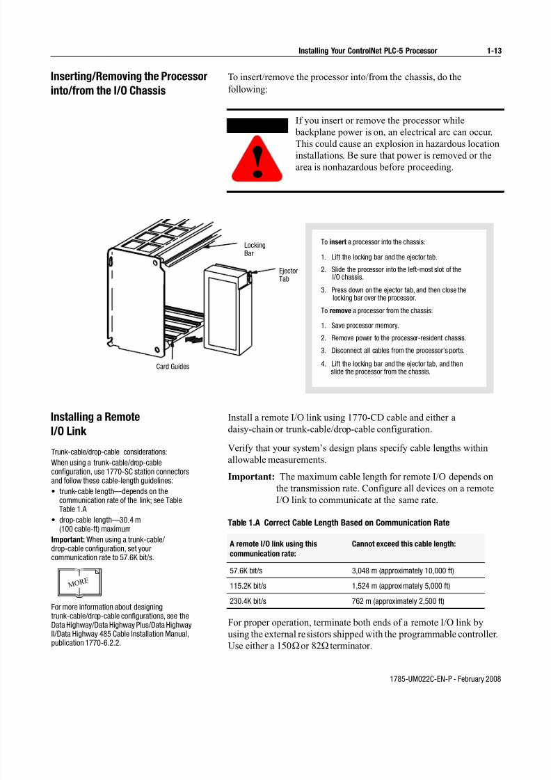
Inserting/Removing the Processor
into/from the I/O Chassis
To insert/remove the processor into/from the chassis, do the
following:
Installing a Remote
I/O Link
Install a remote I/O link using 1770-CD cable and either a
daisy-chain or trunk-cable/drop-cable configuration.
Verify that your system’s design plans specify cable lengths within
allowable measurements.
Important: The maximum cable length for remote I/O depends on
the transmission rate. Configure all devices on a remote
I/O link to communicate at the same rate.
Table 1.A Correct Cable Length Based on Communication Rate
For proper operation, terminate both ends of a remote I/O link by
using the external resistors shipped with the programmable controller.
Use either a 150Ωor 82Ω terminator.
If you insert or remove the processor while
backplane power is on, an electrical arc can occur.This could cause an explosion in hazardous location
installations. Be sure that power is removed or the
area is nonhazardous before proceeding.
WARNING
!
To insert a processor into the chassis:
1. Lift the locking bar and the ejector tab.
2. Slide the processor into the left-most slot of theI/O chassis.
3. Press down on the ejector tab, and then close thelocking bar over the processor.
To remove a processor from the chassis:
1. Save processor memory.
2. Remove power to the processor-resident chassis.
3. Disconnect all cables from the processor's ports.
4. Lift the locking bar and the ejector tab, and thenslide the processor from the chassis.
EjectorTab
LockingBar
Card Guides
Trunk-cable/drop-cable considerations:
When using a trunk-cable/drop-cableconfiguration, use 1770-SC station connectorsand follow these cable-length guidelines:
• trunk-cable length—depends on thecommunication rate of the link; see TableTable 1.A
• drop-cable length—30.4 m(100 cable-ft) maximum
Important: When using a trunk-cable/
drop-cable configuration, set yourcommunication rate to 57.6K bit/s.
For more information about designingtrunk-cable/drop-cable configurations, see theData Highway/Data Highway Plus/Data HighwayII/Data Highway 485 Cable Installation Manual,publication 1770-6.2.2.
M O R E
A remote I/O link using thiscommunication rate:
Cannot exceed this cable length:
57.6K bit/s 3,048 m (approximately 10,000 ft)
115.2K bit/s 1,524 m (approximately 5,000 ft)
230.4K bit/s 762 m (approximately 2,500 ft)

7/27/2019 ControlNet PLC-5 Programmable Controllers User Manual
http://slidepdf.com/reader/full/controlnet-plc-5-programmable-controllers-user-manual 26/148
1785-UM022C-EN-P - February 2008
1-14 Installing Your ControlNet PLC-5 Processor
If your remote I/O link:
Use this
resistor
rating:
The maximum number of
physical devices
that you can connect
on the link is:
logical rack
numbers that you
can scan on the
link is:
Operates at 230.4K bit/s
82Ω 32 16
Operates at 57.6K or 115.2K bit/s, and no devices listed below are linked
Scanners 1771-SN; 1772-SD, -SD2;1775-SR, -S4A, -S4B;6008-SQH1, -SQH2
Adapters 1771-AS; 1771-ASB (Series A Only); 1771-DCM
Miscellaneous 1771-AF
Connects to any device listed below:
Scanners 1771-SN; 1772-SD, -SD2;1775-SR, -S4A, -S4B;6008-SQH1, -SQH2
Adapters 1771-AS; 1771-ASB (Series A Only); 1771-DCM
Miscellaneous 1771-AF
150Ω 16 16
Operates at 57.6K or 115.2K bit/s, and you do not require over 16 physical devices
You can install a remote I/O link two ways:
- trunk cable/drop cable--from the drop cable to the connector screw terminals on the remote I/O connectors of the processor- daisy chain--to the connector screw terminals on the remote I/O connectors of the processor and then to the remote I/O screw terminals of the next remote
I/O device
To connect remote I/O cable, use the Phoenix MTSB2.5/3-ST 3-pin header connector provided in the accessory kit.
1. Run the 1770-CD cable from the processorto each remote I/O adapter module or processor
in the remote I/O system.
2. Connect the signal conductor with blueinsulation to the 3-pin connector terminal
labeled 1 on the processor and to eachremote I/O adapter module (or PLC-5adapter) in the remote I/O system.
3. Connect the shield drain wire to the centerterminal of the 3-pin connector.
4. Connect the signal conductor with clearinsulation to the 3-pin connector terminal
labeled 2.
5. Tie-wrap the remote I/O network cable tothe chassis to relieve strain on the cable.
6. Terminate the remote I/O link by connecting
an external terminator resistor between theremote I/O terminals labeled 1 and 2.
1770-CD
BlueShield
Clear
Shield
Clear
Blue
1770-CD
To another I/Olink device
PLC-5/40C, -5/46C,-5/80C Processor
PLC-5/20CProcessor
82W or150W
resistor
Terminate both ends of a remote I/O link

7/27/2019 ControlNet PLC-5 Programmable Controllers User Manual
http://slidepdf.com/reader/full/controlnet-plc-5-programmable-controllers-user-manual 27/148
1785-UM022C-EN-P - February 2008
Installing Your ControlNet PLC-5 Processor 1-15
Installing a DH+ Link Use 1770-CD cable to connect the processor to a DH+ link.
Follow these guidelines while installing DH+ communication links:
• do not exceed these cable lengths:
– trunk-cable length—3,048 m (approximately 10,000 cable-ft)
– drop-cable length—30.4 m (approximately 100 cable-ft)
• do not connect more than 64 stations on a single DH+ link
If you connect or disconnect the 1770-CD cable with
power applied to this processor or the device on the
other end of the cable, an electrical arc can occur.
This could cause an explosion in hazardous location
installations. Be sure that power is removed or the
area is nonhazardous before proceeding.
When used in a Class I, Division 2, hazardous
location, this equipment must be mounted in a
suitable enclosure with proper wiring method that
complies with the governing electrical codes.
WARNING
! WARNING
!

7/27/2019 ControlNet PLC-5 Programmable Controllers User Manual
http://slidepdf.com/reader/full/controlnet-plc-5-programmable-controllers-user-manual 28/148
1785-UM022C-EN-P - February 2008
1-16 Installing Your ControlNet PLC-5 Processor
If you connect or disconnect the 1770-CD cable with
power applied to this processor or the device on the
other end of the cable, an electrical arc can occur.
This could cause an explosion in hazardous location
installations. Be sure that power is removed or the
area is nonhazardous before proceeding.
When used in a Class I, Division 2, hazardous
location, this equipment must be mounted in a
suitable enclosure with proper wiring method that
complies with the governing electrical codes.
Use the 3-pin connector on the processor toconnect a DH+ link. The connector’s port must
be configured to support a DH+communication link.
You can install a DH+ link two ways:
- trunk cable/drop cable--from the drop cableto the connector screw terminals on the DH+connectors of the processor.
- daisy chain--to the connector screw terminalson the DH+ connectors of the processor.
To make connections, use the Phoenix connectorMTSB2.5/3-ST 3-pin header connector provided
in the accessory kit.
1. Connect the signal conductor with clear
insulation to the 3-pin connector terminal 1at each end of each cable segment.
2. Connect the shield drain wire to the centerterminal of the 3-pin connector at both ends
of each cable segment.
3. Connect the signal conductor with blueinsulation to the 3-pin connector terminal 2
at each end of each cable segment.
82W or 150W resistor 82W or 150W resistor
PLC-5/40C, -5/46Cor -5/80C processor
PLC-520Cprocessor
Clear
Shield
Blue
Clear
Shield
Blue
WARNING
!
WARNING
!

7/27/2019 ControlNet PLC-5 Programmable Controllers User Manual
http://slidepdf.com/reader/full/controlnet-plc-5-programmable-controllers-user-manual 29/148
1785-UM022C-EN-P - February 2008
Installing Your ControlNet PLC-5 Processor 1-17
CH 0
BATT
CH 0
Connecting to a
ControlNet Network
Connect a ControlNet PLC-5 processor to a ControlNet network via a
tap with a 1-m (39.4-in) drop cable.
Four taps are available from Rockwell Automation:
Important: ControlNet taps contain passive electronics and must be
purchased from Rockwell Automation for the network to
function properly.
After terminating your segments, you connect your node to the
network.
If you connect or disconnect the ControlNet tap cable
with power applied to this processor or the device onthe other end of the cable, an electrical arc can occur.
This could cause an explosion in hazardous location
installations. Be sure that power is removed or the
area is nonhazardous before proceeding.
When used in a Class I, Division 2, hazardous
location, this equipment must be mounted in a
suitable enclosure with proper wiring method that
complies with the governing electrical codes.
WARNING
!
WARNING
!
Straight T-tap
1786-TPS
Straight Y-tap
1786-TPYS
Right-angle T-tap
1786-TPR
Right-angle Y-tap
1786-TPYR
Remove the tap’s dust cap – located on the straight or
right-angle connector – and set it aside.
If your network supports:
Connect the tap’s straight orright-angle connector:
nonredundant media to the channel A connector on the
processor – channel B is not used1
redundant media • from trunk-cable A to channel A on the processor
and
• from trunk-cable B to channel B on the processor
1 Rockwell Automation recommends using channel A fornonredundant media.
Nonredundant Media A A
B
Redundant Media

7/27/2019 ControlNet PLC-5 Programmable Controllers User Manual
http://slidepdf.com/reader/full/controlnet-plc-5-programmable-controllers-user-manual 30/148
1785-UM022C-EN-P - February 2008
1-18 Installing Your ControlNet PLC-5 Processor
For detailed information about planning and installing your
ControlNet system, see the following publications:
To view or order these publications online, visit:
http://literature.rockwellautomation.com
Publication Publication Number
ControlNet Cable System Component List AG-2.2
ControlNet Cable System Planning and Installation Manual 1786-6.2.1
ControlNet Network Access Cable Installation Instructions 1786-2.6
ControlNet Fiber Planning and Installation Guide CNET-IN001A-EN-P
System Design for Control of Electrical Noise GMC-RM001A-EN-P
Industrial Automation Wiring and Grounding Guidelines 1770-4.1
Terminating Your ControlNet Coaxial Cables CD-ROM CNET-DM001A-EN-C

7/27/2019 ControlNet PLC-5 Programmable Controllers User Manual
http://slidepdf.com/reader/full/controlnet-plc-5-programmable-controllers-user-manual 31/148
1785-UM022C-EN-P - February 2008
Installing Your ControlNet PLC-5 Processor 1-19
Connecting a
Programming Terminal
You can connect a programming terminal to a ControlNet PLC-5
processor via a:
• DH+ connection
• serial channel
• ControlNet connection
DH+ Connection
To attach a personal computer to a ControlNet PLC-5 processor using
a DH+ connection:
When used in a Class I, Division 2, hazardous
location, this equipment must be mounted in a
suitable enclosure with proper wiring method that
complies with the governing electrical codes.
If you connect or disconnect the DH+ cable with
power applied to this processor or the device on theother end of the cable, an electrical arc can occur.
This could cause an explosion in hazardous location
installations. Be sure that power is removed or the
area is nonhazardous before proceeding.
WARNING
!
WARNING
!
CH 0
Personal computerPLC-5/20CProcessorDH+ Link
Personal computer
DH+ Link
PLC-5/40C, -5/46C,
-5/80C Processor
8-pin
mini-DIN
connector8-pin
mini-DIN
connector

7/27/2019 ControlNet PLC-5 Programmable Controllers User Manual
http://slidepdf.com/reader/full/controlnet-plc-5-programmable-controllers-user-manual 32/148
1785-UM022C-EN-P - February 2008
1-20 Installing Your ControlNet PLC-5 Processor
Serial Channel
To program the processor using Channel 0, configure the channel for
RS-232C using DF1 point-to-point protocol.
When using this
communication card:Use this cable:
1784-KTX , KTX D • 1784-CP13
1784-PCMK • 1784-PCM6
• 1784-PCM5 with 1784-CP7 adapter
1784-PKTX, -PKTXD • 1784-CP13
If your personal computerhas a 9-pin serial port,
use the 1784-CP10 cable.
If your personal computer
has a 25-pin serial port,use the 1784-CP11 cable.
Personal computer Personal computer
PLC-5/20C
Processor
PLC-5/40C, -5/46C
or -5/80 C Processor
If you connect or disconnect the serial cable with
power applied to this processor or the device on the
other end of the cable, an electrical arc can occur.
This could cause an explosion in hazardous location
installations. Be sure that power is removed or the
area is nonhazardous before proceeding.
WARNING
!

7/27/2019 ControlNet PLC-5 Programmable Controllers User Manual
http://slidepdf.com/reader/full/controlnet-plc-5-programmable-controllers-user-manual 33/148
1785-UM022C-EN-P - February 2008
Installing Your ControlNet PLC-5 Processor 1-21
ControlNet Connection
You can connect programming devices to a ControlNet network
through:
• the ControlNet network access cable (1786-CP)
• the ControlNet 1784-PCC1 cable
• a tap on a ControlNet network
Important: Use the 1786-CP cable when connecting a programming
terminal to the network through a NAP. Using a commercially
available RJ-style cable could result in network failure.
ATTENTION: Do not connect the samecommunication card to both the NAP anda tap on the ControlNet network.
!
Personal computer or
other serial device
and your HMI or
programming software
Serial connection
1770-KFC15
Interface
ControlNet Network**
1794-ACNR15
Flex I/O Adapter
1771-ACNR15
Adapter
Data Highway Plus link
Remote I/O link
PLC-5/40C
Examples of ControlNet Connection Types
Personal computer
with 1784-KTCX15 card
(ISA-based) and
your HMI or
programming software
Laptop computer with
1784-PCC card (PCMCIA-based)
and your HMI or
programming software
PLC-5/40C
1784-PCC1 to PLC-5 (NAP
port or any other NAP port)*
Personal computer
with PCIC card (PCI-based)
and your HMI
or programming software
Tap (4 choices)
1786-TPR
1747-ACNR15
Adapter
Tap (4 choices)
1786-TPR
*A programming terminal connected through this cable is counted as a node and must have a unique address.
**Redundant media not required.
1794-ACNR15
FLEX I/O Adapter
If you connect or disconnect the ControlNet cable
with power applied to this processor or the device on
the other end of the cable, an electrical arc can occur.
This could cause an explosion in hazardous location
installations. Be sure that power is removed or the
area is nonhazardous before proceeding.
WARNING
!

7/27/2019 ControlNet PLC-5 Programmable Controllers User Manual
http://slidepdf.com/reader/full/controlnet-plc-5-programmable-controllers-user-manual 34/148
1785-UM022C-EN-P - February 2008
1-22 Installing Your ControlNet PLC-5 Processor
Selecting Appropriate Cables This section lists information about:
• serial cables
• DH+ programming cables
• remote I/O cables
• ControlNet cables
For more information about cables, see the Enhanced and Ethernet
PLC-5 Programmable Controllers User Manual, publication
1785-6.5.12.
Serial Cables
You can make your own serial cables or purchase them from
Rockwell Automation.
The side label of the processor shows the following table, which
lists Channel 0 (serial port) pin assignments.
When used in a Class I, Division 2, hazardous
location, this equipment must be mounted in a
suitable enclosure with proper wiring method that
complies with the governing electrical codes.
WARNING
!
Pin RS-232C RS-422A RS-423 Pin RS-232C RS-422A RS-423
1 C.GND C.GND C.GND 14 NOT USEDTXD.OUT
- SEND COM
2 TXD.OUT TXD.OUT+ TXD.OUT 15
3 RXD.IN RXD.IN+ RXD.IN 16 NOT USEDRXD.IN
- REC COM
4 RTS.OUT RTS.OUT+ RTS.OUT 17
5 CTS.IN CTS.IN+ CTS.IN 18
6 DSR.IN DSR.IN+ DSR.IN 19 NOT USEDRTS.OUT
- NOT USED
7 SIG.GND SIG.GND SIG.GND 20 DTR.OUT DTR.OUT+ DTR.OUT
8 DCD.IN DCD.IN+ DCD.IN 21
9 22 NOT USED DSR.IN- NOT USED
10 NOT USEDDCD.IN
- NOT USED 23 NOT USEDDTR.OUT
- NOT USED
11 24
12 25
13 NOT USEDCTS.IN
- NOT USED
The shading indicates that the pin is reserved.

7/27/2019 ControlNet PLC-5 Programmable Controllers User Manual
http://slidepdf.com/reader/full/controlnet-plc-5-programmable-controllers-user-manual 35/148
1785-UM022C-EN-P - February 2008
Installing Your ControlNet PLC-5 Processor 1-23
This processor’s serial port can support these configurations:
Important: Follow these guidelines:
• When Channel 0 is configured for RS-422A compatibility, do notuse terminating resistors anywhere on the link.
• When Channel 0 is configured for RS-422A (compatible) and RS-423, do not go beyond 61 m (approximately 200 ft). Thisdistance restriction is independent of the transmission rate.
DH+ Programming Cables
Remote I/O Cables
Use 1770-CD or cable for remote I/O. See Inser ting/Removing the
Processor into/from the I/O Chassis on page 1-13 for more
information.
ControlNet Cables
Several types of RG-6 quad-shield cable may be appropriate for your
ControlNet installation—depending on the environmental factors
associated with your application and installation site.
Digital Interface Maximum Cable Length
RS-232C 15 m (approximately 50 ft)
RS-422A (compatible) 61 m (approximately 200 ft)
RS-423 61 m (approximately 200 ft)
When using this
communication card:Use this cable:
1784-KTX , KTX D • 1784-CP13
1784-PCMK • 1784-PCM6
• 1784-PCM5 with 1784-CP7 adapter
1784-PKTX, -PKTXD • 1784-CP13

7/27/2019 ControlNet PLC-5 Programmable Controllers User Manual
http://slidepdf.com/reader/full/controlnet-plc-5-programmable-controllers-user-manual 36/148
1785-UM022C-EN-P - February 2008
1-24 Installing Your ControlNet PLC-5 Processor
The following ControlNet cable system components are available
from the Rockwell Automation:
Important: Install all wiring for your ControlNet system in
accordance with the regulations contained in the
National Electric Code (or applicable country codes),
state codes, and applicable municipal codes.
Item1 Cat. No.
ControlNet Coax Tool Kit 1786-CTK
Coax Tap Kit Right-angle T-tap 1786-TPR
Straight T-tap 1786-TPS
Right-angle Y-tap 1786-TPYR
Straight Y-tap 1786-TPYS
Repeaters Repeater adapter 1786-RPA
Copper 1786-RPCD
Fiber -short 1786-RPFS
Fiber - medium 1786-RPFM
Fiber ring - long 21786-RPFRL
Fiber ring - extra long 21786-RPFRXL
Dummy load 1786-TCAP
Fiberoptic Repeaters Low-voltage dc 1786-RPA
RG-6 Quad Shield Cable Standard-PVC CM-CL2 1786-RG6
ControlNet Network Access Cable—3.05 m (10 ft) 1786-CP
PC Card Cable for 1784-PCC 1784-PCC1
BNC Connectors Barrel (plug to plug) 1786-BNCP
BNC/RG-6 plug 1786-BNC
Bullet (jack to jack) 1786-BNCJ
Isolated-bulkhead (jack to jack)
1786-BNCJI
Terminators (BNC-75Ω) 1786-XT
1 For a complete list of ControlNet cable system components that are available fromRockwell Automation and other sources, see the ControlNet Cable SystemComponent List, publication AG-2.2.
2 Planned availability - March 2002.

7/27/2019 ControlNet PLC-5 Programmable Controllers User Manual
http://slidepdf.com/reader/full/controlnet-plc-5-programmable-controllers-user-manual 37/148
1785-UM022C-EN-P - February 2008
Installing Your ControlNet PLC-5 Processor 1-25
For detailed information about ControlNet cabling, see the following
publications:
Publication Publication Number
ControlNet Cable System Component List AG-2.2
ControlNet Cable System Planning and Installation Manual 1786-6.2.1
ControlNet Network Access Cable Installation Instructions 1786-2.6
ControlNet System Overview 1786-2.9
ControlNet Fiber Planning and Installation Guide CNET-IN001A-EN-P
System Design for Control of Electrical Noise GMC-RM001A-EN-P
Industrial Automation Wiring and Grounding Guidelines 1770-4.1
Terminating Your ControlNet Coaxial Cable CNET-DM001A-EN-C

7/27/2019 ControlNet PLC-5 Programmable Controllers User Manual
http://slidepdf.com/reader/full/controlnet-plc-5-programmable-controllers-user-manual 38/148
1785-UM022C-EN-P - February 2008
1-26 Installing Your ControlNet PLC-5 Processor
Notes

7/27/2019 ControlNet PLC-5 Programmable Controllers User Manual
http://slidepdf.com/reader/full/controlnet-plc-5-programmable-controllers-user-manual 39/148
1785-UM022C-EN-P - February 2008
Chapter 2
Planning to Use Your ControlNet PLC-5
Processor Using This Chapter
To distinguish phase 1.5 ControlNet processors from earlier phase
processors, new catalog numbers were created for each of the phase
1.5 ControlNet processors: 1785-L20C15, 1785-L40C15, L46C15,
and 1785-L80C15.
Understanding
ControlNet I/O
The ControlNet system is designed to:
• provide high-speed, repeatable, deterministic I/O transmission• allow control and message information to co-exist on the same
physical media
• make sure that I/O data transfers are not affected by
- programming-terminal message activity
- inter-PLC processor message activity on the network
Topic Page
Understanding ControlNet I/O 2-1
Understanding Scheduled Connection Types 2-11
Understanding ControlNet I/O mapping 2-16
Using I/O Mapping Techniques 2-21
Using the ControlNet PLC-5 processor in a ControlNet I/O system 2-31
Converting from a non-ControlNet remote I/O system to aControlNet I/O system
2-34
Converting from ControlNet phase 1.0 or 1.25 to ControlNetphase 1.5
2-35
You cannot mix phase 1.5 and earlier phase (such as
1.0 and 1.25) products on the same ControlNet
network.
ATTENTION
!

7/27/2019 ControlNet PLC-5 Programmable Controllers User Manual
http://slidepdf.com/reader/full/controlnet-plc-5-programmable-controllers-user-manual 40/148
1785-UM022C-EN-P - February 2008
2-2 Planning to Use Your ControlNet PLC-5 Processor
Scheduled Data-Transfer Operations on a ControlNet Network
ControlNet scheduled data transfer on a ControlNet PLC-5 processor:
• is continuous
• is asynchronous to the ladder-logic program scan
• occurs at the actual rate displayed in the Actual Packet Interval(API) field on the programming software scanlist configurationscreen in RSNetWorx for ControlNet software
Important: The Requested Packet Interval (RPI) rate requested for a
connection establishes the data transfer rate on the ControlNet
network. API is determined by RSNetWorx software when the
schedule is built. The API will always be the same or less than the
RPI.
The API does not imply the actual I/O throughput. I/O data is sent on
the network every API regardless of whether the I/O data has been
refreshed with newer I/O data. I/O throughput time may be slower due to delays caused by module update times, processor scan times
and adapter to I/O module transfer times.
Data from the output-image file is put into
a private memory buffer. New output data
may stay in the data table files up to 1
program scan or until the next housekeeping.
Scheduled data transfer
occurs between the PLC-5
and the adapter module in
the I/O chassis. Data may
stay in the private memory
buffer for up to 1 API.
In the same manner,
the I/O adapter has
scheduled I/O data
transfer with I/O
modules
Output data is written from a private
memory buffer on the adapter to the
module. The output data stays in
the private memory buffer for as long
as it takes the I/O chassis backplane
update to occur.
In scheduled I/O data
transfer, updates occur
between logic scans
(i.e. during
"housekeeping")
Logic Scan
Housekeeping
Data
Table
Files
Private
Memory
Buffers
Private
Memory
Buffers
Scheduled Data
Transfer Data Update
PLC-5 Programmable Controller
Adapter Module I/O Modules
Program Scan
Data Update
I/O Chassis
1 2 3
What Happens During Scheduled Output Data Transfer
7/27/2019 ControlNet PLC-5 Programmable Controllers User Manual
http://slidepdf.com/reader/full/controlnet-plc-5-programmable-controllers-user-manual 41/148
1785-UM022C-EN-P - February 2008
Planning to Use Your ControlNet PLC-5 Processor 2-3
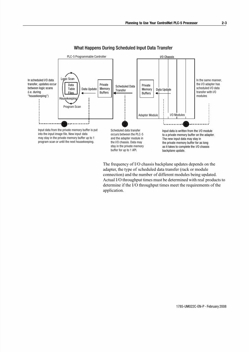
The frequency of I/O chassis backplane updates depends on the
adapter, the type of scheduled data transfer (rack or module
connection) and the number of different modules being updated.
Actual I/O throughput times must be determined with real products to
determine if the I/O throughput times meet the requirements of theapplication.
Input data from the private memory buffer is put
into the input image file. New input data
may stay in the private memory buffer up to 1
program scan or until the next housekeeping.
Scheduled data transfer
occurs between the PLC-5
and the adapter module in
the I/O chassis. Data may
stay in the private memory
buffer for up to 1 API.
In the same manner,
the I/O adapter has
scheduled I/O data
transfer with I/O
modules
Input data is written from the I/O module
to a private memory buffer on the adapter.
The new input data may stay in
the private memory buffer for as long
as it takes to complete the I/O chassis
backplane update.
In scheduled I/O data
transfer, updates occur
between logic scans
(i.e. during
"housekeeping")
Logic Scan
Housekeeping
Data
Table
Files
Private
Memory
Buffers
Private
Memory
Buffers
Scheduled Data
Transfer Data Update
PLC-5 Programmable Controller
Adapter Module I/O Modules
Program Scan
Data Update
I/O Chassis
123
What Happens During Scheduled Input Data Transfer

7/27/2019 ControlNet PLC-5 Programmable Controllers User Manual
http://slidepdf.com/reader/full/controlnet-plc-5-programmable-controllers-user-manual 42/148
1785-UM022C-EN-P - February 2008
2-4 Planning to Use Your ControlNet PLC-5 Processor
The following scheduled data-transfer operations are supported by the
ControlNet processors on a ControlNet network:
Table 2.A ControlNet Scheduled Data-Transfer Operations
Unscheduled Data-Transfer Operations on a ControlNet Network
The ControlNet network allows you to use unscheduled messaging
when deterministic delivery is not required. Unscheduled operations
include:
• unscheduled I/O data transfers, or when unscheduled messagingis event-driven—through ControlNet I/O Transfer (CIO)instructions
• peer-to-peer messaging—through Message (MSG) instructions
• messaging from programming devices
• messaging from Human Machine Interface (HMI) devices
Operation Description
Discrete I/O DataTransfer (can be doneas a rack or moduleconnection)
Performed in a deterministic and repeatable mannerasynchronous to and independent of the ladder-logicprogram scan. You configure all ControlNet discrete I/Odata transfers on a per-node basis in the I/O map table
(scanlist configuration).1
Non-discrete I/O Data Transfer (can be doneas a moduleconnection)
Handled with the same priority as discrete I/O datatransfer. You can update analog data without usingblock-transfer instructions in ladder programs. You dothis by including non-discrete I/O data-transferconfigurations in the I/O map table (scanlistconfiguration). This data is updated in the buffers anddata-table files between logic scans in the same
manner as that used in discrete I/O data transfer.1
Peer-to-peerCommunication
Allows a ControlNet processor to communicate withany other ControlNet processor on the ControlNetnetwork with the same priority as that of the discrete
and non-discrete I/O data transfers discussed above.1
1 While scheduled data transfer is asynchronous to program scanning, all data ispresented synchronously to and from the user data table during housekeeping.

7/27/2019 ControlNet PLC-5 Programmable Controllers User Manual
http://slidepdf.com/reader/full/controlnet-plc-5-programmable-controllers-user-manual 43/148
1785-UM022C-EN-P - February 2008
Planning to Use Your ControlNet PLC-5 Processor 2-5
The ControlNet system places your scheduled transfers in the first
part of each Network Update Interval (NUI). Time is automatically
reserved for network maintenance. Unscheduled transfers are
performed during the time remaining in the interval.
Unscheduled messaging on a ControlNet network is
non-deterministic. Your application and your configuration—number
of nodes, application program, NUT, amount of scheduled bandwidth
used, etc.—determine how much time there is for unscheduled
messaging.
Important: The ControlNet network reserves time for at least one
maximum-sized unscheduled transfer per NUI.
Depending on how much time there is for unscheduled
messaging, every node may not have a chance to send
unscheduled data every NUI.
You reserve aspecific amountof time for allscheduledoperations
Any time remaining is usedfor unscheduled operations
The systemreserves timefor network maintenance
One occurrence of the NUT is a NUI
. . .. . .

7/27/2019 ControlNet PLC-5 Programmable Controllers User Manual
http://slidepdf.com/reader/full/controlnet-plc-5-programmable-controllers-user-manual 44/148
1785-UM022C-EN-P - February 2008
2-6 Planning to Use Your ControlNet PLC-5 Processor
Table 2.B ControlNet Unscheduled Data-Transfer Operations
Operation Description Features
Non-discrete I/O
Data Transfer
CIO Instructions
Perform ladder-initiated unscheduled non-discrete I/O data transfers ona ControlNet network by using ControlNet I/O Transfer (CIO) instructions.
The data type for these transfers (CT) has the following information:
• Command:
1771 READ reads data from a 1771 non-discreteI/O module
1771 WRITE writes data to a 1771 non-discreteI/O module
1794 READ reads data from a 1794 I/O module
1794 WRITE writes data to a 1794 I/O module
1794 FAULT ACTION changes the action a module takeswhen it faults
1794 IDLE ACTION changes the action a module takeswhen it is idle
1794 CONFIG DATA changes a module’s configuration
data1794 SAFE STATE DATA changes a module’s safe-state data
CIP GENERIC sends user-specified CIP service Generic bi-directional sends user-specified CIP service
which requires reply data 1747 READ INPUT reads data from SLC I/O module
input file
1747 WRITE OUTPUT writes data to SLC I/O module output file
1747 READ M0 FILE reads data from SLC I/O module M0 file
1747 WRITE M0 FILE writes data to SLC I/O module M0
file 1747 READ M1 FILE reads data from SLC I/O module
M1 file
1747 WRITE M1 FILE writes data to SLC I/O module M1 file
1747 SAFE STATE change SLC I/O module safe state DATA data 1747 WRITE FLAGS change action SLC I/O module
take when it faults and/or goes to idle
1747 CONFIG DATA change SLC module’s configuration data
• Data-table address in source processor
• Size of message in words
• Network address of destination node
• Slot of destination module
• Port number—set to 2 for the ControlNet network
• Flags:.TO forces a transfer to time out
.EW indicates that the transfer is waiting for an open connection
.CO transfer is made continuously in Run mode
.ER indicates that the transfer was terminated due to an error
.DN indicates that the transfer was made without error
.ST indicates that the transfer was started
.EN indicates that the transfer instruction is enabled
• Error code—indicates the error when the.ER bit is set 2
• Done length—indicates the number of words transferred
• As many as 32 1771 READ and/or 1771 WRITE
CIOs can be active at a time 1
• Minor fault bit S:17/14 is set when 32 1771READ and/or 1771 WRITE CIOs are active at atime
• As many as a total of 8 1794 FLEX I/O and 1747
SLC I/O CIOs can be active at a time 1
• Minor fault bit S:17/15 is set when 8 1794 FLEXI/O CIOs are active at a time
• Any transfer initiated from a Processor InputInterrupt (PII) or Selectable Timed Interrupt (STI)program suspends execution of the programscan until the transfer is completed
Important: This can extend your program scanby tens of milliseconds.
• No transfer is initiated when the processor is inProgram mode
• Transfers that have been running with the.CObit set automatically restart on theProgram-to-Run transition when the ContinueLast step bit is set and the data table has notchanged
• A transfer has a maximum size of 64 words
• If the SFC startover bit is set in the processorconfiguration file, continuous CIOs may time outif you cycle power in RUN mode. If this happens,the CIO error bit is set. To reset the error bit, theCIO instruction rung condition must go fromFALSE to TRUE.
See Chapter 4 and Appendices C and F for more
information.

7/27/2019 ControlNet PLC-5 Programmable Controllers User Manual
http://slidepdf.com/reader/full/controlnet-plc-5-programmable-controllers-user-manual 45/148
1785-UM022C-EN-P - February 2008
Planning to Use Your ControlNet PLC-5 Processor 2-7
Using I/O Forcing Operations
ControlNet I/O forcing occurs in the same way as remote I/O forcing
in the ControlNet processors. The processor performs the forcing and
transmits the forced data to the output- and input-image tables. You
can force any discrete I/O data placed in the I/O image; however,
forcing of DIF and DOF data is not supported.
For detailed information about forcing, see your programming
software documentation.
Peer-to-peer
Messaging
MSG Instructions
You can use ControlNet message (MSG) instructions and the data-typeMG to create unscheduled messages that are initiated by one ControlNetPLC-5 processor and sent to another ControlNet PLC-5 processor. TheMG data type for the ControlNet instruction has the following
information:• Command—PLC-5 TYPED READ, PLC-5 TYPED WRITE, PLC-3 WORD
RANGE READ, PLC-3 WORD RANGE WRITE, PLC-2 UNPROTECTEDREAD, PLC-2 UNPROTECTED WRITE
• Data-table address in source processor
• Size of message in elements
• Network address of destination processor
• Data-table address in destination processor
• Port number—set to 2 for the ControlNet network
• Flags:
.TO forces a message to time out
.EW indicates that the message is waiting for an open connection
.CO message is sent continuously in Run mode
.ER indicates that the message was terminated due to an error
.DN indicates that the message was sent without error
.ST indicates that the message was started
.EN indicates that the message instruction is enabled
.NC forces the connection to close when the message is done
• Error code—indicates the error when the.ER bit is set 2
• As many as 32 ControlNet MSGs can be active
at a time 1
• Minor fault bit S:17/13 is set when 32ControlNet MSGs are active at a time
• All messages have the same priority
• No message is initiated when the processor isin Program mode
• Messages that have been running with the.CObit set automatically restart on the Program-to-Run transition when the Continue Last stepbit is set and the data table has not changed
• Each message has a maximum size of 1000elements
See chapter 4 and Appendices C and F for moreinformation.
1 Because connections are opened and closed as needed, more can exist in a program as long as no more than this number are active at one time.2 See Appendix D for a list of ControlNet error codes.
Operation Description Features

7/27/2019 ControlNet PLC-5 Programmable Controllers User Manual
http://slidepdf.com/reader/full/controlnet-plc-5-programmable-controllers-user-manual 46/148
1785-UM022C-EN-P - February 2008
2-8 Planning to Use Your ControlNet PLC-5 Processor
Using Immediate Data-Transfer Operations
ControlNet Immediate Data I/O transfers—Immediate Data Input
(IDI) and Immediate Data Output (IDO)—perform similarly to the
Remote-I/O supported immediate I/O transfers—Immediate Input
(IIN) and Immediate Output (IOT)—which the ControlNet system
also supports. The logic scan is temporarily interrupted while the
most recent state of up to 64 words is read from or written to the
private memory buffer.
ControlNet Data Transfer
PrivateMemory
Buffers
H o u s e k e e p i n g
L o g i c
S c a n
Program Scan
Data-Table
Files
Immediate Data Transfer
= Unscheduled Data Transfer
= Scheduled Data Transfer= NUI
Data Update
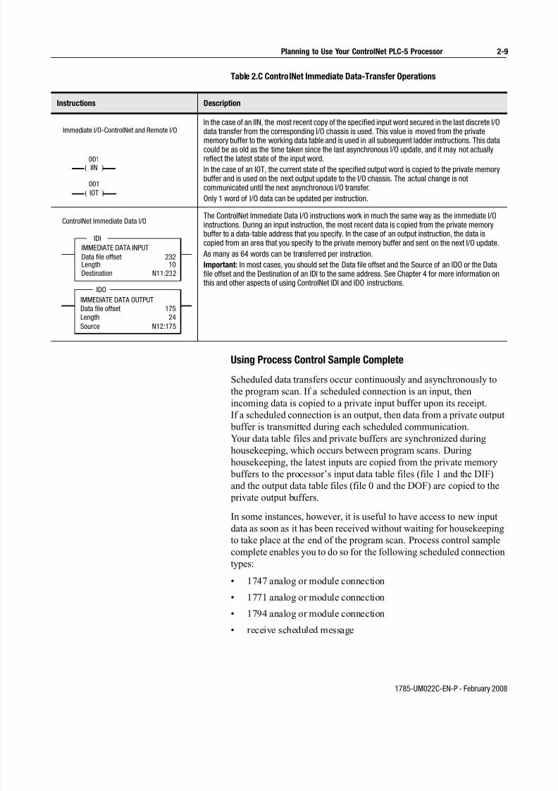
7/27/2019 ControlNet PLC-5 Programmable Controllers User Manual
http://slidepdf.com/reader/full/controlnet-plc-5-programmable-controllers-user-manual 47/148
1785-UM022C-EN-P - February 2008
Planning to Use Your ControlNet PLC-5 Processor 2-9
Table 2.C ControlNet Immediate Data-Transfer Operations
Using Process Control Sample Complete
Scheduled data transfers occur continuously and asynchronously to
the program scan. If a scheduled connection is an input, then
incoming data is copied to a private input buffer upon its receipt.
If a scheduled connection is an output, then data from a private output buffer is transmitted during each scheduled communication.
Your data table files and private buffers are synchronized during
housekeeping, which occurs between program scans. During
housekeeping, the latest inputs are copied from the private memory
buffers to the processor’s input data table files (file 1 and the DIF)
and the output data table files (file 0 and the DOF) are copied to the
private output buffers.
In some instances, however, it is useful to have access to new input
data as soon as it has been received without waiting for housekeeping
to take place at the end of the program scan. Process control sample
complete enables you to do so for the following scheduled connectiontypes:
• 1747 analog or module connection
• 1771 analog or module connection
• 1794 analog or module connection
• receive scheduled message
Instructions Description
In the case of an IIN, the most recent copy of the specified input word secured in the last discrete I/Odata transfer from the corresponding I/O chassis is used. This value is moved from the private
memory buffer to the working data table and is used in all subsequent ladder instructions. This datacould be as old as the time taken since the last asynchronous I/O update, and it may not actuallyreflect the latest state of the input word.
In the case of an IOT, the current state of the specified output word is copied to the private memorybuffer and is used on the next output update to the I/O chassis. The actual change is notcommunicated until the next asynchronous I/O transfer.
Only 1 word of I/O data can be updated per instruction.
The ControlNet Immediate Data I/O instructions work in much the same way as the immediate I/Oinstructions. During an input instruction, the most recent data is copied from the private memorybuffer to a data-table address that you specify. In the case of an output instruction, the data iscopied from an area that you specify to the private memory buffer and sent on the next I/O update.
As many as 64 words can be transferred per instruction.
Important: In most cases, you should set the Data file offset and the Source of an IDO or the Data
file offset and the Destination of an IDI to the same address. See Chapter 4 for more information onthis and other aspects of using ControlNet IDI and IDO instructions.
Immediate I/O-ControlNet and Remote I/O
001
( )IIN
001
( )IOT
ControlNet Immediate Data I/O
IDI
IMMEDIATE DATA INPUT
Data file offsetLength
23210
Destination N11:232
IDO
IMMEDIATE DATA OUTPUT
Data file offset
Length
175
24
Source N12:175

7/27/2019 ControlNet PLC-5 Programmable Controllers User Manual
http://slidepdf.com/reader/full/controlnet-plc-5-programmable-controllers-user-manual 48/148
1785-UM022C-EN-P - February 2008
2-10 Planning to Use Your ControlNet PLC-5 Processor
You enable process control sample complete on a per connection
basis by setting the PCSC enable bit in the connection’s ControlNet
I/O status file entry.
When process control sample complete is enabled for a connection
and the processor is in RUN mode, newly received data for that
connection is immediately copied into your data table (even if the
processor is in the middle of a program scan) and the PCSC new data
bit is set in the connection’s ControlNet I/O status file entry. This data
will not be updated again during a program scan until you clear the
PCSC new data bit. The data is updated during housekeeping,
regardless of the state of the new data bit.
If new data is received and the PCSC new data bit is already set, then
the PCSC overflow bit is set. In this event, your data table will not be
updated. Process control sample complete uses bits 2, 3, and 4 of the
first word of the ControlNet I/O status file entry. See Appendix D for
more information about the ControlNet I/O status file.
The input data must be mapped into the DIF. PCSC is not enabled if
the input data is mapped into the discrete input image table.
0000102003040500607080091011120131415
First Word
PCSC Overflow Bit
PCSC New Data Bit
PCSC Enable Bit
Bit Description
2—PCSC Enable When this bit is set, the processor updates your ControlNet data input file when new data is received. Processcontrol sample complete can be dynamically enabled and disabled by your program during a program scan. This canbe done by setting and clearing the PCSC enable bit of the connection’s entry in the ControlNet status file. After thisbit has been set, the input data should not be read until the PCSC new data bit has been set by the processor.
3—PCSC New Data This bit is set by the processor when the PCSC enable bit is set to one and new data has been copied to theControlNet data input file. To insure that you do not access this data while the processor is copying new data to thedata input file, do not access the data until the PCSC new data bit has been set by the system.
When this bit is set to one, it signifies that new data has been received and it is safe to read from your ControlNetdata input file. This data is not updated again until you clear this bit or until housekeeping occurs between program
scans.Never set this bit to one.
4—PCSC Overflow This bit indicates that your program is not checking the PCSC new data bit often enough to use all processor controlsample complete data that has arrived. If the PCSC new data bit has not been cleared by the time a new data samplearrives, the PCSC overflow bit is set and the new data is not copied to the ControlNet data input file.
You must clear this bit. If you clear the PCSC New Data bit but not the PCSC overflow bit, the ControlNet data inputfile is still updated when the next process control sample complete data is received.
Never set this bit to one.

7/27/2019 ControlNet PLC-5 Programmable Controllers User Manual
http://slidepdf.com/reader/full/controlnet-plc-5-programmable-controllers-user-manual 49/148
1785-UM022C-EN-P - February 2008
Planning to Use Your ControlNet PLC-5 Processor 2-11
Clearing the PCSC New Data and PCSC Overflow Bits
If it is crucial to maintain the integrity of the PCSC overflow bit after
new data has arrived while clearing the PCSC new data and overflow
bits. Then do the following:
1. Disable process control sample complete by setting the PCSCenable bit for the connection to zero.
When process control sample complete is disabled, the system
will not modify the new data and overflow bits while you clear
them.
2. Clear the PCSC new data and the PCSC overflow bits.
3. Re-enable process control sample complete by setting the
connection’s PCSC enable bit back to one.
Considerations When Using PCSC
When using scheduled ControlNet 1.5 communications to analog I/O
(such as map entries) and you are using the PID instruction in the
PLC-5/15, then you should do the following:
• the analog module must be set up to use RTS (Real Time Sample)mode
• set your analog RPI (Repetitive Packet Interval) to be at leasttwice the RTS time
• your ladder program needs to set the PCSC enable bit
• your ladder program needs to use the PCSC done bit to conditionthe execution of the PID instruction
• the PID loop update must equal the RTS rate
• your ladder program must use the PCSC overflow bit to takeappropriate action on an overflow condition
Understanding Scheduled
Connection Types
Scheduled connections are made to I/O devices such as I/O adapters
and to peer-to-peer devices such as other controllers.
There are some common scheduled connection types made from the
ControlNet PLC-5 to other Allen-Bradley products that are detailed
in the following section. These scheduled connection types have
certain behaviors and limitations that you must understand before
configuring the connections. The ControlNet PLC-5 can also make
scheduled connections to products not manufactured byAllen-Bradley. Refer to the literature that accompanies those products
for information on their scheduled connection behavior.
Scheduled connection types made from the ControlNet PLC-5 to I/O
adapters can be made either to some or all of the discrete I/O on the
adapter (called a rack connection), or to individual modules (called a
module connection).

7/27/2019 ControlNet PLC-5 Programmable Controllers User Manual
http://slidepdf.com/reader/full/controlnet-plc-5-programmable-controllers-user-manual 50/148
1785-UM022C-EN-P - February 2008
2-12 Planning to Use Your ControlNet PLC-5 Processor
There are four general types of scheduled connections from the
ControlNet PLC-5 to I/O adapters:
• exclusive owner - these scheduled connections indicate thePLC-5 has exclusive ownership of the outputs. These scheduled connections can also gather inputs from the device. There cannot
be more than one exclusive owner connection made to either therack connection or module connection at a time.
• input only - these scheduled connections only gather inputs fromthe I/O adapters. These scheduled connections do not requireother scheduled connection types to be first established before itsscheduled connection can be established.
• listen only - these scheduled connections are similar to input onlyscheduled connections, except that they require a differentscheduled connection to be first established before its connectioncan be established.
• redundant owner - these scheduled connections are similar to
exclusive owner scheduled connections because they both cancontrol outputs and gather inputs. The difference between them isthat with redundant owner scheduled connections, multipleControlNet PLC-5 controllers can establish identical redundantconnections. Only one of the controllers that establish theredundant scheduled connection will own the outputs.
Redundant connections can only be used in a PLC-5 ControlNetHot Backup system. Refer to the PLC-5 ControlNet Hot BackupUser Manual, publication 1785-6.5.24 for more information onusing redundant connections.
Allowable Scheduled Connection Type Combinations for I/O
Adapter Connections
Only specific combinations of scheduled connection types are
allowable. RSNetWorx software will have a pull down list showing
all allowable schedule connection types.
The following details about these combinations assume that different
processors are making either rack connections to the same adapter or
module connections to the same slot.
Important: The 1771-ACN(R15) requires a rack connection to be
established before any module connections are accepted.
If an exclusive owner connection is made to the adapter:• another exclusive owner connection will be rejected
• an input only connection can be made
• a listen only connection can be made
• a redundant owner connection will be rejected

7/27/2019 ControlNet PLC-5 Programmable Controllers User Manual
http://slidepdf.com/reader/full/controlnet-plc-5-programmable-controllers-user-manual 51/148
1785-UM022C-EN-P - February 2008
Planning to Use Your ControlNet PLC-5 Processor 2-13
If an input only connection is made to the adapter:
• an exclusive owner connection can be made
• another input only connection can be made
• a listen only connection can be made
• a redundant owner connection can be made
A listen only connection can only be made to the adapter if:
• an exclusive owner connection already exists, or
• an input only connection already exists, or
• a redundant owner connection already exists
If a redundant owner connection is made to the adapter:
• an exclusive owner connection will be rejected
• an input only connection can be made
• a listen only connection can be made
• another identical redundant owner connection can be made
Multiple Processors Can Control I/O on the Same ControlNet
Link
A processor at any valid node address can control the outputs of a
particular module or rack. However, only one processor can control
the same outputs at any one time.
In the following figure, the processor at node 1 can control the
outputs of node 2 while the processor at node 3 controls the outputs of
node 4.
node 1 node 2 node 3 node 4

7/27/2019 ControlNet PLC-5 Programmable Controllers User Manual
http://slidepdf.com/reader/full/controlnet-plc-5-programmable-controllers-user-manual 52/148
1785-UM022C-EN-P - February 2008
2-14 Planning to Use Your ControlNet PLC-5 Processor
Understanding Multicast Inputs
This feature enables input devices to send the same data to multiple
processors simultaneously.
Advantages of multicast inputs include:
• Network optimization - reduces network usage since data is sent
only once simultaneously to all connections. This reduction may
allow more complex scheduled connection configurations or
improved unscheduled connection performance.
• Device synchronization - inputting data to all devices
simultaneously improves synchronization between devices
In the following example, the ControlNet PLC-5 processor at node 2
is sending outputs to the adapter at node 3. Nodes 1, 2, and 4 are all
receiving the same input packet from node 3. Nodes 1 and 4 areconsidered listen-only and are producing heartbeats to keep their
connections to the adapter alive.
Understanding Multicast Outputs
This feature enables the PLC-5 to simultaneously send the same
output data to more that one target device. To use this feature, both
the PLC-5 and the target devices must support multicast outputs.
Advantages of multicast outputs include:
• Network optimization - reduces network usage since data is sentonly once simultaneously to all connections. This reduction may
allow more complex scheduled connection configurations or
improved unscheduled connection performance.
• Device synchronization - outputting data to all devices
simultaneously improves synchronization between devices
Heartbeat Connection Heartbeat Connection
Point-to-Point Outputs
ControlNet PLC-5
Processor
Node 1
ControlNet PLC-5
Processor
Node 2
ControlNet Adapter
Node 3
ControlNet PLC-5
Processor
Node 4
Multicast Inputs

7/27/2019 ControlNet PLC-5 Programmable Controllers User Manual
http://slidepdf.com/reader/full/controlnet-plc-5-programmable-controllers-user-manual 53/148
1785-UM022C-EN-P - February 2008
Planning to Use Your ControlNet PLC-5 Processor 2-15
Using Multicast Outputs
To use multicast outputs, you must first configure each Multicast
Output connection in RSNetworx 3.0:
1. In the Details Tab of Connection Properties dialog, change the
Scanner to Target Network Connection to Multicast. You cannotmodify this field for any device that does not support multicast
outputs.
2. The Scanner to Target Multicast ID of the Details Tab indicates to
which multicast output group the connection belongs.
All connections with the same Multicast ID will have their output
data combined into a single transmission on the ControlNet
network.
The processor will combine the output data into a single packet
and simultaneously send it to all assigned connections that have
the same:
• Request Packet Interval
• Output Address in the PLC-5 data table
• Output Size
You must determine if the output data being sent to each device of
a multicast group is compatible with the application.
Using Multicast Outputs affects the ControlNet I/O Status file
Immediate Inhibit bit and ControlNet I/O Status file Reset bit
functionality:
• ControlNet I/O Status file Immediate Bit - since all
connections in a Scanner to Target Multicast ID group share the
same output data, the Immediate Inhibit Bit will not take affect
until all connections of that group have their immediate inhibit bit
set. After the immediate inhibit takes place, you may
independently re-enable each connection by clearing this bit.
• ControlNet I/O Status file Reset Bit - all connections of a
Scanner to Target Multicast ID group must have this bit set or
cleared so that the target devices are put into the correct state.
The Reset Bit affects all connections for a given multicast ID
group.

7/27/2019 ControlNet PLC-5 Programmable Controllers User Manual
http://slidepdf.com/reader/full/controlnet-plc-5-programmable-controllers-user-manual 54/148
1785-UM022C-EN-P - February 2008
2-16 Planning to Use Your ControlNet PLC-5 Processor
Understanding ControlNet
I/O Mapping
All scheduled data transfers must be mapped on a ControlNet
network. You specify where I/O data is to be read from or written
to—i.e., mapped. You do this and establish the relationship between
processors, I/O adapters, and data-table file addresses by creating and
maintaining an I/O map table. An I/O map-table entry is required for
each scheduled data transfer. The map table is stored in theconfiguration section of memory and is not accessible by your
application program.
Using your programming software, you can automatically configure
and map nodes attached to your ControlNet I/O. See Using I/O
Mapping Techniques in Chapter 2 for information about ControlNet
automatic configuration and I/O mapping.
Reserving Space for Non-ControlNet I/O
Non-ControlNet processor-resident local I/O and Remote-I/O devices
can only use fixed I/O image locations based on rack number for
discrete I/O data transfer, while discrete I/O data transfer between
ControlNet nodes can be mapped to any unused location in the I/O
image tables. Before mapping your ControlNet I/O, therefore, you
should configure any processor-resident local I/O and any Remote
I/O racks on non-ControlNet channels. This allows the programming
software to reserve input- and output-image space for all
non-ControlNet processor-resident local I/O and Remote-I/O chassis.
Processor-Resident Local I/O
If you first configure processor-resident local I/O on your processor,
the programming software reserves processor-resident local chassis
input- and output-image space starting at offset 0 in both files.
The following table shows the default number of input and output
words automatically reserved by the programming software for the
different sizes and addressing modes of processor-resident local I/O:
Important: ControlNet I/O cannot map into any part of a rack
number used by the processor-resident rack.
Addressing
Mode
Number of Words Reserved
4 Slots 8 Slots 12 Slots 16 Slots
2 Slot 8 8 8 8
1 Slot 8 8 16 16
1/2 Slot 8 16 24 32

7/27/2019 ControlNet PLC-5 Programmable Controllers User Manual
http://slidepdf.com/reader/full/controlnet-plc-5-programmable-controllers-user-manual 55/148
1785-UM022C-EN-P - February 2008
Planning to Use Your ControlNet PLC-5 Processor 2-17
Remote I/O
The following table shows the default number of input and output
words reserved by the programming software for the different sizes
and addressing modes of non-ControlNet Remote I/O if you first
configure non-ControlNet Remote I/O on your processor:
The programming software reserves non-ControlNet Remote-I/O
output- and input-image space according to these guidelines:
• It does not overlap processor-resident local I/O reserved imagespace
• It addresses input- and output-image space offset in octal from
– 00-37—for the PLC-5/20C15 processor
– 00-177—for the PLC-5/40C15 processor
– 00-177—for the PLC-5/46C15 processor
– 00-277—for the PLC-5/80C15 processor
• The output-image offset value in the I/O map corresponds to thefirst slot of the referenced chassis—i.e., in a 4-slot chassis set for 1-slot addressing, the corresponding output-image offset of O:10would map the words O:10, O:11, O:12, and O:13 to slots 0, 1, 2,and 3 respectively
• The input-image offset corresponds to the first slot in thereferenced rack, and the offset location of the input modules inthat rack corresponds to the same offset in the image table—i.e.,if a chassis set for 1-slot addressing has an input-image offset of I:10 and an input module in slot 3, the word that corresponds tothat input module would be I:10 + 3, or I:13
Addressing
Mode
Number of Words Reserved
4 Slots 8 Slots 12 Slots 16 Slots
2 Slot 2 4 6 8
1 Slot 4 8 12 16
1/2 Slot 8 16 24 32

7/27/2019 ControlNet PLC-5 Programmable Controllers User Manual
http://slidepdf.com/reader/full/controlnet-plc-5-programmable-controllers-user-manual 56/148
1785-UM022C-EN-P - February 2008
2-18 Planning to Use Your ControlNet PLC-5 Processor
Supported ControlNet I/O Sizes
The following table shows the maximum I/O map entries allowed in
the ControlNet I/O map table:
Table 2.D Maximum I/O Map Entries
Each map-table entry corresponds to one transfer—input only, output
only, or both input and output—of data between the ControlNet processor and an I/O rack, an I/O module, or another ControlNet
processor.
Table 2.E Files That You Configure with the I/O Map for Scheduled I/O Usage
Processor:Number of
Mappings:
Number of DIF
Files:
Number of DIF
Words:
Number of DOF
Files:
Number of DOF
Words:
PLC-5/20C15 64 2 2000 2 2000
PLC-5/40C15 96 3 3000 3 3000
PLC-5/46C15 96 3 3000 3 3000
PLC-5/80C15 128 4 4000 4 4000
File Description
ControlNet Status File User-specified integer data table file containing status information about this processor’s scheduled I/Omap-table entries. Each I/O map table entry has a status-file offset field pointing to three status wordsassociated with that entry. Refer to Appendix D for more information on I/O map-table entry status words.
ControlNet Diagnostics File User-specified integer data table file containing diagnostics about the ControlNet network (not required).See Appendix F.
Data Input File (DIF) User-specified integer data-table file with a maximum of:
• 2000 words for the PLC-5/20C processor (spanning two contiguous data table files)
• 3000 words for the PLC-5/40C processor (spanning three contiguous data table files)
• 3000 words for the PLC-5/46C processor (spanning three contiguous data table files)
• 4000 words for the PLC-5/80C processor (spanning four contiguous data table files)
This file is typically used for non-discrete input data and peer-to-peer input. Discrete input data may bemapped to DIF as well.
Data Output File (DOF) User-specified integer data-table file with a maximum of:
• 2000 words for the PLC-5/20C processor (spanning two contiguous data table files)
• 3000 words for the PLC-5/40C processor (spanning three contiguous data table files)
• 3000 words for the PLC-5/46C processor (spanning three contiguous data table files)
• 4000 words for the PLC-5/80C processor (spanning four contiguous data table files)
This file is typically used for non-discrete output data and peer-to-peer output. Discrete output data maybe mapped to DOF as well.
Configuration File User-specified integer data-table file used to store non-discrete I/O data transfer configuration data. Thisconfiguration data is sent to the target device each time the connection is opened.

7/27/2019 ControlNet PLC-5 Programmable Controllers User Manual
http://slidepdf.com/reader/full/controlnet-plc-5-programmable-controllers-user-manual 57/148
1785-UM022C-EN-P - February 2008
Planning to Use Your ControlNet PLC-5 Processor 2-19
Discrete I/O Data-Transfer Mapping
Regardless of the type of I/O—e.g., 1747, 1771, 1794—all
ControlNet discrete I/O data is stored within the processor according
to the corresponding I/O map-table entry. Discrete I/O data can be
stored in either the I/O image table or the DIF/DOF. Any status
information transferred along with the I/O data is stored in a separate
status file that you specify during configuration.
Important: If you want to force your discrete I/O, you must map it
to the I/O image table.
Non-discrete I/O Data-Transfer Mapping
ControlNet non-discrete I/O data can be stored in either the I/O image
table or the DIF/DOF. The ControlNet processor supports two distinct
image files; both are integer data-table files that you specify:
• Data Input File (DIF)
• Data Output File (DOF)
Each map-table entry for a non-discrete I/O data transfer defines an
offset into the DIF or DOF where the data is stored. Using separate
data-table files for non-discrete I/O data transfer allows the processor
to scan non-discrete I/O data asynchronously to the program scan.
Like discrete I/O, the data is presented synchronously to the processor
and output buffers during housekeeping.
The DIF and DOF can be overlapped (as in Figure 2.1) so that inputs
from one device can be used as outputs to another device. As a result
of the overlap, no ladder logic is required to copy the data. If either
the DIF or DOF size is greater than 1000 words, then it will spanmultiple physical files. The physical files comprising the DIF or DOF
must be contiguous.
Figure 2.1 Data Input and Data Output Files
N10:0
N10:999
DIF
DOF
N11:249
N11:0
N11:499

7/27/2019 ControlNet PLC-5 Programmable Controllers User Manual
http://slidepdf.com/reader/full/controlnet-plc-5-programmable-controllers-user-manual 58/148
1785-UM022C-EN-P - February 2008
2-20 Planning to Use Your ControlNet PLC-5 Processor
1771 Modules
ControlNet 1771 discrete I/O data-transfer mapping requires one
map-table entry per node. ControlNet 1771 non-discrete I/O
data-transfer mapping requires one map-table entry per module.
The ControlNet scheduled I/O data-transfer mechanism makes it possible to eliminate block-transfer programming to communicate
with the 1771 modules. For a complete list of these modules, refer to
RSNetWorx for ControlNet documentation.
The types of modules that may be accommodated by the processor’s
scheduled non-discrete I/O data-transfer mechanism are typically
those modules that require a one-time configuration and then
continuously read or write.
To communicate with 1771 modules, you can also include explicit
CIO instructions in your ladder-logic program. See Chapter 4 and
Appendix C for more information.The 1771 discrete rack must be owned by a processor before any
non-discrete connections (scheduled or unscheduled) can be
established with the 1771 adapter. The non-discrete connections can
be established by the owner processor and/or non-owner processors.
1747 Modules
ControlNet 1747 discrete I/O data-transfer mapping requires one
map-table entry per node. ControlNet 1747 non-discrete I/O
data-transfer mapping requires one map-table entry per module.
The ControlNet scheduled I/O data-transfer mechanism makes it
possible to map 1747 modules. For a complete list of these modules,
refer to RSNetWorx for ControlNet documentation.
1794 Modules
ControlNet 1794 FLEX discrete I/O data-transfer mapping requires
one map-table entry per node. ControlNet 1794 non-discrete I/O
data-transfer mapping requires one map-table entry per module.
The ControlNet scheduled I/O data-transfer mechanism makes it
possible to map 1794 modules. For a complete list of these modules,
refer to RSNetWorx for ControlNet documentation.
The Run/Program mode for all modules in a 1771
chassis is controlled by the owning discrete rack
connection. You must consider this when configuring
non-discrete connections from other processors.
ATTENTION
!

7/27/2019 ControlNet PLC-5 Programmable Controllers User Manual
http://slidepdf.com/reader/full/controlnet-plc-5-programmable-controllers-user-manual 59/148
1785-UM022C-EN-P - February 2008
Planning to Use Your ControlNet PLC-5 Processor 2-21
Other ControlNet Processors
ControlNet scheduled peer-to-peer communications between
ControlNet processors require one map-table entry per message.
You can set up ControlNet peer-to-peer communications between any
two processors on a ControlNet network. The ControlNet transfer mechanism makes it possible to map the scheduled peer-to-peer
messages listed in the following table.
Table 2.F Peer-to-Peer Communications Mapping
To communicate between any ControlNet PLC-5 processors on the
ControlNet network, you can include MSG instructions in your
ladder-logic program. See Chapter 4 and Appendix C for more
information.
Using I/O Mapping Techniques Discrete I/O interfaced to a PLC-5 processor is typically mapped to
the I/O image table. You can map discrete I/O to the DIF and DOF,
but you lose the ability to force the I/O if the DIF or DOF is used.
Each version of the PLC-5 processor has a specific amount of I/O
image table available, and therefore, a limit on the amount of I/O that
can be mapped to the I/O image table. Traditionally, each slot in anI/O chassis is assigned a location in the input image table and the
output image table. While this provides very easy mapping of I/O to
the image table, it is not the most efficient way to use it. For example,
if a slot contains an input module, the corresponding location in the
output image table goes unused. With the introduction of the
ControlNet network to the PLC-5 processor family, new techniques
are available to map discrete I/O into the I/O image table in a more
efficient manner.
Input and output data can be mapped to offsets within the I/O image
tables and need not be the same size.
Message Type Description1 Valid Sizes
Receive Data From Scheduled Message1-240 words
Send Data Scheduled Message
1 RPI Default = 4 x NUT

7/27/2019 ControlNet PLC-5 Programmable Controllers User Manual
http://slidepdf.com/reader/full/controlnet-plc-5-programmable-controllers-user-manual 60/148
1785-UM022C-EN-P - February 2008
2-22 Planning to Use Your ControlNet PLC-5 Processor
Understanding Discrete Mapping
Each version of a PLC-5 processor has a fixed amount of I/O image
space. For example:
The I/O image table is used for all discrete I/O connected to the
PLC-5 processor, regardless of where it is located (local I/O, Remote
I/O, ControlNet network). Since the local chassis reserves a minimumof eight words of input and output, a PLC-5/20C processor has a
maximum of 24 words of inputs and 24 words of outputs available for
the ControlNet network. Some applications may find that the use of
I/O image space needs to be optimized to insure that the I/O
requirements can be met.
A node address on a ControlNet network does not directly map to a
location in the I/O image table like it does on a Remote I/O network.
For example, If you have an 8-slot chassis in 1-slot addressing and set
the node address to two, and:
For example, you can specify I:024 as the input location and O:032 as
the output location. The only restriction is that you must map the
input and output words contiguously. If you mapped eight words of
inputs you must map it to a location with eight words available. In
this example, words I:024-I:033 must be available.
The ControlNet network also allows the size of the chassis to be set
based on what is needed. Using the previous example, the chassis on
the Remote I/O network uses eight words of inputs and eight words of
outputs, regardless of what modules are actually in the chassis. On the
ControlNet network, you can set the sizes to what is actually needed.
For example, you can set the input size to six and the output size to
three. If no outputs are in the chassis you can set the output size to
zero.
This processor: Has:
PLC-5/20C 32 words of input image table and 32 words ofoutput image table
PLC-5/40C 128 words of input image table and 128 words ofoutput image table
PLC-5/46C 128 words of input image table and 128 words ofoutput image table
PLC-5/80C 192 words of input image table and 192 words ofoutput image table
If the node is on a: Then:
Remote I/O network the inputs in that chassis automatically map to I:020-I:027 if thenode is on a remote I/O network
ControlNet network you can map the inputs to any location available in the inputimage table, and the outputs to any location available in theoutput image table. The input and output locations can be intwo totally different rack numbers.

7/27/2019 ControlNet PLC-5 Programmable Controllers User Manual
http://slidepdf.com/reader/full/controlnet-plc-5-programmable-controllers-user-manual 61/148
1785-UM022C-EN-P - February 2008
Planning to Use Your ControlNet PLC-5 Processor 2-23
Optimizing the I/O Image Table
You may find that you are close to the I/O image table limits in a
PLC-5 processor and need to optimize the use of the I/O image table
in order to insure that the application will fit in the processor. This
section discusses techniques that make optimal use of the I/O image
table available in a PLC-5 processor. The use of these techniques is
not required, they merely demonstrate methods which can be used to
make maximum use of the available I/O image table. Proceed with
caution when using these techniques.
Important: You need to understand the ramifications of how you
map the I/O before proceeding, as the method you use
may make future expansion extremely difficult.
There are two methods to optimize the use of I/O image table in a
ControlNet PLC-5 processor.
• optimizing without slot complementary• optimizing with slot complementary — where you set the I/O
chassis backplane switches to a lower density than the modulesyou are actually using, and then staggering the modules: input,output, input, output, etc. For example, you can set the backplaneswitches to 2-slot addressing and then place 16-point I/O modulesin the rack: input, output, input, output, etc. See ConfiguringComplementary I/O for PLC-5 Processors, publication number 1785-6.8.3, for information about slot complementary I/O.
Both methods make use of arranging the I/O modules in the most
efficient manner within the chassis.
In many cases, the optimal solution for a system is a combination of both the methods.
Optimizing the I/O Image Table without Slot Complementary
The techniques used for I/O image optimization are best illustrated
using examples. The following examples all assume 1-slot addressing
for all chassis and that the local rack is using rack 0 image table
(I:000-007 and O:000-007).
Example 1
Examine the following chassis:
ACN I O O I O O
I = Discrete Input ModuleO = Discrete Output Module
ACN = ControlNet adapterX = Empty Slot
X X
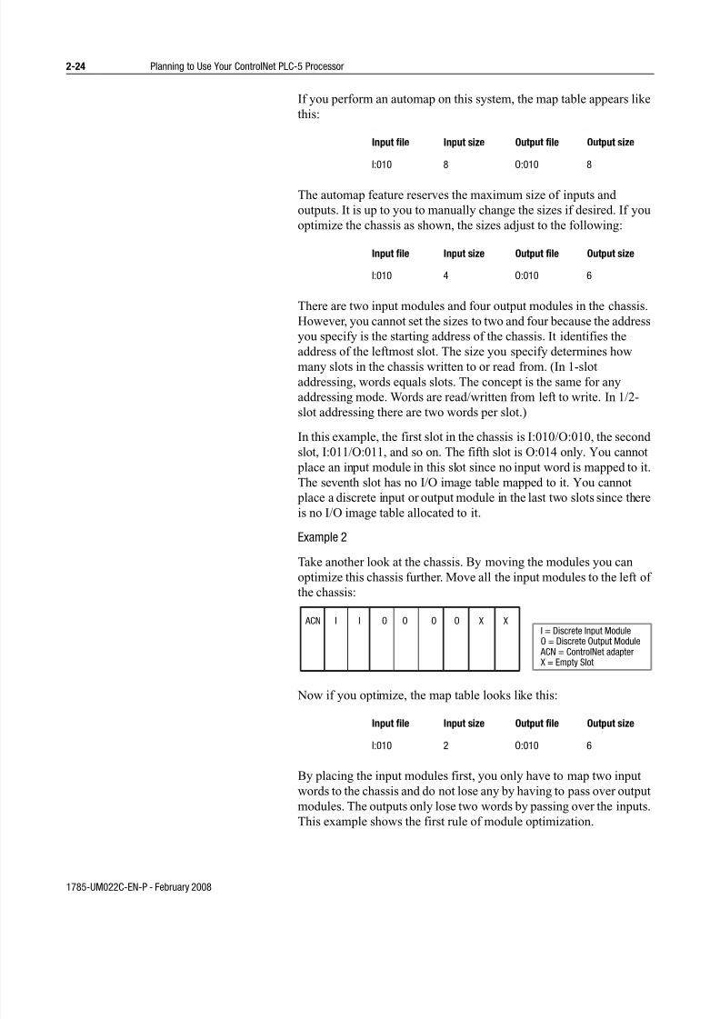
7/27/2019 ControlNet PLC-5 Programmable Controllers User Manual
http://slidepdf.com/reader/full/controlnet-plc-5-programmable-controllers-user-manual 62/148
1785-UM022C-EN-P - February 2008
2-24 Planning to Use Your ControlNet PLC-5 Processor
If you perform an automap on this system, the map table appears like
this:
The automap feature reserves the maximum size of inputs and
outputs. It is up to you to manually change the sizes if desired. If you
optimize the chassis as shown, the sizes adjust to the following:
There are two input modules and four output modules in the chassis.
However, you cannot set the sizes to two and four because the address
you specify is the starting address of the chassis. It identifies the
address of the leftmost slot. The size you specify determines howmany slots in the chassis written to or read from. (In 1-slot
addressing, words equals slots. The concept is the same for any
addressing mode. Words are read/written from left to write. In 1/2-
slot addressing there are two words per slot.)
In this example, the first slot in the chassis is I:010/O:010, the second
slot, I:011/O:011, and so on. The fifth slot is O:014 only. You cannot
place an input module in this slot since no input word is mapped to it.
The seventh slot has no I/O image table mapped to it. You cannot
place a discrete input or output module in the last two slots since there
is no I/O image table allocated to it.
Example 2
Take another look at the chassis. By moving the modules you can
optimize this chassis further. Move all the input modules to the left of
the chassis:
Now if you optimize, the map table looks like this:
By placing the input modules first, you only have to map two input
words to the chassis and do not lose any by having to pass over output
modules. The outputs only lose two words by passing over the inputs.
This example shows the first rule of module optimization.
Input file Input size Output file Output size
I:010 8 O:010 8
Input file Input size Output file Output size
I:010 4 O:010 6
Input file Input size Output file Output size
I:010 2 O:010 6
ACN I I O O O OI = Discrete Input ModuleO = Discrete Output Module
ACN = ControlNet adapterX = Empty Slot
X X

7/27/2019 ControlNet PLC-5 Programmable Controllers User Manual
http://slidepdf.com/reader/full/controlnet-plc-5-programmable-controllers-user-manual 63/148
1785-UM022C-EN-P - February 2008
Planning to Use Your ControlNet PLC-5 Processor 2-25
First Rule of
Module Optimization
When placing discrete modules, put the type (input or output) you
have the least of to the left in the chassis.
Example 3
Some chassis may contain analog modules, communication cards, or
power supplies. Examine the following chassis:
This chassis contains an analog module and a power supply. Assume
all analog modules on a ControlNet network are mapped to an integer
table in the PLC-5 processor. Power supplies do not require any I/O
image table. Therefore, the optimal configuration of this chassis is:
Since analog modules and power supplies do not need any I/O image
space you should place them to the right so that you don’t have to
waste any inputs or outputs passing over these modules. This leads to
the second important module placement rule of optimization.
Input file Input size Output file Output size
I:010 6 O:010 2
ACN A I O I O PS I = Discrete Input ModuleO = Discrete Output Module
ACN = ControlNet adapter A = Analog ModulePS = Power Supply
I I
ACN O O I I I I I = Discrete Input ModuleO = Discrete Output Module ACN = ControlNet adapter A = Analog ModulePS = Power Supply
A PS

7/27/2019 ControlNet PLC-5 Programmable Controllers User Manual
http://slidepdf.com/reader/full/controlnet-plc-5-programmable-controllers-user-manual 64/148
1785-UM022C-EN-P - February 2008
2-26 Planning to Use Your ControlNet PLC-5 Processor
Second Rule of
Module Optimization
Place modules that do not require I/O image table space to the right
in the chassis.
Example 4
To understand how optimization with a ControlNet network preserves
I/O image space, look at the following example system:
The following chart shows how a Remote I/O system compares to
one optimized with a ControlNet network.
If you install the system on a PLC-5/20C processor, the Remote I/O
network option would be out of I/O image space, while the
ControlNet network option would have used only one-third of the
available I/O image space. You must take into account futureexpansion when optimizing the I/O.
I = Discrete Input ModuleO = Discrete Output Module
ACN = ControlNet adapter A = Analog ModulePS = Power Supply
Chassis 1
Chassis 2
Chassis 3
ACN A A A A A a A PS A A
ACN I O O O O O O PS
ACN O I I I I I I PS
Remote I/O ControlNet Network
Input Output Input Output
Chassis Address Size Address Size Address Size Address Size
1
2
3
I:010
I:020
I:030
8
8
8
O:010
O:010
O:030
8
8
8
I:010
I:011
n/a
1
7
0
O:010
O:017
n/a
7
1
0
Total Used 24 (3 racks) 24 (3 racks) 8 (1 rack) 8
Remaining 0 0 16 (2 racks) 16

7/27/2019 ControlNet PLC-5 Programmable Controllers User Manual
http://slidepdf.com/reader/full/controlnet-plc-5-programmable-controllers-user-manual 65/148
1785-UM022C-EN-P - February 2008
Planning to Use Your ControlNet PLC-5 Processor 2-27
Example 4
Examine the following system:
Assume you want to add an additional output module in one of the
empty slots in the second chassis. Only three words of output are
mapped to the second chassis. You have to change the output size inthe second chassis to five to get to the first empty slot. However, this
example started mapping the third chassis at O:023. If you try to set
the second chassis size to five, you get an overlap error because
words O:023 and O:024 are being used in the third chassis. You can
always change the starting address of the third chassis, but then you
must change any references to the outputs in your program. It may be
better to start mapping the third chassis at O:027 to allow for output
expansion. You can add input modules in the empty slots without
changing anything since there are already eight words of inputs
mapped to the chassis.
Optimizing the I/O Image Table with Slot Complementary
Slot complementary makes use of the ability of a chassis to share
inputs or outputs between adjacent slots. This allows you to set the
density of the chassis to a lower value than the modules used in the
chassis and then share the I/O between the slots. For example, you
can set a chassis to 2-slot addressing and then place 16-point modules
in the chassis, alternating input and output modules.
I O O I I O I = Discrete Input ModuleO = Discrete Output Module
ACN = ControlNet adapter A = Analog ModulePS = Power SupplyX = Empty Slot
O O
I A O A X X A I
Chassis 1
Chassis 2
Chassis 3
O O O I I I I A
ACN
ACN
ACN
Input file Input size Output file Output size
Chassis 1 I:010 5 O:010 8
Chassis 2 I:015 8 O:020 3
Chassis 3 I:025 7 O:023 3

7/27/2019 ControlNet PLC-5 Programmable Controllers User Manual
http://slidepdf.com/reader/full/controlnet-plc-5-programmable-controllers-user-manual 66/148
1785-UM022C-EN-P - February 2008
2-28 Planning to Use Your ControlNet PLC-5 Processor
Example 1
Examine the following chassis:
In this example the first input module uses eight inputs from the first
slot and eight inputs from the second slot (not used by the output
module in the second slot). The first output module uses eight outputs
from the first slot and eight outputs from the second slot, and so on.
Given an 8-slot chassis in 2-slot addressing, there are four words of
inputs and four words of outputs used in this chassis. On a ControlNet
network, you can map four words of inputs and four words of outputs
to this chassis and no I/O image space is wasted. If you set the
addressing mode to 1-slot addressing and use the methods described in the previous section you waste either four words of input or four
words of output image table.
This method works extremely well for cases where there are equal
numbers of input and output cards. However, in most cases there are
not the same number of each module.
Example 2
Examine the following chassis:
In this case you can map two words of input and four words of output
to the chassis and not waste any I/O image table. However, you waste
physical space (note the two empty slots).
Look at the case where you have 14 input modules and two output
modules. If you use slot complementary, you have to purchase an
additional chassis, and therefore an additional adapter and power
supply, since you can only put eight of the input modules in one
chassis (one module every other slot). If you do not use slot
complementary, you can fit all the cards in one chassis and only
sacrifice two output image table words.
With the slot-complementary method you cannot just put any module
anywhere. If you wish to add an output module to the chassis shown
above you cannot since there are no output slots available; you have
to start a new chassis.
I O I O I O I = Discrete Input ModuleO = Discrete Output Module
ACN = ControlNet adapter
I O ACN
2-slot addressing16-point modules
I O I O X O I = Discrete Input ModuleO = Discrete Output Module
ACN = ControlNet adapterX = Empty Slot
X O ACN
2-slot addressing16-point modules

7/27/2019 ControlNet PLC-5 Programmable Controllers User Manual
http://slidepdf.com/reader/full/controlnet-plc-5-programmable-controllers-user-manual 67/148
1785-UM022C-EN-P - February 2008
Planning to Use Your ControlNet PLC-5 Processor 2-29
Summary
There are two methods to optimize the use of I/O image table in a
ControlNet PLC-5 processor. There are tradeoffs in using each
method which are summarized in the following table.
The best solution in most cases is to combine the two methods.
Examine the module requirements at any given chassis or location
and see which method fits best. You may find in some areas you have
an equal number of input and output modules, and slot
complementary optimizing works well. However, you may find in
other areas there are space limitations which require the use of the
smallest possible chassis, and therefore, you cannot waste slots using
slot complementary.
A final point to be aware of is that each system is unique and you
must apply these techniques accordingly. For example, you may havethe following chassis:
Using strict rules of optimization you might immediately arrange the
chassis like this:
Method: Tradeoffs:
optimize without slotcomplementary
• allows optimization of I/O image table, butnot to the extent if using slot complementary
• does not waste chassis slots
• can put any module anywhere (provided I/Otable exists for that slot)
optimize with slot complementary • allows complete optimization of the I/Oimage table
• can waste chassis slots and requireadditional chassis
• can only put modules in odd or even slots,depending on the module type
I I O I I I I = Discrete Input ModuleO = Discrete Output Module
ACN = ControlNet adapter
O I ACN
2-slot addressing16-point modules
O O I I I II = Discrete Input ModuleO = Discrete Output Module
ACN = ControlNet adapter
I I ACN2-slot addressing16-point modules

7/27/2019 ControlNet PLC-5 Programmable Controllers User Manual
http://slidepdf.com/reader/full/controlnet-plc-5-programmable-controllers-user-manual 68/148
1785-UM022C-EN-P - February 2008
2-30 Planning to Use Your ControlNet PLC-5 Processor
However, the overall system may be heavy on inputs, and there are no
concerns about the output image table. In this case you may want to
conserve the input image table for this chassis and arrange it as
follows:
When deciding when, where, and what type of optimization to use,
you have to balance:
• space limitations
• additional costs (extra chassis, adapters, etc.)
• I/O image table availability
• future expansion
I I I I I I I = Discrete Input ModuleO = Discrete Output Module
ACN = ControlNet adapter
O O ACN
2-slot addressing16-point modules
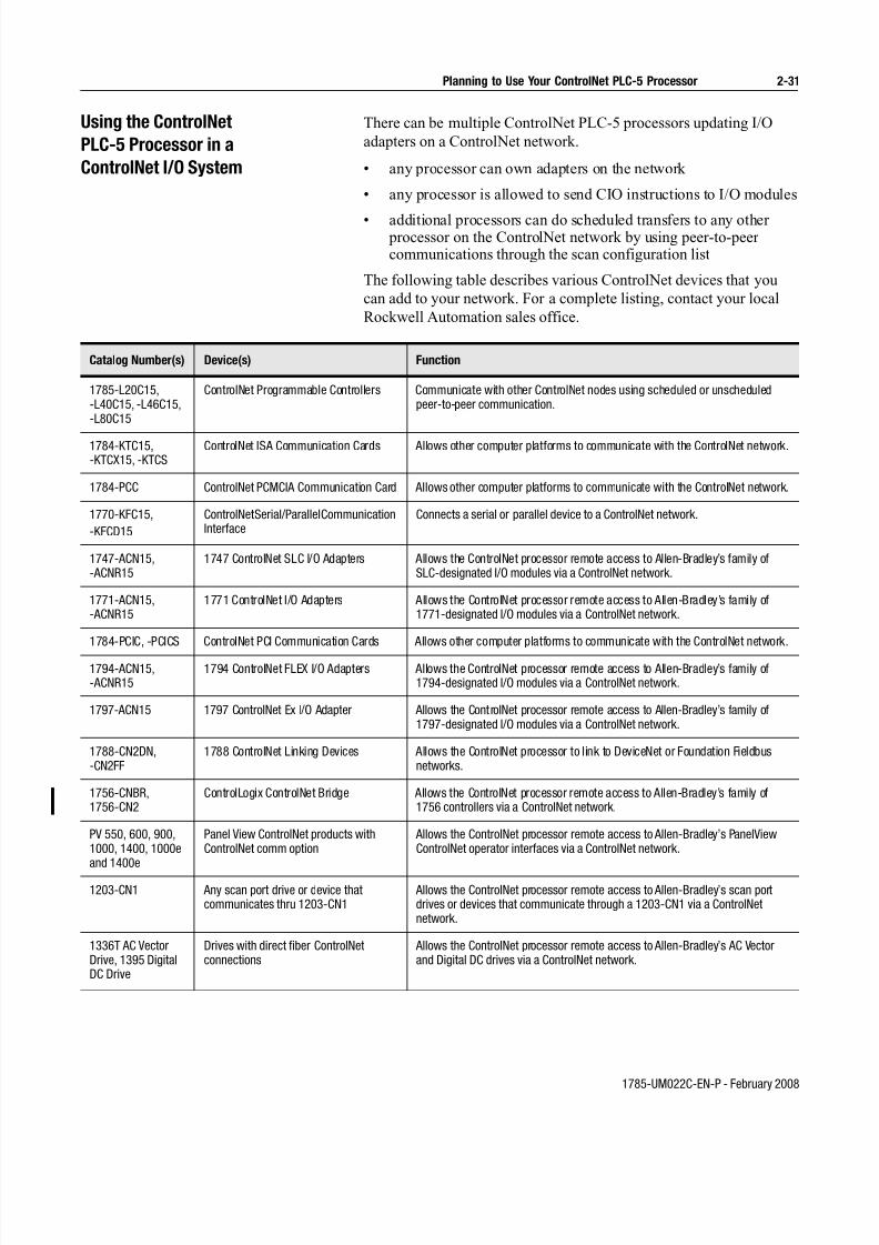
7/27/2019 ControlNet PLC-5 Programmable Controllers User Manual
http://slidepdf.com/reader/full/controlnet-plc-5-programmable-controllers-user-manual 69/148
1785-UM022C-EN-P - February 2008
Planning to Use Your ControlNet PLC-5 Processor 2-31
Using the ControlNet
PLC-5 Processor in a
ControlNet I/O System
There can be multiple ControlNet PLC-5 processors updating I/O
adapters on a ControlNet network.
• any processor can own adapters on the network
• any processor is allowed to send CIO instructions to I/O modules
• additional processors can do scheduled transfers to any other processor on the ControlNet network by using peer-to-peer communications through the scan configuration list
The following table describes various ControlNet devices that you
can add to your network. For a complete listing, contact your local
Rockwell Automation sales office.
Catalog Number(s) Device(s) Function
1785-L20C15,-L40C15, -L46C15,-L80C15
ControlNet Programmable Controllers Communicate with other ControlNet nodes using scheduled or unscheduledpeer-to-peer communication.
1784-KTC15,-KTCX15, -KTCS
ControlNet ISA Communication Cards Allows other computer platforms to communicate with the ControlNet network.
1784-PCC ControlNet PCMCIA Communication Card Allows other computer platforms to communicate with the ControlNet network.
1770-KFC15,
-KFCD15
ControlNet Serial/Parallel CommunicationInterface
Connects a serial or parallel device to a ControlNet network.
1747-ACN15,-ACNR15
1747 ControlNet SLC I/O Adapters Allows the ControlNet processor remote access to Allen-Bradley’s family ofSLC-designated I/O modules via a ControlNet network.
1771-ACN15,-ACNR15
1771 ControlNet I/O Adapters Allows the ControlNet processor remote access to Allen-Bradley’s family of1771-designated I/O modules via a ControlNet network.
1784-PCIC, -PCICS ControlNet PCI Communication Cards Allows other computer platforms to communicate with the ControlNet network.
1794-ACN15,-ACNR15
1794 ControlNet FLEX I/O Adapters Allows the ControlNet processor remote access to Allen-Bradley’s family of1794-designated I/O modules via a ControlNet network.
1797-ACN15 1797 ControlNet Ex I/O Adapter Allows the ControlNet processor remote access to Allen-Bradley’s family of1797-designated I/O modules via a ControlNet network.
1788-CN2DN,-CN2FF
1788 ControlNet Linking Devices Allows the ControlNet processor to link to DeviceNet or Foundation Fieldbusnetworks.
1756-CNBR,1756-CN2
ControlLogix ControlNet Bridge Allows the ControlNet processor remote access to Allen-Bradley’s family of1756 controllers via a ControlNet network.
PV 550, 600, 900,1000, 1400, 1000eand 1400e
Panel View ControlNet products withControlNet comm option
Allows the ControlNet processor remote access to Allen-Bradley’s PanelViewControlNet operator interfaces via a ControlNet network.
1203-CN1 Any scan port drive or device thatcommunicates thru 1203-CN1
Allows the ControlNet processor remote access to Allen-Bradley’s scan portdrives or devices that communicate through a 1203-CN1 via a ControlNetnetwork.
1336T AC VectorDrive, 1395 DigitalDC Drive
Drives with direct fiber ControlNetconnections
Allows the ControlNet processor remote access to Allen-Bradley’s AC Vectorand Digital DC drives via a ControlNet network.

7/27/2019 ControlNet PLC-5 Programmable Controllers User Manual
http://slidepdf.com/reader/full/controlnet-plc-5-programmable-controllers-user-manual 70/148
1785-UM022C-EN-P - February 2008
2-32 Planning to Use Your ControlNet PLC-5 Processor
Personal computer
with 1784-KTCX15 card
(ISA-based) and
your HMI orprogramming software
Personal computer or
other serial device
and your HMI orprogramming software
Laptop computer with
1784-PCC card (PCMCIA-based)
and your HMI orprogramming software
Serial connection
1770-KFC15
Interface
PLC-5/40C
ControlNet Network
1794-ACNR15
Flex I/O Adapter
1771-ACNR15
Adapter
Data Highway Plus link
Remote I/O link
PLC-5/40C 1784-PCC1 to PLC-5 (NAP
port or any other NAP port)*
Example of a ControlNet Network without Redundant Media
Personal computer
with PCIC card (PCI-based)
and your HMIor programming software
Tap (4 choices)
1786-TPR
Tap (4 choices)
1786-TPR
Tap (4 choices)
1786-TPR
1747-ACNR15
Adapter
Personal computer or
other serial device
and your HMI or
programming software
Serial connection
1770-KFC15
Interface
ControlNet Network
1794-ACNR15
Flex I/O Adapter
1771-ACNR15
Adapter
Data Highway Plus link
Remote I/O link
PLC-5/40C
Example of a ControlNet Network with Redundant Media
Personal computer
with 1784-KTCX15 card
(ISA-based) andyour HMI or
programming software
Laptop computer with
1784-PCC card (PCMCIA-based)
and your HMI or
programming software
PLC-5/40C
Personal computer
with PCIC card (PCI-based)and your HMI
or programming software
Tap (4 choices)
1786-TPR
1747-ACNR15
Adapter
Tap (4 choices)
1786-TPR
Tap (4 choices)
1786-TPR
1784-PCC1 to PLC-5 (NAP
port or any other NAP port)*

7/27/2019 ControlNet PLC-5 Programmable Controllers User Manual
http://slidepdf.com/reader/full/controlnet-plc-5-programmable-controllers-user-manual 71/148
1785-UM022C-EN-P - February 2008
Planning to Use Your ControlNet PLC-5 Processor 2-33
Distributed Keeper Functionality
All ControlNet processors now keep the ControlNet configuration.
The processor with the lowest node address acts as the master keeper,
while the other processors serve as backups. If the master keeper
drops off the network, the next-lowest numbered processor takes over
as the master keeper. No user intervention is required.
Important: ControlNet PLC-5 programmable controllers with
firmware revision E/B, D/C, or C/L are single keeper devices.
All later releases are distributed keeper devices.
There are two rules you must follow when combining single keeper
devices and distributed keeper devices on the same network:
• if there is a single keeper device at node 1, there can be nodistributed keeper devices on the network
• if there are distributed keeper devices on the network, singlekeeper devices can also be allowed on the network. However,
there cannot be a single keeper device at node 1.
If you plan to have distributed keeper devices on the network, we
recommend that you flash upgrade the single keeper devices to be
distributed keeper devices.
When used in a Class I, Division 2, hazardous
location, this equipment must be mounted in a
suitable enclosure with proper wiring method that
complies with the governing electrical codes.
WARNING
!

7/27/2019 ControlNet PLC-5 Programmable Controllers User Manual
http://slidepdf.com/reader/full/controlnet-plc-5-programmable-controllers-user-manual 72/148
1785-UM022C-EN-P - February 2008
2-34 Planning to Use Your ControlNet PLC-5 Processor
Converting from a Non-ControlNet
Remote I/O System to a ControlNet
I/O System
When you download archived files to a ControlNet PLC-5 processor,
the programming software ignores Channel 2 configuration
information from anything other than a ControlNet-processor
program because Channel 2 is reserved for ControlNet
communication on the ControlNet processors. The software sets
Channel 2 to the default ControlNet configuration.
Program files1
for this process:
Archived from a:
On channel:
Can be run on a
ControlNet
PLC-5 channel:
If they fit and are:
Messaging and I/O • PLC-5/11
• PLC-5/20
• PLC-5/20C15
• PLC-5/20E
• PLC-5/30• PLC-5/40
• PLC-5/40C15
• PLC-5/46C15
• PLC-5/40E
• PLC-5/40L
• PLC-5/60
• PLC-5/60L
• PLC-5/80
• PLC-5/80C15• PLC-5/80E
0 0 downloaded unchanged
1A 1A
• PLC-5/20
• PLC-5/20C15
• PLC-5/20E
• PLC-5/30
• PLC-5/40
• PLC-5/40C15
• PLC-5/46C15
• PLC-5/40E
• PLC-5/40L
• PLC-5/60
• PLC-5/60L
• PLC-5/80
• PLC-5/80C15
• PLC-5/80E
1B 1B
• PLC-5/20C15
• PLC-5/40C15
• PLC-5/46C15
• PLC-5/80C15
2 2

7/27/2019 ControlNet PLC-5 Programmable Controllers User Manual
http://slidepdf.com/reader/full/controlnet-plc-5-programmable-controllers-user-manual 73/148
1785-UM022C-EN-P - February 2008
Planning to Use Your ControlNet PLC-5 Processor 2-35
Converting from ControlNet Phase
1.0 or 1.25 to ControlNet Phase 1.5
ControlNet phase 1.0 or 1.25 products will not work in a ControlNet
1.5 system.
To convert ControlNet phase 1.0 or 1.25 to ControlNet phase 1.5,contact your local Rockwell Automation sales office or distributor.
Messaging and I/O continued
• PLC-5/11
• PLC-5/20
• PLC-5/20C15
• PLC-5/20E
• PLC-5/30
• PLC-5/40
• PLC-5/40C15
• PLC-5/40E
• PLC-5/40L
• PLC-5/46C15
• PLC-5/60
• PLC-5/60L
• PLC-5/80
• PLC-5/80C15
• PLC-5/80E
1A 2 performed by the ControlNet network—youmust make these changes manually by
reprogramming2,3,4
• PLC-5/20
• PLC-5/20C15
• PLC-5/20E
• PLC-5/30
• PLC-5/40
• PLC-5/40C15
• PLC-5/40E
• PLC-5/40L
• PLC-5/46C15
• PLC-5/60
• PLC-5/60L
• PLC-5/80
• PLC-5/80C15
• PLC-5/80E
1B 2
• PLC-5/40
• PLC-5/60
• PLC-5/80 2A or 2B 2
1A or 1B performed by DH+ or remote I/O—you mustmake these changes manually by
reprogramming5
• PLC-5/20E
• PLC-5/40E
• PLC5/40L
• PLC-5/60L
• PLC-5/80E
2 1A or 1B performed by DH+ or remote I/O—you mustmake these changes manually by
reprogramming5
2 performed by the ControlNet network—youmust make these changes manually by
reprogramming3,4,5
1 These include processor files, data-table files, and port configurations.2 If you do not update the program, the ControlNet processor will fault.3 You must change block-transfer instructions for the ControlNet system from the standard block transfer read (BTR) and block transfer write (BTW) instructions to
scheduled transfers or to unscheduled CIO instructions.4 You must edit non-ControlNet PLC-5 programs containing references to the I/O Status File for use with I/O connected via the ControlNet network. Information
regarding ControlNet status is stored in a separate data file that you specify through the programming software.5 If you do not update the program, the data-table locations corresponding to the “missing” I/O devices will not be updated.
Program files1
for this process:
Archived from a:
On channel:
Can be run on a
ControlNet
PLC-5 channel:
If they fit and are:

7/27/2019 ControlNet PLC-5 Programmable Controllers User Manual
http://slidepdf.com/reader/full/controlnet-plc-5-programmable-controllers-user-manual 74/148
1785-UM022C-EN-P - February 2008
2-36 Planning to Use Your ControlNet PLC-5 Processor
Notes
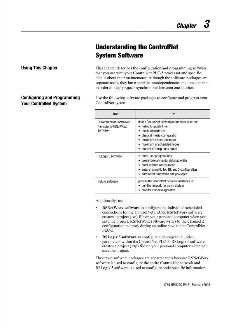
7/27/2019 ControlNet PLC-5 Programmable Controllers User Manual
http://slidepdf.com/reader/full/controlnet-plc-5-programmable-controllers-user-manual 75/148
1785-UM022C-EN-P - February 2008
Chapter 3
Understanding the ControlNet
System SoftwareUsing This Chapter This chapter describes the configuration and programming software
that you use with your ControlNet PLC-5 processor and specific
details about their maintenance. Although the software packages are
separate tools, they have specific interdependencies that must be met
in order to keep projects synchronized between one another.
Configuring and Programming
Your ControlNet System
Use the following software packages to configure and program your
ControlNet system.
Additionally, use:
• RSNetWorx software to configure the individual scheduled connections for the ControlNet PLC-5. RSNetWorx softwarecreates a project (.xc) file on your personal computer when yousave the project. RSNetWorx software writes to the Channel 2configuration memory during an online save to the ControlNet
PLC-5.
• RSLogix 5 software to configure and program all other parameters within the ControlNet PLC-5. RSLogix 5 softwarecreates a project (.rsp) file on your personal computer when yousave the project.
These two software packages are separate tools because RSNetWorx
software is used to configure the entire ControlNet network and
RSLogix 5 software is used to configure node-specific information.
Use: To:
RSNetWorx for ControlNet
(henceforth RSNetWorx)software
define ControlNet network parameters, such as:
• network update time
• media redundancy
• physical media configuration
• maximum scheduled nodes
• maximum unscheduled nodes
• monitor I/O map entry status
RSLogix 5 software • enter user program files
• create/delete/monitor data table files
• enter module configuration
• enter channel 0, 1A, 1B, and 3 configuration
• administer passwords and privileges
RSLinx software provide the ControlNet network interfaces to:
• poll the network for active devices
• monitor station diagnostics

7/27/2019 ControlNet PLC-5 Programmable Controllers User Manual
http://slidepdf.com/reader/full/controlnet-plc-5-programmable-controllers-user-manual 76/148
1785-UM022CEN-P - February 2008
3-2 Understanding the ControlNet System Software
Also, the ControlNet network requires that the entire network be
configured at one time to make sure all scheduled connections are
performed at their configured packet rates.
Two interdependencies exist between RSNetWorx and RSLogix 5
software:
• the I/O configuration utility invoked in RSLogix 5 software
• the ControlNet configuration information is created and saved inRSNetWorx software, but is also saved and downloaded inRSLogix 5 software
I/O Configuration Utility
The I/O configuration utility in RSLogix 5 software is used to
simplify the configuration of intelligent I/O modules. It is important
to understand the difference between I/O configuration over remote
I/O vs. I/O configuration over ControlNet:
• over remote I/O, the information displayed and entered in theconfiguration applet is always read and written to the data table.Thus, all of the I/O configuration functionality over remote I/O iscontained with the RSLogix 5 application.
• over ControlNet, the information displayed and entered in theconfiguration applet is read and written to both the data table and the RSNetWorx project (.xc) file.
The I/O configuration data must be read and written to the
RSNetWorx project (.xc) file so that the user can download the
I/O configuration data from RSNetWorx software. If the
RSNetWorx project (.xc) file was not updated with the I/O
configuration edits done within the I/O configuration utility, theedits would be lost when that RSNetWorx project file was
downloaded.
You must configure the association to the RSNetWorx project (.xc)
file in RSLogix 5 software so that RSLogix 5 software knows which
RSNetWorx project (.xc) file to access the I/O configuration
information. You can do this within the Controller Properties window
in RSLogix 5 software. If you don’t use the I/O configuration utility
to edit or monitor ControlNet scheduled connections, the association
to the RSNetWorx project (.xc) file in RSLogix 5 software is
unnecessary.
Certain circumstances can cause the data table configuration
information to differ from what is stored in the RSNetWorx project
(.xc) file. This can occur when program logic is used to modify the
contents of the data table for purposes of reconfiguring a module via a
path other than the I/O configuration utility. If such “on the fly”
reconfiguration is necessary for your application, consider that
subsequently launching the I/O configuration utility applet will result
in outdated information being displayed, unless that information has
been imported into the RSNetWorx project (.xc) file.

7/27/2019 ControlNet PLC-5 Programmable Controllers User Manual
http://slidepdf.com/reader/full/controlnet-plc-5-programmable-controllers-user-manual 77/148
1785-UM022C-EN-P - February 2008
Understanding the ControlNet System Software 3-3
Under these circumstances, consider the following guidelines:
• when configuring intelligent modules over ControlNet, anyconfiguration changes should be performed via a module’srespective applet in the I/O configuration utility. This will ensurethat the edits are written to both the data table and the
RSNetWorx project (.xc) file.
• if you must configure an intelligent module over ControlNet via program logic, you must then upload the online network configuration in RSNetWorx software to synchronize the contentsof the data table with the RSNetWorx project (.xc) file. This willensure that the I/O configuration utility applet will containcurrent information the next time it is launched.
Uploading and Downloading Software Projects
Considering that both RSLogix 5 and RSNetWorx software can
upload and download the ControlNet configuration information, you
must make sure that both the RSLogix 5 project (.rsp) file and theRSNetWorx project (.xc) file contain the same ControlNet
configuration information. For example, if outdated ControlNet
configuration information is present in the RSLogix 5 project (.rsp)
file, a download of the RSLogix 5 project may download ControNet
configuration information that does not match the current ControlNet
network.
There are two reasons why the RSLogix 5 project (.xc) file contains
ControlNet configuration information:
• the RSNetWorx tool can only download to the entire ControlNetnetwork. For example, in an application where a single
ControlNet PLC-5 needs to have its program downloaded,RSNetWorx software will attempt to download all nodes on theControlNet network. This will be time-consuming and requirethat all ControlNet PLC-5 processors on the ControlNet network be placed in PROGRAM mode.
• the RSLogix 5 software download can download everything to aControlNet PLC-5 in a single download. If the ControlNetconfiguration information was not contained within the RSLogix5 project, both an RSLogix 5 project download and anRSNetWorx project download would be required.
Verify that ControlNet PLC-5 Configuration Matches Network
Information
To make sure that the ControlNet configuration information
downloaded to the ControlNet PLC-5 processor matches the current
ControlNet network information, follow one of these procedures:

7/27/2019 ControlNet PLC-5 Programmable Controllers User Manual
http://slidepdf.com/reader/full/controlnet-plc-5-programmable-controllers-user-manual 78/148
1785-UM022CEN-P - February 2008
3-4 Understanding the ControlNet System Software
Download from both RSNetWorx and RSLogix 5 software
You can download the ControlNet configuration information from
RSNetWorx software and the remaining controller information from
RSLogix 5 software. When downloading the project from RSLogix 5
software, a dialog box appears and asks whether the ControlNet
configuration information stored in the RSLogix 5 project should be
downloaded.
With this approach, you will want to keep the existing ControlNet
configuration that is currently on the ControlNet PLC-5 processor.
Download from RSLogix 5 Software Only
You can download the entire program from RSLogix 5 software while
keeping the ControlNet configuration information up to date. When
downloading the ControlNet configuration information from
RSLogix 5 software, a dialog box appears and asks whether the
ControlNet configuration information stored in the RSLogix 5 projectshould be downloaded.
With this approach, you will want to overwrite the existing
ControlNet configuration that is currently on the ControlNet PLC-5
processor with the ControlNet configuration information that is
stored in the RSLogix 5 project (.rsp) file.
The ControlNet configuration information in RSLogix 5 software is
kept up to date by uploading from the ControlNet PLC-5 processor
and by saving a new RSLogix 5 project (.rsp) file following every
save performed in RSNetWorx software, or following an RSNetWorx
project download if a save was performed off-line.
Important: This approach simplifies the download to a single
operation, however it requires the maintenance of keeping the
RSLogix 5 project (.rsp) file up to date with the current ControlNet
network configuration information for every PLC-5 processor on the
ControlNet network. To do this, you must perform the RSLogix 5
upload and save for each and every save performed in RSNetWorx
software, even if no ControlNet configuration information changed
for any ControlNet PLC-5 processor. This is required because a
network keeper signature is reevaluated every save and is unique for
every save. The network keeper signature is downloaded to every
keeper-capable device on the ControlNet network.
Using RSNetWorx Software to Perform Verification Activities
After a Download or Save in RSNetWorx Software
We recommend that you perform two verification activities following
a download or save operation in RSNetWorx software:
• Verify Keeper Signatures
• Verify Scanner Signatures

7/27/2019 ControlNet PLC-5 Programmable Controllers User Manual
http://slidepdf.com/reader/full/controlnet-plc-5-programmable-controllers-user-manual 79/148
1785-UM022C-EN-P - February 2008
Understanding the ControlNet System Software 3-5
To verify keeper signatures:
1. In Network menu, choose Keeper Status
2. If any keepers are invalid, select the node(s) and click Update
Keeper
To verify scanner signatures:
1. In Network menu, choose Scanner Signature Status
2. If any scanners are invalid, download the RSNetWorx project to
the processors that indicate a scanner signature mismatch (you
may have to follow additional troubleshooting procedures in
RSNetWorx software to correct the scanner signature mismatch).
Merge-Save Functionality
When you add or delete nodes or when you add, modify, or delete I/O
map table entries, only those processors on the network whose
ControlNet schedules need to change are required to be in Programmode. This feature requires RSNetWorx for ControlNet software
version 1.6 or later.
During the save operation, RSNetWorx software gives you two
options:
• Optimize schedule for all connections: RSNetWorx software
recalculates the ControlNet schedule for all the nodes on the
ControlNet network. The new schedule is downloaded to all the
processors. The processors close all of their existing connections
and then reopen their connections according to the new schedule.
This option requires that all the processors be in Program mode.
• Merge changes into existing schedule: RSNetWorx software
merges the pending changes into the current ControlNet schedule.
The new schedule is only downloaded to those processors that are
affected by the change. Only those processors that are affected by
the change have to be in Program mode. All other processors on
the network can remain in Run mode and their connections
remain open. This option is only available if the current schedule
can accommodate the pending changes and if the ControlNet
network parameters (such as NUT, maximum scheduled address,
maximum unscheduled address, or media redundancy) do not
change.
Important: Performing a download via RSNetWorx software may
require all the processors to be in Program mode.
For More Information For more information about using these software packages, see the
online help systems included with RSNetWorx for ControlNet and
RSLogix 5 software.
7/27/2019 ControlNet PLC-5 Programmable Controllers User Manual
http://slidepdf.com/reader/full/controlnet-plc-5-programmable-controllers-user-manual 80/148
1785-UM022CEN-P - February 2008
3-6 Understanding the ControlNet System Software
Notes

7/27/2019 ControlNet PLC-5 Programmable Controllers User Manual
http://slidepdf.com/reader/full/controlnet-plc-5-programmable-controllers-user-manual 81/148
1785-UM022C-EN-P - February 2008
Chapter 4
Programming Your
ControlNet SystemUsing This Chapter
Using ControlNet
Message Instructions
You can use the Message (MSG) instruction and the MG data type to
send message commands over the ControlNet system within the local
ControlNet link:
• PLC-5 TYPED WRITE
• PLC-5 TYPED READ
• PLC-3 WORD RANGE READ
• PLC-3 WORD RANGE WRITE
• PLC-2 UNPROTECTED READ
• PLC-2 UNPROTECTED WRITE
Use your programming software to go to the instruction entry for
message block screen.
Topic Page
ControlNet message instructions 4-1
ControlNet I/O transfer instructions 4-3
ControlNet immediate data input and output instructions 4-6
Using Selectable Timed Interrupts (STIs) in a program on aControlNet network
4-9
Recovering from Major Fault Codes 200 and 201 4-9
If you want to: Do this:
change the commandtype
Select one of the following:
• PLC-5 TYPED WRITE—to select a write operationto another PLC-5 processor
• PLC-5 TYPED READ—to select a read operationfrom another PLC-5 processor
• PLC-3 WORD RANGE READ—to select a writeoperation to another PLC-3 processor
• PLC-3 WORD RANGE WRITE—to select a readoperation from another PLC-3 processor
• PLC-2 UNPROTECTED READ—to select a writeoperation to another PLC-2 processor
• PLC-2 UNPROTECTED WRITE—to select a readoperation from another PLC-2 processor
enter a PLC-5 datatable address
Type the PLC-5 data table address.

7/27/2019 ControlNet PLC-5 Programmable Controllers User Manual
http://slidepdf.com/reader/full/controlnet-plc-5-programmable-controllers-user-manual 82/148
1785-UM022C-EN-P - February 2008
4-2
The fields of the MG data type that you can directly address are:
For more detailed information about writing ladder programs and
using message instructions, see your programming software
documentation.
Multihop Messaging Via the MSG Instruction
You can use the MSG instruction to communicate from a processor
on one ControlNet link to a processor on another ControlNet link via
ControlBus using 1756-CNB ControlNet bridge modules.
You can also configure a ControlNet ladder MSG instruction to:
• a Data Highway Plus device by bridging across the 1756-CNB(R)and 1756-DHRIO modules
• an Ethernet device by bridging across the 1756-CNB(R) and 1756-ENET modules
Refer to your programming software documentation for information
about configuring multihop messages.
enter the size inelements
Type a number of elements from 1 to 1000.
enter the destination
network address
Type a number from 1 to 99.
enter a destinationdata table address
Type the destination data table address.
If you want to: Do this:
Field Definition Location
.EW Enabled-waiting flag bit word 0, bit 02
.CO Continuous control bit word 0, bit 03
.ER Errored flag bit word 0, bit 04
.DN Done flag bit word 0, bit 05
.ST Started flag bit word 0, bit 06
.EN Enabled flag bit word 0, bit 07
.TO Abort (Time out) control bit word 0, bit 08
.NR No-response flag bit—not used word 0, bit 09
.NC No-cache bit word 0, bit 10
.ERR Error-code word word 1
.RLEN Requested length word word 2
.DLEN Done length word word 3
.DATA[0] through.DATA[51] Remaining words words 4 through 55
1756-CNB
ControlBus
ControlNet Link 1 ControlNet Link 2

7/27/2019 ControlNet PLC-5 Programmable Controllers User Manual
http://slidepdf.com/reader/full/controlnet-plc-5-programmable-controllers-user-manual 83/148
1785-UM022C-EN-P - February 2008
4-3
Option to Close Communication Connection when MSG is Done
This feature allows you to configure the ControlNet ladder MSG
instruction to close its communication connection when the message
operation is done - thus conserving ControlNet resources on low duty
rate messages. Do this by setting the NC configuration bit in the
ladder MSG control file.
Understanding the ControlNet PLC-2 Compatibility File
When a PLC-2 command is received from the ControlNet network,
the ControlNet PLC-5 processor uses the user-specified file as the
PLC-2 compatibility file. All PLC-2 commands received from the
ControlNet network use the same PLC-2 compatibility file. The
ControlNet PLC-5 processor uses the value stored in S:73 of the
processor status file as the PLC-2 compatibility file number.
The PLC-2 file number must be between 3 and 999, inclusive. The
corresponding data table file must exist and be large enough toaccommodate the PLC-2 requests. You can use a MOV instruction in
the ladder program to update S:73.
The PLC-2 type MSG instructions error if the PLC-2 compatibility
file on the target PLC-5 processor is invalid.
Using the ControlNet I/O
Transfer Instruction
You can use the ControlNet I/O Transfer (CIO) instruction and the
ControlNet Transfer (CT) data type to make ControlNet I/O transfers
within the local ControlNet link. Use your programming software to
go to the instruction entry for ControlNet I/O transfer block screen.
Condition
PLC-2 Compatibility file number is:
Error Code Returned Corrective Action
less than 3 or greater than 999 0x8000 Set S:73 to a valuebetween 3 and 999,inclusive.
between 3 and 999, but file doesnot exist
0x8000 Create the datatable file referred byS:73.
between 3 and 999, exists, but file isnot large enough
0x5000 Increase the size ofthe data table filereferred by S:73.

7/27/2019 ControlNet PLC-5 Programmable Controllers User Manual
http://slidepdf.com/reader/full/controlnet-plc-5-programmable-controllers-user-manual 84/148
1785-UM022C-EN-P - February 2008
4-4
If you want to: Do this:
change the commandtype
Select one of the following:
• 1771 READ - reads input data from 1771 non-discrete I/O module
• 1771 WRITE - writes output data to 1771 non-discrete I/O module
• 1794 READ - reads data from a 1794 I/O module• 1794 WRITE - writes data to a 1794 I/O module
• 1794 FAULT ACTION - changes the action that a module takes when itfaults
• 1794 IDLE ACTION - changes the action that a module takes when it is idle
• 1794 CONFIG DATA - changes a module’s configuration data
• CIP GENERIC - sends user-specified CIP service
• 1794 CONFIG DATA - changes a module’s configuration data
• 1794 SAFE STATE DATA - changes a module’s safe-state data
• CIP GENERIC - sends user-specified CIP service
• GENERIC BI-DIRECTIONAL - sends user-specified CIP service whichrequires reply data
• 1747 READ INPUT - reads data from SLC I/O module input file
•1747 WRITE OUTPUT
- writes data to SLC I/O module output file
• 1747 READ M0 FILE - reads data from SLC I/O module M0 f ile
• 1747 WRITE M0 FILE - writes data to SLC I/O module M0 file
• 1747 READ M1 FILE - reads data from SLC I/O module M1 f ile
• 1747 WRITE M1 FILE - writes data to SLC I/O module M1 file
• 1747 SAFE STATE - change SLC I/O module safe state DATA data
• 1747 WRITE FLAGS - change action SLC I/O module take when it faultsand/or goes to idle
• 1747 CONFIG DATA - change SLC module configuration data
enter a PLC-5 data tableaddress
Type the data table address.
enter the size inelements
Type the number of elements:
• 01 to 64 for 1771 READ or 1771 WRITE
• 1 for 1794 FAULT ACTION or 1794 IDLE ACTION
• 1 to 15 for 1794 CONFIG DATA or 1794 SAFE STATE DATA
• 1 to 16 for 1794 READ or 1794 WRITE
• 1 to 32 for 1747 READ INPUT or 1747 WRITE INPUT
• 1 to 138 for 1747 READ M0 FILE, 1747 WRITE M0 FILE 1747 READ M1 FILE, 1747 WRITE M1 FILE
• 1 to 138 for 1747 SAFE STATE DATA
• 1 for 1747 WRITE FLAGS
• 1 to 138 for 1747 CONFIG DATA
enter the destinationnetwork address
Type a number from 1 to 99.
enter the destinationslot number
Type the number of the slot that holds the I/O device - number from 0 to 15.
1 If you enter a 0, the module determines the size of the transfer. In this case, you must make sure that your data tablecan accommodate up to 64 words.

7/27/2019 ControlNet PLC-5 Programmable Controllers User Manual
http://slidepdf.com/reader/full/controlnet-plc-5-programmable-controllers-user-manual 85/148
1785-UM022C-EN-P - February 2008
4-5
The fields of the CT data type that you can directly address are:
The CIP Generic and Generic Bi-directional CIO command types
allow you to enter any possible CIP command over the ControlNet
network. This allows the processor to send commands to devices not
listed in the command type list, or to send special CIP commands to
devices. Use of these command types requires specific details of the
device to which the command is being sent.
For more detailed information about writing ladder programs, see
your programming software documentation.
Sending Continuous Messages
If you use continuous mode message instructions, do not toggle the
rung condition unless the continuous message is done or errored.
Once enabled, the continuous message will only stop under the
following conditions:
• if a message error is detected
• if you reset the message CO bit
• if you set the TO status bit
You can change the CO and TO bits through the message block
configuration screen or with ladder logic.
Field Definition Location
.EW Enabled-waiting flag bit word 0, bit 02
.CO Continuous control bit word 0, bit 03
.ER Errored flag bit word 0, bit 04
.DN Done flag bit word 0, bit 05
.ST Started flag bit word 0, bit 06
.EN Enabled flag bit word 0, bit 07
.TO Abort (Time out) control bit word 0, bit 08
.ERR Error-code word word 1
.RLEN Requested length word word 2
.DLEN Done length word word 3
.FILE Transfer file number word 4
.ELEM Transfer element number word 5
.DATA[0] through.DATA[15] Remaining words words 6 through 21
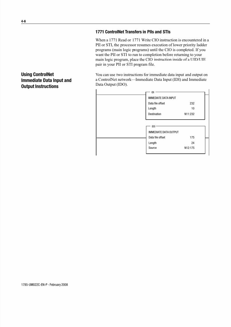
7/27/2019 ControlNet PLC-5 Programmable Controllers User Manual
http://slidepdf.com/reader/full/controlnet-plc-5-programmable-controllers-user-manual 86/148
1785-UM022C-EN-P - February 2008
4-6
1771 ControlNet Transfers in PIIs and STIs
When a 1771 Read or 1771 Write CIO instruction is encountered in a
PII or STI, the processor resumes execution of lower priority ladder
programs (main logic programs) until the CIO is completed. If you
want the PII or STI to run to completion before returning to your
main logic program, place the CIO instruction inside of a UID/UIE
pair in your PII or STI program file.
Using ControlNet
Immediate Data Input and
Output Instructions
You can use two instructions for immediate data input and output on
a ControlNet network—Immediate Data Input (IDI) and Immediate
Data Output (IDO).
IMMEDIATE DATA INPUT
Data file offset
Length
Destination
IDI
IMMEDIATE DATA OUTPUT
Data file offset
Length
Source
ID0
232
10
N11:232
175
24
N12:175
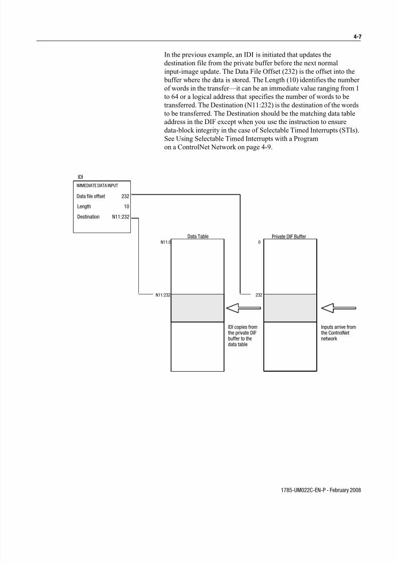
7/27/2019 ControlNet PLC-5 Programmable Controllers User Manual
http://slidepdf.com/reader/full/controlnet-plc-5-programmable-controllers-user-manual 87/148
1785-UM022C-EN-P - February 2008
4-7
In the previous example, an IDI is initiated that updates the
destination file from the private buffer before the next normal
input-image update. The Data File Offset (232) is the offset into the
buffer where the data is stored. The Length (10) identifies the number
of words in the transfer—it can be an immediate value ranging from 1
to 64 or a logical address that specifies the number of words to betransferred. The Destination (N11:232) is the destination of the words
to be transferred. The Destination should be the matching data table
address in the DIF except when you use the instruction to ensure
data-block integrity in the case of Selectable Timed Interrupts (STIs).
See Using Selectable Timed Interrupts with a Program
on a ControlNet Network on page 4-9.
IDI
IMMEDIATE DATA INPUT
Data file offset
Length
Destination
IDI copies fromthe private DIFbuffer to thedata table
Inputs arrive fromthe ControlNetnetwork
N11:232 232
N11:0 0
Data Table Private DIF Buffer
232
10
N11:232

7/27/2019 ControlNet PLC-5 Programmable Controllers User Manual
http://slidepdf.com/reader/full/controlnet-plc-5-programmable-controllers-user-manual 88/148
1785-UM022C-EN-P - February 2008
4-8
An IDO is initiated that updates the private memory output buffer
from the source file before the next normal output-image update. The
Data File Offset (175) is the offset into the buffer where the data is
stored. The Length (24) identifies the number of words in the transfer
or a logical address that specifies the number of words to be
transferred. The Source (N12:175) is the source of the words to betransferred. The Source should be the matching data table address in
the DOF except when you use the instruction to ensure data-block
integrity in the case of Selectable Timed Interrupts (STIs). See Using
Selectable Timed Interrupts with a Program
on a ControlNet Network on page 4-9
For more detailed information about writing ladder programs and
programming ControlNet I/O transfers using Immediate Input (IIN)
and Immediate Output (IOT) instructions, see your programmingsoftware documentation.
IDO
IMMEDIATE DATA OUTPUT
Data file offset
Length
Source
IDO instructioncopies from thedata table to theprivateDOF buffer
Outputs transmittedto the ControlNetnetwork on nextopportunity
N12:175 175
N12:0 0
Data Table Private DOF Buffer
175
24
N12:175

7/27/2019 ControlNet PLC-5 Programmable Controllers User Manual
http://slidepdf.com/reader/full/controlnet-plc-5-programmable-controllers-user-manual 89/148
1785-UM022C-EN-P - February 2008
4-9
Using Selectable Timed
Interrupts with a Program
on a ControlNet Network
You must be careful when using Selectable Timed Interrupts (STIs)
with a program on a ControlNet network.
A Selectable Timed Interrupt (STI) periodically interrupts primary
program execution in order to run a subprogram to completion. If an
STI occurs while a normal ControlNet non-discrete I/O data transfer
or a ControlNet Immediate Data I/O instruction (IDO or IDI) is in
progress and they both operate on the same set of data, the integrity of
that block of data is jeopardized.
To ensure data-block integrity, write your STI routine so that it
operates on its own copy of the data block that it needs. Use
ControlNet Immediate Data I/O instructions (IDO and IDI) within
your STI to copy the needed block of data out to and back from a
temporary location that is different from that used by the normal data
table.
For detailed information about STIs, see your programming software
documentation.
Recovering from Major Fault 200
and 201
A Major Fault with error code 200 and 201 means that the processor
was unable to transmit the scheduled data it is configured to transmit.
This is typically caused by disturbances on the ControlNet channel
because of missing terminators, bad connectors, or noisy conditions.
These disturbances may cause the processor to fall off the network
while its trying to transmit its scheduled data. If you consistently get
these faults, you may want to check and repair the cable.
This fault can also occur when the processor falls behind and did not
have the scheduled data ready to send on time.
Depending on the requirements of the application, you may consider
adding a fault routine to the application to clear an occurrence of a
Major Fault with error code 200 and 201.
For detailed information about creating fault routines, refer to chapter
16 of the Enhanced and Ethernet PLC-5 Programmable Controllers
User Manual, publication 1785-6.5.12.
Note: To monitor for ControlNet noise via ladder logic or HMI,
declare a ControlNet diagnostic file using RSNetWorx software.
Refer to Appendix F: ControlNet Diagnostic File Layout for definitions. You can also monitor for ControlNet noise via RSWho’s
station diagnostics in RSLinx.

7/27/2019 ControlNet PLC-5 Programmable Controllers User Manual
http://slidepdf.com/reader/full/controlnet-plc-5-programmable-controllers-user-manual 90/148
1785-UM022C-EN-P - February 2008
4-10
Notes

7/27/2019 ControlNet PLC-5 Programmable Controllers User Manual
http://slidepdf.com/reader/full/controlnet-plc-5-programmable-controllers-user-manual 91/148
1785-UM022C-EN-P - February 2008
Chapter 5
Monitoring and Troubleshooting
Your ControlNet SystemUsing This Chapter
Using the General Status
Indicators
The general status indicators inform you of the general operational
state of the processor.
Topic Page
Using the general status indicators 5-1
Using the ControlNet status indicators 5-3
Using the Data Highway Plus and Remote I/O Status Indicators 5-5
Monitoring the ControlNet configuration and status 5-5
Using the DH+/RIO Status Indicators 5-6
Indicator Color Description Probable Cause Recommended Action
BATT Red Battery low Battery low Replace battery within 10 days
Off Battery is good Normal operation No action required
BATT
PROC
FORCE
COMM

7/27/2019 ControlNet PLC-5 Programmable Controllers User Manual
http://slidepdf.com/reader/full/controlnet-plc-5-programmable-controllers-user-manual 92/148
1785-UM022C-EN-P - February 2008
5-2
PROC Green(steady)
Processor is in runmode and fullyoperational
Normal operation No act ion required
Green(blinking)
Processor memory isbeing transferred toEEPROM
Normal operation No act ion required
Red(blinking)
Major fault • RSLogix 5download inprogress
• Run-time error
During RSLogix 5 download, this isnormal operation - wait fordownload to complete.
If not during RSLogix 5 download:
• Check major fault bit in statusfile (S:11) for error definition
• Clear fault, correct problem, andreturn to run mode
AlternatingRed andGreen
Processor inFLASH-memoryprogramming mode
Normal operation ifprocessor's FLASHmemory is being
reprogrammed
No action required - allow flashupdate to complete
Red
(steady)
Power cycle withproblem battery
Battery is low,disconnected or notinstalled
Properly replace or install battery(see Chapter 1 for moreinformation)
Red
(steady)
Fault with memoryloss
• New processor
• Invalid ControlNetnetwork address
• Processor hasfailed internaldiagnostics
• Use programming software toclear and initialize memory
• Verify that ControlNet addressswitch is not set to 0
• Install battery (to preservefailure diagnostics), then powerdown, reseat processor andpower up; then reload yourprogram. If you are unable to
reload your program, replace theprocessor. If you are able toreload your program and faultpersists, contact TechnicalSupport at 440.646.6800 todiagnose the problem.
Off Processor is inprogram load or testmode or is notreceiving power
Check power supply andconnections
FORCE Amber(steady)
SFC and/or I/O forcesenabled
Normal operation No act ion required
Amber(blinking)
SFC and/or I/O forcespresent but notenabled
Off SFC and/or I/O forcesnot present
COMM Off No transmission onchannel 0
Normal operation ifchannel is not beingused
Green(blinking)
Transmission onchannel 0
Normal operation ifchannel is beingused
Indicator Color Description Probable Cause Recommended Action

7/27/2019 ControlNet PLC-5 Programmable Controllers User Manual
http://slidepdf.com/reader/full/controlnet-plc-5-programmable-controllers-user-manual 93/148
1785-UM022C-EN-P - February 2008
5-3
Using the ControlNet
Status Indicators
The ControlNet status indicators inform you of the operational state
of the ControlNet network.
Indicator Color Description Probable Cause Recommended Action
I/O Off ControlNet I/O notpresent or notoperating
Normal operation ifChannel 2 not being used
No action required
SteadyGreen
All nodes configuredin the ControlNet maptable present andoperating properly
Normal operation No action required
FlashingGreen/Off
At least one nodeconfigured for theControlNet network not present or notoperating properly
Cable(s) or connector(s)broken or not connected
Repair or replace cable(s) orconnector(s), and reconnect
Destination module(s) bador missing
Repair or replace module(s)
Node(s) not on network Connect node to network
FlashingRed/Off
All nodes configuredfor ControlNet notpresent or notoperating properly
Cable(s) or connector(s)broken or not connected
Repair or replace cable(s) orconnector(s), and reconnect
Nodes not on network Connect nodes to network
I/O
A B
Indicator Color1 Probable Cause Recommended Action
Off Internal diagnostics failed 1. Turn power off, make sure ControlNet addressis not 00, reseat processor, then power up
2. Clear memory and reload your program
3. Replace EEPROM with new program
4. If still an error, replace the processor
No power Check power supply
Steady Red Faulted unit Cycle power or reset unit
If fault persists, contact your Rockwell Automationrepresentative or distributor
FlashingGreen
Normal operation if processor is inFLASH memory program mode
No action required
FlashingRed/Green
The processor's ControlNet addressis above UMAX
Configure the ControlNet network so that UMAX is atleast as high as the processor's ControlNet address.
Set the processor's ControlNet address at or belowUMAX.
AlternatingRed/Green
Self-test No action required
AlternatingRed/Off
Incorrect node configuration Check network address and other ControlNetconfiguration parameters
and
A B
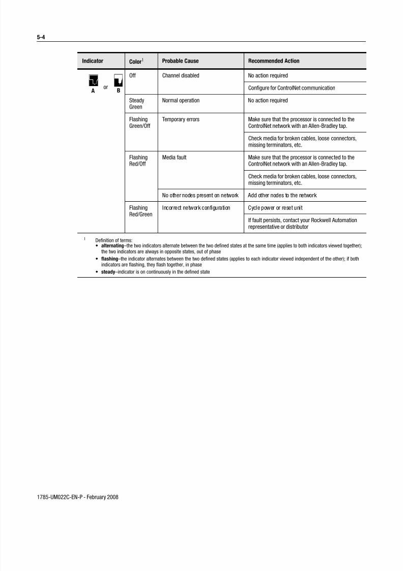
7/27/2019 ControlNet PLC-5 Programmable Controllers User Manual
http://slidepdf.com/reader/full/controlnet-plc-5-programmable-controllers-user-manual 94/148
1785-UM022C-EN-P - February 2008
5-4
Indicator Color1 Probable Cause Recommended Action
Off Channel disabled No action required
Configure for ControlNet communication
SteadyGreen
Normal operation No action required
FlashingGreen/Off
Temporary errors Make sure that the processor is connected to theControlNet network with an Allen-Bradley tap.
Check media for broken cables, loose connectors,missing terminators, etc.
FlashingRed/Off
Media fault Make sure that the processor is connected to theControlNet network with an Allen-Bradley tap.
Check media for broken cables, loose connectors,missing terminators, etc.
No other nodes present on network Add other nodes to the network
FlashingRed/Green
Incorrect network configuration Cycle power or reset unit
If fault persists, contact your Rockwell Automationrepresentative or distributor
1 Definition of terms:• alternating–the two indicators alternate between the two defined states at the same time (applies to both indicators viewed together);
the two indicators are always in opposite states, out of phase
• flashing–the indicator alternates between the two defined states (applies to each indicator viewed independent of the other); if bothindicators are flashing, they flash together, in phase
• steady–indicator is on continuously in the defined state
A Bor

7/27/2019 ControlNet PLC-5 Programmable Controllers User Manual
http://slidepdf.com/reader/full/controlnet-plc-5-programmable-controllers-user-manual 95/148
1785-UM022C-EN-P - February 2008
5-5
Using the DH+/RIO
Status Indicators
Indicator Color Channel Mode Description Probable Cause Recommended Action
Green (steady)
Remote I/OScanner
Active Remote I/O link, alladapter modules arepresent and not faulted
Normaloperation
No action required
Remote I/O Adapter
Communicating withscanner
DH+ Processor is transmittingor receiving on DH+ link
Green(blinkingrapidly orslowly)
Remote I/OScanner
At least one adapter isfaulted or has failed
• Power off atremote rack
• Cable broken
• Restore power to therack
• Repair cable
DH+ No other nodes on network
Red (steady)
Remote I/OScanner Remote I/O Adapter DH+
Hardware fault Hardware error • Turn power off, thenon.
• Check that thesoftwareconfigurationsmatch the hardwareset-up.
• Replace theprocessor.
Red (blinkingrapidly orslowly)
Remote I/OScanner
Faulted adapters detected • Cable notconnected oris broken
• Power off at
remote racks
• Repair cable
• Restore power to
racks
DH+ Bad communication onDH+
Duplicate nodedetected
Correct station address
Off Remote I/OScanner Remote I/O Adapter DH+
Channel offline Channel is notbeing used
Place channel online ifneeded
A Bor

7/27/2019 ControlNet PLC-5 Programmable Controllers User Manual
http://slidepdf.com/reader/full/controlnet-plc-5-programmable-controllers-user-manual 96/148
1785-UM022C-EN-P - February 2008
5-6
Monitoring ControlNet
Configuration and Status
Use the following software packages to monitor ControlNet
configuration and status information.
For information about using these software packages, see the online
help systems for RSNetWorx for ControlNet and RSLogix5 software.
Use: To:
RSNetWorx for ControlNet define ControlNet network parameters, such as:• network update time
• media redundancy
• physical media configuration
• maximum scheduled nodes
• maximum unscheduled nodes
• monitor I/O map entry status
RSLogix5 • monitor ControlNet diagnostic file1
• enter user program files
• create/delete/monitor data table files
• enter module configuration
• enter channel 0, 1A, 1B, and, 3 configuration
• administer passwords and privileges
RSLinx to provide the ControlNet network interfaces to:
• poll the network for active devices
• monitor station diagnostics
1 It is highly recommended that you declare an extended ControlNet diagnostic file (63words) using RSNetWorx. This file will allow you to monitor for noise (via ladder and HMIquery), to monitor the overall health of scheduled connections (words 40 and 41), and tomonitor ControlNet buffer usage.

7/27/2019 ControlNet PLC-5 Programmable Controllers User Manual
http://slidepdf.com/reader/full/controlnet-plc-5-programmable-controllers-user-manual 97/148
1785-UM022C-EN-P - February 2008
Appendix A
Processor Specifications
Backplane Current 1785-L20C15: 2.7A @ 5Vdc1785-L40C15, -L46C15, -L80C15: 3.3A @ 5Vdc
Heat Dissipation 1785-L20C15: 54 BTU/hour1785-L40C15, -L46C15, -L80C15: 59 BTU/hour
Operating Temperature IEC 60068-2-1 (Test Ad, Operating Cold),IEC 60068-2-2 (Test Bd, Operating Dry Heat),IEC 60068-2-14 (Test Nb, Operating Thermal Shock):
0-60oC (32–140oF)
Storage Temperature IEC 60068-2-1 (Test Ab, Un-packaged Non-operating Cold),IEC 60068-2-2 (Test Bc, Un-packaged Non-operating Dry Heat),IEC 60068-2-14 (Test Na, Un-packaged Non-operating Thermal Shock):
–40 to 85oC (–40 to 185oF)
Relative Humidity IEC 60068-2-30 (Test Db, Un-packaged Non-operating Damp Heat):5–95% non condensing
Vibration IEC60068-2-6 (Test Fc, Operating):2g @10–500Hz
Shock IEC60068-2-27:1987, Test Ea (Unpackaged shock, ES#002)Operating - 30gNon-operating - 50g
Emissions CISPR 11:Group 1, Class A
ESD Immunity IEC 61000-4-2:4kV contact discharges
Radiated RF Immunity IEC 61000-4-3:10V/m, 3V/m Broadcast Bands, with 1kHz sine-wave 80% AM from 30MHz to 1000Mhz
EFT/B Immunity IEC 61000-4-4:+2kV at 5kHz on communications ports
Surge Transient Immunity IEC 61000-4-5:
+2kV line-earth(CM)on signal ports
Conducted RF Immunity IEC 61000-4-6:10Vrms with 1kHz sine-wave 80%AM from 150kHzto 30MHz
Enclosure Type Rating None (open style)
Time-of-Day
Clock/Calendar1
Maximum Variations at 60° C: ±5 min per month
Typical Variations at 20° C: ±20 s per month
Timing Accuracy: 1 program scan
Available Cartridges 1785-CHBM ControlNet Hot Backup Cartridge2
(required for each processor used in a hot backup system)
1785-RC Relay Cartridge
Battery Allen-Bradley 1770-XYC
Memory Modules3 • 1785-ME32• 1785-ME64• 1785-M100
I/O Modules Bulletin 1771 I/O, 1794 I/O, 1746 I/O, and 1791 I/Oincluding 8-, 16-, 32-pt, and intelligent modules
1 The clock/calendar will update appropriately each year.2 The 1785-CHBM cannot be used with the 1785-5/60C processor.3 The 1785-ME16 cannot be used with ControlNet PLC-5 processors.4 For more information, refer to publication 1770-4.1, Industrial Automation Wiring and Grounding Guidelines .5 See the Product Certification link a t http://www.ab.com for Declarations of Conformity, Certificates, and other certifica tion details.

7/27/2019 ControlNet PLC-5 Programmable Controllers User Manual
http://slidepdf.com/reader/full/controlnet-plc-5-programmable-controllers-user-manual 98/148
1785-UM022C-EN-P - February 2008
A-2
Hardware Addressing 2-slot• Any mix of 8-pt modules• 16-pt modules must be I/O pairs• No 32-pt modules1-slot• Any mix of 8- or 16-pt modules• 32-pt modules must be I/O pairs1/2-slot—Any mix of 8-,16-, or 32-pt modules
Communication • Serial• DH+• DH using 1785-KA • Remote I/O• ControlNet
Wire Category 24
• Relay Cartridge Wire Category 14
Location 1771-A1B, -A2B, A3B, -A3B1, -A4B chassis; left-most slot
Weight PLC-5/20C15: 3 lbs, 3 oz (1.45 kg)PLC-5/40C15: 3 lbs, 2 oz (1.42 kg)PLC-5/46C15: 3 lbs, 2 oz (1.42 kg)PLC-5/80C15: 3 lbs, 2 oz (1.42 kg)
Keying • Between 40 and 42
• Between 54 and 56Certifications (when product is marked)
UL UL Listed Industrial Control EquipmentCSA CSA Certified Process Control EquipmentCSA CSA Certified Process Control Equipment for Class I, Division 2 Group
A,B,C,D Hazardous Locations
CE5 European Union 89/336/EEC EMC Directive, compliant with:EN 50081-2; Industrial EmissionsEN 50082-2; Industrial ImmunityEuropean Union 73/23/EEC LVD Directive, compliant with:
EN 61131-2; Programmable Controllers
C-Tick 5 Australian Radiocommunications Act, compliant with: AS/NZS 2064; Industrial Emissions
1 The clock/calendar will update appropriately each year.2 The 1785-CHBM cannot be used with the 1785-5/60C processor.3 The 1785-ME16 cannot be used with ControlNet PLC-5 processors.
4 For more information, refer to publication 1770-4.1, Industrial Automation Wiring and Grounding Guidelines .5 See the Product Certification link at http://www.ab.com for Declarations of Conformity, Certificates, and other certification details.

7/27/2019 ControlNet PLC-5 Programmable Controllers User Manual
http://slidepdf.com/reader/full/controlnet-plc-5-programmable-controllers-user-manual 99/148
1785-UM022C-EN-P - February 2008
A-3
PLC-5/20C15 PLC-5/40C15 PLC-5/46C15 PLC-5/80C15
Maximum User Memory Words 16K 48K 1 48K 1 100K 2
Maximum TotalI/O
Any Mix 512 2048 2048 3072
Complimentary 512 in and 512out
2048 in and2048 out
2048 in and2048 out
3072 in and3072 out
Program Scan Time 0.5 ms per K word (bit logic)2 ms per K word (typical)
ControlNet I/O3 Transmission Rate 5M bit/s
Network Update Time (NUT) 2-100 ms (user selectable)
Number of ControlNet Ports 1 (redundant)
Maximum Number of Nodes per Link without a Repeater 48—with 250 m (approx. 820 ft) cable length
Maximum Number of Nodes per Link with Repeaters 99
Maximum Link Cable Length without a Repeater 1,000 m (approximately 3,280 ft)—with 2 nodes500 m (approximately 1,640 ft)—with 32 nodes250 m (approximately 820 ft)—with 48 nodes
Maximum Number of I/O Map Entries 64 96 96 128
Maximum DIF/DOF Size 2000 words 3000 words 3000 words 4000 words
Maximum Link Cable Length with Repeaters 6,000 m (approximately 19,680 ft)—with 2 nodes
3,000 m (approximately 9,840 ft)—typical
Remote I/O andDH+
Transmission Rate 57.6K bit/s
115.2K bit/s
230.4K bit/s
I/O Scan Time (Typical) 10 ms per rack @ 57.6K bit/s
7 ms per rack @ 115.2K bit/s
3 ms per rack @ 230K bit/s
Maximum Number of Remote I/O Racks 3 15 15 23
Maximum Number of Remote I/O Devices 12 60 60 92
Number of Ports Configurable for DH+ or Remote I/O(Adapter or Scanner)
1 2 2 2
Number of Dedicated DH+ Ports 1 0 0 0
Number of Serial Ports 1Number of Coprocessor Ports 1
Maximum Number of MCPs 16
1 The PLC-5/40C15 and -5/46C15 processors have a limit of 32K words per data-table file.2 The PLC-5/80C15 processor has a limit of 56K words per program file and 32 K words per data table file. The PLC-5/80C processor has 64K words of total data
table space.3 For more information, see the ControlNet Cable System Planning and Installation Manual, publication 1786-6.2.1.

7/27/2019 ControlNet PLC-5 Programmable Controllers User Manual
http://slidepdf.com/reader/full/controlnet-plc-5-programmable-controllers-user-manual 100/148
1785-UM022C-EN-P - February 2008
A-4
The following information applies when operating thisequipment in hazardous locations:
Informations sur l’utilisation de cet équipement enenvironnements dangereux:
Products marked “CL I, DIV 2, GP A, B, C, D” are suitablefor use in Class I Division 2 Groups A, B, C, D, HazardousLocations and nonhazardous locations only. Each product issupplied with markings on the rating nameplate indicatingthe hazardous location temperature code. When combining products within a system, the most adverse temperature code(lowest “T” number) may be used to help determine theoverall temperature code of the system. Combinations of equipment in your system are subject to investigation by thelocal Authority Having Jurisdiction at the time of installation.
Les produits marqués "CL I, DIV 2, GP A, B, C, D" neconviennent qu’à une utilisation en environnements deClasse I Division 2 Groupes A, B, C, D dangereux et nondangereux. Chaque produit est livré avec des marquages sur sa plaque d’identification qui indiquent le code detempérature pour les environnements dangereux. Lorsque plusieurs produits sont combinés dans un système, le code detempérature le plus défavorable (code de température le plusfaible) peut être utilisé pour déterminer le code detempérature global du système. Les combinaisonsd’équipements dans le système sont sujettes à inspection par les autorités locales qualifiées au moment de l’installation.
EXPLOSION HAZARD
• Do not disconnect equipmentunless power has been
removed or the area is known
to be nonhazardous.
• Do not disconnect connec-
tions to this equipment unless
power has been removed or
the area is known to be non-
hazardous. Secure any external
connections that mate to this
equipment by using screws,
sliding latches, threaded con-nectors, or other means pro-
vided with this product.
• Substitution of components
may impair suitability for
Class I, Division 2.
• If this product contains batter-
ies, they must only be changed
in an area known to be non-
hazardous.
RISQUE D’EXPLOSION
• Couper le courant ou s’assurer que l’environnement est classé
non dangereux avant de
débrancher l'équipement.
• Couper le courant ou s'assurer
que l’environnement est classé
non dangereux avant de
débrancher les connecteurs.
Fixer tous les connecteurs
externes reliés à cet équipe-
ment à l'aide de vis, loquets
coulissants, connecteurs filetésou autres moyens fournis avec
ce produit.
• La substitution de composants
peut rendre cet équipement
inadapté à une utilisation en
environnement de Classe I,
Division 2.
• S’assurer que l’environne-
ment est classé non dangereux
avant de changer les piles.
WARNING
!
AVERTISSMENT
!

7/27/2019 ControlNet PLC-5 Programmable Controllers User Manual
http://slidepdf.com/reader/full/controlnet-plc-5-programmable-controllers-user-manual 101/148
1785-UM022C-EN-P - February 2008
Appendix B
Processor Status File
S:0 - S:2 Processor status data is stored in data-file 2.
This word of
the status file:
Stores:
S:0 Arithmetic flags
• bit 0 = carry
• bit 1 = overflow
• bit 2 = zero
• bit 3 = sign
S:1 Processor status and flags
S:1/00 RAM checksum is invalid at power-up
S:1/01 Processor in run mode
S:1/02 Processor in test mode
S:1/03 Processor in program mode
S:1/04 Processor uploading to memory module
S:1/05 Processor in download mode
S:1/06 Processor has test edits enabled
S:1/07 Mode select switch in REMOTE position
S:1/08 Forces enabled
S:1/09 Forces present
S:1/10 Processor successfully uploaded to memory module
S:1/11 Performing onl ine programming
S:1/12 Not defined
S:1/13 User program checksum calculated
S:1/14 Last scan of ladder or SFC step
S:1/15 Processor running first program scan or the first scan of the nextstep in an SFC
S:2 Switch setting information
S:2/00 through S:2/05
Channel 1A DH+ station number
S:2/06 Channel 1A DH+ baud rate
0 57.6 kbps
1 230.4 kbps

7/27/2019 ControlNet PLC-5 Programmable Controllers User Manual
http://slidepdf.com/reader/full/controlnet-plc-5-programmable-controllers-user-manual 102/148
1785-UM022C-EN-P - February 2008
B-2 Processor Status File
S:3-10
S:2/07 S:2/08
Not defined
S:2/09 Last state0 outputs are turned off
1 outputs retain last state
S:2/11 S:2/12
I/O chassis addressing
bit 12 bit 11 0 0 illegal 1 0 1/2-slot 0 1 1-slot 1 1 2-slot
S:2/13 S:2/14
Memory module transfer
bit 14 bit 13 0 0 memory module transfers to processormemory
if processor memory is not valid 0 1 memory module does not transfer to
processor memory 1 1 memory module transfers to processormemory
at powerup
S:2/15 Processor memory protection
0 enabled
1 disable
This word of
the status file:
Stores:
This word ofthe status file:
Stores:
S:3 to S:6 Active Node table for channel 1A Word Bits DH+ Station # 3 0-15 00-17 4 0-15 20-37 5 0-15 40-57 6 0-15 60-77
S:7 Global status bits: (See also S:27, S:32, S:33, S:34, and S:35)
• S:7/0-7 rack fault bits for racks 0-7
• S:7/8-15 unused
S:8 Last program scan (in ms)
S:9 Maximum program scan (in ms)
S:10 Minor fault (word 1) See also S:17
S:10/00 Battery is low (replace in 1-2 days)
S:10/01 DH+ active node table has changed
S:10/02 STI delay too short, interrupt program overlap
S:10/03 memory module transferred at power-up

7/27/2019 ControlNet PLC-5 Programmable Controllers User Manual
http://slidepdf.com/reader/full/controlnet-plc-5-programmable-controllers-user-manual 103/148
1785-UM022C-EN-P - February 2008
Processor Status File B-3
S:11
S:10/04 Edits prevent SFC continuing; data table size changed duringprogram mode; reset automatically in run mode
S:10/05 Invalid I/O status file
S:10/06 reserved
S:10/07 No more command blocks exist to execute block-transfers
S:10/08 Not enough memory on the memory module to upload the programfrom the processor
S:10/09 No MCP is configured to run
S:10/10 MCP not allowed
S:10/11 PII word number not in local rack
S:10/12 PII overlap
S:10/13 no command blocks exist to get PII
S:10/14 Arithmetic overflow
This word of
the status file:Stores:
This word of
the status file:Stores:
S:11 major fault word
S:11/00 Corrupted program file (codes 10-19). See major fault codes (S:12).
S:11/01 Corrupted address in ladder program (codes 20-29). See majorfault codes (S:12).
S:11/02 Programming error (codes 30-49). See major fault codes (S:12).
S:11/03 Processor detected an SFC fault (codes (71-79). See major faultcodes (S:12).
S:11/04 Processor detected an error when assembling a ladder program file(code 70); duplicate LBLs found.
S:11/05 Start-up protection fault. The processor sets this major fault bitwhen powering up in Run mode if the user control bit S:26/1 is set.
S:11/06 Peripheral device fault
S:11/07 User-generated fault; processor jumped to fault routine (codes 0-9).See major fault codes (S:12).
S:11/08 Watchdog faulted
S:11/09 System configured wrong (codes 80 - 82, 84 - 88, 200 - 208). Seemajor fault codes (S:12).
S:11/10 Recoverable hardware error
S:11/11 MCP does not exist or is not a ladder or SFC file

7/27/2019 ControlNet PLC-5 Programmable Controllers User Manual
http://slidepdf.com/reader/full/controlnet-plc-5-programmable-controllers-user-manual 104/148
1785-UM022C-EN-P - February 2008
B-4 Processor Status File
S:12 This word stores the following fault codes:
S:11/12 PII file does not exist or is not a ladder file
S:11/13 STI file does not exist or is not a ladder file
S:11/14 Fault routine does not exist or is not a ladder file
S:11/15 Faulted program file does not contain ladder logic
This word of
the status file:Stores:
This
fault
code:
Indicates this fault:
And the fault is:
00-09 Reserved for user-defined fault codes.
You can use user-defined fault codes to identify different types of faults or error conditions in yourprogram by generating your own recoverable fault. To use these fault codes, choose an input conditionthat decides whether to jump to a fault routine file, then use the JSR instruction as the means to jump tothe fault routine file.
To use the JSR instruction, enter the fault code number 0-9 (an immediate value) as the first inputparameter of the instruction. Any other input parameters are ignored (even if you have an SBR instructionat the beginning of your fault routine file. You cannot pass parameters to the fault routine file usingJSR/SBR instructions).
You do not have to use the user-defined fault codes to generate your own fault. If you program a JSR withno input parameters, the processor will write a zero to the Fault Code field. The purpose of using theuser-defined fault codes is to allow you to distinguish among different types of faults or error codesbased on the 0-9 fault code numbers.
When the input condition is true, the processor copies the fault code number entered as the first input
parameter of the JSR instruction into word 12 of the processor status file (S:12), which is the Fault Codefield. The processor sets a Major Fault S:11/7 “User-Generated Fault.” The processor then faults unlessyou clear the Major Fault word (S:11) or the specific fault bit via ladder logic in the fault routine.
Recoverable:
the fault routine can instructthe processor to clear thefault and then resumescanning the program.
A fault routine executeswhen any of these faultsoccur.

7/27/2019 ControlNet PLC-5 Programmable Controllers User Manual
http://slidepdf.com/reader/full/controlnet-plc-5-programmable-controllers-user-manual 105/148
1785-UM022C-EN-P - February 2008
Processor Status File B-5
10 Run-time data table check failed Recoverable:
the fault routine can instructthe processor to clear thefault and then resumescanning the program.
A fault routine executeswhen any of these faultsoccur.
11 Bad user program checksum
12 Bad integer operand type, restore new processor memory file
13 Bad mixed mode operation type, restore new processor memory file
14 Not enough operands for instruction, restore new processor memory file
15 Too many operands for instructions, restore new processor memory file
16 Corrupted instruction, probably due to restoring an incompatible processor memory file (bad opcode)
17 Can’t find expression end; restore new processor memory file
18 Missing end of edit zone; restore new processor memory file
19 Download aborted
20 You entered too large an element number in an indirect address
21 You entered a negative element number in an indirect address
22 You tried to access a non-existent program file
23 You used a negative file number, you used a file number greater than the number of existing files, or youtried to indirectly address files 0, 1, or 2
24 You tried to indirectly address a file of the wrong type Recoverable
30 You tried to jump to one too many nested subroutine files Non-recoverable:
the fault routine will beexecuted but cannot clearmajor fault bit 2.
31 You did not enter enough subroutine parameters
32 You jumped to an inval id (non-ladder) f ile
33 You entered a CAR routine file that is not 68000 code
34 You entered a negative preset or accumulated value in a timer instruction Recoverable
35 You entered a negative time variable in a PID instruction
36 You entered an out-of-range setpoint in a PID instruction
37 You addressed an invalid module in a block-transfer, immediate input, or immediate output instruction
38 You entered a RET instruction from a non-subroutine file Non-recoverable
the fault routine will beexecuted but cannot clear
major fault bit 2.
39 FOR instruction with missing NXT
40 The control file is too small for the PID, BTR, BTW, or MSG instruction Recoverable
This
fault
code:
Indicates this fault:
And the fault is:

7/27/2019 ControlNet PLC-5 Programmable Controllers User Manual
http://slidepdf.com/reader/full/controlnet-plc-5-programmable-controllers-user-manual 106/148
1785-UM022C-EN-P - February 2008
B-6 Processor Status File
41 NXT instruction with missing FOR Non-recoverable
the fault routine will beexecuted but cannot clearmajor fault bit 2.
42 You tried to jump to a non-existent label
43 File is not an SFC
44 Error using SFR. This error occurs if:
• you tried to reset into a simultaneous path
• you specified a step reference number that is not found or is not tied to a step (it is a transition)
• the previous SFR to a different step is not complete
45 Invalid channel number entered Recoverable
46 Length operand of IDI or IDO instruction is greater than the maximum allowed
47 SFC action overlap. An action was still active when the step became re-activated Non-recoverable
48-69 Reserved Recoverable
70 The processor detected duplicate labels
71 The processor tried to start an SFC subchart that is already running
72 The processor tried to stop an SFC subchart that isn’t running
73 The processor tried to start more than the allowed number of subcharts
74 SFC file error detected
75 The SFC has too many act ive functions
76 SFC step loops back to itself.
77 The SFC references a step, transition, subchart, or SC file that is missing, empty or too small
78 The processor cannot continue to run the SFC after power loss
79 You tried to download an SFC to a processor that cannot run SFCs
80 You have an I/O configuration error Recoverable
81 You illegally set an I/O chassis backplane switch by setting both switch 4 and 5 on
82 Illegal cartridge type for selected operation. This error also occurs if the processor doesn’t have amemory module, but the backplane switches are set for a memory module. Make sure the backplaneswitches are correct (set switch 6 ON and switch 7 OFF if the processor doesn’t have a memory module).
This
fault
code:
Indicates this fault:
And the fault is:

7/27/2019 ControlNet PLC-5 Programmable Controllers User Manual
http://slidepdf.com/reader/full/controlnet-plc-5-programmable-controllers-user-manual 107/148
1785-UM022C-EN-P - February 2008
Processor Status File B-7
83 User watchdog fault Recoverable
84 Error in user-configured adapter mode block-transfer
85 Memory module bad
86 Memory module is incompatible with host
87 Scanner rack list overlap
88 Scanner channels are overloading the remote I/O buffer; too much data for the processor to process. Ifyou encounter fault code 88, be sure you followed proper design guidelines. Specifically, make sure you:
• group together 1/4-racks and 1/2-racks of each logical rack. Do not intersperse these with other rack numbers
• if using complementary I/O addressing, treat complementary rack addresses individually whengrouping racks; primary rack numbers are separate from complement rack numbers
90 Sidecar module extensive memory test failed. Call your Rockwell Automation representative for service
91 Sidecar module undefined message type
92 Sidecar module requesting undefined pool
93 Sidecar module illegal maximum pool size
94 Sidecar module illegal ASCII message
95 Sidecar module reported fault, which may be the result of a bad sidecar program or of a hardware failure
96 Sidecar module not physically connected to the PLC-5 processor
97 Sidecar module requested a pool size that is too small for PC3 command (occurs at power-up)
98 Sidecar module first/last 16 bytes RAM test failed
99 Sidecar module-to-processor data transfer faulted
100 Processor-to-sidecar module transfer failed
101 Sidecar module end of scan transfer failed
102 The file number specified for raw data transfer through the sidecar module is an illegal value
103 The element number specified for raw data transfer through the sidecar module is an illegal value
104 The size of the transfer requested through the sidecar module is an illegal size
105 The offset into the raw transfer segment of the sidecar module is an illegal value
106 Sidecar module transfer protection violation; for PLC-5/26, -5/46, and -5/86 processors only
200 ControlNet scheduled output data missed.
The processor is unable to transmit the scheduled data it is configured to transmit.
Recoverable
Check your network formissing terminators or othersources of electrical noise(see the Industrial Automation Wiring andGrounding Guidelines,publication 1770-4.1)
This
fault
code:
Indicates this fault:
And the fault is:
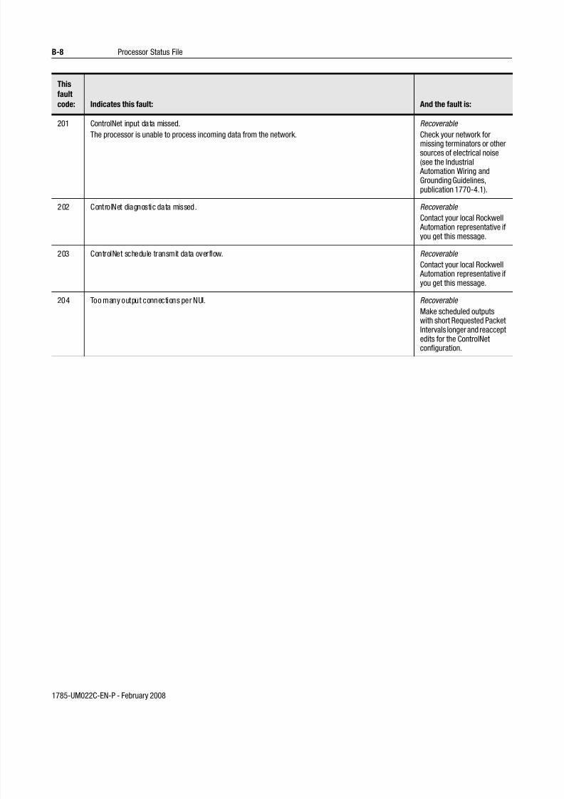
7/27/2019 ControlNet PLC-5 Programmable Controllers User Manual
http://slidepdf.com/reader/full/controlnet-plc-5-programmable-controllers-user-manual 108/148
1785-UM022C-EN-P - February 2008
B-8 Processor Status File
201 ControlNet input data missed.
The processor is unable to process incoming data from the network.
Recoverable
Check your network formissing terminators or othersources of electrical noise(see the Industrial Automation Wiring andGrounding Guidelines,publication 1770-4.1).
202 ControlNet diagnostic data missed. Recoverable
Contact your local Rockwell Automation representative ifyou get this message.
203 ControlNet schedule transmit data overflow. Recoverable
Contact your local Rockwell Automation representative ifyou get this message.
204 Too many output connections per NUI. Recoverable
Make scheduled outputswith short Requested PacketIntervals longer and reacceptedits for the ControlNetconfiguration.
This
fault
code:
Indicates this fault:
And the fault is:

7/27/2019 ControlNet PLC-5 Programmable Controllers User Manual
http://slidepdf.com/reader/full/controlnet-plc-5-programmable-controllers-user-manual 109/148
1785-UM022C-EN-P - February 2008
Processor Status File B-9
205 ControlNet configuration exceeds processor bandwidth.
IMPORTANT: Scheduled connections will be closed. You must cycle power, save with RSNetWorx,or download the program to reopen the connections.
Because the configuration software is unable to accurately predict all the resources that the processorwill require to execute your ControlNet configuration software (based on the relative loading on theprocessor), this fault code is used if the processor determines that your configuration (typically when youaccept Channel 2 edits) exceeds the processor’s available bandwidth.
Typical causes of this error code include:
• receiving data from the ControlNet network faster than the ControlNet PLC-5 processor can parse it
• performing I/O updates too frequently
• performing immediate ControlNet I/O ladder instructions too frequently
See S:74 and S:75 for additional information.
Recoverable
Reduce the number ofControlNet I/O map tableentries. Possible ways:
• using a discrete rack connection instead ofmultiple discrete moduleconnections
• combining multiple I/Oracks into a single I/Orack
• putting peer-to-peer datain contiguous blocks inthe data table so that lesssend and receivescheduled messages are
requiredIncrease your Network Update Time and/or increasethe Requested PacketIntervals for scheduled datatransfers in your I/O maptable.
Increase your ladderprogram scan by eitheradding more logic or byincreasing theCommunications Time Slice(S:77).
Reduce the number orfrequency of immediate
ControlNet I/O ladderinstructions that areperformed.
206 This error code is reserved. Contact your local Rockwell Automation representative ifyou get this message.
207 This error code is reserved. Contact your local Rockwell Automation representative ifyou get this message.
208 Too many pending ControlNet I/O connections. Recoverable
Delete one or more I/O maptable entries and reaccept
edits for the ControlNetconfiguration.
230 System attempted transition to Run mode with processor in Invalid backup state. Change from the Invalid
backup state to the No
Control backup state before
transitioning into Run mode.
Refer to the Invalid backup
state troubleshooting table
later in this chapter.
This
fault
code:
Indicates this fault:
And the fault is:

7/27/2019 ControlNet PLC-5 Programmable Controllers User Manual
http://slidepdf.com/reader/full/controlnet-plc-5-programmable-controllers-user-manual 110/148
1785-UM022C-EN-P - February 2008
B-10 Processor Status File
231 Bypassed qualification (may occur during race condition when both processors attempt to go into Run
mode at the same time).
Transition the PLC-5
processors into Run mode
one at a time.
232 Both processors attempted to be primaries. Check all media for broken
cables, loose connectors,
missing terminators, etc.
233 ControlNet configuration invalid on transition into Run mode. Reconfigure the ControlNet
channel.
234 Failed Qualification. Refer to the qualification
major faults troubleshooting
table later in this chapter.
235 Illegal invalid backup state Cycle power to the
processor. If the fault
reoccurs, contact Rockwell
Automation Technical
Support at 440-646-6800
236 Illegal No Control backup state Cycle power to the
processor. If the fault
reoccurs, contact Rockwell
Automation Technical
Support at 440-646-6800
237 Illegal Primary/Secondary backup state Cycle power to the
processor. If the fault
reoccurs, contact Rockwell
Automation Technical
Support at 440-646-6800
238 Incompatible firmware revisions Install the same series and
revision of firmware into
both hot backup PLC-5
processors
239 ControlNet keeper mismatch Use RSNetworx to make the
PLC-5 processor a valid
keeper
This
fault
code:
Indicates this fault:
And the fault is:

7/27/2019 ControlNet PLC-5 Programmable Controllers User Manual
http://slidepdf.com/reader/full/controlnet-plc-5-programmable-controllers-user-manual 111/148
1785-UM022C-EN-P - February 2008
Processor Status File B-11
S:13-S:24
This word of
the status file:
Stores:
S:13 Program file where fault occurred
S:14 Rung number where fault occurred
S:15 VME status file
S:16 I/O status File
S:17 Minor fault (word 2) See also S:10.
S:17/00 BT queue ful l to remote I/O
S:17/01 Queue full - channel 1A; maximum remote block-transfers used
S:17/02 Queue full - channel 1B; maximum remote block-transfers used
S:17/03 Queue full - channel 2A; maximum remote block-transfers used
S:17/04 Queue full - channel 2B; maximum remote block transfers used
S:17/05 No modem on serial port
S:17/06 • Remote I/O rack in local rack table or
• Remote I/O rack is greater than the image size. This fault can alsobe caused by the local rack if the local rack is set for octal densityscan and the I/O image tables are smaller than 64 words (8 racks)each.
S:17/07 Firmware revision for channel pairs 1A/1B or 2A/2B does not matchprocessor firmware revision
S:17/08 ASCII instruction error
S:17/09 Duplicate node address
S:17/10 DF1 master pol l list error
S:17/11 Protected processor data table element violation
S:17/12 Protected processor file violation
S:17/13 Using al l 32 ControlNet MSGs
S:17/14 Using all 32 ControlNet 1771 CIOs
S:17/15 Using all 8 1794 ControlNet FLEX I/O CIOs
S:18 Processor clock year
S:19 Processor clock month
S:20 Processor clock day
S:21 Processor clock hour
S:22 Processor clock minute

7/27/2019 ControlNet PLC-5 Programmable Controllers User Manual
http://slidepdf.com/reader/full/controlnet-plc-5-programmable-controllers-user-manual 112/148
1785-UM022C-EN-P - February 2008
B-12 Processor Status File
S:26-S:35
S:23 Processor clock second
S:24 Indexed addressing offset
S:25 Reserved
This word of
the status file:
Stores:
This word of
the status file:
Stores:
S:26 User control bits
S:26/00 Restart/continuous SFC: when reset, processor restarts at first step in SFC. When
set, processor continues with active step after power loss or change to RUN
S:26/01 Start-up protection after power loss: when reset, no protection. When set,processor sets major fault bit S:11/5 when powering up in run mode.
S:26/02 Define the address of the local rack: when reset, local rack address is 0. When set,local rack address is 1.
S:26/03 Set complementary I/O (series A only): when reset, complementary I/O is notenabled. When set, complementary I/O is enabled.
S:26/04 Local block-transfer compatibility bit: when reset, normal operation. When set,eliminates frequent checksum errors to certain BT modules.
S:26/05 PLC-3 scanner compatibility bit: when set (1), adapter channel response delayed by1 ms; when reset (0) operate in normal response time.
S:26/06 Data table-modification inhibit bit. When set (1), user cannot edit the data table ormodify forces while the processor keyswitch is in the RUN position. You control thisbit with your programming software
S:26/07 through S:26/15
Reserved
S:27 Rack control bits: (See also S:7, S:32, S:33, S:34, and S:35)
• S:27/0-7 - - I/O rack inhibit bits for racks 0-7
• S:27/8-15 - - I/O rack reset bits for racks 0-7
S:28 Program watchdog setpoint
S:29 Fault routine file
S:30 STI setpoint
S:31 STI file number
S:32 Global status bits: (See also S:7, S:27, S:33, S:34, and S:35)
• S:32/0-7 rack fault bits for racks 10-17 (octal)
• S:32/8-15 unused

7/27/2019 ControlNet PLC-5 Programmable Controllers User Manual
http://slidepdf.com/reader/full/controlnet-plc-5-programmable-controllers-user-manual 113/148
1785-UM022C-EN-P - February 2008
Processor Status File B-13
Important: Setting inhibit bits in the processor status file (S:27,
S:33, or S:35) does not update inhibit bits in the I/O
status file.
S:36-S:78
S:33 Rack control bits: (See also S:7, S:27, S:32, S:34, and S:35)
• S:33/0-7 I/O rack inhibit bits for racks 10-17
• S:33/8-15 I/O rack reset bits for racks 10-17
S:34 Global status bits: (See also S:7, S:27, S:32, S:33, and S:35)
• S:34/0-7 rack fault bits for racks 20-27 (octal)
• S:34/8-15 unused
S:35 Rack control bits: (See also S:7, S:27, S:32, S:33, and S:34)
• S:35/0-7 I/O rack inhibit bits for racks 20-27
• S:35/8-15 I/O rack reset bits for racks 20-27
This word of
the status file:
Stores:
This word of
the status file:
Stores:
S:36 - S:45 Reserved
S:46 PII program file number
S:47 PII module group
S:48 PII bit mask
S:49 PII compare value
S:50 PII down count
S:51 PII changed bit
S:52 PII events since last interrupt
S:53 STI scan time (in ms)
S:54 STI maximum scan time (in ms)
S:55 PII last scan time (in ms)
S:56 PII maximum scan time (in ms)
S:57 User program checksum
S:58 Reserved
S:59 Extended-local I/O channel discrete transfer scan (in ms)
S:60 Extended-local I/O channel discrete maximum scan (in ms)
S:61 Extended-local I/O channel block-transfer scan (in ms)
S:62 Extended-I/O channel maximum block-transfer scan (in ms)
S:63 Protected processor data table protection file number

7/27/2019 ControlNet PLC-5 Programmable Controllers User Manual
http://slidepdf.com/reader/full/controlnet-plc-5-programmable-controllers-user-manual 114/148
1785-UM022C-EN-P - February 2008
B-14 Processor Status File
S:64 The number of remote block-transfer command blocks being used by channel pair1A/1B.
S:65 The number of remote block-transfer command blocks being used by channel pair2A/2B.
S:66 Reserved.
S:68 Installed memory card type. The four most-significant bits indicate memory cardtype:
Value: Memory card type:
0 No memory card installed 1 1785-ME16 installed 2 1785-ME32 installed 3 1785-ME64 installed 4 1785-ME100 installed 5 1785-CHBM installed 6 1785-RC installed
7-15 ReservedWhen the 1785-RC module is installed, the eight least-significant bits indicate thememory card’s status: Bit: Is set when:
3 the 1785-RC memory card is installed in the processor 2 contact is detected closed. The bit resets when contact is detected open 1 the relay is driven open. The bit resets when the relay is closed. 0 120Vac is present on the memory card. The bit resets when 120Vac is
not present on the card. When any other memory card is installed, the bits are undefined
S:72 ControlNet node number of this processor.
S:73 ControlNet PLC-2 compatibility file
When a PLC-2 command is received from the ControlNet network, the processor
uses this file number. The PLC-2 file number must be between 3 and 999, inclusive.
S:74 Time (in mill iseconds) between iterations of the ControlNet subsystem diagnostics
When this value exceeds 2000, the processor may major fault with error code 205.See Appendix E, “Fault Codes”.
S:75 Maximum amount of time (in mill iseconds) between iterations of the ControlNetsubsystem diagnostics
S:76 Number of slots in processor-resident local rack
0 Illegal 1 4 slots 2 12 slots 3 8 slots 4 16 slots
S:77 Communication time slice for communication housekeeping functions ( in ms)
S:78 MCP I/O update disable bits
Bit 0 for MCP A Bit 1 for MCP B etc.
This word of
the status file:
Stores:

7/27/2019 ControlNet PLC-5 Programmable Controllers User Manual
http://slidepdf.com/reader/full/controlnet-plc-5-programmable-controllers-user-manual 115/148
1785-UM022C-EN-P - February 2008
Processor Status File B-15
S:79-S127
This word of
the status file:
Stores:
S:79 MCP inhibit bitsBit 0 for MCP A Bit 1 for MCP B etc.
S:80-S:127 MCP file number MCP scan time (in ms) MCP max scan time (in ms)
The above sequence applies to each MCP; therefore, each MCP has3 status words.
For example, word 80: file number for MCP A word 81: scan time for MCP A word 82: maximum scan time for MCP A word 83: file number for MCP B word 84: scan time for MCP B
etc.

7/27/2019 ControlNet PLC-5 Programmable Controllers User Manual
http://slidepdf.com/reader/full/controlnet-plc-5-programmable-controllers-user-manual 116/148
1785-UM022C-EN-P - February 2008
B-16 Processor Status File
Notes

7/27/2019 ControlNet PLC-5 Programmable Controllers User Manual
http://slidepdf.com/reader/full/controlnet-plc-5-programmable-controllers-user-manual 117/148
1785-UM022C-EN-P - February 2008
Appendix C
ControlNet Instruction Set
For detailed information about the instruction set for programmingPLC-5 processors, see the Enhanced and Ethernet PLC-5
Programmable Controllers User Manual, publication 1785-6.5.12,
and the PLC-5 Instruction Set Reference, publication 1785-6.1.
ControlNet I/O Transfer Instruction
Message Instructions on a ControlNet Network
Instruction Description
ControlNet I/O TransferCT
Status Bits TO–Time-Out Bit EW–Enabled-Waiting Bit CO–Continuous Bit ER–Error Bit DN–Done Bit ST–Start Bit EN–Enable Bit
If the input conditions go from false to true, the data istransferred according to the instruction parameters you setwhen you enter the ControlNet I/O transfer instruction.
The Control Block (CT21:50) contains status and instructionparameters.
You cannot use N (integer) control blocks on theControlNet network.
For continuous CIOs, condition the rung to be true for onlyone scan.
Instruction Description
MessageMSG
Status Bits TO–Time-Out Bit EW–Enabled-Waiting Bit CO–Continuous Bit ER–Error Bit DN–Done Bit ST–Start Bit EN–Enable Bit
NC–No Cache Bit
If the input conditions go from false to true, the data istransferred according to the instruction parameters you setwhen you enter the message instruction. The Control Block (MG10:10) contains status and instruction parameters.
You cannot use N (integer) control blocks on the ControlNetnetwork.
For continuous MSGs, condition the rung to be true for onlyone scan.
CIO
CNET I/O TRANSFER
Control block CT21:50
MSG
SEND/RECEIVE MESSAGE
Control block MG10:10

7/27/2019 ControlNet PLC-5 Programmable Controllers User Manual
http://slidepdf.com/reader/full/controlnet-plc-5-programmable-controllers-user-manual 118/148
1785-UM022C-EN-P - February 2008
C-2 ControlNet Instruction Set
Immediate Data I/O Instructions
Immediate I/O Execution Times
Instruction Description
Immediate Data
InputIDI
If the input conditions are true, an immediate data input is initiated that
updates the destination file from the private buffers before the next normalinput-image update. The Data file offset (232) is where the data is stored.The Length (10) identifies the number of words in the transfer–it can be animmediate value ranging from 1 to 64 or a logical address that specifies thenumber of words to be transferred. The Destination (N11:232) is thedestination of the words to be transferred. The Destination should be thematching data-table address in the DIF except when you use the instructionto ensure data-block integrity in the case of Selectable Times Interrupts(STIs). See page 4-8 in the Using ControlNet IMmediate Data Input andOutput Instructions section.
Immediate DataOutput IDO
If the input conditions are true, an immediate data output is initiated thatupdates the private memory output buffers from the source file before thenext normal output-image update. The Data file offset (175) is the offset intothe buffer where the data is stored. The Length (24) identifies the number ofwords in the transfer–it can be an immediate value ranging from 1 to 64 ora logical address that specifies the number of words to be transferred. TheSource (N12:175) is the source of the words to be transferred. The Sourceshould be the matching data-table address in the DOF except when you usethe instruction to ensure data-block integrity in the case of SelectableTimed Interrupts (STIs). See page 4-8 in the Using ControlNet ImmediateData Input and Output Instructions section.
Instruction: Processor:Execution Time (μs)
Words of MemoryTrue: False:
INN - Immediate Input PLC-5/20 C15
PLC-5/40C15, -5/46C15 and -5/80C15
389
347
1.1 2
IOT - Immediate Output PLC-5/20 C15
PLC-5/40C15, -5/46C15 and -5/80C15
323+(14.5 x dis)+(6.7 x DOF)
330+(27.5 x dis)+(13.25 x DOF)
1.1 2
IDI - Immediate Data
Input
PLC-5/20 C15
PLC-5/40C15, -5/46C15 and -5/80C15
538+(0.65 x words)
488+(0.65 x words)
1.1 4-7
IDO - Immediate Data
Output
PLC-5/20 C15
PLC-5/40C15, -5/46C15 and -5/80C15
286+(1.23 x words)+(14.5 x
DOF)+(6.7 x dis)
270+(1.6 x words)+(27.5 x
DOF)+(13.25 x dis)
1.1 4-7
words - IDI or IDO transfer length
dis - Total number of ControlNet connections using the discrete Output image file
DOF - Total number of ControlNet connections using the Data Output File
IDIIMMEDIATE DATA INPUT
Data file offset
Length
232
10
Destination N11:232
IDO
IMMEDIATE DATA OUTPUT
Data file offset
Length
175
24
Source N12:175

7/27/2019 ControlNet PLC-5 Programmable Controllers User Manual
http://slidepdf.com/reader/full/controlnet-plc-5-programmable-controllers-user-manual 119/148
1785-UM022C-EN-P - February 2008
Appendix D
ControlNet I/O Map-Entry
Status Words andError Codes
I/O Map-Entry
Status Words
The ControlNet status file is an integer data-table file that you specify
and configure with the I/O map for scheduled-I/O usage. It contains
status information about all of the ControlNet network’s scheduled
I/O connections. Each I/O map-table entry has a status-file offset field
pointing to three status words associated with the connection.
0000102003040500607080091011120131415
0000102003040500607080091011120131415
0000102003040500607080091011120131415
First Word
Immediate Inhibit Bit
PCSC Overflow Bit
PCSC New Data Bit
PCSC Enable Bit
Run Mode Data
Underrun
Data
Overrun
Reserved
Reserved
Data Invalid Bit
Connection Error Bit
Reset
Bit
Inhibit Bit
Error Messages
System Bits
User Bits
For critical I/O points, always condition your logic with bits 8 and 9 of the first ControlNet status word.

7/27/2019 ControlNet PLC-5 Programmable Controllers User Manual
http://slidepdf.com/reader/full/controlnet-plc-5-programmable-controllers-user-manual 120/148
1785-UM022C-EN-P - February 2008
D-2 ControlNet I/O Map-Entry Status Words and Error Codes
The following table explains the bits in the first word of the
ControlNet I/O status file:
Bit Number Description Use
00 Reset Bit Set this bit to put the associated connection into PROGRAM mode, even if the processor is inRun mode.
Clear this bit to set the mode of the associated connection according to the processor’s mode.
This bit has no effect for 1771 block transfer modules.
01 Inhibit Bit Set this bit to perform an orderly shutdown of the associated connection. If the target node isa ControlNet adapter, the adapter will go into idle mode. The processor will not attempt toreopen the connection as long as this bit is set. The processor will also set the Data Invalid Bitand Connection Error Bit.
Clear this bit to allow the processor to attempt to open the associated connection.
02 PCSC Enable Bit Set this bit to enable Process Control Sample Complete for the associated I/O map entry.
Clear this bit to disable Process Control Sample Complete for the associated I/O map entry.
03 PCSC New Data Bit The processor sets this bit when the PCSC Enable Bit is set and new data arrives from the
associated connection.Clear this bit when you are finished processing the current sample of data.
04 PCSC Overflow Bit The processor sets this bit when the PCSC Enable Bit and the PCSC New Data Bits are set andnew data arrives from the associated connection. This means that PCSC data is arriving fasterthan your ladder program is processing it.
Clear this bit after you modify your ladder program to handle the incoming PCSC data.
05 Immediate Inhibit Bit Set this bit to immediately stop communicating on the associated connection. This has thesame effect as if you disconnected the target node from the ControlNet network. If the targetnode is a ControlNet adapter and the adapter is setup for Processor Restart Lockout, theadapter will go into Processor Restart Lockout mode. The processor will not attempt to reopenthe connection as long as this bit is set. The processor will also set the Data Invalid Bit andConnection Error Bit.
Clear this bit to allow the processor to attempt to open the associated connection.
08 Data Invalid Bit The processor sets this bit when data is not received from the associated target node. Theerror code in second and third words of the ControlNet I/O status tells you why the data isinvalid. Also, if either the Inhibit Bit or Immediate Inhibit Bit is set, the Data Invalid Bit will beset.
The processor clears this bit when valid data is received from the associated target node. Inyour program, make sure that this bit is clear before you use the associated data.
09 Connection Error Bit The processor sets this bit when the associated connection is not made to the target node.The error code in second and third words of the ControlNet I/O status tells you why theconnection is not made. Also, if either the Inhibit Bit or Immediate Inhibit Bit is set, theConnection Invalid Bit will be set.
The processor clears this bit when the associated connection is made to the target node.
10 Data Underrun This bit it set whenever the length of data received for the associated connection is smaller
than expected. The Data Invalid Bit will also set if the length of data received is less than thevalue configured in the Input Data Size field for the connection in RSNetworx.
11 Data Overrun This bit it set whenever the length of data received for the associated connection is larger than
expected. The Data Invalid Bit will not be set.
15 Run Mode This bit it set to give the Run/Idle status of the target device for connections that support
Run/Idle notification (such as Peer-to-Peer Receive Data connections).
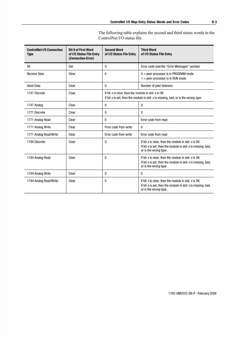
7/27/2019 ControlNet PLC-5 Programmable Controllers User Manual
http://slidepdf.com/reader/full/controlnet-plc-5-programmable-controllers-user-manual 121/148
1785-UM022C-EN-P - February 2008
ControlNet I/O Map-Entry Status Words and Error Codes D-3
The following table explains the second and third status words in the
ControlNet I/O status file.
ControlNet I/O Connection
Type
Bit 9 of First Word
of I/O Status File Entry
(Connection Error)
Second Word
of I/O Status File Entry
Third Word
of I/O Status File Entry
All Set 0 Error code (see the “Error Messages” section)
Receive Data Clear 0 0 = peer processor is in PROGRAM mode
1 = peer processor is in RUN mode
Send Data Clear 0 Number of peer listeners
1747 Discrete Clear If bit x is clear, then the module in slot x is OK.
If bit x is set, then the module in slot x is missing, bad, or is the wrong type.
1747 Analog Clear 0 0
1771 Discrete Clear 0 0
1771 Analog Read Clear 0 Error code from read
1771 Analog Write Clear Error code from write 0
1771 Analog Read/Write Clear Error code from write Error code from read
1794 Discrete Clear 0 If bit x is clear, then the module in slot x is OK.
If bit x is set, then the module in slot x is missing, bad,or is the wrong type.
1794 Analog Read Clear 0 If bit x is clear, then the module in slot x is OK.
If bit x is set, then the module in slot x is missing, bad,or is the wrong type.
1794 Analog Write Clear 0 0
1794 Analog Read/Write Clear 0 If bit x is clear, then the module in slot x is OK.
If bit x is set, then the module in slot x is missing, bad,or is the wrong type.

7/27/2019 ControlNet PLC-5 Programmable Controllers User Manual
http://slidepdf.com/reader/full/controlnet-plc-5-programmable-controllers-user-manual 122/148
1785-UM022C-EN-P - February 2008
D-4 ControlNet I/O Map-Entry Status Words and Error Codes
Error Codes The following is a list of ControlNet error codes, messages, possible
causes, and possible corrective actions. These errors can originate in
either the PLC-5 programmable controller or the target device:
Decimal
Code
Hex. Code Error Message Explanation/Possible Cause(s) Possible Corrective Action(s)
VARIOUS VARIOUS CONFIGURATION DATA CORRUPTED
The ControlNet configuration iscorrupted.
Reenter the map entry that is failing.
Reenter the ladder instruction that isfailing.
1 0x0001 CONNECTION FAILED The ControlNet cable from theoriginating node to the target node isbroken or disconnected.
Fix and/or reconnect the ControlNetcable.
The target node is not powered. Supply power to the target node.
The target’s node number is greaterthan SMAX.
Reconfigure the ControlNet network so that the target’s node number isless than or equal to SMAX.
5 0x0005 UNKNOWN DESTINATION ADDRESS
The slot addressed does not exist. Use a rack with more slots.
Correct the I/O map table.
The map table is corrupted. Reenter the I/O map entry that isfailing.
The target node of the MSGinstruction is not a processor or thetarget node of the CIO instruction isnot the correct I/O adapter.
Edit the ladder program so that thecorrect target node is used.
Replace the target node with the
correct type of node.
12 0x000C OBJECT IN WRONG STATE The target Scheduled Peer Outputmap entry is inhibited.
Clear the inhibit and immediateinhibit bits for the target ScheduledPeer Output map entry.
14 0x000E ATTRIBUTE CANNOT BE SET A CIO instruction attempted to set anattribute that cannot be set at thedestination module. For example, aCIO tried to send safe-state data to aFlex module that does not supportsafe-state data.
Insert a module that can have thisattribute set into the correct slot.
Edit the ladder program so that itdoes not attempt to set thisattribute.
19 0x0013 NOT ENOUGH DATA The transfer length is zero. Increase the transfer length.
The processor data table is too smallto hold the data to be transferred.
Increase the size of the data table toaccommodate the transfer length.
21 0x0015 TOO MUCH DATA The transfer length is too large. Decrease the transfer length.

7/27/2019 ControlNet PLC-5 Programmable Controllers User Manual
http://slidepdf.com/reader/full/controlnet-plc-5-programmable-controllers-user-manual 123/148
1785-UM022C-EN-P - February 2008
ControlNet I/O Map-Entry Status Words and Error Codes D-5
38 0x0026 INVALID DESTINATION ADDRESS SIZE
The map table is corrupted. Reenter the I/O map entry that isfailing.
The target node of the MSGinstruction is not a processor or thetarget node of the CIO instruction isnot the correct I/O adapter.
Edit the ladder program so that thecorrect target node is used.
Replace the target node with thecorrect type of node.
256 0x0100 CONNECTION IN USE The connection at the target node isalready in use.
No action is required. Theconnection can be re-establishedafter the target node times out theold connection.
262 0x0106 CONNECTION USED BY OTHERNODE
The originating node attempted touse a connection that is alreadybeing used by another node.
Delete or inhibit any other node’sconnection so that the preferrednode can establish the connection.
A non-discrete connection is setupto a discrete module.
Replace the target module with thecorrect non-discrete module.
Correct the I/O map table.
263 0x0107 CONNECTION NOT FOUND The connection at the target nodedoes not exist.
Make sure I/O map entries exist inthe I/O map tables of both theoriginating and target nodes.
265 0x0109 INVALID CONNECTION SIZE The originating node requested aconnection size that the target nodecannot accommodate.
Correct the connection size in themap table. If it is a listen-onlyconnection, make sure that theconnection size is not larger that thesize of the controlling connection.
Set the addressing mode switchesof the 1771 rack dip correctly.
Use a rack with the correct numberof slots.
273 0x0111 INVALID RPI The target node cannot produce thedata at or faster than the requestedpacket interval (RPI) entered in themap table.
Increase the requested packetinterval (RPI) entered in the maptable.
275 0x0113 OUT OF CONNECTIONS The maximum number ofconnections to/from this node hasbeen exceeded.
Reduce the number of I/Oconnections, MSG instructions, orCIO instructions to/from this node.
276 0x0114 PRODUCT CODE MISMATCH The target node/module does notmatch the node/module entered inthe map table.
Replace the target node/modulewith the correct node/module.
277 0x0115 PRODUCT TYPE MISMATCH Correct the I/O map table.
278 0x0116 REVISION MISMATCH The series/revision of the targetnode/module does not match theseries/revision entered in the maptable.
Replace the target node/modulewith the correct node/module.
Correct the I/O map table.
Decimal
Code
Hex. Code Error Message Explanation/Possible Cause(s) Possible Corrective Action(s)

7/27/2019 ControlNet PLC-5 Programmable Controllers User Manual
http://slidepdf.com/reader/full/controlnet-plc-5-programmable-controllers-user-manual 124/148
1785-UM022C-EN-P - February 2008
D-6 ControlNet I/O Map-Entry Status Words and Error Codes
279 0x0117 INVALID CONNECTION POINT The PLC-5C is requesting data froma ControlLogix tag that does notexist.
Change the PLC-5C I/O map entry touse the correct tag.
Change or add the tag to theControlLogix processor.
The PLC-5C does not supportControlNet hot backup. Refer topublication 1785-6.5.24 for moreinformation.
Verify that the PLC-5C is a Series FPLC-5/40C or -5/80C.
Verify that the 1785-CHBM HotBackup module is properly installed.
The target node does not supportControlNet Hot Backup.
Replace the target node with onethat supports ControlNet HotBackup.
280 0x0118 INVALID CONFIGURATIONFORMAT
The target node/module does notmatch the node/module entered inthe map table.
Replace the target node/modulewith the correct node/module.
Verify that the target node/module ispowered up.
Correct the map table.
281 0x0119 OWNER CONNECTION NOTOPEN
The originating node attempted toopen a listen-only connection beforethe owner connection was opened.
Correct any connection errorsassociated with the ownerconnection.
The CIO instruction failed becausethe 1771 discrete rack has noowner.
In the I/O map table, add a discreteconnection for the 1771 I/O rack.
The ControlNet cable from thecontrolling node to the target node isbroken or disconnected.
Fix and/or reconnect the ControlNetcable.
The controlling node is not powered. Supply power to the controllingnode.
The target 1771 adapter is inProcessor Restart Lockout.
Press the reset button on the target1771 adapter.
Cycle power to the target 1771adapter.
282 0x011A OUT OF APPLICATIONCONNECTIONS
The maximum number ofconnections to/from this node hasbeen exceeded.
• If this is an I/O connection, reducethe number of I/O connections.
• If this is a MSG instruction,
reduce the number of MSGinstructions.
• If this is a CIO instruction, reducethe number of CIO instructions.
515 0x0203 CONNECTION TIMED OUT The ControlNet cable from theoriginating node to the target node isbroken or disconnected.
Fix and/or reconnect the ControlNetcable.
The target node is not powered. Supply power to the target node.
Decimal
Code
Hex. Code Error Message Explanation/Possible Cause(s) Possible Corrective Action(s)

7/27/2019 ControlNet PLC-5 Programmable Controllers User Manual
http://slidepdf.com/reader/full/controlnet-plc-5-programmable-controllers-user-manual 125/148
1785-UM022C-EN-P - February 2008
ControlNet I/O Map-Entry Status Words and Error Codes D-7
516 0x0204 UNCONNECTED REQUESTTIMED OUT
The ControlNet cable from theoriginating node to the target node isbroken or disconnected.
Fix and/or reconnect the ControlNetcable.
The target node is not powered. Supply power to the target node.
The originator’s and/or the target’snode number is greater than UMAX.
Reconfigure the ControlNet network so that the originator’s and target’snode numbers are less than or equalto UMAX.
The target node is too busy torespond.
Reduce the number of unconnectedrequests to the target node.
769 0x0301 OUT OF BUFFER MEMORY The maximum number ofconnections to/from this node hasbeen exceeded.
• If this is an I/O connection, reducethe number of I/O connections.
• If this is a MSG instruction,reduce the number of MSG
instructions.• If this is a CIO instruction, reduce
the number of CIO instructions.
770 0x0302 SCHEDULED BANDWIDTH NOT AVAILABLE
There are too many wordsscheduled for transmission.
Edit the I/O map table to reduce thenumber of scheduled words.
The network update time (NUT) istoo small.
Increase the network update time(NUT).
The originator’s and/or the target’snode number is greater than SMAX.
Reconfigure the ControlNet network so that the originator’s and target’snode numbers are less than or equalto SMAX.
772 0x0304 NO SCHEDULED
CONFIGURATION
The ControlNet cable from the
originating node to the keeper wasbroken or disconnected when theControlNet network was configured.
Fix and/or reconnect the ControlNet
cable and reconfigure the ControlNetnetwork.
The keeper was not powered whenthe ControlNet network wasconfigured.
Supply power to the keeper andreconfigure the ControlNet network.
The originating and/or target node isnot properly configured to sendscheduled data.
Edit the I/O map table of theoriginating and/or target nodes tosend scheduled data.
773 0x0305 SCANNER SIGNATUREMISMATCH
The ControlNet cable from theoriginating node to the keeper wasbroken or disconnected when the
ControlNet network was configured.
Fix and/or reconnect the ControlNetcable. Reconfigure the ControlNetnetwork by enabling and accepting
edits with RSNetWorx.
The ControlNet processor was notconfigured on the current network.
Reconfigure the ControlNet network by enabling and accepting edits withRSNetWorx.
The ControlNet network was formedby joining two existing ControlNetnetworks.
Reconfigure the new ControlNetnetwork by enabling and acceptingedits with RSNetWorx.
Decimal
Code
Hex. Code Error Message Explanation/Possible Cause(s) Possible Corrective Action(s)

7/27/2019 ControlNet PLC-5 Programmable Controllers User Manual
http://slidepdf.com/reader/full/controlnet-plc-5-programmable-controllers-user-manual 126/148
1785-UM022C-EN-P - February 2008
D-8 ControlNet I/O Map-Entry Status Words and Error Codes
774 0x0306 KEEPER NOT AVAILABLE The ControlNet cable from theoriginating node to the keeper isbroken or disconnected.
Fix and/or reconnect the ControlNetcable.
The keeper is not powered. Supply power to at least oneControlNet processor.
No keeper exists on the ControlNetnetwork.
Add at least one ContolNetprocessor to the network.Reconfigure the ControlNet network by enabling and accepting edits withRSNetWorx.
789 0x0315 INVALID PATH SEGMENT TYPE The map table is corrupted. Reenter the I/O map entry that isfailing.
The target node of the CIOinstruction is not the correct I/Oadapter.
Edit the ladder program so that thecorrect target node is used.
Replace the target node with thecorrect adapter.
791 0x0317 INVALID SCHEDULE DATA The ControlNet cable from theoriginating node to the programmingterminal was broken ordisconnected when the ControlNetnetwork was configured.
Fix and/or reconnect the ControlNetcable and reconfigure the ControlNetnetwork.
The originating node was notpowered when the ControlNetnetwork was configured.
Supply power to the originating nodeand reconfigure the ControlNetnetwork.
797 0x31D INVALID TARGET TAG The PLC-5C is requesting data froma ControlLogix tag that is not
configured as a producer.
Change the PLC-5C I/O map entry touse the correct tag.
Reconfigure the tag in theControlLogix processor to be aproducer.
REDUNDANT CONNECTIONMISMATCH
Configuration for this redundantconnection does not match theconfiguration used by the HotBackup partner.
Change the PLC-5C I/O map andmodule configuration data to matchthe Hot Backup partner.
798 0x31E TAG IS ALREADY PRODUCEDTHE MAXIMUM NUMBER OFTIMES
The PLC-5C is requesting data froma ControlLogix tag that is alreadybeing produced the maximumnumber of times.
In the ControlLogix processor,increase the number of times thistag can produce data.
65522 0xFFF2 CONFIGURATION FROM MAP
ENTRY FAILED
The ControlNet cable from the
originating node to the target node isbroken or disconnected.
Fix and/or reconnect the ControlNet
cable.
The target node is not powered. Supply power to the target node.
The target slot is empty. Insert the proper module in thecorrect slot of the target node.
The target slot contains the wrongmodule type.
An incorrect module or slot wasentered in the map table.
Edit the I/O map table to show thecorrect module type and slot.
Decimal
Code
Hex. Code Error Message Explanation/Possible Cause(s) Possible Corrective Action(s)

7/27/2019 ControlNet PLC-5 Programmable Controllers User Manual
http://slidepdf.com/reader/full/controlnet-plc-5-programmable-controllers-user-manual 127/148
1785-UM022C-EN-P - February 2008
ControlNet I/O Map-Entry Status Words and Error Codes D-9
65523 0xFFF3 CONTROLNET TRANSFERQUEUE FULL
The immediate CIO instruction couldnot be executed because the queueis full.
Edit the ladder program so that thenumber of active 1771 READ/WRITECIO instructions is equal to or less
than the maximum of 32.
65527 0xFFF7 MODULE TIMED OUT The target slot is empty. Insert the proper module in thecorrect slot of the target node.
The target slot contains the wrongmodule type.
An incorrect module or slot wasentered in the map table.
Edit the I/O map table to show thecorrect module type and slot.
65529 0xFFF9 COMMUNICATION ERRORCAUSED LOSS OF DATA
A communication error between theadapter and the module caused thetransfer to be aborted.
Make sure that the module isproperly seated in the correct slot ofthe target node.
Make sure that the adapter’s powersupply is providing the propervoltage.
The target slot contains the wrongmodule type.
Insert the proper module in thecorrect slot of the target node.
An incorrect module or slot wasentered in the I/O map table.
Edit the I/O map table to show thecorrect module type and slot.
Decimal
Code
Hex. Code Error Message Explanation/Possible Cause(s) Possible Corrective Action(s)

7/27/2019 ControlNet PLC-5 Programmable Controllers User Manual
http://slidepdf.com/reader/full/controlnet-plc-5-programmable-controllers-user-manual 128/148
1785-UM022C-EN-P - February 2008
D-10 ControlNet I/O Map-Entry Status Words and Error Codes
65530 0xFFFA MODULE DECLARED INVALIDLENGTH
A communication error between theadapter and the module caused thetransfer to be aborted.
Make sure that the module isproperly seated in the correct slot ofthe target node.
Make sure that the adapter’s powersupply is providing the propervoltage.
The target slot contains the wrongmodule type.
Insert the proper module in thecorrect slot of the target node.
An incorrect module or slot wasentered in the map table.
Edit the I/O map table to show thecorrect module type and slot.
65531 0xFFFB INVALID READ DATA A communication error between theadapter and the module caused thetransfer to be aborted.
Make sure that the module isproperly seated in the correct slot ofthe target node.
Make sure that the adapter’s powersupply is providing the propervoltage.
The target slot contains the wrongmodule type.
Insert the proper module in thecorrect slot of the target node.
An incorrect module or slot wasentered in the map table.
Edit the I/O map table to show thecorrect module type and slot.
65532 0xFFFC INVALID WRITE DATA A communication error between theadapter and the module caused thetransfer to be aborted.
Make sure that the module isproperly seated in the correct slot ofthe target node.
Make sure that the adapter’s powersupply is providing the proper
voltage.
The target slot contains the wrongmodule type.
Insert the proper module in thecorrect slot of the target node.
An incorrect module or slot wasentered in the map table.
Edit the I/O map table to show thecorrect module type and slot.
65533 0xFFFD DATA TABLE TOO SMALL The processor data table is too smallto hold the data to be transferred.
Increase the size of the data table toaccommodate the transfer length.
Decimal
Code
Hex. Code Error Message Explanation/Possible Cause(s) Possible Corrective Action(s)

7/27/2019 ControlNet PLC-5 Programmable Controllers User Manual
http://slidepdf.com/reader/full/controlnet-plc-5-programmable-controllers-user-manual 129/148
1785-UM022C-EN-P - February 2008
ControlNet I/O Map-Entry Status Words and Error Codes D-11
Notes

7/27/2019 ControlNet PLC-5 Programmable Controllers User Manual
http://slidepdf.com/reader/full/controlnet-plc-5-programmable-controllers-user-manual 130/148
1785-UM022C-EN-P - February 2008
D-12 ControlNet I/O Map-Entry Status Words and Error Codes

7/27/2019 ControlNet PLC-5 Programmable Controllers User Manual
http://slidepdf.com/reader/full/controlnet-plc-5-programmable-controllers-user-manual 131/148
1785-UM022C-EN-P - February 2008
Appendix E
Fault Codes
Fault routines execute when a PLC-5 processor encounters a run-timeerror (major fault) during program execution. 3.
A fault routine processes the major fault bit found in S:11 and
determines the course of program execution based on the fault bit
present. Fault routines provide a means to either:
• systematically shut down a process or control operation
• log and clear the fault and continue normal operation
For more information about fault routines, see Enhanced and Ethernet
PLC-5 Programmable Controllers User Manual, publication
1785-6.5.12.
Clearing Faults When a major fault occurs, you need to clear faults before your
process can continue.
Additional Major Fault Codes The processor stores fault codes in word 12 of the processor status
file (S:12). The following table lists new major fault codes specific to
the ControlNet processor.
!ATTENTION: Clearing a major fault does not correct
the cause of the fault. Be sure to examine the fault bit
and correct the cause of the fault before clearing it.
For example, if a major fault is encountered that causes
bit S:11/2 to be set, which indicates a programming
error , do not use a routine to clear the fault until you
correct your program.
This fault code: Indicates this fault: Take this corrective action:
200 ControlNet scheduled output data missed.
The processor is unable to transmit the scheduled data it is configured totransmit.
Check your network for missing terminators orother sources of electrical noise (see the Industrial Automation Wiring and Grounding Guidelines,publication 1770-4.1)
201 ControlNet input data missed.The processor is unable to process incoming data from the network
Check your network for missing terminators orother sources of electrical noise (see the Industrial Automation Wiring and Grounding Guidelines,publication 1770-4.1).
202 This error code is reserved. Contact your local Rockwell Automationrepresentative if you get this message.
203 This error code is reserved. Contact your local Rockwell Automationrepresentative if you get this message.
204 Too many output connections per NUI. Make scheduled outputs with short RequestedPacket Intervals longer and reaccept edits for theControlNet configuration.

7/27/2019 ControlNet PLC-5 Programmable Controllers User Manual
http://slidepdf.com/reader/full/controlnet-plc-5-programmable-controllers-user-manual 132/148
1785-UM022C-EN-P - February 2008
E-2 Fault Codes
205 ControlNet configuration exceeds processor resources.
IMPORTANT: Scheduled connections will be closed. You must cyclepower, save with RSNetWorx, or download the program to reopenthe connections.
Because the configuration software is unable to accurately predict all theresources that the processor will require to execute your ControlNetconfiguration software (based on the relative loading on the processor),this fault code is used if the processor determines that yourconfiguration (typically when you accept Channel 2 edits) exceeds theprocessor’s available bandwidth.
Typical causes of this error code include:
• receiving data from the ControlNet network faster than the ControlNetPLC-5 processor can parse it
• performing I/O updates too frequently
• performing immediate ControlNet I/O ladder instructions toofrequently.
See S:74 and S:75 for more information.
• Reduce the number of ControlNet I/O map tableentries. Possible ways to do this include:
- using a discrete rack connection instead of
multiple discrete module connections
- combining multiple I/O racks into a single
I/O rack
- putting peer-to-peer data in contiguous
blocks in the data table so that less sendand receive scheduled messages arerequired
• Increase your Network Update Time and/orincrease the Requested Packet Intervals forscheduled data transfers in your I/O map table.
• Increase your ladder program scan by eitheradding more logic or by increasing theCommunications Time Slice (S:77).
• Reduce the number or frequency of immediateControlNet I/O ladder instructions that are
performed.
206 This error code is reserved. Contact your local Rockwell Automationrepresentative if you get this message.
207 This error code is reserved. Contact your local Rockwell Automationrepresentative if you get this message.
208 Too many pending ControlNet I/O connections. Delete one or more I/O map table entries andreaccept edits for the ControlNet configuration.
230 System attempted transition to Run mode with processor in Invalid
backup state.
Change from the Invalid backup state to the No
Control backup state before transitioning into Run
mode. Refer to the Invalid backup state
troubleshooting table later in this chapter.
231 Bypassed qualification (may occur during race condition when bothprocessors attempt to go into Run mode at the same time).
Transition the PLC-5 processors into Run modeone at a time.
232 Both processors attempted to be primaries. Check all media for broken cables, loose
connectors, missing terminators, etc..
233 ControlNet configuration invalid on transition into Run mode. Reconfigure the ControlNet channel.
234 Failed Qualification. Refer to the qualification major faults
troubleshooting table later in this chapter.
235 Illegal invalid backup state Cycle power to the processor. If the fault reoccurs,
contact Rockwell Automation Technical Support at
440-646-6800
236 Illegal No Control backup state Cycle power to the processor. If the fault reoccurs,
contact Rockwell Automation Technical Support at440-646-6800
237 Illegal Primary/Secondary backup state Cycle power to the processor. If the fault reoccurs,
contact Rockwell Automation Technical Support at
440-646-6800
238 Incompatible firmware revisions Install the same series and revision of firmware
into both hot backup PLC-5 processors
239 ControlNet keeper mismatch Use RSNetworx to make the PLC-5 processor a
valid keeper
This fault code: Indicates this fault: Take this corrective action:

7/27/2019 ControlNet PLC-5 Programmable Controllers User Manual
http://slidepdf.com/reader/full/controlnet-plc-5-programmable-controllers-user-manual 133/148
1785-UM022C-EN-P - February 2008
Appendix F
ControlNet Diagnostics File LayoutWhen you specify a Control Diagnostic File in RSNetWorx for the
ControlNet network, the PLC-520C, -5/40C, -5/46C or -5/80C
processor copies the 40 words of diagnostic counters into the
specified integer file.
Twenty-three additional diagnostic counters are available in the
ControlNet diagnostic file. To access these counters, you must first
use RSLogix5 to increase the size of the ControlNet diagnostic
integer file to 63 words.
The layout of the ControlNet diagnostic file is described in the
following table. The processor updates this file once every second.
Field NamesFile Offset1
(word;bits)
Buffer Errors 0;15-00
Last 8 Nodes from which bad packets were received 1-4;
Good Frames Transmitted (center significant byte) 5;07-00
Good Frames Transmitted (least significant byte) 5;15-08
Good Frames Received (least significant byte) 6;07-00
Good Frames Transmitted (most significant byte) 6;15-08
Good Frames Received (most significant byte) 7;07-00
Good Frames Received (center significant byte) 7;15-08
Channel A Errors 8;07-00
Bad Received Frames 8;15-08
Aborted Frames Transmitted 9;07-00
Channel B Errors 9;15-08
NUI Overloads 10;07-00
Highwaters/Out-of-Steps 10;15-08
Blockages 11;07-00
Slot Overloads 11;15-08
Aborted Frames Received 12;07-00
Non-Concurrences 12;15-08
Frames with Duplicate Node Address Received 13;07-00
Lonely Occurrences 13;15-08
Collisions 14;07-00
Noise Hits 14;15-08
Moderators from non-lowmen 15;07-00

7/27/2019 ControlNet PLC-5 Programmable Controllers User Manual
http://slidepdf.com/reader/full/controlnet-plc-5-programmable-controllers-user-manual 134/148
1785-UM022C-EN-P - February 2008
F-2
Node Address of current Moderator 15;15-08
Cannot Hear Moderator Occurrences (i.e., Lonely) 16;07-00
Network Parameter Mismatch Occurrences 16;15-08
Reserved 17;07-00
SM Commands Received from the wire 17;15-08
Reserved 18;07-00
Reserved 18;15-08
Fault Register -- Pre Reset 19;07-00
Reserved 19;15-08
Reserved 20;07-00
Fault Register -- Post Reset 20;15-08
Dirty bits 21;7-0
SMAC version number 21;15-8
Interface mode 22;7-0
Toggle bits 22;15-8
Channel status (see following table) 23;7-0
Media bits (see following table) 23;15-8
Keeper State 24
Reserved 25-39
Current number of open scheduled connections
(always less than or equal to the number in Word 41)
40
Current number of configured scheduled connections 41
Accumulated number of scheduled connection timeouts 42
Current number of active MSG instructions(always less than or equal to 32)
43
Maximum number of simultaneously active MSG instructions(always less than or equal to 32)
44
Accumulated number of MSG connection timeouts 45
Current number of active 1771 CIO instructions(always less than or equal to 32)
46
Maximum number of simultaneously active 1771 CIO instructions(always less than or equal to 32)
47
Accumulated number of 1771 CIO connection timeouts 48
Current number of active 1794 and CIP CIO instructions(always less than or equal to 8)
49
Maximum number of simultaneously active 1794 and CIP CIOinstructions (always less than or equal to 8)
50
Accumulated number of 1794 and CIP CIO connection timeouts 51
Current number of open target Message Router connections(always less than or equal to 32)
52
Field NamesFile Offset1
(word;bits)

7/27/2019 ControlNet PLC-5 Programmable Controllers User Manual
http://slidepdf.com/reader/full/controlnet-plc-5-programmable-controllers-user-manual 135/148
1785-UM022C-EN-P - February 2008
F-3
The following table describes each bit in word 23 (Channel status and
Media bits) of the diagnostic file.
Maximum number of simultaneously open target MessageRouter connections (always less than or equal to 32)
53
Accumulated number of target Message Router connectiontimeouts 54
Current number of used unconnected clients(always less than or equal to 8)
55
Maximum number of simultaneously used unconnected clients(always less than or equal to 8)
56
Accumulated number of unconnected client timeouts 57
Current number of used unconnected servers(always less than or equal to 20)
58
Maximum number of simultaneously used unconnected servers(always less than or equal to 20)
59
Accumulated number of unconnected server timeouts 60
Accumulated number of dropped unconnected requests 61
Accumulated number of JITT overruns 62
1 The file offset in the user-specified ControlNet diagnostics file. For example, if youspecified N12, then the Buffer Errors would be located in N12:0, bits 15 - 00.
Bit(s): Description: Values:
2 - 0 channel A LED state 000 = off
001 = green 010 = flashing green/off 011 = flashing red/off 100 = flashing red/green 101 = railroading red/off 110 = railroading red/green
111 = red
5 - 3 channel B LED state
6 redundancy warning 0 = normal 1 = non-selected channel is unusable
7 active channel 0 = channel B active 1 = channel A active
8 repeater mode 0 = device set for normal mode
1 = device set for repeater mode
9 channel A media mode 0 = configured for Coaxial 1 = configured for fiber
10 channel B media mode 0 = configured for Coaxial 1 = configured for fiber
15 - 11 reserved
Note: A value of 219 in word 23 indicates that the ControlNet network is not usable.
Field NamesFile Offset1
(word;bits)

7/27/2019 ControlNet PLC-5 Programmable Controllers User Manual
http://slidepdf.com/reader/full/controlnet-plc-5-programmable-controllers-user-manual 136/148
1785-UM022C-EN-P - February 2008
F-4
Notes

7/27/2019 ControlNet PLC-5 Programmable Controllers User Manual
http://slidepdf.com/reader/full/controlnet-plc-5-programmable-controllers-user-manual 137/148
Publication 1785-UM022C-EN-P - February 2008
Index
Numerics
1747 modulesdiscrete I/O data transfer mapping 2-20
1770-CD 1-15, 1-23
1770-KFC Communication Interface 2-31
1771 modulesdiscrete I/O data transfer mapping 2-20
1771-ACN and -ACNR ControlNet I/OAdapters 2-31
1771-AF 1-14
1771-AS 1-14
1771-ASB 1-14
1771-DCM 1-14
1771-SN 1-141772-SD, -SD2 1-14
1775-S4A, -S4B 1-14
1775-SR
1-141784-CP13 1-20, 1-23
1784-KTC Communication Card 2-31
1784-KTx 1-20, 1-23
1784-KTxD 1-20, 1-23
1784-PCC Communication Card 2-31
1784-PCM5 1-20, 1-231784-PCM6 1-20, 1-23
1784-PCMK 1-20, 1-23
1786-BNC -BNC Connector 1-241786-BNCJ -BNC Connector 1-241786-BNCJI -BNC Connector 1-24
1786-BNCP -BNC Connector 1-241786-CP 1-21
1786-CP ControlNet Network AccessCable 1-24
1786-CTK ControlNet Tool Kit 1-241786-RG6 Quad Shield Cable 1-24
1786-RPA Repeater 1-241786-TPR Tap 1-17, 1-24
1786-TPS Tap 1-17, 1-24
1786-TPVR Tap 1-241786-TPVS Tap 1-24
1786-TPYR Tap 1-17
1786-TPYS Tap 1-171786-XT BNC Terminator 1-241794 FLEX I/O data transfer mapping 2-20
1794 FLEX I/O data transfer mapping 2-201794 modules
discrete I/O data-transfer mapping 2-20
1794-ACN ControlNet FLEX I/O Adapter 2-31
6008-SQH1, -SQH2 1-14
A
automatic I/O mapping 2-16
B
battery compartmentlocation of
on PLC-5/20C 1-3
on PLC-5/40C 1-4
battery status 5-1
C
cablesremote I/O 1-13
cabling 1-23
catalog numbers
ControlNet PLC-5 processors P-1Channel 1A 2-34
Channel 1B 2-34
CIOs 2-4clearing faults E-1
Closing ControlNet communication 4-3
communicationtime slice B-14
Communication Connection, closing 4-3
communication connection, closing 4-3
communication portslocation of
on PLC-5/20C 1-3on PLC-5/40C 1-4
communication, option to close 4-3
configuration software 3-1
configuration utility 3-2
connecting a programming terminal 1-19
connecting to a ControlNet network
1-17
connectiondefinition of P-2
connection error bit D-2Conserving ControlNet resources 4-3
ControlNetdiagnostics counters F-1diagnostics file layout F-1Scheduled Data Transfer 2-2
ControlNet cabling 1-23
ControlNet communication, closing 4-3
ControlNet diagnostics file layout F-1
7/27/2019 ControlNet PLC-5 Programmable Controllers User Manual
http://slidepdf.com/reader/full/controlnet-plc-5-programmable-controllers-user-manual 138/148
Publication 1785-UM022C-EN-P - February 2008
2 Index
ControlNet I/Oerror messages D-4features 2-1files configured with map
Data Input File (DIF) 2-18, 2-19
Data Output File (DOF) 2-18, 2-19
Default Configuration File 2-18
I/O Status File 2-18
I/O forcing 2-7
immediate data transfer operations 2-8
map tablecreating 2-16
entries 2-16mapping scheduled data transfers 2-16scheduled data transfer operations 2-2,
2-4
scheduled operationsdiscrete I/O data transfer 2-4nondiscrete I/O data transfer 2-4
peer-to-peer communication 2-4
understanding 2-1
unscheduled data transfer operations
2-4
unscheduled non-discrete I/O datatransfer 2-4
unscheduled operationsControlNet I/O Transfer (CIO)instruction
description
C-1ControlNet I/O Transfer (CIO)
instructionsdescription 2-6
features 2-6I/O transfer instructions
programming 4-3
immediate data I/O instructionsprogramming 4-6
ladder rung messages 2-4
messaging from programmingdevices 2-4
non-discrete I/O data transfers 2-6description C-1
features C-1peer-to-peer messaging 2-4, 2-7
peer-to-peer messaging instructions
4-1
programming C-1
ControlNet I/O automatic mapping 2-16
ControlNet I/O mappingautomatic 2-16reserving rack space for remote I/O linked
racks before mapping 2-16
understanding 2-16
discrete I/O data transfer mapping
2-19
mapping data transfers 2-18
non-discrete I/O data transfermapping 2-19, 2-20
ControlNet I/O status file D-2
ControlNet I/O Transfer (CIO)
instructions
2-4,
2-6,
4-3,
C-1ControlNet immediate data I/Oinstructions
Immediate Data Input (IDI) C-2
Immediate Data Output (IDO) C-2process C-2
ControlNet immediate data I/Oinstructions
process 2-9ControlNet Immediate Data Input (IDI)
instruction 2-9ControlNet Immediate Data Output (IDO)
instruction
2-9ControlNet network
definition of P-2locating additional information P-4
ControlNet network examples 2-32
ControlNet PLC-5 configurationmatches network information 3-3
ControlNet PLC-5/20C processor 1-3ControlNet PLC-5/40C processor 1-4ControlNet processor
configuring your ControlNet system 3-1
installing 1-1
planning to use 2-1programming your system 4-1
ControlNet publications P-4ControlNet status processor

7/27/2019 ControlNet PLC-5 Programmable Controllers User Manual
http://slidepdf.com/reader/full/controlnet-plc-5-programmable-controllers-user-manual 139/148
Publication 1785-UM022C-EN-P - February 2008
Index 3
ControlNet systemcabling 1-23
configuring 3-1
changing a 1794 I/O modules faultaction 2-6, 4-4
changing a 1794 I/O modules idleaction 2-6, 4-4
configuring nodes 2-16locating additional information P-4
monitoring 5-1
network maintenance 2-5
network update cyclewhat happens in 2-5
scheduled operations 2-5selecting devices to connect 2-31troubleshooting 5-1
unscheduled operations
2-5using ControlNet PLC5 processors in
2-31
ControlNet system software 3-1
ControlNet, conserving resources 4-3Converting
ControlNet phase 1.0 or 1.25 to 1.5 2-35
non-ControlNet to ControlNet system
2-34
D
Data Highway Plus status indicators 5-5
Data Input Filedefinition P-2
description 2-18, 2-19
data invalid bit D-2Data Output File
definition P-2
description 2-18, 2-19
data overrrun D-2
data underrun D-2
Default Configuration Filedescription 2-18
diagnostics file layoutControlNet F-1
DIF P-2, 2-18, 2-19
diganostics counters F-1
discrete I/O data transfer
definition of P-2description 2-4
discrete I/O data transfer mapping 2-19
distributed keeperfunctionality 2-33
DOF P-2, 2-18, 2-19download from RSLogix 5 3-3
download software projects 3-3
drop cabledefinition of P-2
E
error codes D-4
error codes 200 and 201 4-9
Expected Network Packet Time1771 non-discrete I/O data transfer
mapping 2-21
F
fault codes E-1
fault codes 200 and 201 4-9
fault routines E-1
filesconfigured with I/O map for scheduled
I/O usage 2-18
Data Input 2-18, 2-19
Data Output 2-18, 2-19
Default Configuration 2-18I/O Status 2-18, 2-35, D-1
I/O status 2-18processor status B-1
framedefinition of P-2
front panelPLC-5/20C processor 1-3PLC-5/40C processor 1-4
G
global status bitsracks 07 B-2
racks 1017 B-12

7/27/2019 ControlNet PLC-5 Programmable Controllers User Manual
http://slidepdf.com/reader/full/controlnet-plc-5-programmable-controllers-user-manual 140/148
Publication 1785-UM022C-EN-P - February 2008
4 Index
I
I/OControlNet 2-1
automatic mapping 2-16
discrete I/O data transfer mapping
2-19
files configured with mapData Input File (DIF) 2-18, 2-19
Data Output File (DOF) 2-18,
2-19
Default Configuration File 2-18
I/O Status File 2-18
I/O forcing 2-7
immediate data transfer 2-8map table
creating 2-16
entries 2-16maximum number of entries
2-18
mapping 2-16
mapping data transfers 2-18
non-discrete I/O data transfermapping 2-19, 2-20
reserving rack space for remote I/Olinked racks beforemapping 2-16
scheduled data transfer 2-2scheduled operations
discrete I/O data transfer 2-4non-discrete I/O data transfer
2-4
peer-to-peer communication
2-4
unscheduledI/O datatransfer instructions
4-3
immediate data I/O instructions
4-6
Message instruction 2-7, 4-1,
C-1
non-discrete I/O data transfers
2-6, C-1
non-discrete I/O data transferinstructions 4-3
unscheduled data transfer 2-4unscheduled non-discrete I/O data
transfer 2-4unscheduled operations
messaging from programming
devices 2-4non-discrete I/O data transfer
2-4
peer-to-peer messaging 2-4
I/O configuration utility 3-2
I/O forcing 2-7I/O map table
definition of P-2I/O map entry status words D-1
I/O mapping techniques 2-21
I/O status indicator 5-3IDI 2-9IDO 2-9
IIN 2-9
Immediate Data Input (IDI) instruction
C-2
Immediate Data Output (IDO) instruction
C-2
immediate data transfer operations 2-8immediate I/O
process 2-9immediate inhibit bit D-2Immediate Input (IIN) instruction 2-9
Immediate Output (IOT) instruction 2-9
indicatorsPLC-5/20C 1-3
PLC-5/40C 1-4inhibit bit D-2
installed memory card typeusing status to determine B-14
installing keying bands for the processor 1-10
installing your processorchecking your processor package 1-5
connecting a programming terminal
1-19
ControlNet connection 1-21
DH+ connection 1-19
serial channel 1-20connecting to a ControlNet network
1-17identifying the components of the
processor 1-3installing a DH+ link 1-15
installing a remote I/O link 1-13installing keying bands for the processor
1-10
installing the processor in the chassis
1-13

7/27/2019 ControlNet PLC-5 Programmable Controllers User Manual
http://slidepdf.com/reader/full/controlnet-plc-5-programmable-controllers-user-manual 141/148
Publication 1785-UM022C-EN-P - February 2008
Index 5
locating additional information 1-1
removing the processor from the chassis 1-13
selecting cablesControlNet cables 1-23
DH+ programming 1-23
remote I/O 1-23
serial 1-22selecting the ControlNet network
address 1-12selecting the DH+ station address of
Channel 1A 1-11
setting the I/O chassis backplaneswitches 1-9
setting the I/O chassis configuration plug
1-10
specifying the serial interface of Channel0 1-12
instructionsControlNet I/O Transfer (CIO) 2-6, C-1
how to use 4-3
when to use 2-20, 2-35
ControlNet Immediate Data Input (IDI) 2-9, C-2
how to use 4-6
ControlNet Immediate Data Output (IDO)
2-9, C-2
how to use 4-6
ControlNet Message (MSG)how to use 4-1
Immediate Input (IIN) 2-9Immediate Output (IOT) 2-9Message (MSG) 2-7
how to use C-1
when to use 2-21
IOT 2-9
K
keeper
definition
P-2keeper signatureverification 3-4
keyswitchlocation of
on PLC-5/20C 1-3
on PLC-5/40C 1-4
L
ladder rung messaging 2-4
linkdefinition of P-2
M
major fault 200 and 201 4-9
major fault codes E-1
map table 2-16maptable entries 2-16
maptable entry P-2
memory card typeusing status file to determine B-14
memory module space 1-3, 1-4
merge-save functionality 3-5
Message instructions 2-4
,2-7
,4-1
,C-1
monitoring ControlNet system 5-1
MSGs 2-4multicast 2-14multicast inputs 2-14
multicast outputs 2-14
N
NAP P-2
Network Access Portdefinition of P-2
network addressdefinition of P-2
network examples 2-32Network Update Interval 2-5
definition of P-2Network Update Time
definition of P-3node
definition of P-3non-discrete I/O data transfer P-3, 2-4
non-discrete I/O data transfer mapping
2-20
non-redundant media
1-17NUI P-2, 2-5
NUT P-3
O
Option to Close Communication 4-3
ownerdefinition of P-3
7/27/2019 ControlNet PLC-5 Programmable Controllers User Manual
http://slidepdf.com/reader/full/controlnet-plc-5-programmable-controllers-user-manual 142/148
Publication 1785-UM022C-EN-P - February 2008
6 Index
P
PCMCIA Communication Card 2-31
PCSC 2-9
considerations 2-11
PCSC enable bit
D-2PCSC new data bit D-2PCSC overflow bit D-2Peer In 2-21Peer Out 2-21performing verification activities 3-4PLC-5
using in a ControlNet system 2-31
PLC-5 catalog numbers P-1
PLC-5 processors P-4PLC-5 programming software P-4
PLC-5 publications P-4
Process Control Sample Complete
2-9processor
definition P-3
front panelPLC-5/20C 1-3
PLC-5/40C 1-4
specifications A-1processor status file B-1
layout B-1processor resident local I/O 2-16
processorsControlNet PLC-5 programmable
controllers P-1programming a processor
through Channel 0 1-20
programming software 3-1
programming terminalconnecting 1-19
publicationsControlNet cabling 1-25
ControlNet system 1-18
R
rack control bitsracks 07 B-12
racks 1017 B-13
recoveryfault codes 200 and 201 4-9
redundant media 1-17
definition of P-3redundant media example 2-32
related ControlNet publications P-4
related PLC-5 publications P-4
remote I/Ocable lengths 1-13nonControlNet 2-17
remote I/O status indicators 5-5remote I/O immediate I/O transfers 2-8,
4-8repeater
definition of P-3replacing a non-ControlNet remote I/O
network with a ControlNetnetwork 2-16, 2-34, 2-35
Requested Packet Intervaldefinition P-3
reset bit D-2RSLinx software 3-1
RSLogix software 3-1
RSNetWorx for ControlNet software
3-1RSNetWorx to perform verificationactivities 3-4
S
scan list configurationdefinition P-2
scan list entrydefinition P-2
scanner signatureverification 3-4
scheduled connection typesdefinition P-3
Scheduled Data Transferdefinition 2-2
scheduled data transfer operations 2-2,
2-4
scheduled maximum nodedefinition P-3
scheduled peer-to-peer communication
2-4
scheduled peer-to-peer communications
2-21
scheduled peer-to-peer communicationsmapping 2-21
scheduled transfersdefinition of P-3
screensInstruction Entry for ControlNet I/O
Transfer Block 4-3Instruction Entry for Message Block 4-1
segmentdefinition of P-3

7/27/2019 ControlNet PLC-5 Programmable Controllers User Manual
http://slidepdf.com/reader/full/controlnet-plc-5-programmable-controllers-user-manual 143/148
Publication 1785-UM022C-EN-P - February 2008
Index 7
terminating 1-17
Selectable Timed Interrupts (STIs)using with ControlNet system 4-9
selecting the DH+ station address ofChannel 1A 1-11
setting the I/O chassis backplaneswitches 1-9
addressing switches 1-9EEPROM transfer switches 1-9last state switch 1-9
processor memory protection switch 1-9
setting the I/O chassis configuration plug
1-10
SMAXdefinition P-3
Software 3-1
specificationsPLC-5 A-1
specifying the serial interface ofChannel 0 1-12
statuslayout for the processor B-1
Status File D-1
I/Odescription 2-18
status fileprocessor B-1
status indicators
location ofon PLC-5/20C 1-3
on PLC-5/40C 1-4
PLC-5 5-1
using 5-1, 5-3
status wordsI/O map entry D-1
T
tap 1-21
connecting 1-17
definition of
P-3using 1-17
terminator
definition of P-3 troubleshooting ControlNet system 5-1
trunk cabledefinition of P-3
trunkcable section P-3
U
UMAXdefinition P-3
Unscheduled Data Transferdefinition 2-4
unscheduled data transfer operations
2-4
unscheduled maximum nodedefinition P-3
unscheduled non-discrete I/O data
transfer 2-4unscheduled transfers
definition of P-3upload/download software projects 3-3
user control bitsprocessor status file B-12
using ControlNet I/O Transfer (CIO)instructions 4-3
using ControlNet Immediate Data I/Oinstructions 4-6
using ControlNet Message (MSG)
instructions 4-1
using the ControlNet status indicators 5-3
using the general status indicators 5-1
using this manualconventions used P-4
intended audience for P-1introduction to P-1
recommended preparation for P-1
V
verification acitivities 3-4
verify keeper signature 3-4
verify scanner signature 3-4

7/27/2019 ControlNet PLC-5 Programmable Controllers User Manual
http://slidepdf.com/reader/full/controlnet-plc-5-programmable-controllers-user-manual 144/148
Publication 1785-UM022C-EN-P - February 2008
8 Index

7/27/2019 ControlNet PLC-5 Programmable Controllers User Manual
http://slidepdf.com/reader/full/controlnet-plc-5-programmable-controllers-user-manual 145/148
Publication CIG-CO521D-EN-P- July 2007
How Are We Doing?Your comments on our technical publications will help us serve you better in the future.Thank you for taking the time to provide us feedback.You can complete this form and mail (or fax) it back to us or email us [email protected].
Please complete the sections below. Where applicable, rank the feature (1=needs improvement, 2=satisfactory, and 3=outstanding)
Pub. Title/Type ControlNet PLC-5 Programmable Controllers
Cat. No. 1785-L20C15,
1785-L40C15,1785-L46C15,1785-L80C15
Pub. No. 1783-UM001A-EN-P Pub. Date April 2008 Part No.
Overall Usefulness 1 2 3 How
Completeness(all necessary information
is provided)
1 2 3 Can we add more information to help you?
procedure/step illustration feature
example guideline other
explanation definition
Technical Accuracy(all provided information
is correct)
1 2 3 Can we be more accurate?
text illustration
Clarity(all provided information is
easy to understand)
1 2 3 How can we make things clearer?
Other Comments You can add additional comments on the back of this form.
Your Name
Your Title/Function Would you like us to contact you regarding your commen
Location/Phone ___No, there is no need to contact me
___Yes, please call me
___Yes, please email me at _____________________
___Yes, please contact me via ___________________
Return this form to: Rockwell Automation Technical Communications, 1 Allen-Bradley Dr., Mayfield Hts., OH 44124-9705
Fax: 440-646-3525 Email: [email protected]
7/27/2019 ControlNet PLC-5 Programmable Controllers User Manual
http://slidepdf.com/reader/full/controlnet-plc-5-programmable-controllers-user-manual 146/148
Other Comments
PLEASE FOLD HERE
NO POSTAGENECESSARYIF MAILED
IN THEUNITED STATES
BUSINESS REPLY MAILFIRST-CLASS MAIL PERMIT NO. 18235 CLEVELAND OH
POSTAGE WILL BE PAID BY THE ADDRESSEE
1 ALLEN-BRADLEY DR
MAYFIELD HEIGHTS OH 44124-9705
PLEASE FASTEN HERE (DO NOT STAPLE)

7/27/2019 ControlNet PLC-5 Programmable Controllers User Manual
http://slidepdf.com/reader/full/controlnet-plc-5-programmable-controllers-user-manual 147/148
Notes

7/27/2019 ControlNet PLC-5 Programmable Controllers User Manual
http://slidepdf.com/reader/full/controlnet-plc-5-programmable-controllers-user-manual 148/148
Rockwell AutomationSupport
Rockwell Automation provides technical information on the Web to assist
you in using its products. At http://support.rockwellautomation.com, you can
find technical manuals, a knowledge base of FAQs, technical and application
notes, sample code and links to software service packs, and a MySupport
feature that you can customize to make the best use of these tools.
For an additional level of technical phone support for installation,configuration, and troubleshooting, we offer TechConnect support programs.
For more information, contact your local distributor or Rockwell Automation
representative, or visit http://support.rockwellautomation.com.
Installation Assistance
If you experience a problem within the first 24 hours of installation, please
review the information that's contained in this manual. You can also contact
a special Customer Support number for initial help in getting your product up
and running.
New Product Satisfaction Return
United States 1.440.646.3434Monday – Friday, 8am – 5pm EST
Outside UnitedStates
Please contact your local Rockwell Automation representative for anytechnical support issues.