Controlling light in scattering media
22
Controlling light in scattering media « focusing light… … and beyond » 1 Sylvain Gigan , Sébastien Popoff, Geoffroy Lerosey Rémi Carminati, Mathias Fink, Claude Boccara
Transcript of Controlling light in scattering media
Controlling light in scattering media
« focusing light… … and beyond »
1
Sylvain Gigan, Sébastien Popoff, Geoffroy Lerosey Rémi Carminati, Mathias Fink, Claude Boccara

Acknowledgements
Sébastien POPOFF Rémi CARMINATI Claude BOCCARA Geoffroy LEROSEY Mathias FINK
People
Sponsors

Acknowledgements (2)
Focusing coherent light through opaque stronglyscattering mediaI. M. Vellekoop* and A. P. Mosk
Complex Photonic Systems, Faculty of Science and Technology and MESA! Research Institute,University of Twente, P.O. Box 217, 7500 AE Enschede, The Netherlands
*Corresponding author: [email protected]
Received March 6, 2007; revised June 14, 2007; accepted June 21, 2007;posted June 28, 2007 (Doc. ID 80762); published August 2, 2007
We report focusing of coherent light through opaque scattering materials by control of the incident wave-front. The multiply scattered light forms a focus with a brightness that is up to a factor of 1000 higher thanthe brightness of the normal diffuse transmission. © 2007 Optical Society of America
OCIS codes: 290.1990, 290.4210, 030.6600.
Random scattering of light is what makes materialssuch as white paint, milk, or human tissue opaque.In these materials, repeated scattering and interfer-ence distort the incident wavefront so strongly thatall spatial coherence is lost [1]. Incident coherentlight diffuses through the medium and forms a vol-ume speckle field that has no correlations on a dis-tance larger than the wavelength of light. The com-plete scrambling of the field makes it impossible tocontrol light propagation using the well-establishedwavefront correction methods of adaptive optics (seee.g., [2]).
We demonstrate focusing of coherent light throughdisordered scattering media by the construction ofwavefronts that invert diffusion of light. Our methodrelies on interference and is universally applicable toscattering objects regardless of their constitution andscattering strength. We envision that, with such ac-tive control, random scattering will become benefi-cial, rather than detrimental, to imaging [1] and com-munication [3–5].
Figure 1 shows the principle of the experiment.Normally, incident light is scattered by the sampleand forms a random speckle pattern [Fig. 1(a)]. Thegoal is to match the incident wavefront to the sampleso that the scattered light is focused in a specifiedtarget area [Fig. 1(b)]. The experimental setup forconstructing such wavefronts is shown in Fig. 2.Light from a 632.8 nm HeNe laser is spatially modu-lated by a liquid-crystal phase modulator and focusedon an opaque, strongly scattering sample. The num-ber of degrees of freedom of the modulator is reducedby grouping pixels into a variable number !N" ofsquare segments. A CCD camera monitors the inten-sity in the target focus and provides feedback for analgorithm that programs the phase modulator.
We performed first tests of inverse wave diffusionusing rutile !TiO2" pigment, which is one of the moststrongly scattering materials known. The sampleconsists of an opaque, 10.1-"m-thick layer of rutile[6] with a transport mean free path of 0.55±0.10 "mmeasured at #=632.8 nm. Since in this sample thetransmitted light is scattered hundreds of times,there is no direct relation between the incident wave-front and the transmitted image [7,8].
In Fig. 3 we show the intensity pattern of thetransmitted light. In Fig. 3(a) we see the pattern thatwas transmitted when a plane wave was focused ontothe sample. The light formed a typical randomspeckle pattern with a low intensity. We then opti-mized the wavefront so that the transmitted light fo-cused to a target area with the size of a singlespeckle. The result for a wavefront composed of 3228individually controlled segments is seen in Fig. 3(b),where a single bright spot stands out clearly againstthe diffuse background. The focus was over a factor of1000 more intense than the nonoptimized specklepattern. By adjusting the target function used asfeedback it is also possible to optimize multiple focisimultaneously, as is shown in Fig. 3(c) where a pat-tern of five spots was optimized. Each of the spotshas an intensity of approximately 200 times theoriginal diffuse intensity. In Fig. 3(d) we show thephase of the incident wavefront corresponding to Fig.3(c). Neighboring segments are uncorrelated, whichindicates that the sample fully scrambles the inci-dent wavefront.
The algorithm that constructs the inverse diffusionwavefront uses the linearity of the scattering process.The transmitted field in the target, Em, is a linearcombination of the fields coming from the N differentsegments of the modulator:
Em = #n=1
N
tmnAnei$n, !1"
where An and $n are, respectively, the amplitude andphase of the light reflected from segment n. Scatter-
Fig. 1. (Color online) Design of the experiment. (a) A planewave is focused on a disordered medium, and a speckle pat-tern is transmitted. (b) The wavefront of the incident lightis shaped so that scattering makes the light focus at a pre-defined target.
August 15, 2007 / Vol. 32, No. 16 / OPTICS LETTERS 2309
0146-9592/07/162309-3/$15.00 © 2007 Optical Society of America
A new paradigm for light control in complex media!
ing in the sample and propagation through the opti-cal system is described by the elements tmn of the un-known transmission matrix. Clearly, the magnitudeof Em will be the highest when all terms in Eq. (1) arein phase. We determine the optimal phase for asingle segment at a time by cycling its phase from 0to 2!. For each segment we store the phase at whichthe target intensity is the highest. At that point thecontribution of the segment is in phase with the al-ready present diffuse background. After the measure-ments have been performed for all segments, thephase of the segments is set to their stored values.Now the contributions from all segments interfereconstructively and the target intensity is at the glo-bal maximum. A preoptimization with a small num-ber of segments significantly improves the signal-to-noise ratio. This method is generally applicable tolinear systems and does not rely on time reversalsymmetry or absence of absorption. Although math-ematically this algorithm is the most efficient, innoisy experimental conditions adaptive learning al-gorithms [9] might be more effective, and an investi-gation of such algorithms is on its way.
The maximum intensity enhancement that can bereached is related to the number of segments that areused to describe the incident wavefront. For a disor-dered medium the constants tmn are statistically in-dependent and obey a circular Gaussian distribution[8,10–12], and the expected enhancement ", definedas the ratio between the optimized intensity and theaverage intensity before optimization, can be calcu-lated:
" =!
4!N − 1" + 1. !2"
It was assumed that all segments of the phase modu-lator contribute equally to the total incident inten-sity. We expect the linear scaling behavior to be uni-versal as Eq. (2) contains no parameters. Also, since
we are free to choose the basis for Eq. (1), we expectto find the same enhancement regardless of whetherthe target is a focus or a far-field beam and regard-less of how the shaped wavefront is projected ontothe sample. Interesting correlations between thetransmission matrix elements, which will cause cor-rections on Eq. (2), are predicted when N approachesthe total number of mesoscopic channels [11,12].With our current apparatus we are far from this re-gime and no deviation from Eq. (2) is expected.
We tested the universal scaling behavior impliedby Eq. (2) by changing N. Using the same TiO2sample as before, the algorithm was targeted to con-struct a collimated beam. In Fig. 4 the enhancementis plotted as a function of the number of segments fordifferent focusing conditions. The linear relation be-tween the enhancement and the number of segmentsis evident until the enhancement saturates at "=1000. All measured enhancements were slightly be-low the theoretical maximum. This is understand-able since all perturbations move the system awayfrom the global maximum. The main reason for de-viations from the optimal wavefront is residual am-plitude modulation in the phase modulator, which in-troduced an uncontrolled bias in the field amountingto 14% of the total intensity.
The saturation of the enhancement is the result ofslow changes in the speckle pattern. This instabilityeffectively limited the number of segments for whichthe optimal phase could be measured. We estimatethat the effective enhancement decreases to "eff=" / !1+NT /Tp", where T=1.2 s is the time needed forone measurement and the persistence time Tp=5400 s is the time scale at which the speckle pat-tern of the TiO2 sample remains stable. Dependingon the environmental conditions, Tp can be consider-
Fig. 2. (Color online) Schematic of the apparatus. A632.8 nm HeNe laser beam is expanded and reflected off aHoloeye LR-2500 liquid crystal spatial light modulator(SLM). Polarization optics select a phase mostly modula-tion mode. The SLM is imaged onto the entrance pupil ofthe objective with a 1:3 demagnifying lens system (notshown). The objective is overfilled; we use only segmentsthat fall inside the pupil. The shaped wavefront is focusedon the strongly scattering sample (S), and a CCD cameraimages the transmitted intensity pattern. # /4, quarter-wave plate; # /2, half-wave plate; M, mirror; BS, 50% non-polarizing beam splitter; P, polarizer.
Fig. 3. Transmission through a strongly scattering sampleconsisting of TiO2 pigment. (a) Transmission micrographwith an unshaped incident beam. (b) Transmission afteroptimization for focusing at a single target. The scatteredlight is focused to a spot that is 1000 times brighter thanthe original speckle pattern. (c) Multibeam optimization.The disordered medium generates five sharp foci at the de-fined positions. (a)–(c) are presented on the same logarith-mic color scale that is normalized to the average transmis-sion before optimization. (d) Phase of the incidentwavefront used to form (c).
2310 OPTICS LETTERS / Vol. 32, No. 16 / August 15, 2007
Focusing coherent light through opaque stronglyscattering mediaI. M. Vellekoop* and A. P. Mosk
Complex Photonic Systems, Faculty of Science and Technology and MESA! Research Institute,University of Twente, P.O. Box 217, 7500 AE Enschede, The Netherlands
*Corresponding author: [email protected]
Received March 6, 2007; revised June 14, 2007; accepted June 21, 2007;posted June 28, 2007 (Doc. ID 80762); published August 2, 2007
We report focusing of coherent light through opaque scattering materials by control of the incident wave-front. The multiply scattered light forms a focus with a brightness that is up to a factor of 1000 higher thanthe brightness of the normal diffuse transmission. © 2007 Optical Society of America
OCIS codes: 290.1990, 290.4210, 030.6600.
Random scattering of light is what makes materialssuch as white paint, milk, or human tissue opaque.In these materials, repeated scattering and interfer-ence distort the incident wavefront so strongly thatall spatial coherence is lost [1]. Incident coherentlight diffuses through the medium and forms a vol-ume speckle field that has no correlations on a dis-tance larger than the wavelength of light. The com-plete scrambling of the field makes it impossible tocontrol light propagation using the well-establishedwavefront correction methods of adaptive optics (seee.g., [2]).
We demonstrate focusing of coherent light throughdisordered scattering media by the construction ofwavefronts that invert diffusion of light. Our methodrelies on interference and is universally applicable toscattering objects regardless of their constitution andscattering strength. We envision that, with such ac-tive control, random scattering will become benefi-cial, rather than detrimental, to imaging [1] and com-munication [3–5].
Figure 1 shows the principle of the experiment.Normally, incident light is scattered by the sampleand forms a random speckle pattern [Fig. 1(a)]. Thegoal is to match the incident wavefront to the sampleso that the scattered light is focused in a specifiedtarget area [Fig. 1(b)]. The experimental setup forconstructing such wavefronts is shown in Fig. 2.Light from a 632.8 nm HeNe laser is spatially modu-lated by a liquid-crystal phase modulator and focusedon an opaque, strongly scattering sample. The num-ber of degrees of freedom of the modulator is reducedby grouping pixels into a variable number !N" ofsquare segments. A CCD camera monitors the inten-sity in the target focus and provides feedback for analgorithm that programs the phase modulator.
We performed first tests of inverse wave diffusionusing rutile !TiO2" pigment, which is one of the moststrongly scattering materials known. The sampleconsists of an opaque, 10.1-"m-thick layer of rutile[6] with a transport mean free path of 0.55±0.10 "mmeasured at #=632.8 nm. Since in this sample thetransmitted light is scattered hundreds of times,there is no direct relation between the incident wave-front and the transmitted image [7,8].
In Fig. 3 we show the intensity pattern of thetransmitted light. In Fig. 3(a) we see the pattern thatwas transmitted when a plane wave was focused ontothe sample. The light formed a typical randomspeckle pattern with a low intensity. We then opti-mized the wavefront so that the transmitted light fo-cused to a target area with the size of a singlespeckle. The result for a wavefront composed of 3228individually controlled segments is seen in Fig. 3(b),where a single bright spot stands out clearly againstthe diffuse background. The focus was over a factor of1000 more intense than the nonoptimized specklepattern. By adjusting the target function used asfeedback it is also possible to optimize multiple focisimultaneously, as is shown in Fig. 3(c) where a pat-tern of five spots was optimized. Each of the spotshas an intensity of approximately 200 times theoriginal diffuse intensity. In Fig. 3(d) we show thephase of the incident wavefront corresponding to Fig.3(c). Neighboring segments are uncorrelated, whichindicates that the sample fully scrambles the inci-dent wavefront.
The algorithm that constructs the inverse diffusionwavefront uses the linearity of the scattering process.The transmitted field in the target, Em, is a linearcombination of the fields coming from the N differentsegments of the modulator:
Em = #n=1
N
tmnAnei$n, !1"
where An and $n are, respectively, the amplitude andphase of the light reflected from segment n. Scatter-
Fig. 1. (Color online) Design of the experiment. (a) A planewave is focused on a disordered medium, and a speckle pat-tern is transmitted. (b) The wavefront of the incident lightis shaped so that scattering makes the light focus at a pre-defined target.
August 15, 2007 / Vol. 32, No. 16 / OPTICS LETTERS 2309
0146-9592/07/162309-3/$15.00 © 2007 Optical Society of America

4
What has been done already?
• Focusing • Enhancement of fluorescence • Opaque Lens • Open channels …
What else can you do with a SLM and a CCD to study of control light in random medium?
I. Vellekoop et al., Opt. Lett. 32, 2309 (2007) I. Vellekoop et al., Opt. Lett. 1, 53 (2007). I. Vellekoop et al., Phys. Rev. Lett. 101, 120601 (2008) …
All based on optimization method
The scattering matrix
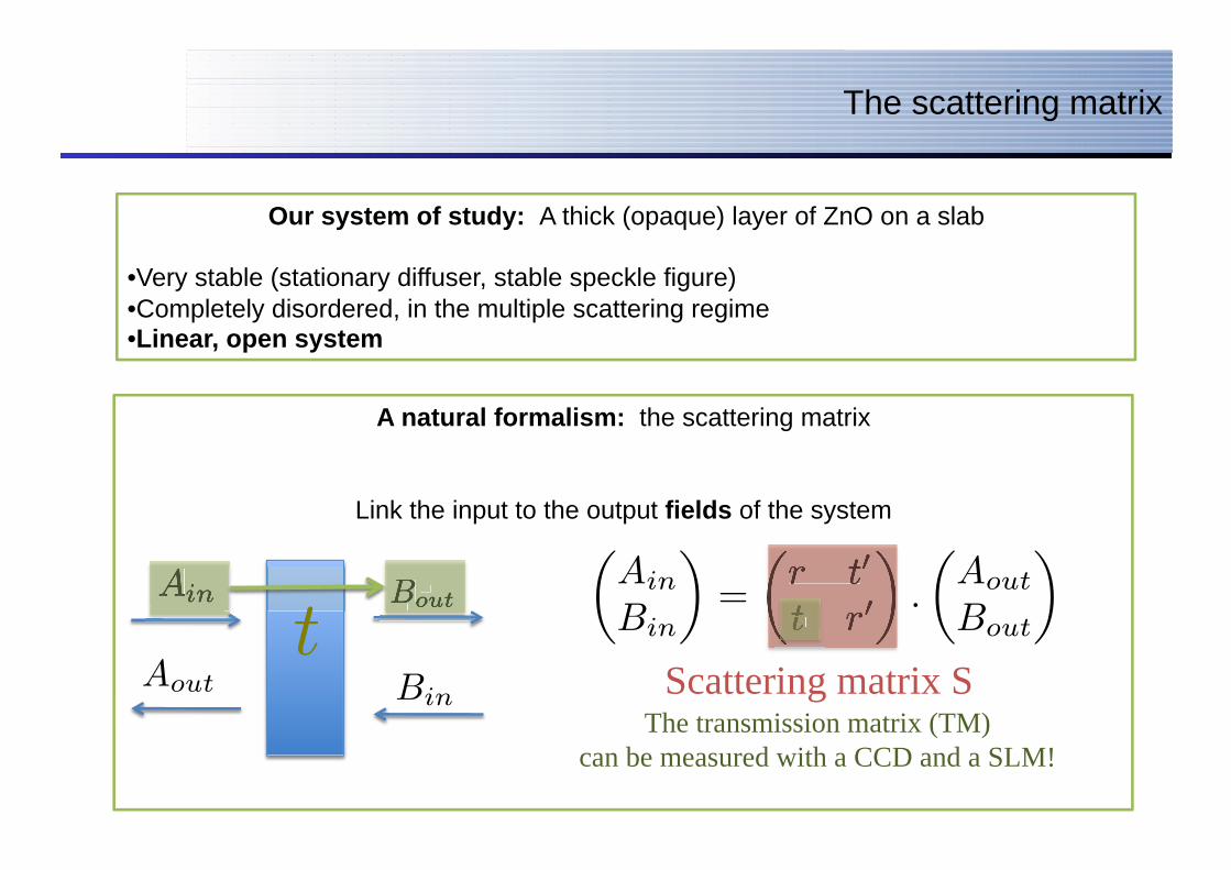
Our system of study: A thick (opaque) layer of ZnO on a slab
• Very stable (stationary diffuser, stable speckle figure) • Completely disordered, in the multiple scattering regime • Linear, open system
A natural formalism: the scattering matrix
Link the input to the output fields of the system
Ain
Aout
Bout
Bin
�Ain
Bin
�=
�r t�
t r�
�.
�Aout
Bout
���r t�
t r�
�
Scattering matrix S
Ainin BoutoutoutB
t
�
t r
�
t rt r
The transmission matrix (TM) can be measured with a CCD and a SLM!

Overview
• Experimental measurement of the Transmission Matrix (we don’t have transducers!)
• Imaging applications
• Fundamental insight on the medium
Experimental setup
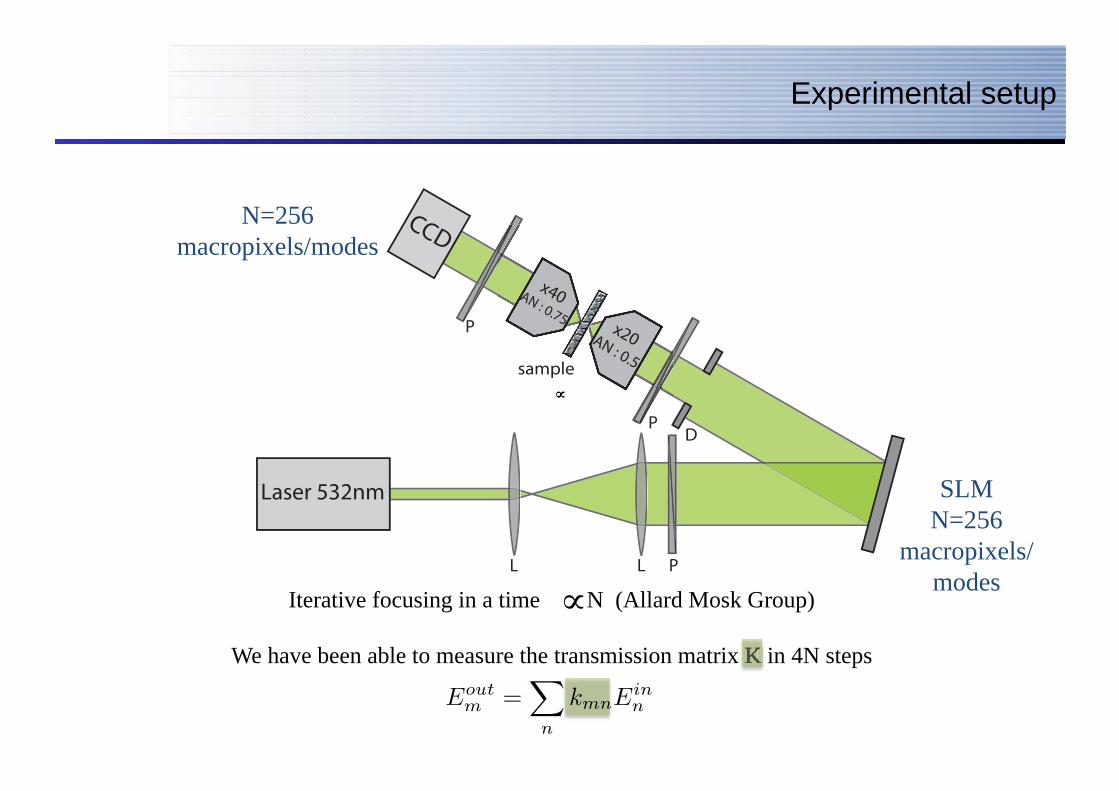
N=256 macropixels/modes
SLM N=256
macropixels/modes
€
∝
Iterative focusing in a time N (Allard Mosk Group)
We have been able to measure the transmission matrix K in 4N steps
€
∝We have been able to measure the transmission matrix K in 4N steps We have been able to measure the transmission matrix K in 4N steps We have been able to measure the transmission matrix K in 4N steps
Eoutm =
�
n
kmnEinn
∝
x40AN : 0.75P
D
sample
P
PLL
x20AN : 0.5
CCD
Laser 532nm
Speckle interferometry
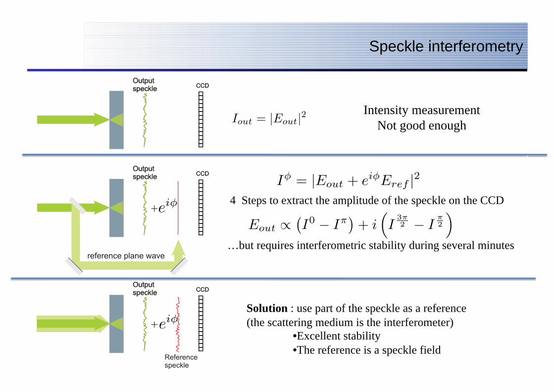
Intensity measurement Not good enough Iout = |Eout|2
eiφ
eiφ
Iφ = |Eout + eiφEref |2
Eout ∝�I0 − Iπ
�+ i
�I
3π2 − I
π2
�4 Steps to extract the amplitude of the speckle on the CCD
…but requires interferometric stability during several minutes
Solution : use part of the speckle as a reference (the scattering medium is the interferometer)
• Excellent stability • The reference is a speckle field

A good basis to start
• Need to turn « off » pixels • Bad SNR
The Hadamard basis is well adapted for TM reconstruction
with a phase-only SLM
The canonical (« pixels ») basis
= 0
= 1 , , ... •Need to Need to Need turn « off » pixels •Bad SNR
The canonical (« pixels ») basis
= 0
= 1 , , ...
• All pixels are « on » • Phase shift of 0 or π • Maximal intensity and SNR
The Hadamard basis
= 1
= -1 , , ... •All pixels are « on » •Phase shift of 0 or π•Maximal intensity and SNR
The Hadamard basis
= 1
= -1 , , ...
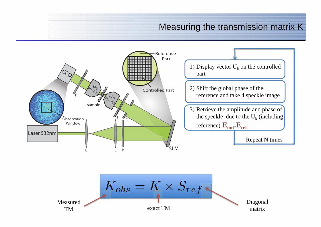
Measuring the transmission matrix K
ObservationWindow
x40AN : 0.75P
D
sample
P
PLL
x20AN : 0.5
CCD
Laser 532nm
SLM
Controlled Part
Reference Part
1) Display vector Uk on the controlled part
2) Shift the global phase of the reference and take 4 speckle image
3) Retrieve the amplitude and phase of the speckle due to the Uk (including reference) Eout.Eref
Display vector U on the controlled
Repeat N times
Kobs = K × SrefMeasured
TM exact TM Diagonal
matrix
K ref
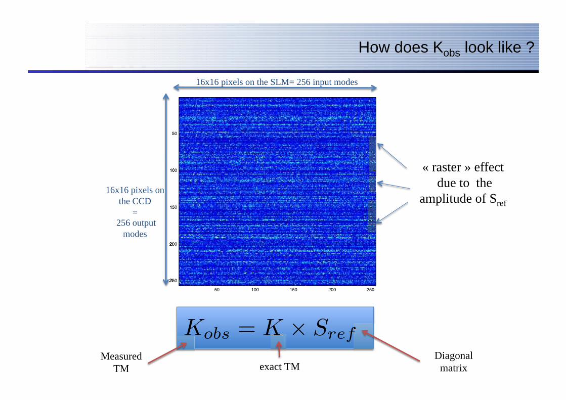
How does Kobs look like ?
Kobs = K × SrefMeasured
TM exact TM Diagonal
matrix
K ref
50 100 150 200 250
50
100
150
200
250
16x16 pixels on the SLM= 256 input modes
50
100
150
200
250
16x16 pixels on the CCD
= 256 output
modes
« raster » effect due to the
amplitude of Sref
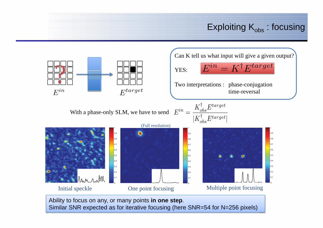
Exploiting Kobs : focusing
Can K tell us what input will give a given output?
YES:
Two interpretations : phase-conjugation time-reversal
Ein = K†Etarget
With a phase-only SLM, we have to send Ein =K†
obsEtarget
|K†obsE
target|
EtargetEin
?
Ability to focus on any, or many points in one step. Similar SNR expected as for iterative focusing (here SNR=54 for N=256 pixels)
a. b.
d.
0
0.1
0.2
0.3
0.4
0.5
0.6
0.7
0.8
0.9
1
0
0.1
0.2
0.3
0.4
0.5
0.6
0.7
0.8
0.9
1
0
0.1
0.2
0.3
0.4
0.5
0.6
0.7
0.8
0.9
1
c.0
0.1
0.2
0.3
0.4
0.5
0.6
0.7
0.8
0.9
1
a. b.
d.
0
0.1
0.2
0.3
0.4
0.5
0.6
0.7
0.8
0.9
1
0
0.1
0.2
0.3
0.4
0.5
0.6
0.7
0.8
0.9
1
0
0.1
0.2
0.3
0.4
0.5
0.6
0.7
0.8
0.9
1
c.0
0.1
0.2
0.3
0.4
0.5
0.6
0.7
0.8
0.9
1
Initial speckle One point focusing Multiple point focusing
(Full resolution)
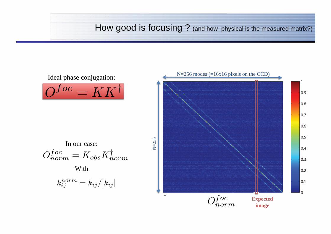
How good is focusing ? (and how physical is the measured matrix?)
Ideal phase conjugation:
In our case:
With
Ofoc = KK
†
knormij = kij/|kij |
Ofocnorm = KobsK
†norm
a. b.
d.
0
0.1
0.2
0.3
0.4
0.5
0.6
0.7
0.8
0.9
1
0
0.1
0.2
0.3
0.4
0.5
0.6
0.7
0.8
0.9
1
0
0.1
0.2
0.3
0.4
0.5
0.6
0.7
0.8
0.9
1
c.0
0.1
0.2
0.3
0.4
0.5
0.6
0.7
0.8
0.9
1
N=256 modes (=16x16 pixels on the CCD)
N=2
56
Ofocnorm
Expected image
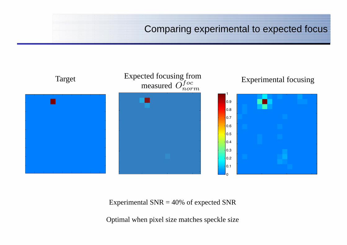
Comparing experimental to expected focus
Expected focusing from measured
Experimental focusing Target
Experimental SNR = 40% of expected SNR
Optimal when pixel size matches speckle size
Ofocnorm Experimental Last Image (Binning)
50 100 150
20
40
60
80
100
120
140
16050 100 150 200 250 300 350 400
10
20
30
40
50
60
70
80
50 100 150 200 250 300 350 400
10
20
30
40
50
60
70
80
0
0.1
0.2
0.3
0.4
0.5
0.6
0.7
0.8
0.9
1
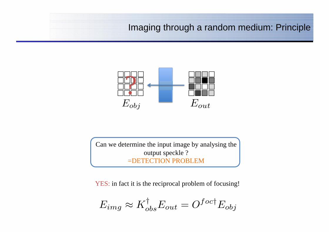
Imaging through a random medium: Principle
?
Can we determine the input image by analysing the output speckle ?
=DETECTION PROBLEM
Eobj Eout
YES: in fact it is the reciprocal problem of focusing!
Eimg ≈ K†obsEout = O
foc†Eobj = O
focEobj
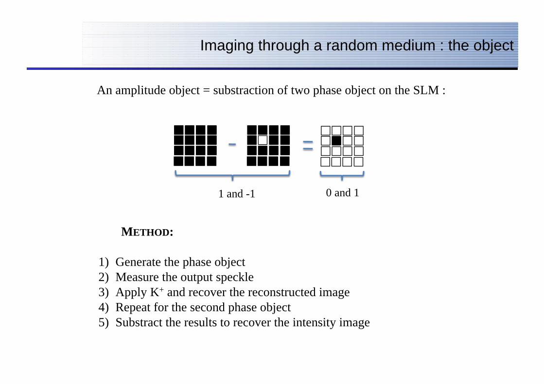
Imaging through a random medium : the object
An amplitude object = substraction of two phase object on the SLM :
1 and -1 0 and 1
METHOD:
1) Generate the phase object 2) Measure the output speckle 3) Apply K+ and recover the reconstructed image 4) Repeat for the second phase object 5) Substract the results to recover the intensity image

Imaging through a random medium : Result
a. b.
0
0.1
0.2
0.3
0.4
0.5
0.6
0.7
0.8
0.9
1
0
0.1
0.2
0.3
0.4
0.5
0.6
0.7
0.8
0.9
1
Result for one and two pixels
Same expected SNR as for focusing
Can we reconstruct a more complex image ? (we don’t know yet)
Beyond imaging : what information can we get from the TM ?
A lot ! for instance :
• Single and multiple scattering component, Backscattering cone (in reflexion) A. Aubry et al., Physical Review Letters 102, 84301 (2009).
• Field-field correlations P. Mello and A. Stone, Physical Review B 44, 3559 (1991) G. Cwilich et al., Phys. Rev. E 74, 045603(R) (2006)
• Diffusive properties, Presence of closed and open channels, Localization ?
Pendry et al., Proc. R. Soc. Lond. A (1992) 437, 67-83

The singular values
K is a NxN complex matrix, not hermitian
A singular value decomposition (SVD) consists in writing K=U Λ V , where U and V are unitary and Λ is a diagonal matrix whose nonzero elements λi are called the singular values of K.
The distribution of singular values ρ(λ) is a relevant observable of transport :
• The λi corresponds to the transmission values • The corresponding Ui and Vi corresponds to the input and output eigenvectors
• The Σλi2 corresponds to the total transmittance for a plane wave
For a multiple scattering medium, K is expected to show some universal features predicted by Random matrix theory (RMT).
A. Aubry et al., Physical Review Letters 102, 84301 (2009) Acoustics: a multiple scattering medium has been show to follow some RMT predictions. In particular ρ(λ) follow the so-called « quarter circle law ».

Extracting the singular values of K
Kobs = K × Sref
Because of Sref: Not random
(correlations)
50 100 150 200 250
50
100
150
200
250
50 100 150 200 250
50
100
150
200
250
50
100
150
200
250
300
350
400
450
Module (a.u.)
Σφ
50 100 150 200 250
50
100
150
200
250
Kfil = K × Sref
Sabs∝ K × Σφ
Compensating the amplitude of Sref, we recover K, with an unknown local
phase
SVD(Kfil)=SVD(K)
FILTERING

Experimental distribution of the singular values
0 1 2 30
0.1
0.2
0.3
0.4
0.5
0.6
The experimental distribution of SV is in good accordance with random matrix theory
Quarter circle law
Kfil
Kfil removing Neighbor
(correlations)

Conclusions
Measurement of the the transmission matrix of a multiple scattering medium.
0) not so difficult nor slow with current technology
1) An operative tool to manipulate light, A valid alternative to iterative techniques • Application to focusing • Application to detection
2) An important tool to study complex material experimentally • Demonstration of a universal behavior or RMT : the quarter circle law • fill a gap between theory and experiments
Perspectives: More applications! More fundamental measurements! Any suggestion welcome!
Arxiv:0910.5436