File_ac92fe3fca_2408_descripcion Ysimbologia Nema Din Total 2011

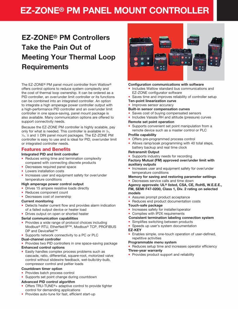
EZ-ZONE® PM Controllers Take the Pain Out of Meeting Your Thermal Loop Requirements
EZ-ZONE® PM PANEL MOUNT CONTROLLER
The EZ-ZONE® PM panel mount controller from Watlow® offers control options to reduce system complexity and the cost of thermal loop ownership. It can be ordered as a PID controller, an over/under limit controller or its functions can be combined into an integrated controller. An option to integrate a high amperage power controller output with a high-performance PID controller and an over/under limit controller in one space-saving, panel mount package is also available. Many communication options are offered to support connectivity needs.
Because the EZ-ZONE PM controller is highly scalable, pay only for what is needed. This controller is available in 1⁄32, 1⁄16, 1⁄8 and 1⁄4 DIN panel mount packages. The EZ-ZONE PM controller is easy to use and is ideal for PID, over/under limit or integrated controller needs.
Features and BenefitsIntegrated PID and limit controller• Reduces wiring time and termination complexity
compared with connecting discrete products• Decreases required panel space• Lowers installation costs• Increases user and equipment safety for over/under
temperature conditionsHigh amperage power control output• Drives 15 ampere resistive loads directly• Reduces component count• Decreases cost of ownershipCurrent monitoring • Detects heater current flow and provides alarm indication
of a failed output device or heater load• Drives output on open or shorted heaterSerial communication capabilities• Provides a wide range of protocol choices including
Modbus® RTU, EtherNet/IP™, Modbus® TCP, PROFIBUS DP and DeviceNet™
• Supports network connectivity to a PC or PLCDual-channel controller• Provides two PID controllers in one space-saving packageEnhanced control options• Easily handles complex process problems such as
cascade, ratio, differential, square-root, motorized valve control without slidewire feedback, wet-bulb/dry-bulb, compressor control and peltier loads
Countdown timer option• Provides batch process control• Supports set point change during countdownAdvanced PID control algorithm• Offers TRU-TUNE®+ adaptive control to provide tighter
control for demanding applications• Provides auto-tune for fast, efficient start-up
Configuration communications with software• Includes Watlow standard bus communications and
EZ-ZONE configurator software• Saves time and improves reliability of controller setupTen-point linearization curve• Improves sensor accuracyBuilt-in sensor compensation curves• Saves cost of buying compensated sensors• Includes Vaisala RH and altitude (pressure) curvesRemote set point operation• Supports convenient set point manipulation from a
remote device such as a master control or PLCProfile capability• Offers pre-programmed process control• Allows ramp/soak programming with 40 total steps,
battery backup and real time clockRetransmit Output• Supports industry needs for recordingFactory Mutual (FM) approved over/under limit with auxiliary outputs • Increases user and equipment safety for over/under
temperature conditionsMemory for saving and restoring parameter settings • Decreases service calls and time downAgency approvals: UL® listed, CSA, CE, RoHS, W.E.E.E., FM, SEMI F47-0200, Class 1, Div. 2 rating on selected models• Assures prompt product acceptance• Reduces end product documentation costsTouch-safe package• Increases safety for installer/operator• Complies with IP2X requirementsConsistent termination labeling connection system • Simplifies switching between products• Speeds up user’s system documentationEZ-KEY • Enables simple, one-touch operation of user-defined,
repetitive activitiesProgrammable menu system• Reduces setup time and increases operator efficiencyThree-year warranty• Provides product support and reliability
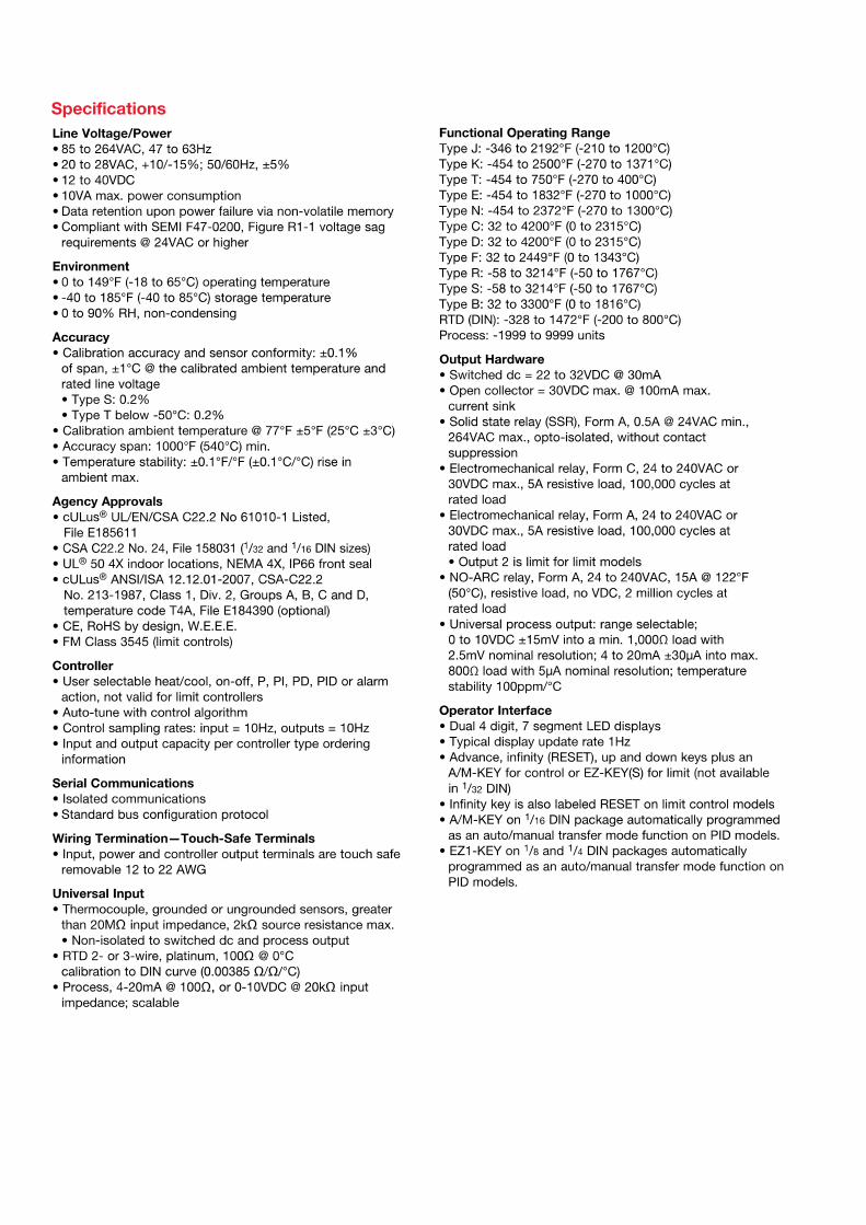
SpecificationsController• User-selectable heat/cool, on-off, P, PI, PD, PID or alarm
action, not valid for limit controllers• Auto-tune with TRU-TUNE+ adaptive control algorithm• Control sampling rates: input = 10Hz, outputs = 10HzProfile Ramp/Soak - Real Time Clock and Battery Backup• 4 profiles, 40 total steps• Accuracy (typical): ±30 PPM at 77°F (25°C)
+30/-100 PPM at -4 to 149°F (-20 to 65°C)• Battery type/typical life: lithium, three cumulative years
unpowered at 77°F (25°C)Isolated Serial Communications• EIA 232/485, Modbus® RTU• EtherNet/IP™/Modbus® TCP• DeviceNet™• PROFIBUS DPWiring Termination—Touch-Safe Terminals• Input, power and controller output terminals are touch
safe, removable, 12 to 22 AWG Universal Input• Thermocouple, grounded or ungrounded sensors greater
than 20MΩ input impedance, 3µA open sensor detection,2kΩ source resistance max.
• RTD 2- or 3-wire, platinum, 100Ω and 1000Ω @ 32°F (0°C)calibration to DIN curve (0.00385 Ω/Ω/°C)
• Process, 0-20mA @ 100Ω, or 0-10VDC @ 20kΩ, 0-50mV at20MΩ, 0-1000Ω potentionmeter; scalable; inverse scaling
Functional Operating RangeType J: -346 to 2192°F (-210 to 1200°C)Type K: -454 to 2500°F (-270 to 1371°C)Type T: -454 to 750°F (-270 to 400°C)Type E: -454 to 1832°F (-270 to 1000°C)Type N: -454 to 2372°F (-270 to 1300°C)Type C: 32 to 4200°F (0 to 2315°C)Type D: 32 to 4200°F (0 to 2315°C)Type F: 32 to 2449°F (0 to 1343°C)Type R: -58 to 3214°F (-50 to 1767°C)Type S: -58 to 3214°F (-50 to 1767°C)Type B: 32 to 3300°F (0 to 1816°C)RTD (DIN): -328 to 1472°F (-200 to 800°C)Process: -1999 to 9999 unitsAccuracy• Calibration accuracy and sensor conformity: ±0.1% of
span, ±1°C @ the calibrated ambient temperature and rated line voltage• Types R, S, B; 0.2%• Type T below -50°C; 0.2%
• Calibration ambient temperature @ 77°F ±5°F (25°C ±3°C)• Accuracy span: 1000°F (540°C) min.• Temperature stability: ±0.1°F/°F (±0.1°C/°C) rise in
ambient max.Thermistor Input• 0 to 40kΩ, 0 to 20kΩ, 0 to 10kΩ, 0 to 5kΩ• 2.252kΩ and 10kΩ base at 77°F (25°C)• Linearization curves built-inCurrent Transformer Input • Accepts 0-50mA signal (user-programmable range)• Displayed operating range and resolution can be scaled
and are user-programmableDigital Inputs (DC Voltage)• Max. input: 36V at 3mA• Logic: min. high state 3V at 0.25mA, max. low state 2VDigital Inputs (Dry Contact)• Logic: min. open resistance 10kΩ, max. closed
resistance 50Ω• Max. short circuit: 20mA
2 Digital I/O (ordered with power supply option)• Update rate: 10Hz• Input type: user-selectable, dc voltage or dry contact• Output type: switched dc• Output voltage: 24V• Output 5: 24mA max. or drive one 3-pole DIN-A-MITE®
• Output 6: 10mA max.6 Digital I/O (ordered with communications option)• Update rate: 10Hz• Input type: user-selectable, dc voltage or dry contact• Output type: user-selectable, switched dc or open collector• Switched dc output voltage: 12 to 24VDC, depending on
current draw• Switched dc max. supplied current: 40mA at 20VDC and
80mA at 12VDC• Switched dc max. low state: 2V• Open collector max. switched voltage: 32VDC• Open collector max. switched current: 1.5A per output;
8A total for all 6 outputsOutput Hardware• Switched dc: 22 to 32VDC @ 30mA max. per single output
and 40mA max. total per paired outputs (1 & 2, 3 & 4)• Open collector: 30VDC max. @ 100mA max.• SSR, Form A, 24 to 240VAC, 1A at 50°F (10°C) to 0.5A at
149°F (65°C) resistive load, 264VAC max., opto-isolated,without contact suppression, 120/240VAC @ 20VApilot duty
• Electromechanical relay, Form A, 24 to 240VAC or 30VDCmax., 5A resistive load, 100,000 cycles at rated load,120/240 @ 125VA or 24VAC @ 25VA pilot duty
• Electromechanical relay, Form C, 24 to 240VAC or 30VDCmax., 5A resistive load, 100,000 cycles at rated load,120/240 @ 125VA or 24VAC @ 25VA pilot duty
• NO-ARC relay, Form A, 85 to 264VAC, 15A @ 122°F(50°C), resistive load, no VDC, 2,000,000 cycles at ratedload
• Universal process output: range selectable; 0 to 10VDC±15mV into a min. 1,000Ω load with 2.5mV nominalresolution; 0 to 20mA ±30μA into max. 800Ω load with 5μAnominal resolution; temperature stability 100ppm/°C
Operator Interface• Dual 4-digit, 7-segment LED displays• Advance, infinity, up and down keys, plus 1 or 2
programmable EZ-KEY(s) depending on model size• Typical display update rate: 1Hz• RESET key substituted for infinity on all models with
limit controllerLine Voltage/Power• High voltage option: 85 to 264VAC, 47 to 63Hz• Low voltage option: 20 to 28VAC, +10/-15%; 50/60Hz,
±5% or 12 to 40VDC• Max. power consumption: 10VA (1⁄32 and 1⁄16 DIN);
14VA (1⁄8 and 1⁄4 DIN)• Data retention upon power failure via nonvolatile memory• Compliant with SEMI F47-0200, Figure R1-1 voltage sag
requirements @ 24VAC or higherEnvironment• Operating temperature: 0 to 149°F (-18 to 65°C)• Storage temperature: -40 to 185°F (-40 to 85°C)• Relative humidity: 0 to 90% RH, non-condensingAgency Approvals• cULus® UL/EN/CSA C22.2 No 61010-1 Listed,
File E185611• CSA C22.2 No. 24, File 158031 (1⁄32 and 1⁄16 DIN sizes)• UL® 50 4X indoor locations, NEMA 4X, UL® 50E,
Type 4X front seal• cULus® ANSI/ISA 12.12.01-2012, CSA-C22.2
No. 213-1987, Class 1, Div. 2, Groups A, B, C and D,Temperature Code T4A, File E184390 (optional)
• FM Class 3545 (limit controls)• CE, RoHS by design, W.E.E.E.• EtherNet/IP™ and DeviceNet™ ODVA Conformance
Tested
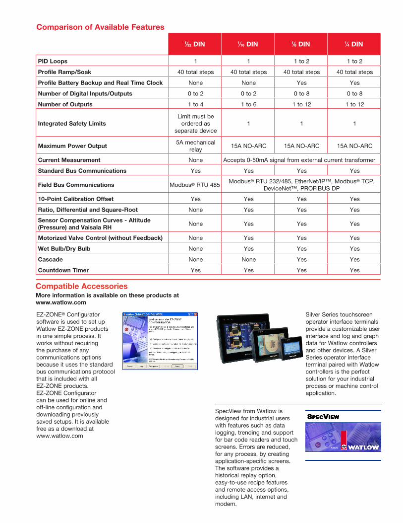
-1⁄32 DIN 1⁄16 DIN 1⁄8 DIN 1⁄4 DIN
PID Loops 1 1 1 to 2 1 to 2
Profile Ramp/Soak 40 total steps 40 total steps 40 total steps 40 total steps
Profile Battery Backup and Real Time Clock None None Yes Yes
Number of Digital Inputs/Outputs 0 to 2 0 to 2 0 to 8 0 to 8
Number of Outputs 1 to 4 1 to 6 1 to 12 1 to 12
Integrated Safety LimitsLimit must be
ordered as separate device
1 1 1
Maximum Power Output5A mechanical
relay15A NO-ARC 15A NO-ARC 15A NO-ARC
Current Measurement None Accepts 0-50mA signal from external current transformer
Standard Bus Communications Yes Yes Yes Yes
Field Bus Communications Modbus® RTU 485Modbus® RTU 232/485, EtherNet/IP™, Modbus® TCP,
DeviceNet™, PROFIBUS DP
10-Point Calibration Offset Yes Yes Yes Yes
Ratio, Differential and Square-Root None Yes Yes Yes
Sensor Compensation Curves - Altitude (Pressure) and Vaisala RH
None Yes Yes Yes
Motorized Valve Control (without Feedback) None Yes Yes Yes
Wet Bulb/Dry Bulb None Yes Yes Yes
Cascade None None Yes Yes
Countdown Timer Yes Yes Yes Yes
Comparison of Available Features
Silver Series touchscreen operator interface terminals provide a customizable user interface and log and graph data for Watlow controllers and other devices. A Silver Series operator interface terminal paired with Watlow controllers is the perfect solution for your industrial process or machine control application.
EZ-ZONE® Configurator software is used to set up Watlow EZ-ZONE products in one simple process. It works without requiring the purchase of any communications options because it uses the standard bus communications protocol that is included with all EZ-ZONE products. EZ-ZONE Configurator can be used for online and off-line configuration and downloading previously saved setups. It is available free as a download at www.watlow.com
Compatible Accessories
SpecView from Watlow is designed for industrial users with features such as data logging, trending and support for bar code readers and touch screens. Errors are reduced, for any process, by creating application-specific screens. The software provides a historical replay option, easy-to-use recipe features and remote access options, including LAN, internet and modem.
More information is available on these products at www.watlow.com
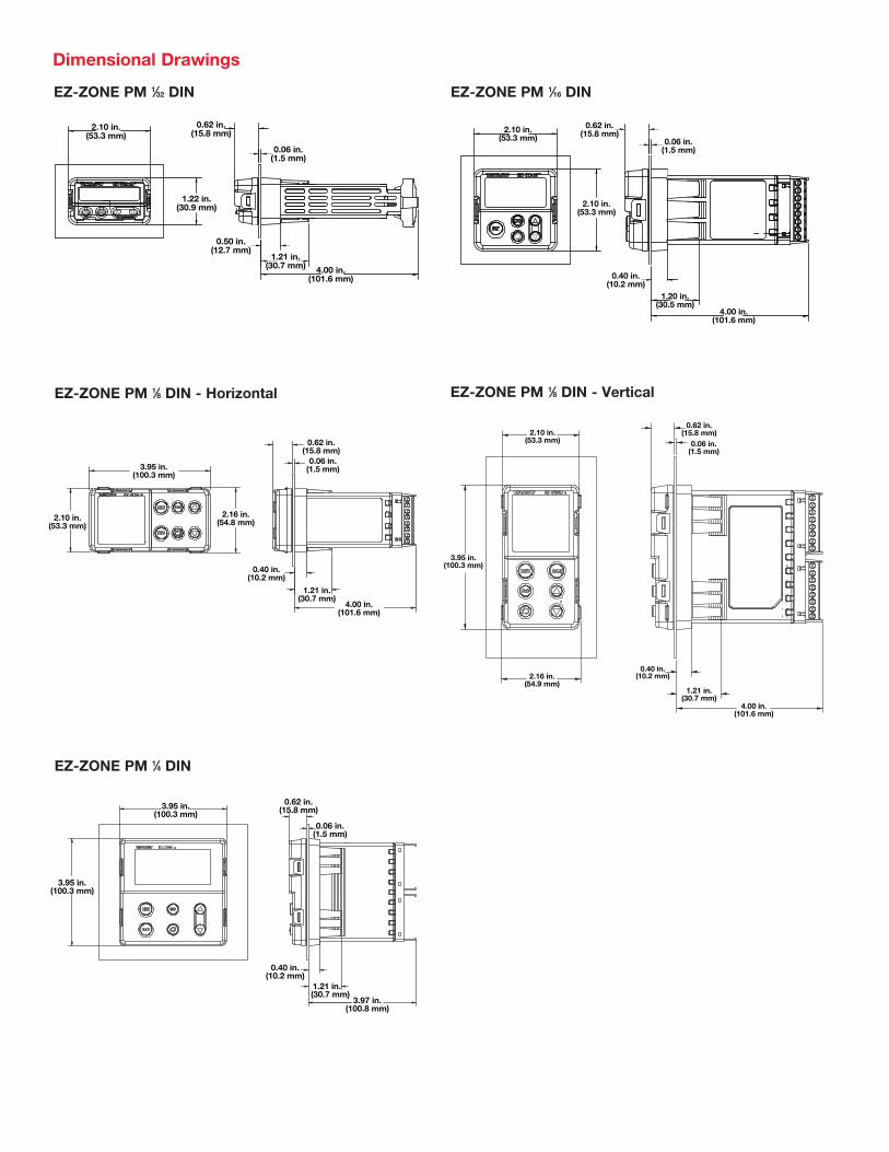
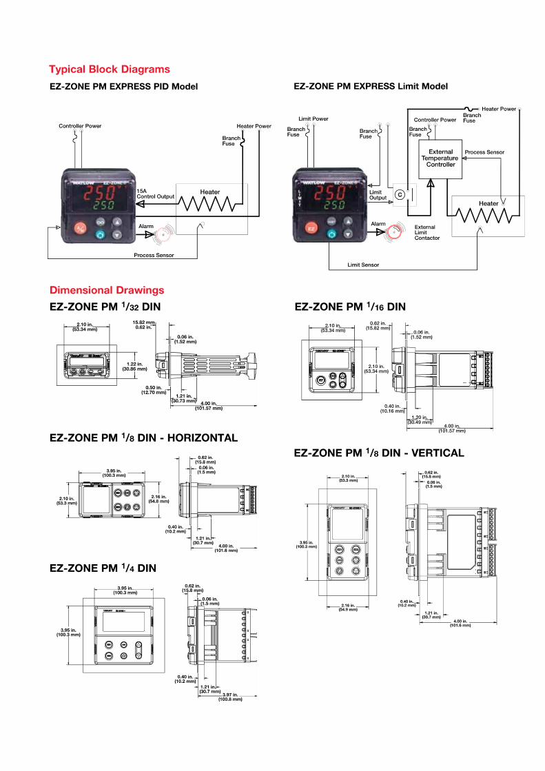
EZ-ZONE PM 1⁄8 DIN - VerticalEZ-ZONE PM 1⁄8 DIN - Horizontal
Dimensional Drawings
3.95 in.(100.3 mm)
2.10 in.(53.3 mm)
2.16 in.(54.8 mm)
0.40 in.(10.2 mm)
0.62 in.(15.8 mm)
0.06 in.(1.5 mm)
1.21 in.(30.7 mm)
4.00 in.(101.6 mm)
2.10 in.(53.3 mm)
3.95 in.(100.3 mm)
2.16 in.(54.9 mm)
0.62 in.(15.8 mm)
0.40 in.(10.2 mm)
1.21 in.(30.7 mm)
4.00 in.(101.6 mm)
0.06 in.(1.5 mm)
3.95 in.(100.3 mm)
0.62 in.(15.8 mm)
0.06 in.(1.5 mm)
0.40 in.(10.2 mm)
1.21 in. (30.7 mm)
3.97 in.(100.8 mm)
3.95 in.(100.3 mm)
EZ-ZONE PM 1⁄16 DIN
2.10 in.(53.3 mm)
0.62 in.(15.8 mm)
0.06 in.(1.5 mm)
2.10 in.(53.3 mm)
0.40 in.(10.2 mm)
4.00 in.(101.6 mm)
1.20 in.(30.5 mm)
0.62 in.(15.8 mm)
2.10 in.(53.3 mm)
1.22 in.(30.9 mm)
0.06 in.(1.5 mm)
0.50 in.(12.7 mm)
1.21 in.(30.7 mm) 4.00 in.
(101.6 mm)
EZ-ZONE PM 1⁄32 DIN
EZ-ZONE PM 1⁄4 DIN
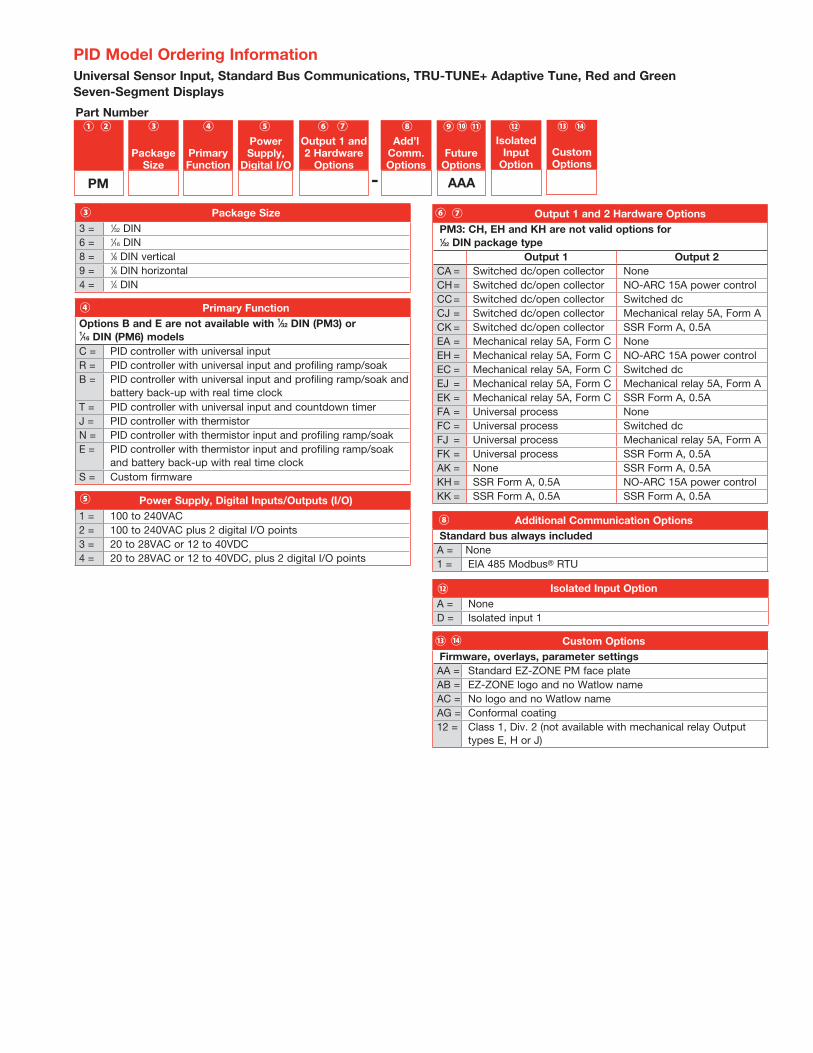
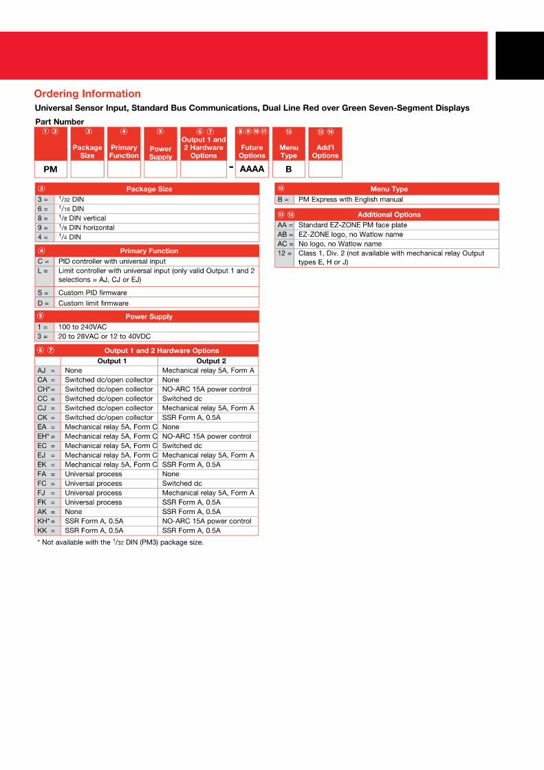
Package Size3 = 1⁄32 DIN6 = 1⁄16 DIN8 = 1⁄8 DIN vertical9 = 1⁄8 DIN horizontal4 = 1⁄4 DIN
③
Primary FunctionOptions B and E are not available with 1⁄32 DIN (PM3) or 1⁄16 DIN (PM6) modelsC = PID controller with universal inputR = PID controller with universal input and profiling ramp/soakB = PID controller with universal input and profiling ramp/soak and
battery back-up with real time clockT = PID controller with universal input and countdown timerJ = PID controller with thermistorN = PID controller with thermistor input and profiling ramp/soakE = PID controller with thermistor input and profiling ramp/soak
and battery back-up with real time clockS = Custom firmware
④
Power Supply, Digital Inputs/Outputs (I/O)1 = 100 to 240VAC2 = 100 to 240VAC plus 2 digital I/O points3 = 20 to 28VAC or 12 to 40VDC4 = 20 to 28VAC or 12 to 40VDC, plus 2 digital I/O points
⑤
Output 1 and 2 Hardware OptionsPM3: CH, EH and KH are not valid options for 1⁄32 DIN package type
Output 1 Output 2CA = Switched dc/open collector NoneCH = Switched dc/open collector NO-ARC 15A power controlCC = Switched dc/open collector Switched dcCJ = Switched dc/open collector Mechanical relay 5A, Form ACK = Switched dc/open collector SSR Form A, 0.5AEA = Mechanical relay 5A, Form C NoneEH = Mechanical relay 5A, Form C NO-ARC 15A power controlEC = Mechanical relay 5A, Form C Switched dcEJ = Mechanical relay 5A, Form C Mechanical relay 5A, Form AEK = Mechanical relay 5A, Form C SSR Form A, 0.5AFA = Universal process NoneFC = Universal process Switched dcFJ = Universal process Mechanical relay 5A, Form AFK = Universal process SSR Form A, 0.5AAK = None SSR Form A, 0.5AKH = SSR Form A, 0.5A NO-ARC 15A power controlKK = SSR Form A, 0.5A SSR Form A, 0.5A
⑥ ⑦
Additional Communication Options Standard bus always includedA = None1 = EIA 485 Modbus® RTU
⑧
Custom OptionsFirmware, overlays, parameter settingsAA = Standard EZ-ZONE PM face plateAB = EZ-ZONE logo and no Watlow nameAC = No logo and no Watlow nameAG = Conformal coating12 = Class 1, Div. 2 (not available with mechanical relay Output
types E, H or J)
⑬ ⑭
PID Model Ordering InformationUniversal Sensor Input, Standard Bus Communications, TRU-TUNE+ Adaptive Tune, Red and Green Seven-Segment Displays
AAA
Part Number
Package Size
Primary Function
Power Supply,
Digital I/O
Output 1 and 2 Hardware
Options
Add’l Comm. Options
Future Options
③ ⑤④ ⑥ ⑦ ⑧ ⑨⑩②① ⑪
PM
CustomOptions
⑬ ⑭
-
Isolated Input
Option
⑫
Isolated Input OptionA = NoneD = Isolated input 1
⑫
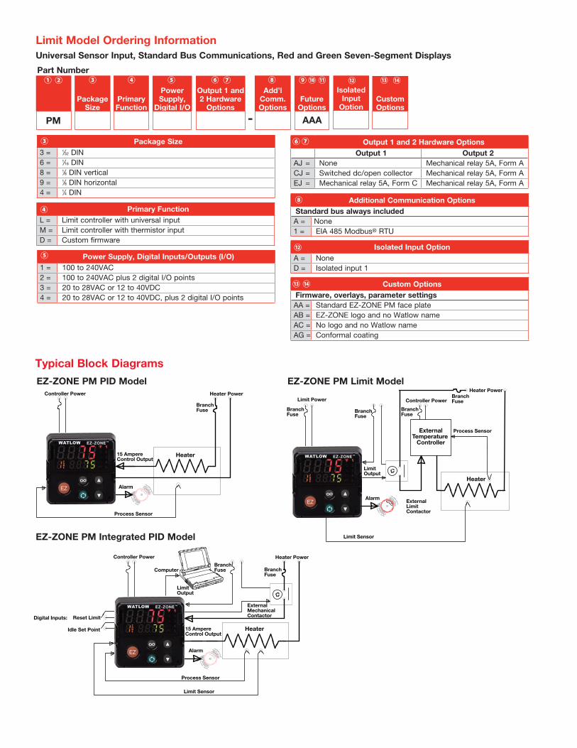
Typical Block Diagrams
BranchFuse
Heater Power
Controller Power
Process Sensor
Heater
Limit Sensor
Alarm
ExternalTemperature
Controller
Limit Power
BranchFuse
BranchFuse
LimitOutput
ExternalLimitContactor
BranchFuse
BranchFuse
Heater Power
ExternalMechanicalContactor
Limit Sensor
Process Sensor
Alarm
15 AmpereControl Output
LimitOutput
Heater
Controller Power
Computer
Digital Inputs: Reset Limit
Idle Set Point
BranchFuse
BranchFuse
Heater
Controller Power
15 AmpereControl Output
Process Sensor
Alarm
Heater Power
EZ-ZONE PM PID Model EZ-ZONE PM Limit Model
EZ-ZONE PM Integrated PID Model
Output 1 and 2 Hardware Options Output 1 Output 2
AJ = None Mechanical relay 5A, Form ACJ = Switched dc/open collector Mechanical relay 5A, Form AEJ = Mechanical relay 5A, Form C Mechanical relay 5A, Form A
⑥⑦
Limit Model Ordering Information
Package Size3 = 1⁄32 DIN6 = 1⁄16 DIN8 = 1⁄8 DIN vertical9 = 1⁄8 DIN horizontal4 = 1⁄4 DIN
③
Primary FunctionL = Limit controller with universal inputM = Limit controller with thermistor inputD = Custom firmware
④
Power Supply, Digital Inputs/Outputs (I/O)1 = 100 to 240VAC2 = 100 to 240VAC plus 2 digital I/O points3 = 20 to 28VAC or 12 to 40VDC4 = 20 to 28VAC or 12 to 40VDC, plus 2 digital I/O points
⑤
Additional Communication Options Standard bus always includedA = None1 = EIA 485 Modbus® RTU
⑧
Custom OptionsFirmware, overlays, parameter settingsAA = Standard EZ-ZONE PM face plateAB = EZ-ZONE logo and no Watlow nameAC = No logo and no Watlow nameAG = Conformal coating
⑬ ⑭
Universal Sensor Input, Standard Bus Communications, Red and Green Seven-Segment Displays
AAA
Part Number
Package Size
Primary Function
Power Supply,
Digital I/O
Output 1 and 2 Hardware
Options
Add’l Comm. Options
Future Options
③ ⑤④ ⑥ ⑦ ⑧ ⑨⑩②① ⑪
PM
CustomOptions
⑬ ⑭
-
Isolated Input
Option
⑫
Isolated Input OptionA = NoneD = Isolated input 1
⑫
Primary FunctionOptions B and E are not available with 1⁄16 DIN (PM6) models
C = PID controller with universal inputR = PID controller with universal input and profiling ramp/soakB = PID controller with universal input and profiling ramp/soak and
battery back-up with real time clock
T = PID controller with universal input and countdown timerJ = PID controller with thermistor inputN = PID controller with thermistor input and profiling ramp/soakE = PID controller with thermistor input and profiling ramp/soak
and battery back-up with real time clockS = Custom firmware
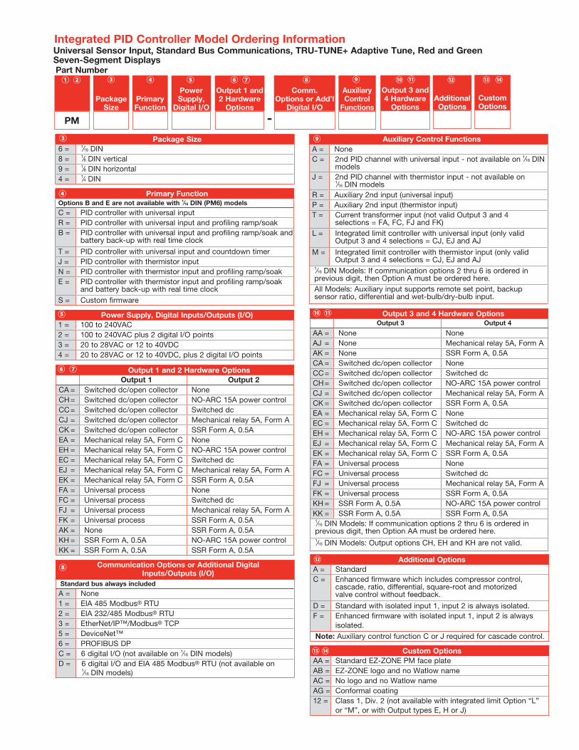
Integrated PID Controller Model Ordering Information
Package Size6 = 1⁄16 DIN8 = 1⁄8 DIN vertical9 = 1⁄8 DIN horizontal4 = 1⁄4 DIN
③
④
Power Supply, Digital Inputs/Outputs (I/O)1 = 100 to 240VAC2 = 100 to 240VAC plus 2 digital I/O points3 = 20 to 28VAC or 12 to 40VDC4 = 20 to 28VAC or 12 to 40VDC, plus 2 digital I/O points
⑤
Output 1 and 2 Hardware Options Output 1 Output 2
CA = Switched dc/open collector NoneCH = Switched dc/open collector NO-ARC 15A power controlCC = Switched dc/open collector Switched dcCJ = Switched dc/open collector Mechanical relay 5A, Form ACK = Switched dc/open collector SSR Form A, 0.5AEA = Mechanical relay 5A, Form C NoneEH = Mechanical relay 5A, Form C NO-ARC 15A power controlEC = Mechanical relay 5A, Form C Switched dcEJ = Mechanical relay 5A, Form C Mechanical relay 5A, Form AEK = Mechanical relay 5A, Form C SSR Form A, 0.5AFA = Universal process NoneFC = Universal process Switched dcFJ = Universal process Mechanical relay 5A, Form AFK = Universal process SSR Form A, 0.5AAK = None SSR Form A, 0.5AKH = SSR Form A, 0.5A NO-ARC 15A power controlKK = SSR Form A, 0.5A SSR Form A, 0.5A
⑥ ⑦
Communication Options or Additional Digital Inputs/Outputs (I/O)
Standard bus always included
A = None1 = EIA 485 Modbus® RTU2 = EIA 232/485 Modbus® RTU3 = EtherNet/IP™/Modbus® TCP5 = DeviceNet™6 = PROFIBUS DPC = 6 digital I/O (not available on 1⁄16 DIN models)D = 6 digital I/O and EIA 485 Modbus® RTU (not available on
1⁄16 DIN models)
⑧
Universal Sensor Input, Standard Bus Communications, TRU-TUNE+ Adaptive Tune, Red and Green Seven-Segment Displays
Output 3 and 4 Hardware Options Output 3 Output 4
AA = None NoneAJ = None Mechanical relay 5A, Form AAK = None SSR Form A, 0.5ACA = Switched dc/open collector NoneCC = Switched dc/open collector Switched dcCH = Switched dc/open collector NO-ARC 15A power controlCJ = Switched dc/open collector Mechanical relay 5A, Form ACK = Switched dc/open collector SSR Form A, 0.5AEA = Mechanical relay 5A, Form C NoneEC = Mechanical relay 5A, Form C Switched dcEH = Mechanical relay 5A, Form C NO-ARC 15A power controlEJ = Mechanical relay 5A, Form C Mechanical relay 5A, Form AEK = Mechanical relay 5A, Form C SSR Form A, 0.5AFA = Universal process NoneFC = Universal process Switched dcFJ = Universal process Mechanical relay 5A, Form AFK = Universal process SSR Form A, 0.5AKH = SSR Form A, 0.5A NO-ARC 15A power controlKK = SSR Form A, 0.5A SSR Form A, 0.5A1⁄16 DIN Models: If communication options 2 thru 6 is ordered in previous digit, then Option AA must be ordered here.1⁄16 DIN Models: Output options CH, EH and KH are not valid.
⑩ ⑪
Auxiliary Control FunctionsA = NoneC = 2nd PID channel with universal input - not available on 1⁄16 DIN
models
J = 2nd PID channel with thermistor input - not available on 1⁄16 DIN models
R = Auxiliary 2nd input (universal input)P = Auxiliary 2nd input (thermistor input)T = Current transformer input (not valid Output 3 and 4
selections = FA, FC, FJ and FK)L = Integrated limit controller with universal input (only valid
Output 3 and 4 selections = CJ, EJ and AJ
M = Integrated limit controller with thermistor input (only valid Output 3 and 4 selections = CJ, EJ and AJ
1⁄16 DIN Models: If communication options 2 thru 6 is ordered in previous digit, then Option A must be ordered here.All Models: Auxiliary input supports remote set point, backup sensor ratio, differential and wet-bulb/dry-bulb input.
⑨
Output 3 and 4 Hardware
OptionsAdditionalOptions
Part Number
Package Size
Primary Function
Power Supply,
Digital I/O
Output 1 and 2 Hardware
Options
Comm. Options or Add’l
Digital I/O
Auxiliary Control
Functions
③ ⑤④ ⑥ ⑦ ⑧ ⑨ ⑩②① ⑫
PM
⑪
CustomOptions
⑬ ⑭
-
Additional OptionsA = Standard C = Enhanced firmware which includes compressor control,
cascade, ratio, differential, square-root and motorized valve control without feedback.
D = Standard with isolated input 1, input 2 is always isolated.F = Enhanced firmware with isolated input 1, input 2 is always
isolated.Note: Auxiliary control function C or J required for cascade control.
⑫
Custom OptionsAA = Standard EZ-ZONE PM face plateAB = EZ-ZONE logo and no Watlow nameAC = No logo and no Watlow nameAG = Conformal coating12 = Class 1, Div. 2 (not available with integrated limit Option “L”
or “M”, or with Output types E, H or J)
⑬⑭
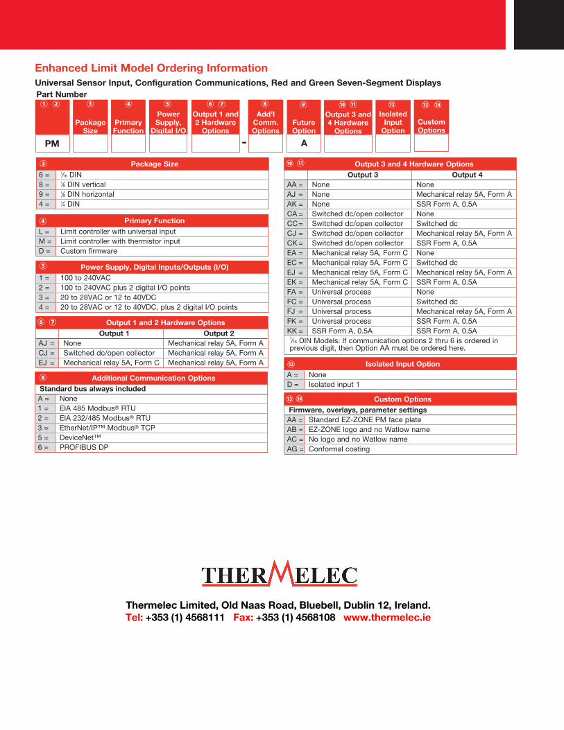
Output 1 and 2 Hardware Options Output 1 Output 2
AJ = None Mechanical relay 5A, Form ACJ = Switched dc/open collector Mechanical relay 5A, Form AEJ = Mechanical relay 5A, Form C Mechanical relay 5A, Form A
⑥ ⑦
Custom OptionsFirmware, overlays, parameter settingsAA = Standard EZ-ZONE PM face plateAB = EZ-ZONE logo and no Watlow nameAC = No logo and no Watlow nameAG = Conformal coating
⑬ ⑭
Output 3 and 4 Hardware Options Output 3 Output 4
AA = None NoneAJ = None Mechanical relay 5A, Form AAK = None SSR Form A, 0.5ACA = Switched dc/open collector NoneCC = Switched dc/open collector Switched dcCJ = Switched dc/open collector Mechanical relay 5A, Form ACK = Switched dc/open collector SSR Form A, 0.5AEA = Mechanical relay 5A, Form C NoneEC = Mechanical relay 5A, Form C Switched dcEJ = Mechanical relay 5A, Form C Mechanical relay 5A, Form AEK = Mechanical relay 5A, Form C SSR Form A, 0.5AFA = Universal process NoneFC = Universal process Switched dcFJ = Universal process Mechanical relay 5A, Form AFK = Universal process SSR Form A, 0.5AKK = SSR Form A, 0.5A SSR Form A, 0.5A
1⁄16 DIN Models: If communication options 2 thru 6 is ordered in previous digit, then Option AA must be ordered here.
⑩ ⑪
Enhanced Limit Model Ordering Information
Package Size6 = 1⁄16 DIN8 = 1⁄8 DIN vertical9 = 1⁄8 DIN horizontal4 = 1⁄4 DIN
③
Primary FunctionL = Limit controller with universal inputM = Limit controller with thermistor inputD = Custom firmware
④
Power Supply, Digital Inputs/Outputs (I/O)1 = 100 to 240VAC2 = 100 to 240VAC plus 2 digital I/O points3 = 20 to 28VAC or 12 to 40VDC4 = 20 to 28VAC or 12 to 40VDC, plus 2 digital I/O points
⑤
Additional Communication Options Standard bus always includedA = None1 = EIA 485 Modbus® RTU2 = EIA 232/485 Modbus® RTU3 = EtherNet/IP™ Modbus® TCP5 = DeviceNet™6 = PROFIBUS DP
⑧
Universal Sensor Input, Configuration Communications, Red and Green Seven-Segment Displays
A
Part Number
Package Size
Primary Function
Power Supply,
Digital I/O
Output 1 and 2 Hardware
Options
Add’l Comm. Options
Future Option
③ ⑤④ ⑥ ⑦ ⑧②①
PM
Isolated Input
OptionCustomOptions
⑬ ⑭⑫⑨Output 3 and 4 Hardware
Options
⑩ ⑪
-
Isolated Input OptionA = NoneD = Isolated input 1
⑫
Thermelec Limited, Old Naas Road, Bluebell, Dublin 12, Ireland.Tel: +353 (1) 4568111 Fax: +353 (1) 4568108 www.thermelec.ie