CONTROLLERS - Sign In 100C INSTALLATION INSTRUCTIONS EN1R-0144GE51 R1109 2 Trademark Information...
44
Copyright © 2009 Honeywell Inc. • All Rights Reserved EN1R-0144GE51 R1109 Excel 100C CONTROLLERS HONEYWELL EXCEL 5000 OPEN SYSTEM INSTALLATION INSTRUCTIONS
Transcript of CONTROLLERS - Sign In 100C INSTALLATION INSTRUCTIONS EN1R-0144GE51 R1109 2 Trademark Information...

Copyright © 2009 Honeywell Inc. • All Rights Reserved EN1R-0144GE51 R1109
Excel 100C CONTROLLERS
HONEYWELL EXCEL 5000 OPEN SYSTEM INSTALLATION INSTRUCTIONS

EXCEL 100C INSTALLATION INSTRUCTIONS
EN1R-0144GE51 R1109 2
Trademark Information Echelon, LON, LONMARK, LONWORKS, LonBuilder, NodeBuilder, LonManager, LonTalk, LonUsers, LonPoint, Neuron, 3120, 3150, the Echelon logo, the LONMARK logo, and the LonUsers logo are trademarks of Echelon Corporation registered in the United States and other countries. LonLink, LonResponse, LonSupport, and LonMaker are trademarks of Echelon Corporation.
EXCEL 100C INSTALLATION INSTRUCTIONS
3 EN1R-0144GE51 R1109
Contents
REVISION OVERVIEW.................................................................................................................................................................. 5
INTRODUCTION............................................................................................................................................................................ 6 General Safety Instructions....................................................................................... 6 Technical Requirements............................................................................................ 6 Auxiliary Devices ...................................................................................................... 6
DEVICE ASSEMBLY AND SYSTEM INSTALLATION ................................................................................................................... 7 Assembly of Controller Housing................................................................................ 7 Control Cabinet Installation....................................................................................... 8 Meaning of Control Lamp ......................................................................................... 9 Terminal Assignment Overview for Excel 100C ...................................................... 10 General Remarks about Electrical Connections ......................................................11 Cable Routing ..........................................................................................................11 Shielding of Sensor and Actuator Cables.................................................................11 Shielding of Data Transmitting Cables (System Bus and Operator Interface)......... 12 System Ground....................................................................................................... 12 RFI Suppression ..................................................................................................... 12 Cable Lengths and Cross Sectional Areas.............................................................. 13 Line Power Supply.................................................................................................. 14 Communication....................................................................................................... 14
ELECTRICAL CONNECTION...................................................................................................................................................... 16 Terminal Assignment for Digital Inputs .................................................................... 18 Terminal Assignment for Relay Modules................................................................. 19 Terminal Assignment for Relays and Actuators....................................................... 21 Connection of Alarm Relays.................................................................................... 22 Normally Open/Normally Closed Attribute............................................................... 22 System Bus (C-Bus) ............................................................................................... 23 Connections to Operating Device ........................................................................... 24
REMOTE COMMUNICATIONS.................................................................................................................................................... 30 Modem or ISDN* Terminal Adapter Connections .................................................... 31 Modem Requirements ............................................................................................ 31 No Set-Up for Standard Modem Behavior............................................................... 31 Automatic Baud Rate Synchronization.................................................................... 32 Auto / Manual Answer Detection............................................................................. 32 Resetting the Modem.............................................................................................. 32 Set-Up for Special Modem Behavior....................................................................... 32 Set-Up for In-house Telephone Systems ................................................................ 32 Set-Up for Limited Communication Speed.............................................................. 33 Troubleshooting ...................................................................................................... 33
BACKLIGHT ................................................................................................................................................................................ 33
DIMENSIONS............................................................................................................................................................................... 34

EXCEL 100C INSTALLATION INSTRUCTIONS
EN1R-0144GE51 R1109 4
U.S. SPECIFICATIONS ................................................................................................................................................................36 Electrical Connection of Sensors.............................................................................36 Transformers ...........................................................................................................38 Cables .....................................................................................................................38 Relays .....................................................................................................................39 Repeaters................................................................................................................39
EUROPEAN SPECIFICATIONS ...................................................................................................................................................40 Electrical Connection of Sensors.............................................................................40 Transformers ...........................................................................................................43 Relays .....................................................................................................................43 Cables .....................................................................................................................43 Repeaters................................................................................................................44

EXCEL 100C INSTALLATION INSTRUCTIONS
5 EN1R-0144GE51 R1109
REVISION OVERVIEW
The changes listed below show the revisions that have been made in comparison to the previous revision.
Page Changes
26 The adapter cables have been changed.
44 The ordering information for repeaters with/without housing has been changed.
NOTE: The Excel 100 has been developed to meet control requirements worldwide. Some referenced applications / accessories have been developed to meet specific regional requirements and may not be available or applicable in all locations.
EXCEL 100C INSTALLATION INSTRUCTIONS
EN1R-0144GE51 R1109 6
INTRODUCTION
General Safety Instructions
Assembly by trained personnel
CAUTION Assembly must be completed by trained personnel.
Persons who are not trained and authorized to carry out heating and electrical installation may not carry out assembly work even if this appears possible on the basis of the instructions.
Install with power off
CAUTION All assembly work must be completed with power off.
If some parts of the system are nonfunctional or have not yet been received, assembly may proceed only if power is disconnected from those assemblies. Simply switching off the unit is insufficient.
Observe regulations
IMPORTANT
The regulations VDE 0800, VDE 0100, U.S. National Electric Code NEC or others that replace them, absolutely must be observed.
Follow instructions step by step Follow instructions in accordance with the progress of the assembly step by step. Skip sections only when requested to do so in the text.
Technical Requirements
All devices ready? Assembly can start only if all system components have been installed and are ready to be operated and the control and measuring sensor cables have been connected to the control cabinet.
All cables laid? All cables must be clearly marked and laid with appropriate auxiliary accessories (cable ducts, cable ties).
Delivery complete? The delivery of all system parts must be complete.
Auxiliary Devices
Use documentation
IMPORTANT
Install all devices according to the documentation supplied with the equipment.
The instructions are designed in such a way that they provide a suggestion for all foreseeable situations. Should you be confronted with problem during assembly, please contact your appropriate dealership (see last page). If there is no one to deal with your query at that particular moment, please contact technical sales support at the factory.

EXCEL 100C INSTALLATION INSTRUCTIONS
7 EN1R-0144GE51 R1109
DEVICE ASSEMBLY AND SYSTEM INSTALLATION
Assembly of Controller Housing
1 Open cover
2 Remove tool
3 Remove screw
4 Loosen housing cover from
base
5 Loosen front right
6 Loosen rear
7 Loosen left
8 Lift housing off base
3
21
4
5 6
7 8
CB
-07
00
-Mb

EXCEL 100C INSTALLATION INSTRUCTIONS
EN1R-0144GE51 R1109 8
Control Cabinet Installation
IMPORTANT
The maximum ambient temperature for the Excel 100C depends on the mounting orientation:
Vertical mounting: max. 122°F (50°C) Horizontal mounting: max. 113°F (45°C)
1 Hang onto DIN rails
(see pages 34 and 38 for mounting dimensions)
2 Secure base
3 Cable holes
4 Snap relay modules into
place (optional) Electrical connection (see pages 10, 19 to 21)
5 Set the bus termination
switch on the back of the housing according to the system configuration (see page 14 for details).
6 Fit housing
Make sure it is straight
7 Connect operating device
(see pages 24 and up)
IMPORTANT
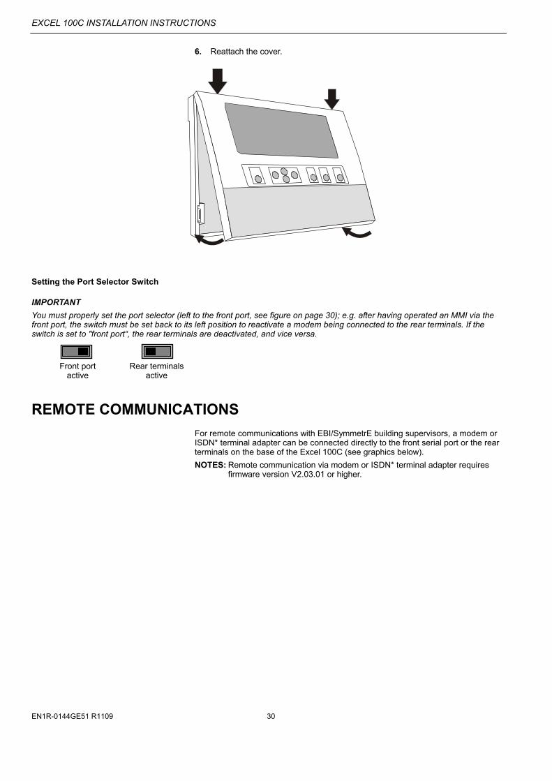
Set the port selector switch (left to the sub-D port) according to whether the front port or the rear terminals should be active (see page 30 for details).
Front port Rear terminals active active
8 Close cover
NOTE: Cover cannot be mounted with front connector plugged.
CB
-07
01
b
XD505
XD508middle
XD508beg./end

EXCEL 100C INSTALLATION INSTRUCTIONS
9 EN1R-0144GE51 R1109
Meaning of Control Lamp
Table 1. Control Lamps and their meanings
LED color status/meaning
L1 YELLOW Lit: Main voltage is present
L2 GREEN Lit: Program is running
Dark: Program is stopped
L3 RED Lit continuously: ALARM; program is stopped
L4 YELLOW Lit : Controller is transmitting via B-port
L5 YELLOW Lit: Controller is receiving via B-port
L6 YELLOW Lit: Transmission via C-bus to system bus interface
L7 YELLOW Lit: Reception via C-bus from system bus interface
L8, L9, L10, and L11 are for future use
NOTE: L4 to L11 are visible only if the cover plate has been removed.
IMPORTANT
The RESET button reboots the controller’s CPU. All plant-specific data held in the controller will be lost after a reboot. Before rebooting, it is highly recommended that you save the current application to the flash EPROM.
See section "Setting the Port Selector Switch" on page 30 for details on setting the port selector switch and serial port.
CB
-060
3-E
1
L4 L5 L6 L7RESET
BUTTON
PORTSELECTOR
SWITCH
FRONTSERIALPORT

EXCEL 100C INSTALLATION INSTRUCTIONS
EN1R-0144GE51 R1109 10
Terminal Assignment Overview for Excel 100C
1
2
3
4
5
6
7
8
9
10
11
12
13
14
15
37
38
39
40
41
42
43
44
45
46
47
48
49
50
51
52
53
54
55
56
57
58
59
60
61
62
63
64
65
66
67
68
69
70
71
72
16
17
18
19
20
21
22
23
24
25
26
27
28
29
30
31
32
33
34
35
36
AI 1 xx0101
AI 2 xx0102
AI 3 xx0103
AI 4 xx0104
AI 5 xx0105
AI 6 xx0106
AI 7 xx0107
AI 8 xx0108
AI 9 xx0201
AI 10 xx0202
AI 11 xx0203
AI 12 xx0204
DI 1 xx0301
DI 2 xx0302
DI 3 xx0303
DI 4 xx0304
DI 5 xx0305
DI 5 xx0305
shield
T x D
R x D
CTS
not used
not used
system bus
Output voltage 24 V / 300 mA isprotected against short-circuiting.After short-circuiting, it takes time(approx. 60 sec.) for voltage torecover.
reserved
common
GND
DTR
DCD
C+
C-
+5 V (Xi582), RTS (modem)
ANALOGINPUTS
ANALOGOUTPUTS
DIGITALINPUTS
DIGITALINPUTS
AO 1 xx0401
AO 2 xx0402
AO 3 xx0403
AO 4 xx0404
AO 5 xx0405
AO 6 xx0406
AO 7 xx0407
AO 8 xx0408
AO 9 xx0501
AO 10 xx0502
AO 11 xx0503
AO 12 xx0504
DI 7 xx0307
DI 8 xx0308
DI 9 xx0309
DI 10 xx0310
DI 11 xx0311
DI 12 xx0312
24V relay module(MCD3/MCE3, only!)
REF.
24 V_300 mA
-
+
24 Vac+/-20%
or21-28 Vdc
10 V10 mA
+
+alarm
(not used)
transformer
IMPORTANT
Do not connect system bus shield to earth. Use terminals 33 and 36.
NOTE: Use terminals 65 and 66 for relay modules MCD 3 or MCE 3 only. Terminals 65 and 66 provide a pulsed 24 Vdc output which is not suitable to connect direct relays. Do not use reference voltage 10 V (terminal 67, 68) to supply other devices.

EXCEL 100C INSTALLATION INSTRUCTIONS
11 EN1R-0144GE51 R1109
General Remarks about Electrical Connections
Observe all general VDE, NEC and local wiring regulations when making electrical connections.
CAUTION Electrical connection work is to be carried out by a qualified technician.
CAUTION Using free terminals as support terminals can cause system damage.
Free terminals in the base plate must not be used as wiring support points under any circumstances (danger of damage)! The electrical connection is to be made at the base plate. The appropriate connection diagrams are on pages 10 and 11. Further wiring diagrams are contained in the circuit diagrams.
IMPORTANT
Do not disconnect the Excel 100C controller from power supply for more than 72 hours.
The Excel 100C is equipped with a gold capacitor buffer that holds the RAM data and supplies the real-time clock for 72 hours in case of a power outage. Beyond this period of time, all RAM data and time information are lost.
Cable Routing
Minimum distance to mains cables:
10 mm (0.4 in.) All signal and output cables (low voltage) should be regarded as communication circuits in accordance with VDE 0100, VDE 0800 and NEC, it should therefore be routed separately from line voltage. Minimum distance 10 cm (4 in.) for unshielded cable. Minimum distance 10 mm (0.4 in.) for shielded cable. Joining sensor cables should be avoided.
Shielding of Sensor and Actuator Cables
Shielding of sensor and actuator cables with low protective voltages is not necessary if the general guidelines on cable routing are observed (see "Cable Routing" on page 11). If, under certain circumstances, the routing guidelines cannot be observed, shielded cable must always be used. IMPORTANT
Shielded cables must be grounded on one side only. The grounding of the shielded cable must be as shown in the diagram. Shielding on one sideat the control cabinet ground: Shielding of I/O cables
connected to peripherals such as sensors and actuators must be grounded at the control cabinet side, only; this to avoid ground loops.

EXCEL 100C INSTALLATION INSTRUCTIONS
EN1R-0144GE51 R1109 12
Shielding of Data Transmitting Cables (System Bus and Operator Interface)
IMPORTANT
Data transmitting cables must always be shielded to prevent radio interference.
1. System Bus Cables
Connect shield of system bus cable on both sides System bus cables must be shielded on both sides at the base plate terminal 33
and 36 of the controller device. Connection to the control cabinet ground or other ground points is not permitted (see WARNING below)! 2. Operator Interface (for external operating devices, only)
To connect remote operators units, ready-made cables are available (XW582, XW584, XW585) with the shield already connected to the computer module plug end.
For detailed information on cable types to be used in accordance with regional requirements, please refer to the U.S. and European Specifications chapters.
System Ground
WARNING
High voltage
Risk of electrical shock or equipment damage
The controller's system ground must have no connection with the control cabinet ground!
NOTE: A document providing additional information on system grounding (if demanded) is available via the Honeywell Technical Assistance Center (TAC) or, for Honeywell employees, on the Docu Server under: http://web.ge51.honeywell.de/dep/mc/TAC_Tips.
RFI Suppression
Honeywell actuators are RFI-suppressed as a standard in accordance with EN 50 081-1/EN 55 022.
CB-0236b
Primary: Secondary:
EXCEL 100C INSTALLATION INSTRUCTIONS
13 EN1R-0144GE51 R1109
Cable Lengths and Cross Sectional Areas
Cross sectional areas related to cable length
Table 2. Signal types and cross-sectional areas
cross sectional area type of signal
300 ft (100 m) 550 ft (170 m) 1300 ft (400 m)
power supply (24 Vac)
16 AWG ( 1.5 mm2)
14 AWG ( 2.5 mm2)
-
low-current signals*
20 AWG ( 0.5 mm2)
*E.g. for 0-10 V sensors, totalizers, digital inputs, 0…10 V signals for actuators.
IMPORTANT
The max. length of a signal cable with 24 Vac supply is 550 ft (170 m).
The max. length of a two-wire, 0 to 10 Vdc signal cable is 1,300 ft (400 m).
The secondary side of the transformer must not be connected to earth ground.
For detailed information on cable types to be used in accordance to regional requirements, please refer to the U.S. and European Specifications chapters.
Cabling of Actuator with 24 Vac
Supply and max. 550 ft (170 m)
TRANSFORMER
MAX. 550 ft (170 m)MIN. 14 AWG (2.5 mm )2
PRIMARYVOLTAGE
Y
GND
24 Vac
24 V
000
005
6c
Cabling of Actuator with 24 Vac Supply
from External Transformer and
max. 1,300 ft (400 m) If the distance between the controller and actuator or sensor with 24 Vac supply is greater than 550 ft (170 m), a separate external transformer for the actuator or sensor is necessary.
TRANSFORMER
EXTERNALTRANSFORMER
PRIMARYVOLTAGE
MAX. 1300 ft (400 m)
MIN.20 AWG (0.5 mm ) 2
24 Vac
230 Vac120 Vac
230 Vac120 Vac
0 TO 10 Vdc
GND
PRIMARYVOLTAGE
24 Vac
000
000
57c
NOTE: The transformer must be chosen in accordance with specifications listed in the U.S. and European Specifications chapters.

EXCEL 100C INSTALLATION INSTRUCTIONS
EN1R-0144GE51 R1109 14
IMPORTANT
We recommend installing a fuse on the secondary side of the transformer in order to protect the devices against miswiring.
Line Power Supply
The Excel 100C Controller is powered by an external transformer.
Transformer requirements for one Excel 100C Controller:
Secondary Voltage 24 Vac 20% or 21-28 Vdc
Current 1.1 A
Power 15 VA (Excel 100C, only; no MCE/MCD)
25 VA (if fully equipped with MCE/MCD)
The transformer, already installed in the cabinet, can be used to supply several con-trollers, communication devices, or peripherals (e.g. actuators, etc.) – provided it delivers sufficient power.
RIN-APU24 is supported.
For detailed information on transformers to be used in accordance to regional requirements, please refer to the U.S. and European Specifications chapters.
Standard Transformers
Requirements for standard transformers
Table 3. Requirements for standard transformers
output voltage impedance AC current
24.5 Vac to 25.5 Vac 1.15 Ω max. 2 A
24.5 Vac to 25.5 Vac 0.40 Ω max. 6 A
24.5 Vac to 25.5 Vac 0.17 Ω max. 12 A
Communication
Excel devices may communicate in different modes and lines. The principal communication scheme is shown in the accompanying figure.
Modem/ISDNCOMMUNICATION
OTHERCONTROLLERS
C-B
US
EBI/SymmetrE
EBI/SymmetrE
Excel 100C Excel 100C
Excel 500 Excel 600
Modem/ISDNExcel 100C
ModemXL-ONLINE
XI581/582(providing bus-wideaccess to all devicesconnected to C-Bus)
PRIMARY: SECONDARY:
230 Vac120 Vac
+ 20 %- 20 %
24 Vac
000
0069
a

EXCEL 100C INSTALLATION INSTRUCTIONS
15 EN1R-0144GE51 R1109
C-Bus Termination
Switch settings for C-Bus termination The back of the Excel 100C housing is equipped with a rotary switch for the C-Bus to set the bus termination appropriate for the communication speed (see Table 4 and figure below).
Table 4. Switch settings and communication speed
switch setting
communication speed
controller location compatibility
up max. 9.6 Kbaud - XD505A, XL20XD
middle max. 76.8 Kbaud middle of C-Bus XD508, XL20XD508
down max. 76.8 Kbaud beginning or end of C-Bus XD508, XL20XD508
NOTE: Modules listed in the "Compatibility" column are used in Excel 20/100B/500/600 Controllers.
Connection to modem This figure shows the connection between Excel 100C and modem via cable XW571 (see page 31 for details).
Lightning Protection
Please check with your local Honeywell representative for information on lightning protection.
Bus
Sw
_1
XD505
XD508middle
XD508beg./end
19
20
21
22
23
24
25
26
27
28
CB
-02
09
b
2
3
4
7
8
5
6
22
20
SHIELDTxD
RxD
+5 V
CTS
not used
GND
DTR
DCD
not used
YELLOW
GREEN
BLUE
VIOLET
WHITE
BLACK
BROWN

EXCEL 100C INSTALLATION INSTRUCTIONS
EN1R-0144GE51 R1109 16
ELECTRICAL CONNECTION
Terminal Assignment for Analog Inputs
Specifications
Twelve inputs (AI1 to AI12) 0 to 10 Vdc (see left drawings for impedance) 0 to 20 mA (via external 500-ohm resistor) 4 to 20 mA (via external 500-ohm resistor) NTC 20k ohms (-58°F to +302°F (-50°C to +150°C)) PT 1000 (-58°F to +302°F (-50°C to +150°C))
Protected inputs up to 40 Vdc/24 Vac 12-bit resolution 75 mV accuracy (0 to 10 V)
Accuracy of Analog Input Sensors
Table 5. Accuracy of analog input sensors in relation to temperature
measurement error / ± Kelvin (without sensor tolerance) range
Pt1000 NTC (20k ohms)
-58 to -4°F (-50 to -20°C) 1.2 K 5.0 K
-4 to 32°F (-20 to 0°C) 0.7 K 1.0 K
32 to 86°F (0 to 30°C) 0.5 K 0.3 K
86 to 158°F (30 to 70°C) 0.7 K 0.5 K
158 to 212°F (70 to 100°C) 1.2 K 1.0 K
212 to 266°F (100 to 130°C) 1.2 K 3.0 K
266 to 302°F (130 to 150°C) 1.2 K 5.5 K
For examples on electrical connection of various sensors, refer to the U.S. and European Specifications chapters.

EXCEL 100C INSTALLATION INSTRUCTIONS
17 EN1R-0144GE51 R1109
Pull-Up Resistor Handling
AD
18.2 k(pull-up)
Ω
100 kΩ
100 kΩ
5 V
AD
24.9 k(pull-up)
Ω
150 kΩ
49.9 kΩ
10 V
AD
24.9 k(pull-up)
Ω
150 kΩ
49.9 kΩ
10 V Case 1 Case 2 Case 3
Fig. 1. Input circuit diagram
Table 6. Pull-up resistor handling
pull-up load-free voltage
device voltage hardware
de-activated
by @(8
configured by DIP switch
configured by plug-in
activated for DI on AI
input circuit
diagram (Fig. 1)
with NTC or low-
impedance input
for voltage input or
high-impedance
input
XF521, XF521A
fixed NO YES case 2 8.89 V
XF526 fixed NO
NO
YES case 2 8.89 V
XFL521, XFL521A/B
10 V
YES(3 config.(6 case 1
8.89 V
Smart I/O XFC
5 V
optional switch-off
YES(4
YES
YES(7 case 3 5 V
0 V
XL20 fixed NO YES case 2 8.89 V
XL50 optional switch-off
YES(2 YES(5 case 1 0 V
XL100, XL100A
fixed
NO
YES case 2 8.89 V
XL100B
NO
YES configurable
XL100C
10 V
optional switch-off YES(1 NO
NO
YES(5 case 1
8.89 V
0 V
(1 controller firmware ≥ 2.03; (2 controller firmware ≥ 2.02; (3 controller firmware ≥ 2.03 (local/shared mode), CARE ≥ 5.00.01 (open mode); (4 CARE ≥ 5.00.01; (5 controller firmware < 2.04; (6 controller firmware < 2.04 (local/shared mode), CARE ≥ 5.01.xx (open mode); (7 CARE ≥ 5.01.xx; (8 Assigning "@" as first digit of input characteristic name (e.g.: "@0-10V") in CARE text editor disables the pull-up resistor.
EXCEL 100C INSTALLATION INSTRUCTIONS
EN1R-0144GE51 R1109 18
Terminal Assignment for Digital Inputs
DC voltage signals or AC voltage signals can be processed via the digital inputs. The Excel 100C has twelve digital inputs. From 5 V input voltage upwards, the digital signal is set to status 1. With a hysteresis of 2.5 V, the digital signal must fall below 2.5 V so that the digital status 0 is transmitted (Ri = 15 kΩ). IMPORTANT
Line voltage must not be present at any of the terminals under any circumstances. Devices with 110 V/230 Vac must be isolated by a transformer.
Six additional digital inputs are available at the terminals 49 to 54 for switching to
I, J, or K.
Table 7. Use of input terminals as counter inputs
input terminals frequency pulse duration pulse break bounce time
13 to 14 max. 15 Hz min. 20 ms min. 33 ms max. 5 ms
15 to 18, 49 to 54 max. 0.4 Hz min. 1.25 sec min. 1.25 sec max. 50 ms
EXCEL 100C INSTALLATION INSTRUCTIONS
19 EN1R-0144GE51 R1109
Terminal Assignment for Relay Modules
The relay modules facilitate the control of peripheral devices with high load via the analog outputs of the controller.
The analog outputs provide an output current of 0 to 20 mA. Via an external 500-Ω resistor, an actuator with an input impedance of 500 Ω can be used as 0 to 20 mA device.
Specifications
Twelve outputs (AO1 to AO12) 0 to 10 Vdc (+10%) output 0 to 20 mA output current (via external 500-Ω resistor, see above) 0.1 mA max. sink output current
Protected inputs up to 24 Vac 8-bit resolution 100 mV/1 LSB accuracy (1 LSB = 43 mV) 100 mV/1 LSB zero point (1 LSB = 43 mV)
The relay modules are supplied via the special relay connection of the controller (terminals 65/66) IMPORTANT
Important during connection: 1. Correct polarity 2. Under no circumstances may a relay module be connected to the reference voltage.
Several relay modules can be connected in series via the bridged terminal pair: Plus pole: Terminals 11/12 of the relay Minus pole: Terminals 13 to 16 of the relay MCD 3:
L (Fig. left) Terminal 17 controls the changeover contact K3. Terminal 18 controls the ON contacts K1, K2. Ground can be looped through terminals 2/3.

EXCEL 100C INSTALLATION INSTRUCTIONS
EN1R-0144GE51 R1109 20
MCE 3:
M (Fig. left) Terminal 16 controls the ON contact K3. Terminal 17 controls the changeover con-tact K2. Terminal 18 controls the change-over contact K1. IMPORTANT
It is not allowed to draw more than 300 mA out of terminal 65/66.
The number of MCE and MCD modules that can be used depends only on the available AOs. This means:
5 MCE 15 relays incl. watchdog alarm terminal 69 or
6 MCD 12 relays
EXCEL 100C INSTALLATION INSTRUCTIONS
21 EN1R-0144GE51 R1109
Terminal Assignment for Relays and Actuators
N Connection of external relays. Each analog output can be connected to an external relay which has similar data to the relays described under the U.S. and European Specifications chapter. The impedance of the relay must be a min. of 500 Ω for an output voltage of 11 V; an impedance of less than 500 Ω can cause erroneous output voltage. The output current is limited up to max. 20 mA.
O Type of connector for actuators with standard input signal 0 to 20 mA, but the sensor input impedance must be 500 Ω. Each channel can be used as an analog output 0 to 10 V, or, respectively, as current output 0 to 20 mA with an external 500 Ω impedance. The outputs are protected against over-voltage and overload 24 Vac.

EXCEL 100C INSTALLATION INSTRUCTIONS
EN1R-0144GE51 R1109 22
Connection of Alarm Relays
The selection of a signal transmitter for the watchdog alarm is optional. It is recommended that a switch for turning off the alarm be provided. NOTE: Terminal 69 is used to control the module MCE 3, only. The digital output cannot be used for a relay.
Normally Open/Normally Closed Attribute
Beginning with V2.04.00 firmware, the point attribute NO/NC defines the relation between the physical states (contact position and relay ON/OFF, respectively) at the digital inputs and outputs and their logical status; see also Table 8 and Table 9.
Table 8. Digital input parameters
contact position NO/NC attribute logical status input voltage
open NO 0 2.5 V
closed NO 1 5 V
open NC 1 2.5 V
closed NC 0 5 V
Table 9. Digital output parameters
relay ON/OFF NO/NC attribute logical status
ON NO 1
OFF NO 0
ON NC 0
OFF NC 1
+
55
56
57
58
59
60
61
62
63
64
65
66
67
68
69
70
71
72
COMMON
Watchdog
max. 240 V / 2 A
External supply
24V~
+
66 65
11 12 13 14 15 16 17 18
1 2 3 4 5 6 7 8
MCE 3
K 2 K3K1
CB
-07
08
-E1
not used

EXCEL 100C INSTALLATION INSTRUCTIONS
23 EN1R-0144GE51 R1109
System Bus (C-Bus)
Up to 30 controllers can communicate with one another and a PC central via the system bus. In addition to Excel 50, 100, 500/600/800 controllers, other system bus compatible components can also be connected (Excel IRC Multicontroller, Excel EMC). The system bus must be connected through the individual controllers (open ring).
Fig. 2. Open-ring connection of controllers
Excel 800 Excel 100 Excel 500 Excel 50
NOTE: Star connection is not permissible because uncontrollable line reflections may occur.
For setting up the system bus in the right way, three steps have to be followed:
cable specification for system bus
baud rate selection
The maximum communication speed of the XC5010C/XCL5010/Excel 50 / Excel 100C is 76800 baud. These controllers can be mounted together with the XC6010 or Excel 100B (with XD505A or XD508 submodule) since the XC5010C / XCL5010 / Excel 50/Excel 100C communication speed can be adjusted to match either submodule.
NOTE: When changing the baud rate of bus devices, proper communication cannot be ensured until all bus devices are set to the same baud rate again.
NOTE: When adding or removing a controller to/from the C-Bus, it may take up to two minutes to re-initialize the bus. During this time communication on the C-bus is lost.
See page 14 for details on setting the C-Bus termination on the Excel 100C.
IMPORTANT
For communication with more than 9600 baud it is required to enable the termination of the first and the last device on the C-bus (see page 14). The controllers with termination must be switched on prior to the controllers in the middle of the C-bus. The C-bus might not work if the controllers with termination are switched off.
System Bus Cable Types
The cable specification depends mainly on the baud rate. There are regional differences as to whether shielded or unshielded cable must/can be used.
For detailed information on cables to be used in accordance to regional requirements, please refer to the U.S. and European Specifications chapters.
System Bus Extension by Using Repeaters
The system bus length can be extended by using repeaters. Each repeater extends the bus length by the amount of a single bus length. Due to differences in regional guidelines, the maximum number of repeaters that may be added to a bus varies.
For detailed information on repeaters to be used in accordance to regional require-ments, please refer to the U.S. and European Specifications chapters.
EXCEL 100C INSTALLATION INSTRUCTIONS
EN1R-0144GE51 R1109 24
Connections to Operating Device
Wiring to XI582 Operator's Unit
to XL100C(front) to XI582
1
5
4
3
2
9
8 7
6
XW582
SHIELD
RxDGND
+5VETxDYELLOW
GRAY (not used)
BROWNGREENWHITE
1
4 3 2
to XL100C(rear) to XI582
XW583
SHIELD
RxDGND
+5VETxDYELLOW
GRAY (not used)
BROWNGREENWHITE
1
4 3 2
19202122
25
EXCEL 100C
XW582
XW583
XI582
XI582
The XI582 operator’s unit can be connected to either the front connector (using the XW582 cable) or the rear terminals (using the XW583 cable) of the Excel 100C. XW582 cable, length 15 ft (5 m) XW583 cable, length 15 ft (5 m)
NOTE: The controller will warm-start if the 5 V supply for the XI582 is shorted.

EXCEL 100C INSTALLATION INSTRUCTIONS
25 EN1R-0144GE51 R1109
Wiring XL-Online and Service Computer
1
5
4
3
2
9
8 7
6
to XL100C to XL-Online
1
5
4
3
2
9
8 7
6
XW585
SHIELD
RxD
GND
TxD
EXCEL 100C
XW585
PC withXL-Online
A tailor-made cable for the Excel 100C controller is available with plugs on both ends (XW585). XW585 cable, length 16 ft (5 m)
NOTE: You can also use a standard "Null modem" cable.
EXCEL 100C INSTALLATION INSTRUCTIONS
EN1R-0144GE51 R1109 26
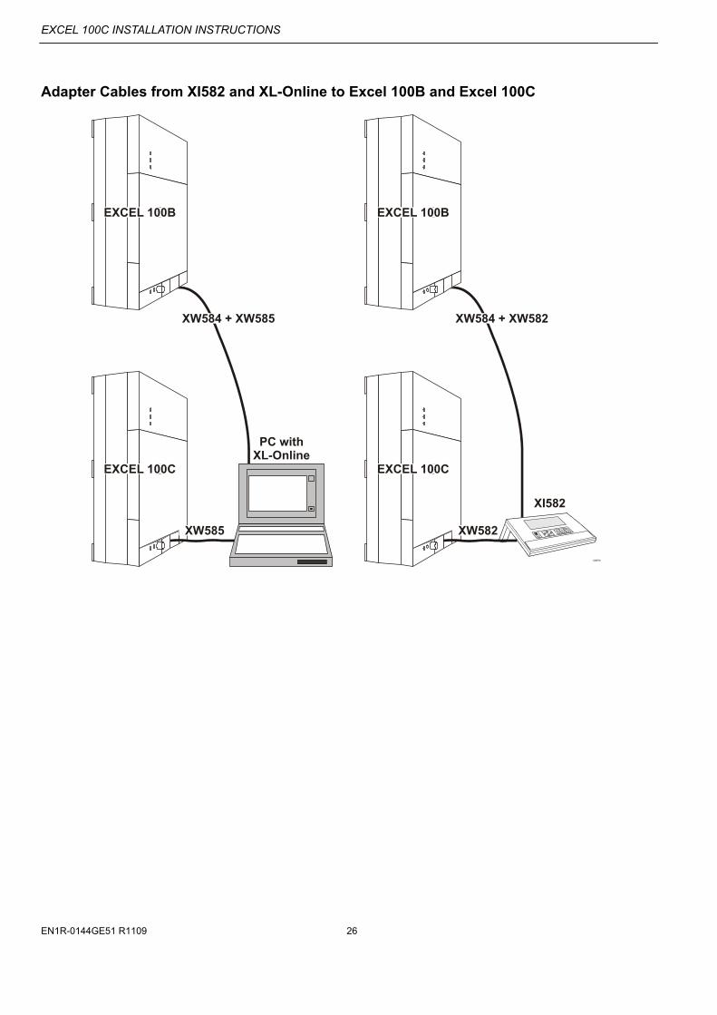
Adapter Cables from XI582 and XL-Online to Excel 100B and Excel 100C
EXCEL 100C EXCEL 100C
EXCEL 100B EXCEL 100B
XW585 XW582
XW584 + XW585 XW584 + XW582
PC withXL-Online
XI582

EXCEL 100C INSTALLATION INSTRUCTIONS
27 EN1R-0144GE51 R1109
The adapter cables are needed when the same XI582 or PC with XL-Online is used on a site where there is a mix of Excel 100C and Excel 100B controllers. Always use the following cable / combination of cables for connection:
Connecting the Excel 100B to a PC with XL-Online: use a combination of an XW584 and an XW585;
Connecting the Excel 100B to an XI582: use a combination of an XW584 and an XW582;
Connecting the Excel 100C to a PC with XL-Online: use an XW585;
Connecting the Excel 100C to an XI582: use an XW582.
12
34
5
96
78
shield
shieldshield
TxD+5VERxD
GND
greenbrownyellowwhiteTxD yellow
+5VE brownRxD greenGND white
XW 584 ....
1
3
2
4
5 6
7 8
9 10
not connected (4x)9 Code-Pin

EXCEL 100C INSTALLATION INSTRUCTIONS
EN1R-0144GE51 R1109 28
Operator's Unit XI582
1. Remove the front cover from the XI582 by inserting tip of an awl (or a similar narrow, pointed object) into the small hole on one side of the operator terminal. When the latch releases, insert the awl into the small hole on the other side of operator terminal and pry off the cover.
A
BA
B
2. Route cable from the Excel 100C.
TxD(CPU)BROWN
GREEN
WHITE
YELLOW
+VERxD(CPU)
GND
B
A

EXCEL 100C INSTALLATION INSTRUCTIONS
29 EN1R-0144GE51 R1109
3. If mounting on a wall, remove feet.
4. Attach the housing to the wall.
5. Make electrical connections (black/gray wire not used).
TxD(CPU)BROWN
GREEN
WHITE
YELLOW
+VERxD(CPU)
GND
EXCEL 100C INSTALLATION INSTRUCTIONS
EN1R-0144GE51 R1109 30
6. Reattach the cover.
Setting the Port Selector Switch
IMPORTANT
You must properly set the port selector (left to the front port, see figure on page 30); e.g. after having operated an MMI via the front port, the switch must be set back to its left position to reactivate a modem being connected to the rear terminals. If the switch is set to "front port“, the rear terminals are deactivated, and vice versa.
Front port Rear terminals active active
REMOTE COMMUNICATIONS
For remote communications with EBI/SymmetrE building supervisors, a modem or ISDN* terminal adapter can be connected directly to the front serial port or the rear terminals on the base of the Excel 100C (see graphics below).
NOTES: Remote communication via modem or ISDN* terminal adapter requires firmware version V2.03.01 or higher.
EXCEL 100C INSTALLATION INSTRUCTIONS
31 EN1R-0144GE51 R1109
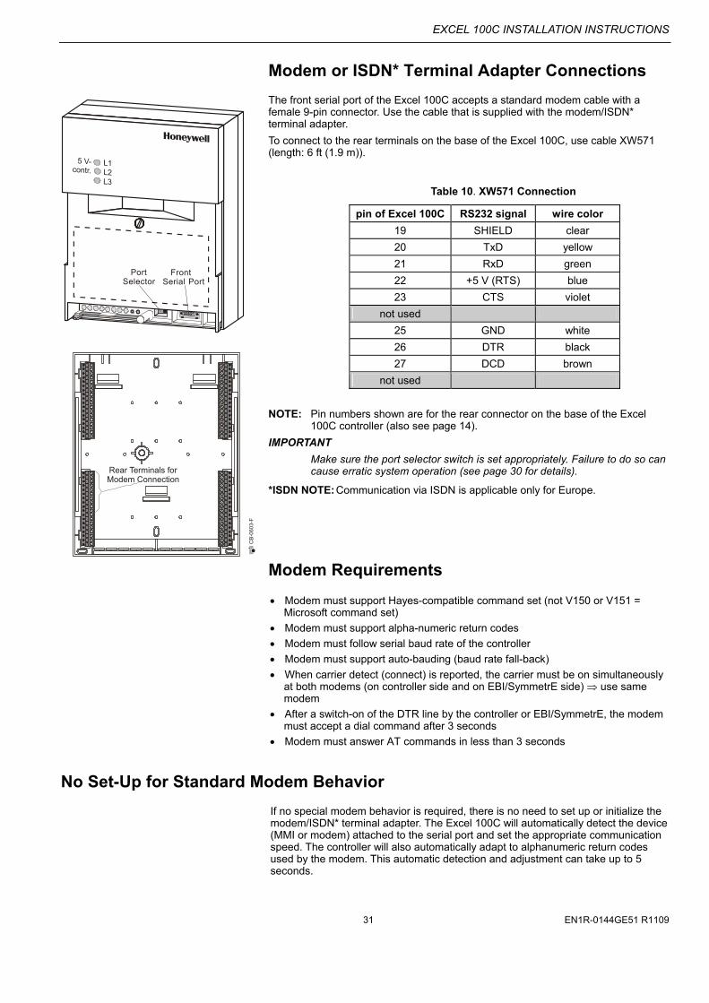
Modem or ISDN* Terminal Adapter Connections
The front serial port of the Excel 100C accepts a standard modem cable with a female 9-pin connector. Use the cable that is supplied with the modem/ISDN* terminal adapter.
To connect to the rear terminals on the base of the Excel 100C, use cable XW571 (length: 6 ft (1.9 m)).
Table 10. XW571 Connection
pin of Excel 100C RS232 signal wire color
19 SHIELD clear
20 TxD yellow
21 RxD green
22 +5 V (RTS) blue
23 CTS violet
not used
25 GND white
26 DTR black
27 DCD brown
not used
NOTE: Pin numbers shown are for the rear connector on the base of the Excel 100C controller (also see page 14).
IMPORTANT
Make sure the port selector switch is set appropriately. Failure to do so can cause erratic system operation (see page 30 for details).
*ISDN NOTE: Communication via ISDN is applicable only for Europe.
Modem Requirements
Modem must support Hayes-compatible command set (not V150 or V151 = Microsoft command set)
Modem must support alpha-numeric return codes
Modem must follow serial baud rate of the controller
Modem must support auto-bauding (baud rate fall-back)
When carrier detect (connect) is reported, the carrier must be on simultaneously at both modems (on controller side and on EBI/SymmetrE side) use same modem
After a switch-on of the DTR line by the controller or EBI/SymmetrE, the modem must accept a dial command after 3 seconds
Modem must answer AT commands in less than 3 seconds
No Set-Up for Standard Modem Behavior
If no special modem behavior is required, there is no need to set up or initialize the modem/ISDN* terminal adapter. The Excel 100C will automatically detect the device (MMI or modem) attached to the serial port and set the appropriate communication speed. The controller will also automatically adapt to alphanumeric return codes used by the modem. This automatic detection and adjustment can take up to 5 seconds.
CB
-06
03-F
FrontSerial Port
PortSelector
Rear Terminals forModem Connection

EXCEL 100C INSTALLATION INSTRUCTIONS
EN1R-0144GE51 R1109 32
NOTE: It is highly recommended that you use a state-of-the-art modem and leave it in its factory setting.
Automatic Baud Rate Synchronization
The default communication speed between the Excel 100C and the local modem/ISDN* terminal adapter is 9600 BPS.
The communication speed between the Excel 100C and EBI/SymmetrE modems/ISDN* terminal adapters is automatically synchronized by the two devices to the highest speed that both of the devices are capable of. This feature is called "autobauding" and is a feature that all state-of-the-art modems/ISDN* terminal adapters provide when left in their factory default settings.
The communication speed between the EBI/SymmetrE and its modem/ISDN* terminal adapter is part of the modem set-up at the EBI/SymmetrE.
Auto / Manual Answer Detection
The Excel 100C will automatically detect whether the modem/ISDN* terminal adapter is initialized in auto-answer or manu-answer mode, and it will set the modem to manual answer mode (S0=0)
*ISDN NOTE: Communication via ISDN is applicable only for Europe.
Resetting the Modem
For those cases where it is not clear if the modem to be used is in its factory setting, the modem can be reset to its factory setting by using the RESET MODEM command in the Start-Up sequence on the MMI. This will allow a quick and easy modem reset without having to run the modem set-up software or the Windows™ terminal program.
The RESET MODEM command causes the following commands to be sent to the modem:
1. ATZ executes hardware reset on modem
2. AT&FX3&W resets modem to factory configuration settings, configures the modem to not wait for the public phone system dial tone, and writes this to non-volatile memory.
Set-Up for Special Modem Behavior
If special modem/ISDN* terminal adapter behavior is required, the communication device should be set up according to the instructions provided with it. This typically involves running a setup program on a computer with the device connected to the computer serial port or using the Windows™ terminal program.
*ISDN NOTE: Communication via ISDN is applicable only for Europe.
Set-Up for In-house Telephone Systems
A common case of special modem behavior is when the modem is connected to an in-house telephone network requiring a prefix to be dialed before the destination number to provide access to the public telephone network. There are two important aspects of the special initialization of the modem to consider:
1. Do not wait for the public network dial tone. Typically, the init command ATX3 will trigger the modem to dial without waiting for a public network dial tone. Save this modem set-up in the modem EEPROM with the command AT&W.

EXCEL 100C INSTALLATION INSTRUCTIONS
33 EN1R-0144GE51 R1109
Check the modem handbook to verify the correct commands. Note that these commands are executed automatically with the RESET MODEM command.
2. Add the prefix required for access to the public telephone network to the destination telephone number. Depending on the in-house telephone system, a certain prefix may have to be added to the destination number in the EBI/SymmetrE system configuration/site definition screen prior to sending the set-up to the remote Excel 100C controller.
Set-Up for Limited Communication Speed
The communication speed of the modem can be fixed to a lower rate in case of data transmission errors due to telephone line limitations. See the XI581/582 Buswide Operator Interface User Guide, EN2B-126GE51, for the procedure for fixing the baud rate.
Troubleshooting
In case of any problems, the handbook of the modem or ISDN* terminal adapter must be consulted.
A “Frequently Asked Questions and Troubleshooting” document is available via the Honeywell Technical Assistance Center (TAC) or, for Honeywell employees, on the HIVE under: Technical Assistance Center/Controllers/Excel 80 and 100 and 500 and 600/ technical literature/modemfaq.doc
or on the Docu Server under: http://web.ge51.honeywell.de/dep/mc/TAC_Tips/
BACKLIGHT
Pressing any of the eight operating keys activates the backlight. If no entries are made for approximately two minutes, the backlight turns itself off automatically until a key is pressed again.

EXCEL 100C INSTALLATION INSTRUCTIONS
EN1R-0144GE51 R1109 34
DIMENSIONS
192 mm (7.56 in.)
192 mm (7.56 in.)
235
mm
(9
.25
in.)
142
mm
(5.
59 in
.)
72 mm(2.83 in.)
Excel 100C
MCD 3 - MCE 3
XI582AH
95 m
m (
3.74
in.)
42 mm(1.65 in.)
MCE 3MDE 3
48 mm(1.89 in.)93 mm (3.66 in.)
40 mm(1.57 in.)
~170 mm (6.69 in.)
~ 80
mm
(3.15 in.)
CB
-02
85
b

EXCEL 100C INSTALLATION INSTRUCTIONS
35 EN1R-0144GE51 R1109
168 mm (6.61 in.)
12 mm(0.47 in.)
8 m
m(0
.32
in.)
Base Excel 100C(shown mounted on 35 mm (1.5 in.) DIN-rails (DIN/EN 50 022 35x15)for wall mounting use screw holes located in the top center and bottom corners)
Ba
sdim
_1
Base XI582AH(wall mounting)
40
mm
(1.5
7 in
.)1
24 m
m (4
.88
in.)
216
mm
(8.5
in.)
36 m
m(1
.42
in.)
96 mm (3.78 in.)
Cable hole
190 mm (7.48 in.)
96 mm (3.78 in.)
95 mm (3.74 in.) 95 mm (3.74 in.)
24 m
m (0
.94
in.)
141
mm
(5
.55
in.)
12
mm
(0.4
7 in
.)
105
mm
(4
.13
in.)
166 mm (6.54 in.)
12 mm (0.47 in.)
12 mm(0.47 in.)

EXCEL 100C INSTALLATION INSTRUCTIONS
EN1R-0144GE51 R1109 36
U.S. SPECIFICATIONS
Electrical Connection of Sensors
Sensors and Transmitters
A Type of connection for sensors 1.) PT 1000 / I (-58°F to +302°F) (-50°C to +150°C) 2.) NTC sensors 20 kΩ Example: Room temperature sensors T7589, T7770A Discharge, Hot, or Chilled Water sensors C7031B, C, D Outside Air temperature sensor C7031F
B Type of connection for active sensors with standard output signal 0 to 10 V Example: Humidity sensor C7600B
C Type of connection for active sensors with standard output signal 0 (4) to 20 mA to be clamped down with a connector resistor R1 499 Ω / 0.25% Example: Humidity sensor C7031A, C
EXCEL 100C INSTALLATION INSTRUCTIONS
37 EN1R-0144GE51 R1109
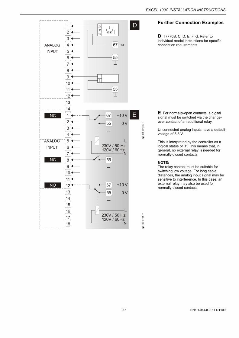
Further Connection Examples
D T7770B, C, D, E, F, G. Refer to individual model instructions for specific connection requirements
E For normally-open contacts, a digital signal must be switched via the change-over contact of an additional relay. Unconnected analog inputs have a default voltage of 8.5 V. This is interpreted by the controller as a logical status of '1'. This means that, in general, no external relay is needed for normally-closed contacts. NOTE: The relay contact must be suitable for switching low voltage. For long cable distances, the analog input signal may be sensitive to interference. In this case, an external relay may also be used for normally-closed contacts.
EXCEL 100C INSTALLATION INSTRUCTIONS
EN1R-0144GE51 R1109 38
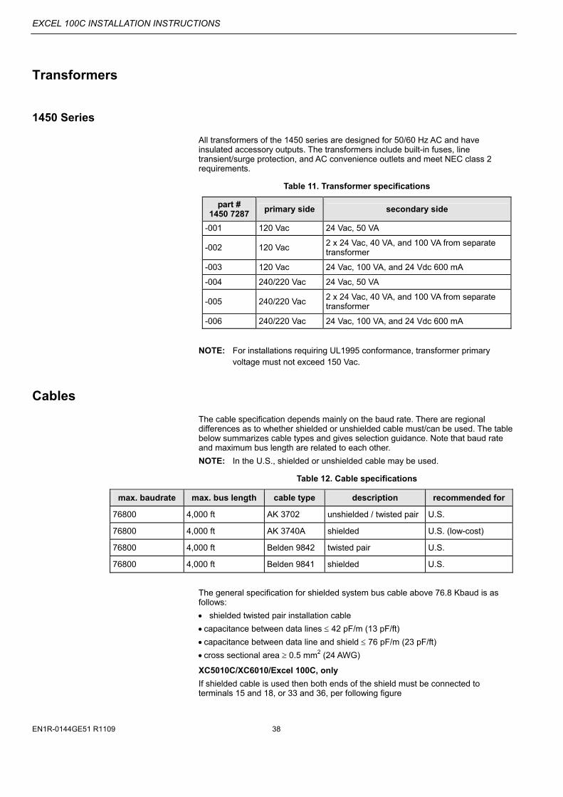
Transformers
1450 Series
All transformers of the 1450 series are designed for 50/60 Hz AC and have insulated accessory outputs. The transformers include built-in fuses, line transient/surge protection, and AC convenience outlets and meet NEC class 2 requirements.
Table 11. Transformer specifications
part # 1450 7287
primary side secondary side
-001 120 Vac 24 Vac, 50 VA
-002 120 Vac 2 x 24 Vac, 40 VA, and 100 VA from separate transformer
-003 120 Vac 24 Vac, 100 VA, and 24 Vdc 600 mA
-004 240/220 Vac 24 Vac, 50 VA
-005 240/220 Vac 2 x 24 Vac, 40 VA, and 100 VA from separate transformer
-006 240/220 Vac 24 Vac, 100 VA, and 24 Vdc 600 mA
NOTE: For installations requiring UL1995 conformance, transformer primary voltage must not exceed 150 Vac.
Cables
The cable specification depends mainly on the baud rate. There are regional differences as to whether shielded or unshielded cable must/can be used. The table below summarizes cable types and gives selection guidance. Note that baud rate and maximum bus length are related to each other.
NOTE: In the U.S., shielded or unshielded cable may be used.
Table 12. Cable specifications
max. baudrate max. bus length cable type description recommended for
76800 4,000 ft AK 3702 unshielded / twisted pair U.S.
76800 4,000 ft AK 3740A shielded U.S. (low-cost)
76800 4,000 ft Belden 9842 twisted pair U.S.
76800 4,000 ft Belden 9841 shielded U.S.
The general specification for shielded system bus cable above 76.8 Kbaud is as follows:
shielded twisted pair installation cable
capacitance between data lines 42 pF/m (13 pF/ft)
capacitance between data line and shield 76 pF/m (23 pF/ft)
cross sectional area 0.5 mm2 (24 AWG)
XC5010C/XC6010/Excel 100C, only
If shielded cable is used then both ends of the shield must be connected to terminals 15 and 18, or 33 and 36, per following figure
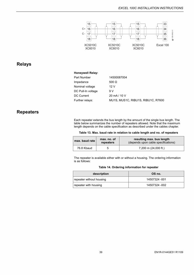
EXCEL 100C INSTALLATION INSTRUCTIONS
39 EN1R-0144GE51 R1109
CB
-04
92
-X1
15
16
17
18
15
16
17
18
15
16
17
18
33
34
35
36
XC5010CXC6010
XC5010CXC6010
XC5010CXC6010
Excel 100
Relays
Honeywell Relay:
Part Number 14500087004
Impedance 500 Ω
Nominal voltage 12 V
DC Pull-In voltage 9 V
DC Current 20 mA / 10 V
Further relays: MU1S, MUS1C, RIBU1S, RIBU1C, R7600
Repeaters
Each repeater extends the bus length by the amount of the single bus length. The table below summarizes the number of repeaters allowed. Note that the maximum length depends on the cable specification as described under the cables chapter.
Table 13. Max. baud rate in relation to cable length and no. of repeaters
max. baud rate max. no. of repeaters
resulting max. bus length (depends upon cable specifications)
76.8 Kbaud 5 7,200 m (24,000 ft.)
The repeater is available either with or without a housing. The ordering information is as follows:
Table 14. Ordering information for repeater
description OS no.
repeater without housing 14507324 -001
repeater with housing 14507324 -002

EXCEL 100C INSTALLATION INSTRUCTIONS
EN1R-0144GE51 R1109 40
EUROPEAN SPECIFICATIONS
Electrical Connection of Sensors
Sensors and Transmitters
A Type of connection for sensors 1.) PT 1000 / I (-58°F to +302°F) (-50°C to +150°C) 2.) NTC sensors 20 kΩ Example: Room temperature sensor RF 20 Inlet temperature sensor VF 20 A External temperature sensor AF20
B Type of connection for active sensors with standard output signal 0 to 10 V Example: Humidity sensor HKT 1, HRT 1
C Type of connection for active sensors with standard output signal 0 (4) to 20 mA to be clamped down with a connector resistor R1 499 Ω / 0.25% Example: Immersion temperature sensor VF 100
Air duct temperature sensor LF 100

EXCEL 100C INSTALLATION INSTRUCTIONS
41 EN1R-0144GE51 R1109
Wind sensor WS21; Sun sensor SAF25
D To measure the wind effect, wind sensor WS21 should be used.
E To measure the solar effect, the SAF 25 sun sensor should be used. In order to operate the SAF 25, the reference voltage from terminal 67 of the controller device must be connected to terminal 2 SAF 25.
EXCEL 100C INSTALLATION INSTRUCTIONS
EN1R-0144GE51 R1109 42
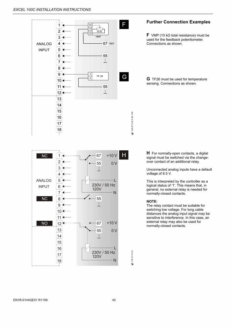
Further Connection Examples
F VMP (10 kΩ total resistance) must be used for the feedback potentiometer. Connections as shown.
G TF26 must be used for temperature sensing. Connections as shown.
H For normally-open contacts, a digital signal must be switched via the change-over contact of an additional relay. Unconnected analog inputs have a default voltage of 8.5 V. This is interpreted by the controller as a logical status of '1'. This means that, in general, no external relay is needed for normally-closed contacts. NOTE: The relay contact must be suitable for switching low voltage. For long cable distances the analog input signal may be sensitive to interference. In this case, an external relay may also be used for normally-closed contacts.
CB
-07
14
-E1
1
2
3
4
5
6
7
8
9
10
11
12
13
14
15
16
17
18
ANALOG
INPUT
H55
55
67
L
N
230V / 50 Hz120V
230V / 50 Hz120V
+10 V
0 V
55
67
L
N
+10 V
0 V
NC
NC
NO
NO
EXCEL 100C INSTALLATION INSTRUCTIONS
43 EN1R-0144GE51 R1109
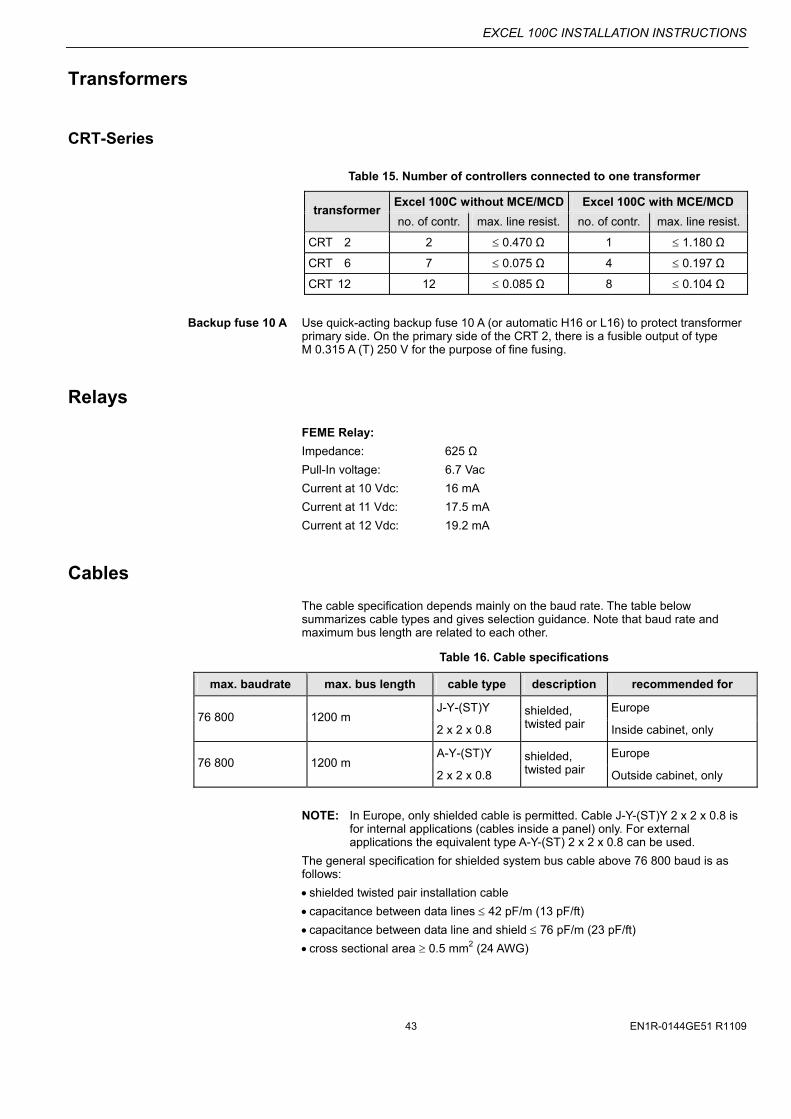
Transformers
CRT-Series
Table 15. Number of controllers connected to one transformer
Excel 100C without MCE/MCD Excel 100C with MCE/MCD transformer
no. of contr. max. line resist. no. of contr. max. line resist.
CRT 2 2 0.470 Ω 1 1.180 Ω
CRT 6 7 0.075 Ω 4 0.197 Ω
CRT 12 12 0.085 Ω 8 0.104 Ω
Backup fuse 10 A Use quick-acting backup fuse 10 A (or automatic H16 or L16) to protect transformer primary side. On the primary side of the CRT 2, there is a fusible output of type M 0.315 A (T) 250 V for the purpose of fine fusing.
Relays
FEME Relay:
Impedance: 625 Ω
Pull-In voltage: 6.7 Vac
Current at 10 Vdc: 16 mA
Current at 11 Vdc: 17.5 mA
Current at 12 Vdc: 19.2 mA
Cables
The cable specification depends mainly on the baud rate. The table below summarizes cable types and gives selection guidance. Note that baud rate and maximum bus length are related to each other.
Table 16. Cable specifications
max. baudrate max. bus length cable type description recommended for
J-Y-(ST)Y Europe 76 800 1200 m
2 x 2 x 0.8
shielded, twisted pair Inside cabinet, only
A-Y-(ST)Y Europe 76 800 1200 m
2 x 2 x 0.8
shielded, twisted pair Outside cabinet, only
NOTE: In Europe, only shielded cable is permitted. Cable J-Y-(ST)Y 2 x 2 x 0.8 is for internal applications (cables inside a panel) only. For external applications the equivalent type A-Y-(ST) 2 x 2 x 0.8 can be used.
The general specification for shielded system bus cable above 76 800 baud is as follows:
shielded twisted pair installation cable
capacitance between data lines 42 pF/m (13 pF/ft)
capacitance between data line and shield 76 pF/m (23 pF/ft)
cross sectional area 0.5 mm2 (24 AWG)

EXCEL 100C INSTALLATION INSTRUCTIONS
Manufactured for and on behalf of the Environmental and Combustion Controls Division of Honeywell Technologies Sàrl, Rolle, Z.A. La Pièce 16, Switzerland by its Authorized Representative: Automation and Control Solutions Honeywell GmbH Böblinger Strasse 17 71101 Schönaich / Germany Phone: (49) 7031 63701 Fax: (49) 7031 637493 http://ecc.emea.honeywell.com Subject to change without notice. Printed in Germany EN1R-0144GE51 R1109
XC5010C/XC6010/Excel 100C, only
If shielded cable is used then both ends of the shield must be connected to terminal 15 and 18, or 33 and 36, per following figure:
CB
-04
92
-X1
15
16
17
18
15
16
17
18
15
16
17
18
33
34
35
36
XC5010CXC6010
XC5010CXC6010
XC5010CXC6010
Excel 100
Repeaters
Each repeater extends the bus length by the amount of the single bus length. The table below summarizes the number of repeaters allowed. Note that the maximum length depends on the cable specification as described under the cables chapter.
Table 17. Max. baud rate in relation to cable length and no. of repeaters
max. baud rate max. no. of repeaters
resulting max. bus length (depends upon cable specifications)
76.8 Kbaud 5 7,200 m (24,000 ft.)
The ordering information is as follows:
Table 18. Ordering information for repeater
description OS no.
repeater panel mount (without housing) 14507324-001/U
repeater panel mount (with housing) 14507324-002/U