Control Unit - SICK
98
MMMI MMM TECHNICAL INFORMATION TECHNICAL INFORMATION SCU Control Unit Configuration, Remote Control (Modbus, OPC) Front page
Transcript of Control Unit - SICK

MMMIMMMTECHNICAL INFORMATIONTE C H N I C A L I N F O R M A T I O N
SCUControl Unit
Configuration, Remote Control (Modbus, OPC)
Front page

2 8013299/YG77/V2-3/2016-03 | SICKT E C H N I C A L I N F O R M A T I O N | SCUSubject to change without notice
ProductProduct name: SCUVersion: SCU-P100
ManufacturerSICK AGErwin-Sick-Str. 1 · 79183 Waldkirch · DeutschlandPhone: +49 7641 469-0Fax: +49 7641 469-1149E-Mail: [email protected]
Legal informationThis document is protected by copyright. All rights derived from the copyright shall be reserved for SICK AG. Reproduction of this document or parts of this document is onlypermissible within the limits of the legal determination of Copyright Law.Any modification, shortening or translation of this document is prohibited without the express written permission of SICK AG.The trademarks stated in this document are the property of their respective owner.
© SICK AG. All rights reserved.
Original documentThis document is an original document of SICK AG.

CONTENTS
1 Important information .............................................................................. 61.1 Symbols and document conventions .............................................................6
1.1.1 Warning Symbols ...........................................................................6
1.1.2 Warning Levels and Signal Words..................................................6
1.1.3 Information Symbols.......................................................................6
1.2 Responsibility of user......................................................................................6
1.2.1 Target group....................................................................................6
1.2.2 Special local conditions..................................................................6
2 Parameter................................................................................................... 72.1 SCU menu tree (overview) ..............................................................................7
2.2 Parameter........................................................................................................7
2.3 Measuring screen ...........................................................................................8
2.4 I/O ..................................................................................................................11
2.4.1 Addressing systematic..................................................................12
2.4.2 Hardware Map ..............................................................................13
2.4.2.1 CAN Bus Address 0..7 (N1..8) ..................................13
2.4.3 Data...............................................................................................14
2.4.3.1 OPC outputs...............................................................14
2.4.3.2 Modbus registers ......................................................15
2.4.3.3 Modbus I/O (up to version YBR8 [2014-12]............17
2.4.3.4 Digital inputs (DIi) .....................................................17
2.4.3.5 Digital outputs (DOi)..................................................18
2.4.3.6 Analog inputs (AIi) .....................................................18
2.4.3.7 Analog outputs (AOi) .................................................19
2.4.4 Control devices .............................................................................20
2.4.4.1 General parameters ..................................................21
ContentsContents
38013299/YG77/V2-3/2016-03 | SICK T E C H N I C A L I N F O R M A T I O N | SCUSubject to change without notice

CONTENTS
2.5 Formulas ....................................................................................................... 22
2.5.1 Introduction .................................................................................. 22
2.5.1.1 Functions of formulas............................................... 22
2.5.1.2 Application options for formulas.............................. 22
2.5.1.3 Checking a formula................................................... 22
2.5.1.4 Formula elements (overview) ................................... 22
2.5.1.5 Formula examples .................................................. 23
2.5.2 Menu functions for formulas ....................................................... 24
2.5.2.1 Formula editor .......................................................... 24
2.5.2.2 Adding a formula group ............................................ 26
2.5.2.3 Programming a formula............................................ 27
2.5.3 Variables ....................................................................................... 28
2.5.4 Activation variables ...................................................................... 28
2.5.5 Value types ................................................................................... 29
2.5.6 Tags (formula elements) .............................................................. 30
2.5.6.1 Loading tags of connected devices ......................... 30
2.5.6.2 Tags ........................................................................... 30
2.5.7 Values and states......................................................................... 32
2.5.8 Operators in formulas ................................................................. 38
2.5.9 Order of precedence for formula operators ................................ 40
2.5.10 Statements ................................................................................... 40
2.5.11 Mathematical functions in formulas .......................................... 41
2.5.12 Validation result (Drift Check)...................................................... 42
2.5.12.1 Exporting recorded data ........................................... 43
2.6 Bug(s) in formula(s) (menu) ......................................................................... 44
2.7 Status ............................................................................................................ 45
2.8 Variables and functions................................................................................ 46
2.8.1 Timer ............................................................................................. 47
2.8.1.1 Stop watches (SWi)................................................... 47
2.8.1.2 Count Downs (CDi).................................................... 47
2.8.1.3 Time functions (TFi) .................................................. 48
2.8.1.4 Cyclic trigger (CTi) ..................................................... 50
2.8.2 Limit values (LIi) ........................................................................... 51
2.8.3 Real values (RVi) .......................................................................... 51
2.8.4 Real constants (RCi)..................................................................... 52
2.8.5 Integer Values (IVi) ....................................................................... 52
2.8.6 Integer constants (ICi) .................................................................. 53
2.8.7 Boolean values (BVi) .................................................................... 53
2.8.8 Filtered values (FVi)...................................................................... 54
2.8.9 Help values (HVi) .......................................................................... 55
4 8013299/YG77/V2-3/2016-03 | SICKT E C H N I C A L I N F O R M A T I O N | SCUSubject to change without notice

CONTENTS
2.9 Sequence control programs and countdowns .............................................56
2.9.1 How sequence control programs function...................................56
2.9.1.1 Starting sequence control programs........................56
2.9.1.2 Aborting sequence control programs .......................56
2.9.1.3 Program flow .............................................................57
2.9.1.4 Variable parameters in sequence control programs ...................................................................58
2.9.2 Number .........................................................................................59
2.9.3 Sequence control programs (SCi) ................................................59
2.9.3.1 Control options ..........................................................60
2.9.3.2 Parameter transfer....................................................61
2.9.3.3 Example 1: Sequence control program....................62
2.9.3.4 Example 2: State diagram ........................................63
2.9.3.5 Sequence control program: Start .............................64
2.9.3.6 Sequence control program .......................................65
2.9.3.7 Sequence control program abort .............................65
2.9.4 Count Down (SCiCD, SCiCDj) ........................................................66
2.9.5 Manual adjustments (MAL) ..........................................................66
2.9.5.1 Transferring the parameter TGiCj to SCi ......................... 67
2.10 Test gas table (TGi) .......................................................................................68
2.11 Logbook .........................................................................................................72
2.12 Defining logbook entries...............................................................................73
2.13 Modbus..........................................................................................................75
2.14 Device ............................................................................................................76
2.15 Changing the operating state .......................................................................78
3 Remote Control ........................................................................................793.1 Modbus..........................................................................................................79
3.1.1 Function ........................................................................................79
3.1.2 Modbus specifications for the SCU..............................................79
3.1.3 Function codes..............................................................................80
3.1.4 Transmitted data ..........................................................................80
3.1.5 Addresses and data formats ........................................................80
3.1.6 Data formats .................................................................................83
3.1.7 Installation for Modbus TCP via Ethernet ....................................83
3.1.8 Installation for Modbus RTU via RS485 ......................................83
3.1.9 Setting parameters on SCU..........................................................83
3.2 OPC (option) . . . . . . . . . . . . . . . . . . . . . . . . . . . . . . . . . . . . . . . . . . . . . . . . . . . . . . . . . . . . . . . . . . . . . . . 84
3.2.1 OPC interface ................................................................................85
3.2.2 Initial start-up of SOPAS OPC server ............................................86
3.2.3 Operating the SOPAS OPC server.................................................89
3.2.4 OPC server for devices on an SCU ...............................................90
4 Glossary.....................................................................................................95
58013299/YG77/V2-3/2016-03 | SICK T E C H N I C A L I N F O R M A T I O N | SCUSubject to change without notice

1 IMPORTANT INFORMATION
1 Important information
1.1 Symbols and document conventions
1.1.1 Warning Symbols
1.1.2 Warning Levels and Signal Words
DANGER
Risk or hazardous situation which will result in severe personal injury or death.
WARNING
Risk or hazardous situation which could result in severe personal injury or death.
CAUTION
Hazard or unsafe practice which could result in less severe or minor injuries.
NOTICE
Hazard with possible risk of damage.
1.1.3 Information Symbols
1.2 Responsibility of user
1.2.1 Target group
1.2.2 Special local conditions
Follow all local laws, regulations and company-internal operating directives applicable at the respective installation location of the equipment.
Symbol Significance
Hazard (general)
Hazard by voltage
Symbol Significance
Important technical information for this product
Important information on electrical or electronic functions
NOTE:This Technical Information is aimed at qualified persons trained on the SCU and who, based on their device-specific training and knowledge of the device as well as knowledge of the relevant regulations, can assess the tasks given and recognize the dangers involved.
This Manual is only valid in combination with the ”Operating Instructions SCU”.
6 8013299/YG77/V2-3/2016-03 | SICKT E C H N I C A L I N F O R M A T I O N |SCUSubject to change without notice

PARAMETER 2
2 Parameter
2.1 SCU menu tree (overview)
2.2 Parameter
Menu: System Control Unit/Parameter
Menu tree Explanation
SCULogin → Operating Instructions SCUUpload all Parameters from Device → Operating Instructions SCUStart screen → Operating Instructions SCUMeasuring screen → Operating Instructions SCUDiagnosis → Operating Instructions SCU
Bug(s) in Formula(s) see page 44Parameter see page 7Maintenance → Operating Instructions SCU
If it is possible that parameters were changed in the SCU via the Ethernet (e.g. via SOPAS ET): ▸ Perform “Upload all Parameters from Device” (menu: System Control Unit/Upload
all Parameters from Device) before changing parameters.
Measuring screen
I/O
Formulas
Status
Variables and Functions
Sequence Controls
Test Gas Table
Logbook
Logbook texts (TXTi)
Modbus
Device
Operating States Change
/System Control Unit/Parameter/
SCUAnalyzer 1 Measure
see page 8
see page 11
see page 22
see page 45
see page 46
see page 56
see page 68
see page 72
see page 73
see page 75
see page 76
see page 78
78013299/YG77/V2-3/2016-03 | SICK T E C H N I C A L I N F O R M A T I O N |SCUSubject to change without notice

2 PARAMETER
2.3 Measuring screen
Menu: System Control Unit/Parameter/Measuring Screen
16 measured value displays can be parametrized:
Touching a Measuring screen opens a screen in which the parameters can be set for the Measuring screen.
Selecting the Measuring screens
Measuring Screen 1
Measuring Screen 2
Measuring Screen 3
etc.
/System Control Unit/Parameter/Measuring Screen/
SCUAnalyzer 1 Measure
Touch the desired Measuring screen
Measuring box is not usedLineWriter
1 measuring box4 measuring boxes
16 measuring boxes2 large, 8 small measuring boxes
6 bargraphs3 bargraphs, 2 measuring boxes3 bargraphs, 8 measuring boxes
After changes: Touch “Save”
/System Control Unit/.../Measuring Screen 1
SCUAnalyzer 1 Measure
MeasuringBox III (16)not activeLineWriterMeasuringBox I (1)MeasuringBox II (4)MeasuringBox III (16)MeasuringBox IV (2+8)BarGraph I (6)BarGraph II (3+2)BarGraph III (3+8)
Save Reset
Pop-up menu
8 8013299/YG77/V2-3/2016-03 | SICKT E C H N I C A L I N F O R M A T I O N |SCUSubject to change without notice

PARAMETER 2
● Measuring box
Example: Measuring screen 1 with measuring box III (16 measuring boxes)
● Bargraph representation
Example: Measuring screen 2 with bargraph representation I (6 bars)
To program: Touch the desired box.An input screen is displayed.
/System Control Unit/.../Measuring Screen 1
SCUAnalyzer 1
Measure
MeasuringBox III (16)
rv1 fv17
NameUnit
701
Save ResetAfter changes: Touch “Save”
Enter the desired results from “Variables and Functions”(see page 46 and / or tags see page 30).
The measuring box is then displayed as follows in theMeasuring screen:
(These texts come, for example, from the menu (e.g. RVi)or from a filter source (e,g, FVi) or from the analyzer.)
Scaling the measuring box → Operating Instructions SCU, Section “Measuring box”.
Scaling the bar → Operating Instructions SCU, Section “Bargraph representation”.
/System Control Unit/.../Measuring Screen 2
SCUAnalyzer 1
Measure
BarGraph I (6)
rv1
fv17
Name Unit
Save Reset
To program: Touch the desired bar.An input screen is displayed.
After changes: Touch “Save”
Enter the desired results from “Variables and Functions”(see page 46 and / or tags see page 30).
The bar is then displayed as follows in the Measuringscreen:
(These texts come, for example, from the menu (e.g. RVi)or from a filter source (e,g, FVi) or from the analyzer.)
98013299/YG77/V2-3/2016-03 | SICK T E C H N I C A L I N F O R M A T I O N |SCUSubject to change without notice
2 PARAMETER
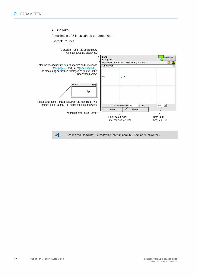
● LineWriter
A maximum of 8 lines can be parametrized.
Example: 2 lines:
/System Control Unit/.../Measuring Screen 3
SCUAnalyzer 1
Measure
LineWriter
rv1 fv17
Name
701
Save Reset
Unit
Time Scale t-axis 30 1..99 min
Time Scale t-axis: Enter the desired time
Time unit:Sec, Min, Hrs.
To program: Touch the desired box.An input screen is displayed.
After changes: Touch “Save”
Enter the desired results from “Variables and Functions”(see page 46 and / or tags see page 30).
The measuring box is then displayed as follows in theLineWriter display:
(These texts come, for example, from the menu (e.g. RVi)or from a filter source (e,g, FVi) or from the analyzer.)
Scaling the LineWriter → Operating Instructions SCU, Section “LineWriter”.
10 8013299/YG77/V2-3/2016-03 | SICKT E C H N I C A L I N F O R M A T I O N |SCUSubject to change without notice

PARAMETER 2
2.4 I/O
Menu: System Control Unit/Parameter/I/O
This menu serves to set the parameters of the data interfaces.
The SCU automatically recognizes connected I/O modules of the modular I/O system (→ Operating Instructions “Modular I/O System”).
When the SCU detects a difference to the defaults: A message is output.
You can then:
▸ Enter the appropriate configuration (see page 13).▸ When an error has occurred: Correct the error (for example: Replace the defective
module).
Hardware Map
Data
Control Devices (FDi)
/System Control Unit/Parameter/I/O/
SCUAnalyzer 1 Measure
see page 13
see page 14
see page 20
118013299/YG77/V2-3/2016-03 | SICK T E C H N I C A L I N F O R M A T I O N |SCUSubject to change without notice

2 PARAMETER
2.4.1 Addressing systematic
Representation example.
Fig. 1: Topography
All plugged in I/O modules must be reported to the SCU (see “CAN Bus Address 0..7 (N1..8)”, page 13)
12,3
CAN bus gateway 1 Node N1CAN bus address 0 [[1]] I/O module 1 (M1): AO02 I/O module 2 (M2): DI04
CAN bus gateway 2 ... 7Node N2 ... N8CAN bus address 1 ... 7 [[1]]
I/O module 1 etc.
Analyzer 1
nalyzer 2
Topography Addressing in the SCU
Node CAN busaddress[1]
I/O module Type of I/O mod-ule[2]
Topographic addressing
Functional addressing
N1 0 1 AO02 N1M1AO1(AO02)N1M1AO2(AO02)
AO1AO2
2 DI04 N1M2DI1(DI04)N1M2DI2(DI04)N1M2DI3(DI04)N1M2DI4(DI04)
DI1DI2DI3DI4
N2 1 1 AO02 N2M1AO1(AO02) A03
... ... ... ... ... ...
N8 7 ... ... ... ...
[1]Is set with the address switch on the CAN bus gateway (→ Operating Instructions “Modular I/O System”)[2]Exemplary
Abbreviation Significance
Nx Node (N) = CAN bus gateway.
Mx I/O module (M).
DIx, DOx, AIx, AOx Digital and analog inputs/outputs.
(DIxy), (DOxy), (AIxy), (AOxy), (DI04ISO), (FDxy) Type of I/O module.
12 8013299/YG77/V2-3/2016-03 | SICKT E C H N I C A L I N F O R M A T I O N |SCUSubject to change without notice

PARAMETER 2
2.4.2 Hardware Map
Menu: System Control Unit/Parameter/I/O/Hardware Map
2.4.2.1 CAN Bus Address 0..7 (N1..8)
Menu: System Control Unit/Parameter/I/O/Hardware Map/CAN Bus Address
CAN bus address switch positions 0..7 correspond to SCU addresses N1..8.
Setting of the I/O modules in the individually selected CAN bus gateway.
Example: Plugged in modules AO02, DI04, AO02 at CAN bus address 0.
CAN Bus Address 0 (N1)
CAN Bus Address 1 (N2)
CAN Bus Address 2 (N3)
etc.
/System Control Unit/Parameter/I/O/Hardware Map/
SCUAnalyzer 1 Measure
The sequence of the specified modules must agree with the sequence of the plugged in modules (beginning with the gateway).
Designation Remark
Index Consecutive module number.
Plugged-In Checkmark: Module is inserted.
As Wildcard Only for Service purposes.
Type Type of I/O module.
Activate Configuration[1] Saves changes.
[1]Appears below index 16.
▸ To take over the changed parameters: Perform “Activate Configuration”.
Save Mark Edit Copy Replace Next
/System Control Unit/.../CAN Bus Address 0 (N1)
SCUAnalyzer 1 Measure
Index Plugged-In As Wildcard Type
1 AO02
2 DI04
3 AO02
4 NULL
etc.
16 NULL
Appears below index 16Activate Configuration
138013299/YG77/V2-3/2016-03 | SICK T E C H N I C A L I N F O R M A T I O N |SCUSubject to change without notice

2 PARAMETER
2.4.3 Data
Menu: System Control Unit/Parameter/I/O/Data
2.4.3.1 OPC outputs
Menu: System Control Unit/Parameter/I/O/Data/OPC Output
This menu assigns data from the SCU to the OPC output values.
OPC Output
Modbus Output - values (MBOVi)
Modbus Output - flags (MBOFi)
Modbus Input - values (MBIVi)
Modbus Input - flags (MBIVi)
Modbus I/O (up to version YBR8 [2014-12]
Digital Input (DIi)
Digital Output (DOi)
Analog Input (AIi)
Analog Output (AOi)
/System Control Unit/Parameter/I/O/Data/
SCUAnalyzer 1 Measure
see page 14
see page 15
see page 15
see page 15
see page 15
see page 17
see page 17
see page 18
see page 18
see page 19
Designation Remark
Index Consecutive number of OPC output value.
Source Tag.
Detailed information on OPC see “OPC (option)”, page 84
Save Mark Edit Copy Replace Next
/System Control Unit/.../I/O/Data/OPC Output
SCUAnalyzer 1 Measure
Index Source
1 S2S
2 S2F0
3 S2MV1
4 LI1
5 LI2
etc.
14 8013299/YG77/V2-3/2016-03 | SICKT E C H N I C A L I N F O R M A T I O N |SCUSubject to change without notice
PARAMETER 2
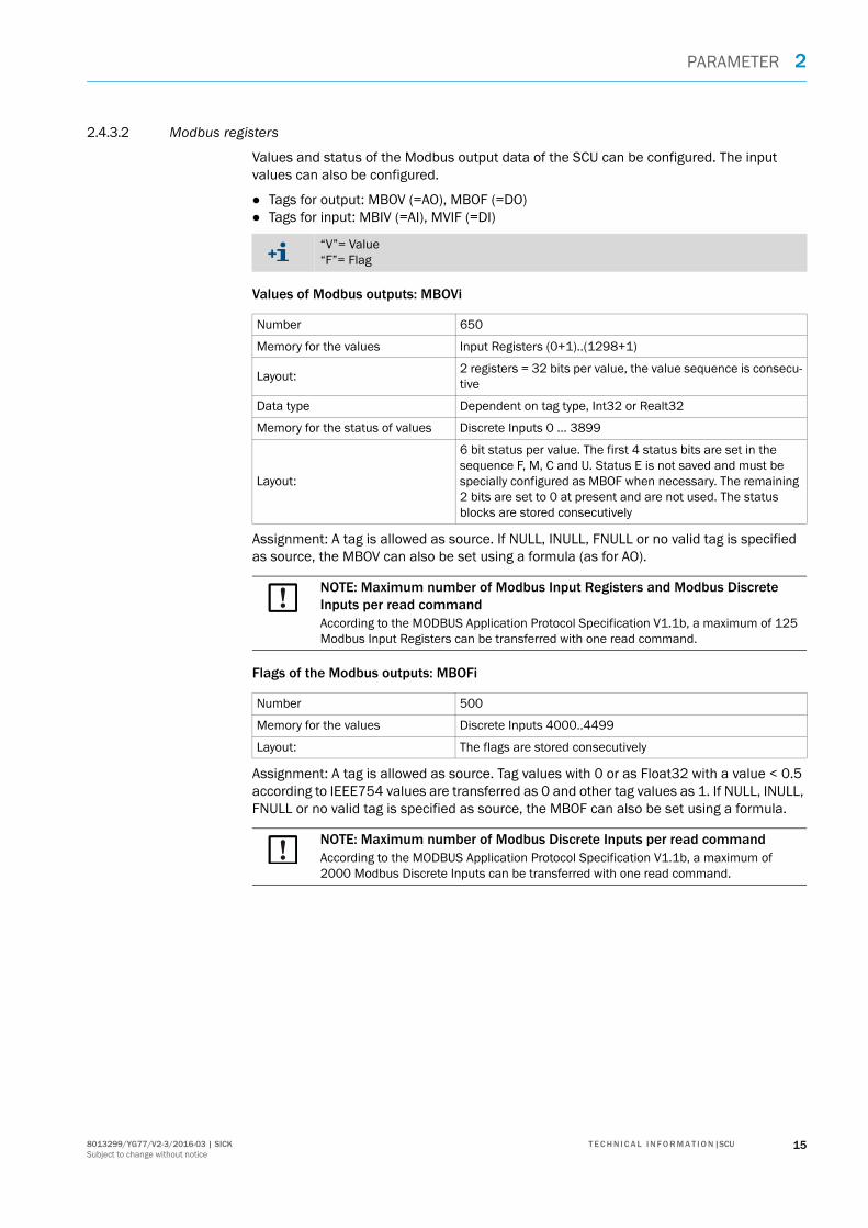
2.4.3.2 Modbus registers
Values and status of the Modbus output data of the SCU can be configured. The input values can also be configured.
● Tags for output: MBOV (=AO), MBOF (=DO)● Tags for input: MBIV (=AI), MVIF (=DI)
Values of Modbus outputs: MBOVi
Assignment: A tag is allowed as source. If NULL, INULL, FNULL or no valid tag is specified as source, the MBOV can also be set using a formula (as for AO).
Flags of the Modbus outputs: MBOFi
Assignment: A tag is allowed as source. Tag values with 0 or as Float32 with a value < 0.5 according to IEEE754 values are transferred as 0 and other tag values as 1. If NULL, INULL, FNULL or no valid tag is specified as source, the MBOF can also be set using a formula.
“V”= Value“F”= Flag
Number 650
Memory for the values Input Registers (0+1)..(1298+1)
Layout:2 registers = 32 bits per value, the value sequence is consecu-tive
Data type Dependent on tag type, Int32 or Realt32
Memory for the status of values Discrete Inputs 0 ... 3899
Layout:
6 bit status per value. The first 4 status bits are set in the sequence F, M, C and U. Status E is not saved and must be specially configured as MBOF when necessary. The remaining 2 bits are set to 0 at present and are not used. The status blocks are stored consecutively
NOTE: Maximum number of Modbus Input Registers and Modbus Discrete Inputs per read commandAccording to the MODBUS Application Protocol Specification V1.1b, a maximum of 125 Modbus Input Registers can be transferred with one read command.
Number 500
Memory for the values Discrete Inputs 4000..4499
Layout: The flags are stored consecutively
NOTE: Maximum number of Modbus Discrete Inputs per read commandAccording to the MODBUS Application Protocol Specification V1.1b, a maximum of 2000 Modbus Discrete Inputs can be transferred with one read command.
158013299/YG77/V2-3/2016-03 | SICK T E C H N I C A L I N F O R M A T I O N |SCUSubject to change without notice

2 PARAMETER
Values of the Modbus inputs: MBIVi
Interpretation: 2 registers are read pre MBIV and interpreted as Int32 or Float32 according to IEEE754 depending on the parameter setting.
Flags of the Modbus inputs: MBIFi
Diagnosis support
The Edit screens displays the parameter fields matching the configuration as well as the Modbus register type, register addresses and the current Modbus data with a short time delay. In order to simplify recognizing possible interpretation problems with the MBIVs, the 32 bit data contents are also shown in hexadecimal format at Service level.
Setting the byte sequence
The byte sequence can be set for the Modbus registers added here separately for data types Int32 and Float32 according to IEEE754 in the Modbus parameter screen. The default setting corresponds to the assignment of the registers previously used. Standard byte sequence: CD_AB.
Number 50
Memory for the values Holding Registers 2000..2099
Layout:2 registers = 32 bits per value, the value sequence is consecu-tive
NOTE: Maximum number of Modbus Holding Registers per write commandlAccording to the MODBUS Application Protocol Specification V1.1b, a maximum of 125 Modbus Holding Registers can be transferred with one write command.
Number 100
Memory for the values Coils 0..99
Layout: Flags are stored consecutively
NOTE: Maximum number of Modbus Coils per write commandAccording to the MODBUS Application Protocol Specification V1.1b, a maximum of 2000 Modbus Coils can be transferred with one write command.
NOTE:The byte sequence setting is only effective for the MBOV and MBIV introduced here. It does NOT affect the old ModBus MBO and MBI
16 8013299/YG77/V2-3/2016-03 | SICKT E C H N I C A L I N F O R M A T I O N |SCUSubject to change without notice

PARAMETER 2
2.4.3.3 Modbus I/O (up to version YBR8 [2014-12]
Menu: System Control Unit/Parameter/I/O/Data/Modbus I/O (up to version YBr8 [2014-12]
This menu assigns the data from the SCU to the Modbus input and outputs.
● Modbus outputs (MBOi)● Modbus inputs (MBIi)
Example for Modbus outputs
2.4.3.4 Digital inputs (DIi)
Menu: System Control Unit/Parameter/I/O/Data/Digital Input
This menu serves to set the parameters of the digital inputs.
Designation Remark
Index Consecutive number of Modbus output value.
Source Tag.
Detailed information on Modbus see “Modbus”, page 79
Save Mark Edit Copy Replace Next
/System Control Unit/.../I/O/Data/Modbus Output
SCUAnalyzer 1 Measure
Index Source
1 S2S
2 S2F0
3 S2MV1
4 LI1
5 LI2
etc.
Designation Remark
Index Consecutive number of the digital input (DI1, DI2, ....).
Module Topographic addressing (see page 7). Is automatically generated.
Name Freely selectable.
Inverted Checkmark: Read in inverted.
Save Mark Edit Copy Replace Next
/System Control Unit/.../I/O/Data/Digital Input (DIi)
SCUAnalyzer 1 Measure
Index Module Name Inverted
1 N1M01DI01(DI04) di1:Switch Main/Meas
2 N1M01DI02(DI04) DI2 3 N1M01DI03(DI04) DI3 etc.
178013299/YG77/V2-3/2016-03 | SICK T E C H N I C A L I N F O R M A T I O N |SCUSubject to change without notice

2 PARAMETER
2.4.3.5 Digital outputs (DOi)
Menu: System Control Unit/Parameter/I/O/Data/Digital Output
This menu serves to set the parameters of the digital outputs.
2.4.3.6 Analog inputs (AIi)
Menu: System Control Unit/Parameter/I/O/Data/Analog Input
This menu serves to set the parameters of the analog inputs.
Designation Remark
Index Consecutive number of the digital output (DO1, DO2, ....).
Module Topographic addressing (see page 7). Is automatically generated.
Source Tag.
Inverted Checkmark: Output inverted.
Save Mark Edit Copy Replace Next
/System Control Unit/.../I/O/Data/Digital Output (DOi)
SCUAnalyzer 1 Measure
Index Module Source Inverted
1 N1M02DO01(DO04) bv11
2 N1M02DO02(DO04) bv12 3 N1M02DO03(DO04) s2e9 etc.
Designation Remark
Index Consecutive number of the analog input (AI1, AI2, ....).
Module Topographic addressing (see page 7). Is automatically generated.
Name Freely selectable.
Unit Unit of read-in variable.
Gas Condition Freely selectable. Example: Dry, standard state, operational state.
Zero Select in input screen.
Range Start Scaled analog inputs.
Range End Scaled analog inputs.
Save Mark Edit Copy Replace Next
/System Control Unit/.../I/O/Data/Analog Input (AIi)
SCUAnalyzer 1 Measure
Index Module Name Unit Gas Condition Zero Range Start Range End
1 N1M14AI01(AI02) AI1 4mA ---- 4mA 0.0E00 1.0E02
2 N1M14AI02(AI02) AI2 4mA ---- 4mA 0.0E00 1.0E02
3 N1M14AI03(AI02) ai3 4mA ---- 4mA 0.0E00 1.0E02
etc.
18 8013299/YG77/V2-3/2016-03 | SICKT E C H N I C A L I N F O R M A T I O N |SCUSubject to change without notice

PARAMETER 2
2.4.3.7 Analog outputs (AOi)
Menu: System Control Unit/Parameter/I/O/Data/Analog Output
This menu serves to set the parameters of the analog outputs.
Designation Remark
Index Consecutive number of the analog output (AO1, AO2, ....).
Module Topographic addressing (see page 7). Is automatically generated.
Source Tag.
Zero Select in input screen.
Range 1/2 Start/End Scaled analog outputs of measuring range 1 or 2.
Range 1/2 active Checkmark: Measuring range 1 or 2 active.
Both checkmarks set: Automatic measuring range switch-over.Hysteresis: 10%.
Save Mark Edit Copy Replace Next
/System Control Unit/.../I/O/Data/Analog Output (AOi)
SCUAnalyzer 1 Measure
Index Module Source Zero Range1 Start Range1 End Range1 active Range2 Start Range2 End Range2 active
1 N1M10AO01(AO02) rv1 4mA 0.0E00 1.0E02 0.0E00 1.0E02 2 N1M10AO02(AO02) rv2 4mA 0.0E00 1.0E02 0.0E00 1.0E02 3 N1M11AO02(AO02) rv3 4mA 0.0E00 1.0E02 0.0E00 1.0E02 etc.
198013299/YG77/V2-3/2016-03 | SICK T E C H N I C A L I N F O R M A T I O N |SCUSubject to change without notice

2 PARAMETER
2.4.4 Control devices
Menu: System Control Unit/Parameter/I/O/Control Devices
This menu serves to set the parameters for external peripherals characteristics (e.g. heat-ing control, pressure regulator) (FD = Functional Device).
Procedure:
1 Determine the “General Parameters” of the control device.2 Set the parameters for the data interfaces (for example analog outputs) that address
the control device.
General parameters
Analog outputs
/System Control Unit/.../I/O/Control Devices (FDi)
SCUAnalyzer 1 Measure
see page 21
→ I/O listThe displayed interface depends on the selection in “General Parame-ters”.Input into the menus is equivalent to the menus as from see page 17
20 8013299/YG77/V2-3/2016-03 | SICKT E C H N I C A L I N F O R M A T I O N |SCUSubject to change without notice

PARAMETER 2
2.4.4.1 General parameters
Menu: System Control Unit/Parameter/I/O/Control Devices/General Parameters
After switching the device type:
1 Close the menu with .2 Before changing parameters, carry out “Upload all Parameters from Device” (menu:
System Control Unit/Upload all Parameters from Device).3 Open the menu again to make further settings.
Designation Remark
Device Type Number of the control device (FD = Functional Device).
I/O I/O type. Select, then , the corresponding I/O list appears (see page 20). Set the parameters for the I/Os there.
Name Name of control device (freely selectable). Example: Heating control 1.
Analog Output Total number of analog outputs of control device.
Analog Input Total number of analog inputs of control device.
Digital Output Total number of digital outputs of control device.
Digital Input Total number of digital inputs of control device.
Analog Pairs Number of data that can be both read and set(1 pair = 1 AI and 1 AO).Example: “2”: The analog outputs with indexes “1” and “2” are then pro-tected.Significance: During initialization, first the AI is read, then the corresponding AO is written with the read value.This prevents overwriting analog values in the control device.
Digital Pairs Number of data that can be both read and set(1 pair = 1 DI and 1 DO).Example: “2”: The digital outputs with indexes “1” and “2” are then pro-tected.Significance: During initialization, first the DI is read, then the corresponding DO is written with the read value.This prevents overwriting digital values in the control device.
/System Control Unit/.../General Parameters
SCUAnalyzer 1 Measure
FD01Device TypeAfter switching the device type, close this page, 'Upload all Parameters from Device' and reopen this page
0
0
Name
Analog Output0
0
Analog Input
Digital Output
0Digital Input
0
0
Analog Pairs
Digital Pairs
A0I/O
218013299/YG77/V2-3/2016-03 | SICK T E C H N I C A L I N F O R M A T I O N |SCUSubject to change without notice

2 PARAMETER
2.5 Formulas
2.5.1 Introduction
2.5.1.1 Functions of formulas
“Formulas” are programmable mathematic or logical functions.
● Mathematical functions serve to compute internal values or values from external sources.
● Logical functions serve, for example, to link internal messages or messages from exter-nal sources, or to control functions or sequences.
Formulas can be used
● In the Formula Table (see “Formula editor”, page 24).● During other parameter settings where allowed (e.g. in sequence control programs).
2.5.1.2 Application options for formulas
● Assign measured values and other process values to analog signals connections.● Assign switching functions to digital signal connections.● Process and activate electronic states.● Start and control sequences (e.g. adjustment procedures).● Edit conditions.● Activate and deactivate formulas.● Convert and calculate process values.
2.5.1.3 Checking a formula
The SCU checks the formulas used.
An erroneous formula is displayed: see “Bug(s) in formula(s) (menu)”, page 44.
2.5.1.4 Formula elements (overview)
Usable as required:
● Tags (identifiers) that can be used in formulas see page 30
● Operators to link tags see page 38
● Variables see page 28
● Activation variables see page 28
● Mathematical functions see page 41
● Statements see page 40
22 8013299/YG77/V2-3/2016-03 | SICKT E C H N I C A L I N F O R M A T I O N |SCUSubject to change without notice

PARAMETER 2
2.5.1.5 Formula examples
Formula Function
rnd(5) Result: Random number between 0 and 5.
frac(2.456) Result: 0.456
floor(RV56=2.5764) 1 Value ”2.5764” is assigned to variable RV56.78 The value is rounded down.Result: 2
IF (S5S EQ 3) THEN (DO4=1) ELSE (DO4=0) Condition-dependent control of a digital output, e.g. as status output.Result:– When the operating state of sensor 5 is “3”: Digital output
4 is activated. – Otherwise: Digital output 4 is deactivated.
RV02 = RV01*(RV20/273.15)/(RV21/1013.25)Same meaning:RV02 = RV01*RV20/273.15/(RV21/1013.25)RV02 = RV01*RV20/273.15/RV21*1013.25
Conversion of a measured gas concentration to normal condi-tions (T = 0 °C = 273.15 K, p = 1013.25 hPa).Values: – RV01= actual measured value– RV20 = actual temperature [K]– RV21 = actual pressure [hPa]Result: RV02 = scaled measured value
▸ Observe the sequence of operations (see page 40).▸ Use brackets to determine the correct sequence of operations.
238013299/YG77/V2-3/2016-03 | SICK T E C H N I C A L I N F O R M A T I O N |SCUSubject to change without notice

2 PARAMETER
2.5.2 Menu functions for formulas
2.5.2.1 Formula editor
Function
125 formulas can be programmed. “Active” formulas are valid continuously and recalcu-lated continuously during operation (in ”Index” number sequence). Results are immedi-ately effective. Non-active formulas are not considered during operation, but remain stored.
Formulas combined in a ”group” can be activated or deactivated together. Formulas and formula groups can be activated and deactivated through other formulas.
Menu: System Control Unit/Parameter/Formulas
● Complex and conditional formula sequences can be realized with sequence control programs (see page 56).
Group index Group name:Free assignment
Name:Free assignment
Tag (identifier) (see page 30):Format of result of formula. Results in the enforced conversion of result.
FormulaFor formula:Checkmark: This formula is executed when an SCU restart is performed (only when group is activated)
Formula index:Formula highlighted green means: This formula is being executed (is active).Max. 125 formulas.
For group:Checkmark: This group is activated when a restart is performed.No checkmark: No formula of this group is executed.
For group:Checkmark: Activate this group
24 8013299/YG77/V2-3/2016-03 | SICKT E C H N I C A L I N F O R M A T I O N |SCUSubject to change without notice

PARAMETER 2
Functions in the “Formulas” menu
Designation Significance
Save Save actual state of formulas and groups
Mark Select several groups/formulas
Edit Call up the settings menu for groups/formulas
Copy Save a copy of the selected group/formula in intermediate storage
Insert Insert a copy of the selected formula
Next Call up the “next function group”
“Next function group”[1]
Designation Significance
Create G. Create a group
Delete G. Delete a group
Insert F. Insert a new formula before the selected formula
Append F. Attach a new formula at the end of the Formula Table
Delete F. Delete the selected formula
Append Insert the copied formula after the selected formula
Restart Trigger a warmstart
Replace Insert the settings of the copied formula in the marked formula
Reset F. Delete all individual settings of the selected formula
[1] Call up with the “Next” button
Designation Function
Index Name of group (G) or formula (F) ● Text green = formula being performed (is active)
Initial activationStatus of group (see page 26) or formula (see page 27)
Activate
Name Name of the formula (freely selectable text, max. 16 characters)
Result value Variable assigned to the formula result
Formula Programmed formula term
258013299/YG77/V2-3/2016-03 | SICK T E C H N I C A L I N F O R M A T I O N |SCUSubject to change without notice

2 PARAMETER
2.5.2.2 Adding a formula group
1 Select (click) the formula in the Table to be the first formula in the new group.
2 Select “Create G.”.3 Select the new group in the Table and select “Edit”.Menu “Formulas” – Edit group
All formulas between the new group and the next group in the Table belong to the new group.
Designation Function
Group index Group number.
Perform at start Checkmark = all formulas of this group are performed once and are activated after start-up of the GMS800 and after a restart [1].
Activate Checkmark = the formulas of this group are active during operation [[1]].
Name of group Name of the group (freely selectable text, max. 16 characters).
[1] The formulas in the group are only performed when “Initial activation” and “Activate” are activated.
Formulas
Group index
Initial activation
Activate
Name of group
Save Cancel
26 8013299/YG77/V2-3/2016-03 | SICKT E C H N I C A L I N F O R M A T I O N |SCUSubject to change without notice

PARAMETER 2
2.5.2.3 Programming a formula
1 Select the desired Table row.2 Select “Edit”. Menu “Formulas” – Edit formula (example)
3 Enter the desired data.4 To test a formula (when desired): Select “Test”.
Designation Function
Formula index Formula number.
Group index Number of the group to which the formula belongs.
Perform at start Checkmark = this formula is performed once automatically after start-up of the GMS800 and after a restart [1].
Formula name Name of the formula (freely selectable text, max. 16 characters).
Tag Variable (see page 28) to which the result of the formula term is assigned [2].
= Formula Formula term (see page 22).
Formula result Actual result of the formula term.
[1] Only when the associated group is also activated through “Initial activation”[2] Use as required; the formula term can also only be entered in the “= Formula” box (including operators)
Context help (available variables, operators, functions) is displayed in the SOPAS ET pro-gram window as long as the cursor is positioned to the “= Formula” box.
Formulas
Group index
Initial activation
Tag
Formula result
Save Cancel
Group index
Formula name
Test= Formula
NOTE:The numbers of all following groups are changed automatically when a new group is inserted.▸ When groups are used in formulas: Check/adjust group numbers in formulas after
inserting a new group.
In formula terms representing a condition, the term “[value]” has the same significance as “[value]<>0”.Example: The following terms have the same effect when the condition is that digital input DI3 is activated:(DI3)EQ(1) DI3<>0 DI3
278013299/YG77/V2-3/2016-03 | SICK T E C H N I C A L I N F O R M A T I O N |SCUSubject to change without notice

2 PARAMETER
2.5.3 Variables
A variable can be assigned to a formula term. If the variable tag is used in a formula, the variable then substitutes the tag with the last result from the assigned term. The result can also be transferred automatically to a sensor (→ Operating Instructions SCU “Auxiliary values”).
“Boolean variables” represent a logical (binary) state or the result from a logical link or condition. Boolean variables can, for example, control digital outputs and can be used in formula conditions.
24 variables can be used (RVi/IVi/BVi see page 30) for each value type (R/I/B see page 29). Variables can be given a name and a physical unit (→ Operating Instructions SCU “Variable”) and displayed as measured values (→ Operating Instructions SCU “Parameter/Measuring Screens”).
If the variable tag is used in a formula, the last result of the variable (variable content) then substitutes the variable tag and is used for calculation.
Example:
● A variable tag (y) is used in a formula (x = y + 3)● When the formula is evaluated, the variable tag (y) is replaced by the variable content (5)
(y 5, which gives x = 5 +3)
Number of variables
● For floating point and integer value types (R/I see page 29): 80 variables can be used for each type (RVi/IVi see page 30)
● For Boolean value types (B see page 29): 160 variables can be used (BVi see page 30).
2.5.4 Activation variables
An “activation variable” is a Boolean variable that can activate or deactivate a particular formula or formula group. The associated formula or group is deactivated when the value “0” is assigned to the activation variable. Value “1” activates the respective formula or group.
This serves to activate and deactivate each formula or formula group with a different formula.
28 8013299/YG77/V2-3/2016-03 | SICKT E C H N I C A L I N F O R M A T I O N |SCUSubject to change without notice

PARAMETER 2
2.5.5 Value types
Value type Rules Example
Floating point value (real value)
R Operations with a floating point value and an integer value have a floating point value as result.
Term: 8/5.0Result: 1.6
Integer value I Operations with two integer values have an integer value as result.
Term: 8/5Result: 1
The decimal places are truncated when a floating point value is converted to an inte-ger value. This is also valid for results from operations where integer variables (IVi) are assigned.
Term: IV08 = RV08Value: RV08 =1.9Result: IV08 = 1
Boolean value B The rules for Boolean algebra apply here (logical links).
–
NOTE:▸ Use the decimal point (.) as decimal character. Example: 0.25
298013299/YG77/V2-3/2016-03 | SICK T E C H N I C A L I N F O R M A T I O N |SCUSubject to change without notice

2 PARAMETER
2.5.6 Tags (formula elements)
Tags (identifiers) identify states and variables.
Tags are used when setting parameters using the measured value screen, when program-ming the Formula editor (see page 24) and during process control (see page 56).
2.5.6.1 Loading tags of connected devices
An overview of the tags made available by a connected sensor can be loaded from the SCU with SOPAS ET (menu in SOPAS ET: “File upload”).
This file can then be opened using a Table processing program (file format: *.xml.).
2.5.6.2 Tags
Tag name Description R/W[1]
I/R/B[2]
Constants
TRUE TRUE R B
FALSE FALSE R B
PI PI R B
E Euler's number R B
NULL, INULL Number ”Zero”: 0 R I
FNULL Number ”Zero”: 0.0 R R
Activation variables
FAi(i=01..125)
Deactivation/activation of a formula; 0: Inactive, 1: Active R/W B
GAi(i=01..125)
Deactivation/activation of a formula group; 0: Inactive, 1: Active
R/W B
Variables
RVi(i=01..80)
Floating-point number [3] R/W R
PRVi(i=01..80)
Previous value R R
DRVi(i=01..80)
Difference to previous value R R
RCi(i=01..64)
Floating point constant R/W R
IVi (i=01..80)
Integer number [[3]] R/W I
PIVi(i=01..80)
Previous value R I
DIVi(i=01..80)
Difference to previous value R I
ICi(i=01..64)
Integer constant R/W I
BVi(i=01..250)
Boolean variable [[3]] R/W B
PBVi(i=01..250)
Previous value R B
DBViR(i=01..250)
Detection of rising edge (R=rising).Becomes “TRUE” (1) when BVi changes from “FALSE” (0) to “TRUE” (1)
R B
30 8013299/YG77/V2-3/2016-03 | SICKT E C H N I C A L I N F O R M A T I O N |SCUSubject to change without notice

PARAMETER 2
DBViF(i=01..250)
Detection of falling edge (F=falling).Becomes “TRUE” (1) when BVi changes from “TRUE” (1) to“FALSE” (0)
R B
DBVi(i=01..250)
Detection of edge when different to previous value R B
FVi(i=01..80)
Filtered values R R
Time variables[4]
TVi(i=01..80)
Time-of-day value R/W →[5]
SWi(i=01..80)
Stop watch, starts at 0[6]
Operators: START, STOP, CONT, HALTR I+
CDi(i=01..80)
Countdown, starts at a start value and stops at 0[7]
Operators: =START, STOP, CONT, HALTR I+
T, TIME Time-of-dayOperator: =
R Ι
DATE Number of seconds since 01 January 1970 R ΙTFi(i=01..80)
Time function R B
CTi (i=01..16)
Cyclic trigger i R B
CTiCD (i=01..16)
Cyclic trigger i Count Down R I
[1] Read (R) / Write (W)[2] Integer (I) / Real number (R) / Boolean value (B)[3] The variables RV, IV and BV have a status, i.e. they carry the status F0, M0, C0, U0 and E0.[4] The Formula editor provides Stop Watch and Count Down as time-dependent variables.[5] Format: hh:mm:ss[6] Stop watch starts at 0. It can then be queried whether a certain value has been reached.[7] Count Down must first be set to a start value and runs down to 0. (→ Menu: System Control Unit/Parameter/
Variables and Functions/Count Downs)
Tag name Description R/W[1]
I/R/B[2]
318013299/YG77/V2-3/2016-03 | SICK T E C H N I C A L I N F O R M A T I O N |SCUSubject to change without notice

2 PARAMETER
2.5.7 Values and states
Indexing i of analyzer S depends on the sequence of the CAN addresses set [1].● Lowest CAN address → i = 1 ● Next highest CAN address → i = 2 ● etc.Index i is shown within a { } during a “Network scan” by SOPAS ET.● {nmii}: ii = i = 01, 02 ... 1F (16)
[1] The CAN address is set in the analyzer or CAN bus gateway
Limit value
LI01..LI80 Limit value. 0: ok, 1: Overflow/Underflow R B
Analyzer operating states
SiS (i=01..16)
Operating state of analyzer/sensor i R/W I+
SiE(i=01..16)
Query for connection to analyzer / sensor i0: No connection, 1: Connection established
R B
SiSjE( i=01..16, j=01..k)
Query of analyzer / sensor i for operating state j (k depending on analyzer) 0: Disable, 1: Enable
R B
SiMVj( i=01..16, j=01..62)
Measured value j of analyzer/sensor i R R
SiMOj( i=01..16, j=01..62)
Monitor value (internal control value) j of analyzer/sensor iS0MO1: Determination of current SCU cycle time. Cycle time for a non-configured SCU: Approx. 0.01s
R R
SiHVj( i=01..16, j=01..62)
Help value j, sent by the SCU to the analyzer / sensor i
R/W R
SiTIME (i=01..16)
SCU sends the time to analyzer/sensor i[1]
Example: CONT(S4TIME)- -
Analyzer status
SiFj(i=01..16, j=0..32)
[2] SCU fault statusj = 0: Overall status (see page 45)
R/W[3]
B
SiFj( i=01..16, j=01..128)
Fault status j[4] of analyzer/sensor i
R/W[5]
B
SiMj( i=01..16, j=01..128)
Maintenance status j[[2]]
of analyzer/sensor iR/W B
SiCj( i=01..16, j=01..128)
Check status (self monitoring) j[[2]]
of analyzer/sensor iR/W B
SiUj( i=01..16, j=01..128)
Uncertainty status j [[2]]
of analyzer/sensor iR/W B
SiEj( i=01..16, j=01..128)
Other status j of analyzer/sensor i
R/W B
SiFjPk(i=01..16, j=01..128, k=01..04)
32 bit error status word of device i(i=0=SCU, i=1..16=connected sensor). Pj = Partj. P1= Status bits 1..32, P2 = 33..64 etc.When an analyzer delivers more than 32 status bits:Each “Part“ contains a group of 32 status bits:
R I
SiMjPk(i=01..16, j=01..128, k=01..04)
32 bit maintenance request status word of device i R I
SiCjPk(i=01..16, j=01..128, k=01..04)
32 bit check status word of device i R I
32 8013299/YG77/V2-3/2016-03 | SICKT E C H N I C A L I N F O R M A T I O N |SCUSubject to change without notice

PARAMETER 2
SiUjPk(i=01..16, j=01..128, k=01..04)
32 bit uncertain status word of device i R I
SiEjPk(i=01..16, j=01..128, k=01..04)
The status of the associated analyzer can be displayed in the header line for calculated variables (RVi etc.) as well.
R I
... @Si(i=01..16)
Display the status of analyzer i in the header line of the measured value screen.The status of the variable is overwritten with the analyzer status.This is useful when, for example, the analyzer responsible (and therefore its status) is lost during computations.
--- ---
Measured value status
SiMVkFj( i=01..16, j=01..128, k=1..62)
Fault status j[4] of measured value k of analyzer/sensor i
R/W[5]
B
SiMVkMj( i=01..16, j=01..128, k=1..62)
Maintenance status j of measured value k of analyzer/sensor i
R/W B
SiMVkCj( i=01..16, j=01..128, k=1..62)
Check status j of measured value k of analyzer/sensor i
R/W B
SiMVkUj( i=01..16, j=01..128, k=1..62)
Uncertainty status j of measured value k of analyzer/sensor i
R/W B
SiMVkEj( i=01..16, j=01..128, k=1..62)
Other status j of measured value k of analyzer/sensor i
R/W B
SiMVjFkPn(i=01..16, j=01..62, k=0..128, n=01..04)
32 bit error status word of measured value k of sensor i (i=0=SCU, i=1..16=connected sensor). Pj = Partj. P1=Bit 1..32, P2=Bit33..64 etc.
R I
SiMVjMkPn(i=01..16, j=01..62, k=0..128, n=01..04)
32 bit maintenance request status word of measured value k of sensor i
R I
SiMVjCkPn(i=01..16, j=01..62, k=0..128, n=01..04)
32 bit check status word of measured value k of sensor i R I
SiMVjUkPn(i=01..16, j=01..62, k=0..128, n=01..04)
32 bit uncertain status word of measured value k of sensor i
R I
SiMVjEkPn(i=01..16, j=01..62, k=0..128, n=01..04)
32 bit extended status word of measured value k of sensor i
R I
Status variable
Note: The status must be set after assignment otherwise the status is overwritten with a value assign-ment.
RViF0(i=01..80)
Status "Failure" of a floating point number R/W B
RViM0(i=01..80)
Status "Maintenance Request" of a floating point number R/W B
RViC0(i=01..80)
Status "Function check" of a floating point number R/W B
RViU0(i=01..80)
Status "Outside specification" of a floating point number R/W B
338013299/YG77/V2-3/2016-03 | SICK T E C H N I C A L I N F O R M A T I O N |SCUSubject to change without notice
2 PARAMETER
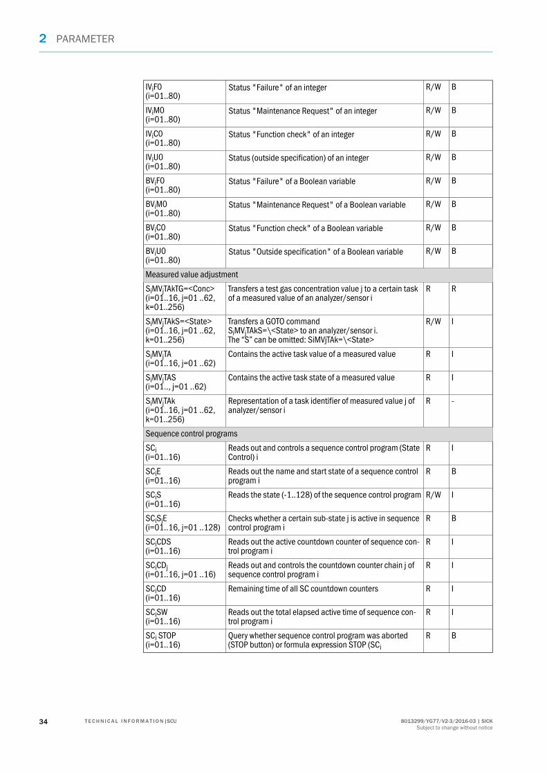
IViF0(i=01..80)
Status "Failure" of an integer R/W B
IViM0(i=01..80)
Status "Maintenance Request" of an integer R/W B
IViC0(i=01..80)
Status "Function check" of an integer R/W B
IViU0(i=01..80)
Status (outside specification) of an integer R/W B
BViF0(i=01..80)
Status "Failure" of a Boolean variable R/W B
BViM0(i=01..80)
Status "Maintenance Request" of a Boolean variable R/W B
BViC0(i=01..80)
Status "Function check" of a Boolean variable R/W B
BViU0(i=01..80)
Status "Outside specification" of a Boolean variable R/W B
Measured value adjustment
SiMVjTAkTG=<Conc>(i=01..16, j=01 ..62, k=01..256)
Transfers a test gas concentration value j to a certain task of a measured value of an analyzer/sensor i
R R
SiMVjTAkS=<State>(i=01..16, j=01 ..62, k=01..256)
Transfers a GOTO command SiMVjTAkS=\<State> to an analyzer/sensor i.The “S” can be omitted: SiMVjTAk=\<State>
R/W I
SiMVjTA(i=01..16, j=01 ..62)
Contains the active task value of a measured value R I
SiMVjTAS(i=01.., j=01 ..62)
Contains the active task state of a measured value R I
SiMVjTAk(i=01..16, j=01 ..62, k=01..256)
Representation of a task identifier of measured value j of analyzer/sensor i
R -
Sequence control programs
SCi (i=01..16)
Reads out and controls a sequence control program (State Control) i
R I
SCiE(i=01..16)
Reads out the name and start state of a sequence control program i
R B
SCiS(i=01..16)
Reads the state (-1..128) of the sequence control program R/W I
SCiSjE(i=01..16, j=01 ..128)
Checks whether a certain sub-state j is active in sequence control program i
R B
SCiCDS(i=01..16)
Reads out the active countdown counter of sequence con-trol program i
R I
SCiCDj(i=01..16, j=01 ..16)
Reads out and controls the countdown counter chain j of sequence control program i
R I
SCiCD(i=01..16)
Remaining time of all SC countdown counters R I
SCiSW(i=01..16)
Reads out the total elapsed active time of sequence con-trol program i
R I
SCi STOP(i=01..16)
Query whether sequence control program was aborted (STOP button) or formula expression STOP (SCi
R B
34 8013299/YG77/V2-3/2016-03 | SICKT E C H N I C A L I N F O R M A T I O N |SCUSubject to change without notice

PARAMETER 2
Test gases
TG, TGi(i=01..64)
Activation function for test gas i - -
TGiE(i=01..64)
Shows whether test gas i is released and the release signal present
R B
Input/output interfaces
AOi(i=01..96)
Output physical value (scaled) R/W R
AOiL(i=01..96)
Query of display limitLower limit when scaling an analog output (then required, e.g. when drift values are to be scaled in % for an analog output which is however scaled for mg/m3)
R R
AOiU(i=01..96)
Query of display limit Upper limit when scaling an analog output (then required, e.g. when drift values are to be scaled in % for an analog output which is however scaled for mg/m3)
R R
AOiO(i=01..96)
Direct value of current output 0..20 mA in mA R/W R
AOiOR(i=01..96)
Actual active display range R B
AIi(i=01..96)
Read in and converted physical value R R
AIiI(i=01..96)
Direct value of current input 0..20 mA in mA R R
DOi(i=01..128)
Activation signal for digital output before a possibly set inversion
R/W B
DOiO(i=01..128)
Direct relay state of switch signal output R/W B
DIi(i=01..96)
Input signal after a possibly set inversion R B
DIiI(i=01..96)
Direct switch state R B
NiMjAOk(i=0..08, j=01..16, k=01..02)
Node(i)Modul(j)AO(k) Output physical value (scaled)
R/W R
NiMjAOkL(i=0..08, j=01..16, k=01..02)
Node(i)Modul(j)AO(k) Query of display limitLower limit when scaling an analog output (then required, e.g. when drift values are to be scaled in % for an analog output which is however scaled for mg/m3)
R R
NiMjAOkU(i=0..08, j=01..16, k=01..02)
Node(i)Modul(j)AO(k) Query of display limitUpper limit when scaling an analog output (then required, e.g. when drift values are to be scaled in % for an analog output which is however scaled for mg/m3)
R R
NiMjAOkO(i=0..08, j=01..16, k=01..02)
Node(i)Modul(j)AO(k) Direct value of current output 0..20 mA in mA
R/W R
NiMjAOkR(i=0..08, j=01..16, k=01..02)
Node(i)Modul(j)AO(k) Actual active display range
R B
NiMjAIk(i=0..08, j=01..16, k=01..02)
Node(i)Modul(j)AI(k) Read in and converted physical value
R R
358013299/YG77/V2-3/2016-03 | SICK T E C H N I C A L I N F O R M A T I O N |SCUSubject to change without notice

2 PARAMETER
NiMjAIkI(i=0..08, j=01..16, k=01..02)
Node(i)Modul(j)AI(k) Direct value of current input 0..20 mA in mA
R R
NiMjDOk(i=0..08, j=01..16, k=01..02/03/04)[6]
Node(i)Modul(j)DO(k) Activation signal for digital output before a possibly set inversion
R/W B
NiMjDOkO(i=0..08, j=01..16, k=01..02/03/04)[6]
Node(i)Modul(j)DO(k) Direct relay state of switch signal output
R/W B
NiMjDIk(i=0..08, j=01..16, k=01..04)
Node(i)Modul(j)DI(k)Input signal after a possibly set inversion
R B
NiMjDIkI(i=0..08, j=01..16, k=01..04)
Node(i)Modul(j)DI(k)Direct switch state
R B
[1] Only analyzers/sensors supporting this function.[2] j=0 means: An optional bit has been set (group alarm).[3] To confirm a status, the status can also be described under its tag.[4] j=0 means: An optional bit has been set (group alarm).[5] To confirm a status, the status can also be described under its tag.[6] Depending on DO module used.
36 8013299/YG77/V2-3/2016-03 | SICKT E C H N I C A L I N F O R M A T I O N |SCUSubject to change without notice

PARAMETER 2
Remote control
MBOVii = 1 ... 650
Modbus output for Float32 according to IEEE754 or Int32 values (Input Register) R/W I/R[1]
MBOFi,i = 1 ... 500 Modbus output for status or flags (Discrete Inputs) R/W B
MBIVi,i = 1 ....50
Modbus input for Float32 according to IEEE754 or Int32 values (Holding Register) R I/R[1]
MBOFi,i = 1 ... 100 Modbus input for status or flags (Coil) R/W B
MBO01 ... MB62 Modbus output R/W I/R[1]
MBI01 ... MBI62 Modbus input R I
OPCO01 ... OPCO650 OPC output R/W I/R[2]
OPCI01 ... OPCI96 OPC input R I/R[2]
[1] Depending on Modbus parameter setting.[2] Depending on OPC parameter setting.
NTP Server
NTPD The last time drift between system clock and NTP [s] deter-mined and corrected R R
NTPE Connection state as Boolean value R B
378013299/YG77/V2-3/2016-03 | SICK T E C H N I C A L I N F O R M A T I O N |SCUSubject to change without notice

2 PARAMETER
2.5.8 Operators in formulas
Symbol Application[1] Value Description
INCor++
INC(op)
++op
I, R Incrementation of operand
DECor––
DEC(op)
––op
I, R Decrementation of operand
+ +op I, R Positive sign
– –op I, R Negative sign
** op1**op2 I, R Power
* op1*op2 I, R Multiplication
/ op1/op2 I, R Division
% op1%op2 I, R Modulo (remainder of an integer division)
+ op1+op2 I, R Addition
– op1–op2 I, R Subtraction
TOGGLEor//
TOGGLE(op)
//op
B Inverting (so-called “toggling”) of logical magnitude op[2]
CONTor>+
CONT(op)
>+op
B Logical variable op is activated or the time variable started
HALTor>–
HALT(op)
>–op
B Logical variable op is deactivated or the time variable stopped (and held)
STARTor!+
START(op)
!+op
B Time variable op is reset to the start value and started (op can be Stop Watch, Count Down or Time Function)
Stopor!–
STOP(op)
!–op
B Time variable op is only reset to the start value and started (op can be Stop Watch, Count Down or Time Function) (see page 30)
~ ~op B Complement creation (invert each bit: e.g. 10 → 01)
Bit operators
<< op1<<op2 I Left shift
>> op1>>op2 I Right shift
BANDor&
op1 BAND op2
op1&op2
I Bit-wise AND
BXORor^
op1 BXOR op2
op1^op2
I Bit-wise exclusive OR
BORor|
op1 BOR op2
op1|op2
I Bit-wise inclusive OR
Logical operators
LANDor&&
op1 LAND op2
op1&&op2
I, B AND
LXORor^^
op1 LXORop2
op1^^op2
I, B Exclusive OR
38 8013299/YG77/V2-3/2016-03 | SICKT E C H N I C A L I N F O R M A T I O N |SCUSubject to change without notice

PARAMETER 2
LORor||
op1 LOR op2
op1||op2
I, B Inclusive OR
LEor<=
op1 LE op2
op1<=op2
I, R, B Less than or equal to
GEor>=
op1 GE op2
op1>=op2
I, R, B Greater than or equal to
EQor==
op1 EQ op2
op1==op2
I, R, B Equal to
NEor!=
op1 NE op2
op1!=op2
I, R, B Unequal
LTor<
op1 LT op2
op1<op2
I, R, B Less than
GTor>
op1 GT op2
op1>op2
I, R, B Greater than
NOTor!
NOT(op)
!op
B Not
, (expr1, expr2, ...) Comma operator[3]
IF, THEN, ELSEor?, :
see “Statements”, page 40
= op1=op2 I, R, B Assignment
+= op1+=op2 I, R Assignment (addition)
–= op1–=op2 I, R Assignment (subtraction)
*= op1*=op2 I, R Assignment (multiplication)
/= op1/=op2 I, R Assignment (division)
%= op1%=op2 I Assignment (modulus)
&= op1&=op2 I Assignment (and)
^= op1^=op2 I Assignment (exclusive OR)
|= op1|=op2 I Assignment (inclusive OR)
[1] op (=operator) is the placeholder for this tag (e.g. RV25, SW33 see page 30)[2] Example see page 23[3] The expressions are processed from the left to the right. The result of the last expression is used further.
Symbol Application[1] Value Description
398013299/YG77/V2-3/2016-03 | SICK T E C H N I C A L I N F O R M A T I O N |SCUSubject to change without notice

2 PARAMETER
2.5.9 Order of precedence for formula operators
Priority of operators in descending sequence:
2.5.10 Statements
() alternative notation
INC (++), DEC ( ––), +, –, ~, NOT (!), HALT ( >–), CONT ( >+), STOP ( !–), START ( !+), TOGGLE ( //)
**
* / %
+ –
<< >>
LT (<), LE (<=), GT (>), GE (>=)
EQ (==), NE (!=)
BAND (&)
BXOR (^)
BOR (|)
LAND (&&)
LXOR (^^)
LOR (||)
? :
=, +=, –=, *=, /=, %=, &=, ^=, BOR (|), =
,
;
Application Description
IF (condition) THEN (stmt1) ENDIForIF (condition) THEN (stmt1) ELSE (stmt2) ENDIFor(condition) ? (stmt1) : (stmt2)
When the condition is fulfilled, statement1 is exe-cuted; otherwise statement2(Brackets mandatory, ENDIF mandatory)
function(arg) Syntax of a function call (see below: “Functions”)
var = expression Assignment of “expression” to the variable “var”
expression1; expression2;... expressionn Several “expressions” can be executed in a line. The result of the last expression is the end result
40 8013299/YG77/V2-3/2016-03 | SICKT E C H N I C A L I N F O R M A T I O N |SCUSubject to change without notice

PARAMETER 2
2.5.11 Mathematical functions in formulas
Function Value Description
abs (op) Absolute value of op
sgn (op) int Sign
ceil (op) int Round up (e.g.: 1.1 => 2.0)
floor (op) int Round down (e.g.: 1.9 => 1.0)
exp (op) float Exponential function ex
log10 (op) float Logarithm to basis 10
log (op) float Logarithm to basis e
sqrt (op) float Square root
rnd (op) float Random number
bnd (op) A number smaller than (–1) is set to (–1), a number greater than 1 to 1. The function has no effect on values between (–1) and 1
frac (op) float Decimal places of a float number
sin (op) float Sine
cos (op) float Cosine
tan (op) float Tangent
asin (op) float Arc Sine
acos (op) float Arc Cosine
atan (op) float Arc Tangent
atan2 (op) float atan2 (expression, assignment expression)Arc tangent of both variables
418013299/YG77/V2-3/2016-03 | SICK T E C H N I C A L I N F O R M A T I O N |SCUSubject to change without notice

2 PARAMETER
2.5.12 Validation result (Drift Check)
Tags available
Tag format
Examples
Tag (examples) Significance
S1MV1ZPV Drift measurement
S1Mv1ZPVSP Nominal value
S1Mv1ZPVD Deviation between measured value and nominal value
S1Mv1ZPVT Timestamp as integer 4 byte long UNIX value (in seconds since 1.1.1970)
Sensor Index Measured value
Index Optional: Specifica-tion on test medium source used
Drift vari-able
Index[1] Use Variable
S 1..16 MV 1..62 I=internalE=external
ZP[2]
RP[3]
CO[4]
1..13 V[5]
A[6]SP[7]
D[8]
T[9]
[1] Only for several reference points, depending on analyzer[2] Zero point, reference point, contamination[3] Reference point[4] Contamination (measure for contamination of optics)[5] Validation[6] Adjustment[7] Nominal value[8] Deviation nominal value - measured value[9] Timestamp, otherwise drift value
Tag (examples) Significance
S1MV1ZPV Validation of zero point drift
S1Mv1RPVD Deviation of drift from reference point to nominal value
42 8013299/YG77/V2-3/2016-03 | SICKT E C H N I C A L I N F O R M A T I O N |SCUSubject to change without notice

PARAMETER 2
2.5.12.1 Exporting recorded data
● Transfer data to PC: Menu in SOPAS ET: “File Upload“.The data can then be loaded into Excel for example.
● File name: “DriftTable.txt“.● The file contains the drift values in chronological sequence.● The data are separated by commas.● Number values have a dot as decimal point.● Number of entries: 2 times 4096 entries:
When an overflow occurs, the oldest 4096 entries are deleted and new entries written. This means at least the last 4096 entries are available. This corresponds to a timeframe of 85 days when 3 entries from 16 sensors are recorded daily.
● The file can contain data where recording is obligatory so that deletion is not available. Deletion of data no longer required must be done outside the SCU.
File format
● Column “Tag”, together with column “Time”, provide a sort option to create chronological sequences of drifts of a particular measured variable.
Time Loca-tion[1]
Device SN Compo-nent
Type Actual value
Nominal value
Unit Status[2] Tag
YYYY-MM-DD hh:mm
11300 Analyzer 1 00000000
CO Zero adjust-ment with gas
0,1234 0 ppm ---M- S01MV01ZPJ
[1] Designation of installation location, e.g.: “Stack 1“[2] Classification according to NAMUR: F, M, C, U
438013299/YG77/V2-3/2016-03 | SICK T E C H N I C A L I N F O R M A T I O N |SCUSubject to change without notice

2 PARAMETER
2.6 Bug(s) in formula(s) (menu)
Menu: System Control Unit/Diagnosis/Bug(s) in Formula(s)
● Formulas are checked when executed. They are therefore not checked during creation.
● Erroneous formulas are signaled in SOPAS ET and the error is displayed in the Diagnosis menu.
A LED labeled “Bug(s) in Formula(s)” goes on in SOPAS ET.● Measured values not available due to a connection interruption for example, also trigger
a signal.
● Deleting a corrected formula: – Press “Clear all entries”– or it is removed automatically the next time the formula is processed.
● Maximum 3 erroneous formulas each with maximum 4 error causes are displayed. Further erroneous formulas are displayed when the formulas previously displayed are corrected.
Erroneous formulas are only signaled and displayed in SOPAS ET.The menu of the SCU user interface shown below only serves as assistance.
The “Bug(s) in formula(s)” signal must not therefore always be caused by an errone-ous formula.Button “Tag Check” serves to suppress the check.
Designation Remark
Refresh The cause shown for an erroneous formula is not automatically refreshed:Press "Refresh".
Clear all entries To clear all entries after correcting formulas:Press “Clear all entries”
Tag Check When desired, the validity check of the tag active as from the start of the SCU start can be switched off by deactivating “Tag Check” in menu “SCU_P100/Diagnosis/Bug(s) in Formula(s)”.
NOTE: Deactivating the “Tag Check” also deactivates formula execution. “Tag Check” must be activated during normal operation.
No formula bugs found The formula is correct when this appears after “Refresh”.
/SCU/Diagnosis/Bug(s) in Formula(s)
SCUAnalyzer 1 Measure
Refresh
Clear all entries
No formula bugs found
Tag Check
44 8013299/YG77/V2-3/2016-03 | SICKT E C H N I C A L I N F O R M A T I O N |SCUSubject to change without notice

PARAMETER 2
2.7 Status
Menu: System Control Unit/Parameter/Status
These menus control the status bar of the SCU.
For example: Failure (S0Fi):
Failure (S0Fi)
Maintenance request (S0Mi)
Function check (S0Ci)
Out of Spec (S0Ui)
/System Control Unit/Parameter/Status/
SCUAnalyzer 1 Measure
Designation Remark
Index Consecutive number of status.
Name This entry is recorded in the logbook.
Formula If a formula is “TRUE”, the status field appears in the status bar and is entered into the logbook.If a formula is “FALSE”, the status field disappears from the status bar and is entered into the logbook.
Save Mark Edit Copy Replace Next
/System Control Unit/.../Status/Failure (S0Fi)
SCUAnalyzer 1 Measure
Index Name Formula
1 Cooler error (N4M2DI3)EQ(1)
2 Probe heating error(N2M6DI7)LAND(N2M6
DI8)
3
etc.
458013299/YG77/V2-3/2016-03 | SICK T E C H N I C A L I N F O R M A T I O N |SCUSubject to change without notice

2 PARAMETER
2.8 Variables and functions
Menu: System Control Unit/Parameter/Variables and Functions
Timer
Limit Values (LIi)
Real Values (RVi)
Real Constants (RCi)
Integer Values (IVi)
Integer Constants (ICi)
Boolean Values (BVi)
Filtered Values (FVi)
Help Values (HVi)
/System Control Unit/.../Variables and Functions/
SCUAnalyzer 1 Measure
see page 47
see page 51
see page 51
see page 52
see page 52
see page 53
see page 53
see page 54
see page 55
The current values (results) for variables and functions are used:● In the formula editor see page 24.● In Measuring screens (parametrization see page 8).
46 8013299/YG77/V2-3/2016-03 | SICKT E C H N I C A L I N F O R M A T I O N |SCUSubject to change without notice

PARAMETER 2
2.8.1 Timer
Menu: System Control Unit/Parameter/Variables and Functions/Timer
2.8.1.1 Stop watches (SWi)
Menu: System Control Unit/Parameter/Variables and Functions/Timer/Stop Watches
Increments seconds beginning with 0.
2.8.1.2 Count Downs (CDi)
Menu: System Control Unit/Parameter/Variables and Functions/Timer/Count Downs
Decrements seconds beginning with the start value.
Stop Watches (SWi)
Count Downs (CDi)
Time Functions (TFi)
Cyclic Trigger (CTi)
/System Control Unit/.../Timer/
SCUAnalyzer 1 Measure
see page 47
see page 47
see page 48
see page 50
Designation Remark
Index Consecutive number of the stop watch (SW01, SW02, ...).
Name Freely selectable.
Save Mark Edit Copy Replace Next
/System Control Unit/.../Timer/Stop Watches (SWi)
SCUAnalyzer 1 Measure
Index Name
1 ZERO Timer
2 SPAN Timer
3 O2-SPAN Timer
etc.
Designation Remark
Index Consecutive number of the count down (CD01, CD02, ...).
Name Freely selectable.
Start value Start value [s].
Save Mark Edit Copy Replace Next
/System Control Unit/.../Timer/Count Downs (CDi)
SCUAnalyzer 1 Measure
Index Name Start value [s]
1 Startup max 3600
2 Startup min 30
3 0
etc.
478013299/YG77/V2-3/2016-03 | SICK T E C H N I C A L I N F O R M A T I O N |SCUSubject to change without notice

2 PARAMETER
2.8.1.3 Time functions (TFi)
Menu: System Control Unit/Parameter/Variables and Functions/Timer/Time Functions
Designation Remark
Index Consecutive number of the time function (TF01, TF02, ...).
Name Freely selectable.
Type See below[1].
Source Tag (e.g.: DI01, BV0).
Repeating Period [Seconds]
Switch-On Period [Seconds]
Acknowledge The time functions ALARM, DELAY and SYNC can be deactivated with an acknowledge signal to shorten the hold time set. If the acknowledge signal is already active when the time function switches from OFF to ON, the time function then runs for at least 1 SCU cycle (1 s) before switching OFF again.
Switch-On Delay [Seconds]
Release Delay [Seconds]
Switch-On Time (For ”Type” ”Alarm”) [hh:mm:ss]
Save Mark Edit Copy Replace Next
/System Control Unit/.../I/O/Data/Analog Output (AOi)
SCUAnalyzer 1 Measure
Index Name Type Source Repeating Period Switch-On PeriodAcknowledge Switch-On Delay [s] Release Delay [s] Switch-On Time
1 IR ZERO Adjust Trigger Alarm 0 30 ON 0 0 12:12:00
2 O2-SPAN Trigger None 0 10 OFF 0 0 6:00:00
3 O2-CHECK Trigger None 0 10 OFF 0 0 19:00:00
etc.
48 8013299/YG77/V2-3/2016-03 | SICKT E C H N I C A L I N F O R M A T I O N |SCUSubject to change without notice

PARAMETER 2
[1]Type:
Source
DelayWhen “Source” occurs: Is delayed by “Switch-On Delay” and then switched on for “Switch-On Period”.
SyncBecomes active with “Repeating Period” for “Switch-On Period”. Synchronized to “Source”. When “Source” is active, the sync trigger is not switched on.When “Source” becomes inactive, the sync trigger switches again.
DebouncingFollows the signal of “Source” when it was active without interruption for the set “Switch-On Delay”.Switches off when “Source” was inactive without interruption for the set “Release Delay”.
AlarmSwitches on at the “Switch-On Time” for the “Switch-On Period”.
Switch-OnDelay Switch-On
Period
Switch-OnPeriod
RepeatingPeriod
Deactivation ofsync trigger
Falling edge of source starts sync trigger
Switch-on delay longer than pending source signal
Switch-OnDelay
ReleaseDelay
Switch-OnTime
Switch-On Period
498013299/YG77/V2-3/2016-03 | SICK T E C H N I C A L I N F O R M A T I O N |SCUSubject to change without notice

2 PARAMETER
2.8.1.4 Cyclic trigger (CTi)
Menu: System Control Unit/Parameter/Variables and Functions/Timer/Cyclic Trigger
Start cyclic trigger (CTi) periodically.
Control options Remark
x=CTi Specifies the remaining time of an active CTi. The result is 0 when inactive.
START (CTi)or!+CTi
Starts the CTi immediately. Cycle and next start time remain unchanged.
Save Mark Edit Copy Replace Next
/System Control Unit/.../Timer/Cyclic Trigger (CTi)
SCUAnalyzer 1 Measure
Index Name Active Period Unit 1. Start Delay [s]
1 NULL 0 Hour(s) 2000-01-01 00:00 0
2 NULL 0 Hour(s) 2000-01-01 00:00 0
3 NULL 0 Hour(s) 2000-01-01 00:00 0
etc.
Designation Remark
Index Consecutive number of the cyclic trigger (CT01, CT02, ...) .
Name Freely selectable.
Active Checkmark: Trigger is active.
Period Intermittence; specifies a multiple of minutes, hours, days or weeks.
Unit Minutes, hours, days, weeks.
1. Start Start timeFollowing entries are possible:– YYYY-MM-DD hh:mm
Complete transfer of date and time– hh:mm
Current SCU date is used as date– “No entry”
Entry timepoint used as date and time.Recommendation: To check the inputs made, an “Upload all parameters from Device” is recommended after successful parameterization (Menu: Sys-tem Control Unit/Upload all parameters from Device) The completed specifications then appear.
Delay [s] Duration during which the CTi is active.
Current device time[1] Current device time
[1]In the “Edit” menu
50 8013299/YG77/V2-3/2016-03 | SICKT E C H N I C A L I N F O R M A T I O N |SCUSubject to change without notice

PARAMETER 2
2.8.2 Limit values (LIi)
Menu: System Control Unit/Parameter/Variables and Functions/Limit Values
2.8.3 Real values (RVi)
Menu: System Control Unit/Parameter/Variables and Functions/Real Values
Designation Remark
Index Consecutive number of the limit value (LI01, LI02, ...).
Source Tag.
Threshold Threshold.
Hysteresis Hysteresis [threshold unit].
Filter type Underflow/overflow.
Save Mark Edit Copy Replace Next
/System Control Unit/.../Limit Values (LIi)
SCUAnalyzer 1 Measure
Index Source Threshold Hysteresis Filter type
1 rv1 1.5E01 1.5E01 Overflow
2 rv2 4.5E01 4.5E01 Overflow
3 rv4 5.0E01 5.0E01 Overflow
etc.
Designation Remark
Index Consecutive number of the real vaue (RV01, RV02, ...).
Name Value name. Freely selectable.
Unit Unit. Freely selectable.
Gas Condition Freely selectable. Example: Dry, standard state, operational state.
Start Value Start value after start of the SCU.
Save Mark Edit Copy Replace Next
/System Control Unit/.../Real Values (RVi)
SCUAnalyzer 1 Measure
Index Name Unit Gas Condition Start Value
1 CO mg/m3 Norm Norm 0.0E00
2 SO2 mg/m3 Norm Norm 0.0E00
3 NO mg/m3 Norm Norm 0.0E00
etc.
518013299/YG77/V2-3/2016-03 | SICK T E C H N I C A L I N F O R M A T I O N |SCUSubject to change without notice

2 PARAMETER
2.8.4 Real constants (RCi)
Menu: System Control Unit/Parameter/Variables and Functions/Real Constants
2.8.5 Integer Values (IVi)
Menu: System Control Unit/Parameter/Variables and Functions/Integer Values
Designation Remark
Index Consecutive number of the real comma constant (RC01, RC02, ...).
Name Name. Freely selectable.
Unit Unit. Freely selectable.
Gas Condition Freely selectable. Example: Dry, standard state, operational state.
Constant Numeric value. Can be overwritten by the input signal.
Source Tag.
Save Trigger Tag.
Save Condition Rising/falling edge triggers overwriting the constant by the input signal.
Save Mark Edit Copy Replace Next
/System Control Unit/.../Real Constants (RCi)
SCUAnalyzer 1 Measure
Index Name Unit Gas Condition Constant Source Save Trigger Save Condition
1 0.0E00 RisingEdge
2 0.0E00 RisingEdge
3 0.0E00 RisingEdge
etc.
Designation Remark
Index Consecutive number of the integer value (IV01, IV02, ...).
Name Name. Freely selectable.
Start Value Start value after start of the SCU.
Save Mark Edit Copy Replace Next
/System Control Unit/.../Integer Values (IVi)
SCUAnalyzer 1 Measure
Index Name Start Value
1 OpStateSensor(s2s) 0
2 0
3 0
etc.
52 8013299/YG77/V2-3/2016-03 | SICKT E C H N I C A L I N F O R M A T I O N |SCUSubject to change without notice

PARAMETER 2
2.8.6 Integer constants (ICi)
Menu: System Control Unit/Parameter/Variables and Functions/Integer Constants
2.8.7 Boolean values (BVi)
Menu: System Control Unit/Parameter/Variables and Functions/Boolean Values
Designation Remark
Index Consecutive number of the integer constants (IC01, IC02, ...).
Name Name. Freely selectable.
Constant Numeric value. Can be overwritten by the input signal.
Source Tag.
Save Trigger Tag.
Save Condition Rising/falling edge triggers overwriting the constant by the input signal.
Save Mark Edit Copy Replace Next
/System Control Unit/.../Integer Constants (ICi)
SCUAnalyzer 1 Measure
Index Name Constant Source Save Trigger Save Condition
1 0 RisingEdge
2 0 RisingEdge
3 0 RisingEdge
etc.
Designation Remark
Index Consecutive number of the Boolean value (BV01, BV02, ...).
Name Name. Freely selectable.
Start value Checkmark: “True” = 1 (integer).No checkmark: “False” = 0 (integer).
Save Mark Edit Copy Replace Next
/SCU/.../Variables and Functions/Boolean Values (BVi)
SCUAnalyzer 1 Measure
Index Name Start value
1 Measure
2 Failure
3 Maintenance
4 Check
5 Uncertain
6 Extended
538013299/YG77/V2-3/2016-03 | SICK T E C H N I C A L I N F O R M A T I O N |SCUSubject to change without notice
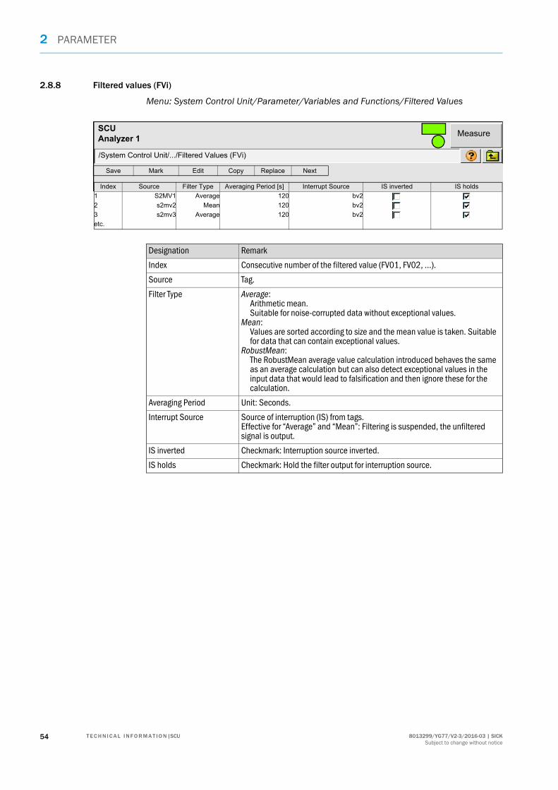
2 PARAMETER
2.8.8 Filtered values (FVi)
Menu: System Control Unit/Parameter/Variables and Functions/Filtered Values
Designation Remark
Index Consecutive number of the filtered value (FV01, FV02, ...).
Source Tag.
Filter Type Average: Arithmetic mean. Suitable for noise-corrupted data without exceptional values.
Mean: Values are sorted according to size and the mean value is taken. Suitable for data that can contain exceptional values.
RobustMean: The RobustMean average value calculation introduced behaves the same as an average calculation but can also detect exceptional values in the input data that would lead to falsification and then ignore these for the calculation.
Averaging Period Unit: Seconds.
Interrupt Source Source of interruption (IS) from tags.Effective for “Average” and “Mean”: Filtering is suspended, the unfiltered signal is output.
IS inverted Checkmark: Interruption source inverted.
IS holds Checkmark: Hold the filter output for interruption source.
Save Mark Edit Copy Replace Next
/System Control Unit/.../Filtered Values (FVi)
SCUAnalyzer 1 Measure
Index Source Filter Type Averaging Period [s] Interrupt Source IS inverted IS holds
1 S2MV1 Average 120 bv2
2 s2mv2 Mean 120 bv2
3 s2mv3 Average 120 bv2
etc.
54 8013299/YG77/V2-3/2016-03 | SICKT E C H N I C A L I N F O R M A T I O N |SCUSubject to change without notice

PARAMETER 2
2.8.9 Help values (HVi)
Menu: System Control Unit/Parameter/Variables and Functions/Help Values
The SCU sends a value from another analyzer or an analog input to an analyzer. The significance is specified by the receiving analyzer.
Designation Remark
Index Consecutive number of the help values (HV01, HV02,...).
Source Tag.Example: Analog input, Modbus, etc.
Sensor No. Analyzer to which the value is sent.
Help Value No. Help value number of the analyzer (→ Data Sheet of the analyzer).
Save Mark Edit Copy Replace Next
/System Control Unit/.../Help Values (HVi)
SCUAnalyzer 1 Measure
Index Source Sensor No. Help Value No.
1 AI03 2 1
2 AI04 2 1
3 NULL 0 0
etc.
558013299/YG77/V2-3/2016-03 | SICK T E C H N I C A L I N F O R M A T I O N |SCUSubject to change without notice

2 PARAMETER
2.9 Sequence control programs and countdowns
Menu: System Control Unit/Parameter/Sequence Controls
Serves to program event-controlled sequence control programs.
2.9.1 How sequence control programs function
Sequence control programs support automatic conditional sequences. 16 sequence con-trol programs can be programmed in the SCU. 192 program sections can be programmed for each sequence control program. Each program section contains an “action” that can be linked to a “condition”. Program sections are chained into a program according to their “step” number see “Program flow”, page 57).
2.9.1.1 Starting sequence control programs
● A sequence control program starts automatically when the “start condition” and “enable condition” are met. These conditions are checked every second during operation when the sequence control program is idle. The sequence control program runs continuously when the start and enable conditions are set to “true”.
● Sequence control programs can be started directly with a tag in a formula term (see “Tags (formula elements)”, page 30).
● Sequence control programs can also be started directly using the “Start” button in the Edit function, e.g. for test purposes.
2.9.1.2 Aborting sequence control programs
Running sequence control programs can be aborted with a Stop command in a formula term. This allows aborting a sequence control program automatically when a certain condi-tion occurs – e.g. when an internal status or the status of a digital input changes.
The “step after aborting” specifies which program step is to follow automatically after a stop. Normally, a sequence that reestablishes the normal operating state is linked.
Number
Sequence Controls
CountDown
Manual sequences
/System Control Unit/Parameter/Sequence Controls
SCU Measure
see page 59
see page 59
see page 66
see page 66
Sequence control programs can also be aborted using the “Stop” button in the Edit function.
56 8013299/YG77/V2-3/2016-03 | SICKT E C H N I C A L I N F O R M A T I O N |SCUSubject to change without notice

PARAMETER 2
2.9.1.3 Program flow
Step numbers
Each program section is assigned a step number. This step number is the address of the program section within the sequence control program. It does not have to be identical with the index number of the program section.
Step numbers are principally freely selectable within the range 1 … 192. It is however advantageous from a technical viewpoint when the step numbers are in consecutive sequence.
Rules for step numbers
● Sequence control programs call up the program section with step number “1” automati-cally when starting.
● Each program section has a “subsequent step” - this is the step number of the program section to be called next.
● Subsequent step “0” means: Stop the sequence control program after the “action”.● Subsequent step “–1” means: Abort the sequence control program and execute the
“step after aborting”.
Program sections with the same step number
Several program sections can have the same step number. This results in alternative pro-gram steps that are valid in their “Index” number sequence.
When a certain step number is called and several program sections with this step number exist, the sequence control program initially attempts to execute the first of these program sections (program section with the lowest “Index” number).
● This program section is then performed when the start and enable conditions are met; then the “subsequent step” is called.
● If the start and enable conditions for the program section are not met, the next program section with the same step number is called (in “Index” number sequence).
This flow is valid for all program sections with the same step number.
Process flow control with a countdown timer
To create a delay time or time lag in a sequence control program:
1 Start one of the countdown timers as an “action” in a program section (SCCDi) (see “Count Down (SCiCD, SCiCDj)”, page 66). Enter the step number of the next program section as “subsequent step”.
2 Define a “start condition” in this next program section that starts the “action” as soon as the countdown time elapses.
Regular start using a cyclic trigger
Starting a sequence control program in regular intervals:
▸ Assign step number “1” to the program section with which the sequence control pro-gram should start.
▸ Enter a “subsequent step” in each program section.
Subsequent step “0” instructs the sensors to continue measuring operation (corre-sponds to term “SiMVjTAkS=0” see “Tags (formula elements)”, page 30). This prevents the sensors being blocked by an ongoing “action”.
578013299/YG77/V2-3/2016-03 | SICK T E C H N I C A L I N F O R M A T I O N |SCUSubject to change without notice

2 PARAMETER
1 Set a cyclic trigger accordingly (→ Operating Instructions SCU “Parameter settings/Vari-ables and Functions/Timer”).
2 Inquire the status of this cyclic trigger in a sequence control program as start condition (formula term: “(CTi)NE(0)“).
2.9.1.4 Variable parameters in sequence control programs
Purpose of variable parameters
A value or a formula term can be assigned to a variable parameter. This is done using a for-mula term. When the variable parameter is used in a formula term, the variable parameter replaces the value or formula term assigned there.
Adding a variable parameter
Variable parameters have the following form in a formula term in a sequence control pro-gram
or
Determining the variable parameters
The actual values or terms of the variable parameters are determined in a different for-mula term by attaching the parameter values to an “SCi” tag which changes the state of the sequence control program (Write command). All values of the variable parameters are determined at the same time in each case.
The values are grouped in [square brackets] and separated with “\” (backslash). The [bracket] term is then attached to an “SCi” write tag (see “Example for variable parame-ters”).
Example for variable parameters
● Variable parameters “#0\”, “#1\” and “#2\” are used in a sequence control program.● The following formula term is performed: START(SC2)[\7\BVO9=1].
Effect:
a) The following assignments are applicable in sequence control program SC2:
b) Sequence control program SC2 starts.
#N\ N = variable number (0/1/2/…); example: #3\
#N[text]\ N = variable number, text = comment
Parameter is replaced with
#0\ Empty
#1\ 7
#2\ BVO9=1
Numbering of the variable parameters starts with “0”.
58 8013299/YG77/V2-3/2016-03 | SICKT E C H N I C A L I N F O R M A T I O N |SCUSubject to change without notice

PARAMETER 2
2.9.2 Number
Menu: System Control Unit/Parameter/Sequence Controls/Number
Number of sequence control programs shown (to ensure clarity).
The total number of sequence control programs is 16.
All 16 sequence control programs are executed.
2.9.3 Sequence control programs (SCi)
Menu: System Control Unit/Parameter/Sequence Controls/Sequence Controls
Serves to program event-controlled sequence control programs.
● Events are, for example:– Time-controlled events– Switching input signals– State of a connected sensor.
● Max. number of sequence control programs: 16● Programming is split into 3 groups:
– Sequence control program “Start” (see page 64)– Sequence control program (see page 65)– Sequence control program “Abort” (see page 65)
● The initial state of a sequence control program is start state 0.
/System Control Unit/Parameter/Sequence Control
SCU Measure
1Specification sequence control program and
598013299/YG77/V2-3/2016-03 | SICK T E C H N I C A L I N F O R M A T I O N |SCUSubject to change without notice

2 PARAMETER
2.9.3.1 Control options
Control options Remark
x=SCi Reads out the name and (active) state of a sequence control program
START(SCi)or!+SCi
Resets and starts a sequence control program. Corresponds to the START button
STOP(SCi)or!-SCi
Resets and stops a sequence control program. Corresponds to the STOP button
HALT(SCi)or>-SCi
Effect of the Pause button
CONT(SCi)or>+SCi
Activation (= end of the pause state) of a sequence control program. Corresponds to the CONTINUE button
x=SCiE Reads out the name and start state of a sequence control program
SCiS=<State> Direct branch to a state of the sequence control program
x=SCiS Reads out the state of a sequence control program
x=SCiSjE Checks whether a certain sub-state j is active in sequence control program i
x=SCiCDS Reads out the active countdown counter
x=SCiCDj Reads out the remaining time for a countdown counter
START(SCiCDj)or!+SCiCDj
Resets and starts the CD chain of a sequence control program as from a certain position
STOP(SCiCDj)or!-SCiCDj
Resets and stops the CD chain of a sequence control program at a certain position
x=SCiCD Reads out the non-elapsed total remaining time of the countdown counter chain
HALT(SCiCD)or>-SCiCD
Deactivates the countdown counter chain during sequence control program processing
CONT(SCiCD)or>+SCiCD
Reactivates the countdown counter chain of a sequence control program
x=SCiSW Reads out the elapsed active time of the sequence control program
60 8013299/YG77/V2-3/2016-03 | SICKT E C H N I C A L I N F O R M A T I O N |SCUSubject to change without notice

PARAMETER 2
2.9.3.2 Parameter transfer
Transferring one parameter from the Formula editor to a sequence control program
The transfer runs via the Formula editor resp. in the sequence control program.
Specification in the Formula editor: SC<n> parameter after the tag.
Parameters are in square brackets and separated with \ (backslash).
Example:
Formula editor: START(SC2)[\7\DO9=1] Transfers the following parameters:
Parameter 0: EmptyParameter 1: 7Parameter 2: DO9=1
and starts the SC2 immediately
Parameter acceptance by the sequence control program from the Formula editor
The sequence control program accepts the parameter:
#<Parameter index>[<comment>]\
Example:
Sequence control program: #1\
Effect The sequence control program uses Parameter 1 (in the example above: 7) where “#\1” is replaced by “7” before a row is evaluated.
618013299/YG77/V2-3/2016-03 | SICK T E C H N I C A L I N F O R M A T I O N |SCUSubject to change without notice

2 PARAMETER
2.9.3.3 Example 1: Sequence control program
Example 1: Sequence control program for feeding test gas
The representations as from see “Sequence control program: Start”, page 64 refer to this example.
● Purpose: Temporary feeding of a test gas instead of the sample gas.● Sequence control program: SC2.● Countdown timer used: CD1.● Digital output DO11 controls the sample gas valve. Variable BV11 controls the switching
state.● Digital output DO12 controls the test gas valve. Variable BV12 controls the switching
state.
Fig. 2: State diagram of a simple time-controlled gas feed
62 8013299/YG77/V2-3/2016-03 | SICKT E C H N I C A L I N F O R M A T I O N |SCUSubject to change without notice

PARAMETER 2
2.9.3.4 Example 2: State diagram
Example 2: State diagram of a fill level monitor
● Specification:– The container must have reserves when the system starts.– Stop filling when container threatens to overflow.– Before an overflow can occur, it must be signaled that the container needs to be emp-
tied.● Situation: (The fill level monitor is connected to N2M04DI02)
– Container still has reserve: (N2M04DI02)EQ(0)– Empty container: (N2M04DI02)EQ(1)– Container threatens to overflow: (N2M04DI02)EQ(1) since more than a day (86400
seconds)● Associated statuses
– Ready for measurement– Maintenance request (signaled via BV01)– Failure (signaled via BV02)
Fig. 3: State diagram of a fill level monitor
0System start
1Initialization
2Ready for measurement
4Failure
5Maintenance
Container still has reserve(N2M04DI02)EQ(0)
------BV01=0; BV02=0
Container threatens to overflow(N2M04DI02)EQ(1)
------BV01=1; BV02=1
Empty the container((N2M04DI02)EQ(1)) LAND (SW01 > 86400)
------BV01=1; BV02=1
Container still has reserve(N2M04DI02)EQ(0)
------BV01=0; BV02=0
Container threatens to overflow(N2M04DI02)EQ(1)
------BV01=1; BV02=0; START(SW01)
638013299/YG77/V2-3/2016-03 | SICK T E C H N I C A L I N F O R M A T I O N |SCUSubject to change without notice

2 PARAMETER
2.9.3.5 Sequence control program: Start
(Example according to see “Example 1: Sequence control program”, page 62)
Designation Remark
Name Freely selectable.
Start Starts a sequence control program. Continuous operation: TRUE or 1. Enable is checked for before the start.
Enable Enable signal for the sequence control program. TRUE or 1 also possible.
Actual State Name and state number.
CD Countdown counter: Name and remaining time.NULL and 0:00 are shown when all counters have run down.
SW Stopwatch: Total elapsed run-time of the sequence control program.
Start Starts a sequence control program without considering the enable signal.
Pause Interrupts a running sequence control program.
Stop Terminates a running sequence control program.
Continue Continue (after Pause).
/System Control Unit/Parameter/.../Sequence Control Start2
SCU Measure
ExampleName
NULL
0
Actual State
Stop
--:--:--
CD
SW
SW
Start
DI1Start
Pause
Enable
Stop
Continue
16:43:46
TRUE
64 8013299/YG77/V2-3/2016-03 | SICKT E C H N I C A L I N F O R M A T I O N |SCUSubject to change without notice

PARAMETER 2
2.9.3.6 Sequence control program
(Example see “Example 1: Sequence control program”, page 62)
2.9.3.7 Sequence control program abort
(Example see “Example 1: Sequence control program”, page 62)
“Abort” is inquired before a state change is checked.
Designation Remark
Index Consecutive numbering.The indices are processed from the highest to the lowest priority.
State Number of a state 1..127. The active state can be queried with SCiS.An individual line (index) must be programmed for each branch when a state has different subsequent states.
Name State identifier.
Condition Check whether a state transition should take place. Expression according to the Formula editor (see “Menu functions for formu-las”, page 24).
Action Carried out when the condition is true.
NextState Next state. 0: Switch to start state. -1: Perform exception action, then start state.
Save Mark Edit Copy Replace Next
/System Control Unit/Parameter/.../Sequence Control Start2 (SC2)
SCUMeasure
Index State Name Condition Action NextState
1 1 Reset TRUE DO11=0;DO12=0 10
2 10 READY4PROCESSING DI3 DO12=1;!+SC2CD1 11
3 11 PROCESSING (SC2CD1)EQ(0) DO11=0;DO12=0 10
4 0 NULL NULL NULL 0
Designation Remark
State -1: Abort and switch to start state 0.
Name State identifier.
Condition Check whether a state transition should take place. Expression according to the Formula editor (see page 24).
Action Carried out when the condition is true.
NextState Next state is start state 0.
/System Control Unit/Parameter/.../Sequence Control Start2
SCU Measure
-1State
DO11=0;DO12=0
0
Action
NextState
StopNameCondition DI4
658013299/YG77/V2-3/2016-03 | SICK T E C H N I C A L I N F O R M A T I O N |SCUSubject to change without notice
2 PARAMETER
2.9.4 Count Down (SCiCD, SCiCDj)
Menu: System Control Unit/Parameter/Sequence Controls/CountDown
Each sequence control program has a countdown chain which can be used to control a sequence control program.
The countdown chain starts when the sequence control program starts.
The following data are available:
● Remaining run-time for a single counter (SCiCDj).● Remaining run-time for the complete counter chain (SCiCD).
2.9.5 Manual adjustments (MAL)
Menu: System Control Unit/Parameter/Sequence Controls/Manual Adjust
This menu serves as starting point for the Manual Adjust menu (→ Operating Instructions SCU)
Designation Remark
Index Consecutive numbering.
Name Name.
Time Counter duration [s] before the next one starts.
Save Mark Edit Copy Replace Next
/System Control Unit/.../Sequence Control 2/CountDown (SC2CD)
SCU Measure
Index Name Time [s]
1 t(PROCESSING) 10
2 NULL 0
3 NULL 0
etc.
Designation Remark
Index The index is passed as parameter P5 when the sequence control program to be started is selected and can be used there, for example, to branch to a par-ticular state.
START(SCi)or!+SCi
Index of the sequence control program that can be started in Manual Adjust.
Name [0\..] The sequence control program identifier can be overwritten with this entry. The entry is passed to the sequence control program as P0 (→ Menu: Sys-tem Control Unit/Maintenance/Manual Adjust).
Save Mark Edit Copy Replace Next
/System Control Unit/.../Manual Adjust
SCU Measure
Index !+SC Name [0\..]
1 t(PROCESSING) 10
2 NULL 0
3 NULL 0
etc.
66 8013299/YG77/V2-3/2016-03 | SICKT E C H N I C A L I N F O R M A T I O N |SCUSubject to change without notice

PARAMETER 2
2.9.5.1 Transferring the parameter TGiCj to SCi
The Parameter list generated internally and passed to an SC when the Start button is acti-vated is available as Parameter #6\.
The following call is generated:
START(SCi)\[<Name>\TGj\Si\SiMVj\SiMVjTAk\<MALIdx>\TGiCj]
678013299/YG77/V2-3/2016-03 | SICK T E C H N I C A L I N F O R M A T I O N |SCUSubject to change without notice

2 PARAMETER
2.10 Test gas table (TGi)
Menu: System Control Unit/Parameter/Test Gas Table
The test gas table contains the following information:
● Number of the gas cylinder and which gas components it contains.● Concentration, unit and the required purge time for each gas component.● For each gas component, the specification which adjustment is to be performed on
which measuring component.● Information on opening and closing the gas path.● Prerequisites for enabling the use of the gas.
The concentration values are transferred automatically to the analyzers entered.
● After connection.● After changes.● After START(TGi ), START(TGi Cj), CONT(TGi , CONT(TGi Cj).
Access via tags within formulas
Nomenclature:
● TGi = test gas cylinder No. 1..64.● Ci = Gas components in a test gas cylinder; these can be read out and activated● Si = State which the measuring components should have during gas adjustment with the
gas component.● CDi= Count Down/ Downwards counters for monitoring the purge time of a gas compo-
nent. These can be read out and activated.● Ei = Enabled monitoring of a gas component.
Save Mark Edit Copy Replace Next
/System Control Unit/Parameter/Test Gas Table
SCUAnalyzer 1 Measure
Index Cylinder No. Name Concentration Unit t(Purge) [s] Use Start Stop Active Enable
1 0 NULL 0.0E00 ppm 0 NULL NULL NULL FALSE
2 0 NULL 0.0E00 ppm 0 NULL NULL NULL FALSE
3 0 NULL 0.0E00 ppm 0 NULL NULL NULL FALSE
etc.
68 8013299/YG77/V2-3/2016-03 | SICKT E C H N I C A L I N F O R M A T I O N |SCUSubject to change without notice

PARAMETER 2
Designation Remark
Index Test gas number.
Cylinder No. Number of test gas cylinder. One test gas cylinder can contain several test gases.
Name Test gas name.
Concentration Test gas concentration.Only specify when the analyzer supports this function.
Unit Unit of test gas (for information).
t(Purge) [s] Pre-purge time. Can, for example, be checked in sequence control programs as downward counter.
Use Assignment of the gas to the measured values and their tasks as a list, here, e.g. S2MV1TA1.Only specify when the analyzer supports this function.
Start Enables a test gas.
Stop Stops a test gas.
Active Checkmark set: “Start” execution allowed. Otherwise not allowed.“Enable Signal” must also be “TRUE”.
Enable “Start column” release by:- External signal or - setting TRUE or 1. FALSE or 0 block the Start column.
Parameter Remark
TG STOP(TG)or!-TG
Closes all gas inlets.
IVnn = TG Reads out the number of released test gas cylinders.
TG1..64 STOP(TG1..64)orTG1..64
Closes all gas inlets.
START(TG1..64)orTG1..64
Opens the gas inlet of all components of a gas cylin-der and at the same time closes all other gas inlets.
HALT(TG1..64)orTG1..64
Closes the gas inlet of this gas cylinder.
CONT(TG1..64)orTG1..64
Opens the gas inlet of this gas cylinder.
IVnn = TGi Reads out the number of released components of one test gas cylinder.
TG1..64 TG1..64C = Conc Changes the concentration values of all components in one test gas cylinder.Caution with mixed gases, where all values are set the same.
698013299/YG77/V2-3/2016-03 | SICK T E C H N I C A L I N F O R M A T I O N |SCUSubject to change without notice

2 PARAMETER
TG1..64C1..n TG1..64C1..n = Conc Sets the concentration values of a component of a test gas cylinder using a formula.
RVnn = TG1..64C1..n Reads out the concentration value.
START(TG1..64C1..n)or!+TG1..64C1..n
Opens the gas inlet of a component of a gas cylinder and at the same time closes all other gas inlets of the other gas cylinders.
STOP(TG1..64C1..n)or!+TG1..64C1..n
Closes all gas inlets.
CONT(TG1..64C1..n)or!+TG1..64C1..n
Opens the gas inlet of a gas component of a gas cyl-inder.
HALT(TG1..64C1..n)or!+TG1..64C1..n
Closes the gas inlet of a gas component of a gas cyl-inder.
TG1..64S TG1..64S = <State> All test gas components of all components of a test gas cylinder referred to in the Use column will be set to the specified adjustment condition.
BVnn = TG1..64S TRUE/FALSE: States whether the inflow of all enabled test gas components has been activated.
TG1..64S1..n(also TG1..64C1..nS)
TG1..64S1..n = <State> All test gas components for a certain component referred to in the Use column will be set to the speci-fied adjustment condition.
BVnn = TG1..64S1..n TRUE/FALSE: States whether the inflow of a test gas component has been activated.
TG1..64CD TG1..64CD = <Period> Sets the purge times of all components of a test gas cylinder using a formula.
IVnn = TG1..64CD Reads out the highest value of the remaining purge times of a test gas cylinder.
START(TG1..64CD)or!+TG1..64CD
Explicitly starts all countdown counters. These are also started Implicitly by calling START(TG1..64). Generally, the counters do not therefore have to be started explicitly.
STOP(TG1..64CD)or!-TG1..64CD
Stops all countdown counters of a test gas cylinder.
CONT(TG1..64CD)or>+TG1..64CD
Reactivates all countdown counters of a test gas cyl-inder.
HALT(TG1..64CD)or>-TG1..64CD
Deactivates all countdown counters of a test gas cyl-inder.
TG1..64CD1..n(also TG1..64C1..nCD)
TG1..64CD1..n = <Period>
Sets the purge time of a component of a test gas cyl-inder using a formula.
IVnn = TG1..64CD1..n Reads out the value of the remaining purge times of a component of a test gas cylinder .
START(TG1..64CD1..n)or!+TG1..64CD1..n
Explicitly starts a countdown counter. This is also started implicitly by calling START(TG1..64) or START(TG1..64C1..n).
STOP(TG1..64CD1..n)or!-TG1..64CD1..n
Stops a countdown counter.
CONT(TG1..64CD1..n)or>+TG1..64CD1..n
Reactivates a countdown counter.
HALT(TG1..64CD1..n)>-TG1..64CD1..n
Deactivates all countdown counters.
70 8013299/YG77/V2-3/2016-03 | SICKT E C H N I C A L I N F O R M A T I O N |SCUSubject to change without notice

PARAMETER 2
TG1..64E TG1..64E = <Enable> Sets the Enable flags for all components of this test gas cylinder.
BVnn = TG1..64E TRUE, when at least one component is activated, i.e. if the Enable flag is set and the Enable signal is pres-ent.
TG1..64E1..n(alsoTG1..64C1..nE)
TG1..64E1..n = <Enable> Sets the Enable flag for components of a test gas cyl-inder.
BVnn = TG1..64E1..n TRUE, when this component is activated, i.e. if the Enable flag is set and the Enable signal is present.
718013299/YG77/V2-3/2016-03 | SICK T E C H N I C A L I N F O R M A T I O N |SCUSubject to change without notice

2 PARAMETER
2.11 Logbook
Menu: System Control Unit/Parameter/Logbook
This menu serves to set the logbook parameters.
Input line Remark
Compression: When an error occurs:
compressed: - An error counter is incremented.
uncompressed: - The error message is saved.
If Memory is full: When the logbook buffer is full:
Warning: - A message is output and no further entries are saved.
Circular buffer mode:
- The oldest entries are overwritten with the current entries. No relevant message is displayed.
Registering all Analyzer Statuses
To avoid status entries in the logbook with the same meaning but different texts, the automatic transfer of the analyzer status can be suppressed in order to allow only the status entries configured in the SCU to be recorded.
Register Extended Status:
Apart from the NAMUR status, some sensors deliver further statuses of status class EXTENDED. These serve as internal control tasks, Service diagnosis support etc. These statuses are not recorded as standard in the logbook.Checkmark: The sensor status of status class EXTENDED are recorded addition-ally in the logbook.
Changing the setting deletes the logbook contents.
/System Control Unit/Parameter/Logbook
SCUAnalyzer 1 Measure
Warning: Deletes all logbook entries
uncompressed
WarningIf Memory is fullCircular Buffer Mode
Registering all Analyzer Statuses
compressedCompression
Register Extended Status
72 8013299/YG77/V2-3/2016-03 | SICKT E C H N I C A L I N F O R M A T I O N |SCUSubject to change without notice

PARAMETER 2
2.12 Defining logbook entries
Menu: System Control Unit/Parameter/Formulas.
Example: 1
Only a source is entered (no “Device” and no “Text”):
● Entry “Source”: DI01.● Content of the logbook entry:
– “Device” column: TXT01 (substitute text).– “Text” column: “Name” referenced under DI01.
Designation Remark
Source Source that triggers the logbook message (e.g.: DI01 (digital input 1)).Triggering the logbook entry: “Source” <> 0.Resetting the logbook entry: “Source” = 0.If “Source” is empty or contains “ZERO”: Logbook entry will be triggered by a formula.
Device Text that should appear in the logbook column “Device” .“Text” or a tag can be set.The logbook entry then shows:a) The“Text”.b) The text underlying the tag.
Text Text that should appear in the logbook column “Text” .“Text” or a tag can be set.The logbook entry then shows:a) The “Text“.b) The text underlying the tag.“Text” and tag combination.
Classification Classification (→ Operating Instructions SCU).
Save Mark Edit Copy Replace Next
/SCU/Parameter/Logbook Texts (TXTi)
SCUAnalyzer 1 Measure
Index Source Device Text Classification
1 DI01 Analyzer 1 Stand By Extended
2 DI02 Analyzer 2 Stand By Extended
3 DI03 Analyzer 3 Stand By Extended
etc.
738013299/YG77/V2-3/2016-03 | SICK T E C H N I C A L I N F O R M A T I O N |SCUSubject to change without notice
2 PARAMETER
Example: 2
A source, a “Device” and a “Text” are entered.
● Entry “Source”: DI01.● Entry “Text”:
– “Text” or tag (e.g. S1MV4).● Content of the logbook entry:
– “Device” column: “Text”.– “Text” column or text underlying S1MV4.
Example for tag S1MV4, stored there: “Name“ = NO2, “Dim“ = ppm.Logbook entry: NO2 = 736 ppm.
Example: 3
A tag is marked in “Text” (“Text” and tag combination).
● Entry “Text”: “Purge time=#SC1SW\ s”.● Content of the logbook entry: “Purge time=307 s”.
Note:
For floating point numbers, the precision with which the number is to be shown can be specified after the tag definition. S1MV4:-2 means that the output should contain up to two decimal places. The format corresponds to that also available for the measured value box.
Example: 4
Logbook entry by formula.
Entry “Source” is empty or contains “ZERO”.Then the logbook entry is triggered by a formula:
Formula Effect
TXTi=1CONT(TXTi) or >+TXTi
Entry i is activated.
TXTi=0HALT(TXTi) or >-TXTiSTOP(TXTi) or !-TXTi
Entry i is deactivated.
START(TXTi) or !+TXTiEntry is activated and instantly deactivated again.This can be used as a “time stamp”.
Read out the current status of an entry: Formula x=TXTi.
74 8013299/YG77/V2-3/2016-03 | SICKT E C H N I C A L I N F O R M A T I O N |SCUSubject to change without notice

PARAMETER 2
2.13 Modbus
Menu: System Control Unit/Parameter/Modbus
This menu serves to view the settings for the Modbus.
Designation Remark
Slave Address Modbus slave address.
Type RTU, TCP.
Expanded Checkmark: An advanced screen is shown for RTU or TCP.
Detailed information on Modbus see page 79
/System Control Unit/Parameter/Modbus
SCUAnalyzer 1 Measure
1Slave Address
19200
8
Baudrate
Data Bits1
None
Stop Bits
Parity
RS485Interface
0
0
Inter Char Timeout [µs]
Inter Frame Timeout [µs]
RTUType
RTU TCP
0Break Before Answering [µs]
Expanded
/System Control Unit/Parameter/Modbus
SCUAnalyzer 1 Measure
1Slave Address
502
0
TCP Port
Break Before Answering [µs]
TCPTypeExpanded
758013299/YG77/V2-3/2016-03 | SICK T E C H N I C A L I N F O R M A T I O N |SCUSubject to change without notice

2 PARAMETER
2.14 Device
Menu: System Control Unit/Parameter/Device
This menu serves to:
● View the parameters for the System bus.● Synchronize the time with the PC time (only in SOPAS ET).
Designation Remark
Mounting Location Individual name of the SCU.Appears in the status bar of the SCU after “SCU”.
Allow IP Configuration Checkmark: An IP address can be assigned for this SCU (only in SOPAS ET).
IP address Displays the set IP address.Can be changed in SOPAS ET.
Subnet mask Displays the set subnet mask.Can be changed in SOPAS ET.
NTP Server The SCU can receive the system time via an NTP time server as an option. This can be set by entering its URL or the IP address.
NTP Server Status The connection status is shown here. Following entries are possi-ble:– “No NTP Server configured”: Nothing has been entered.– “Unknown NTP Server”: The address cannot be resolved.– “NTP No Server reply”: The server is not an NTP server (this can
take up to 6 seconds).– “NTP Server connected”: The connection has been estab-
lished.
CAN Baud Rate Baud rate of CAN bus. After changing the baud rate: Restart the SCU (Menu: System Control Unit/Maintenance/Hardware Reset).
Synchronize(Only in SOPAS ET)
Synchronization with PC time.
Current SCU Time Date and time of the SCU [YYYY-MM-DD hh:mm].
File Upload Control Transfers analyzer device descriptions that can not be loaded directly from the analyzer.. Prerequisite: SOPAS ET (→ Operating Instructions SCU)
/System Control Unit/Parameter/Device
SCUAnalyzer 1 Measure
Mounting Location
Requires Hardware Reset
Synchronize 12:59
current SCU Time
Allow IP Configuration
CAN Baud Rate 125
2014-04-30 15:09:53
10.224.15.135
255.255.248.0
IP address
Subnet mask
Caution: IO is reset!
File Upload Control
255.255.248.0
NTP Server
NTP Server status
76 8013299/YG77/V2-3/2016-03 | SICKT E C H N I C A L I N F O R M A T I O N |SCUSubject to change without notice

PARAMETER 2
Changing the IP address and subnet mask
Prerequisite: SOPAS ET
Note: SCU and PC must be in the same network segment.
1 Start SOPAS ET.2 Network Scan Assistant.3 “Network Configuration”.4 “Auto IP settings” (“Use AutoIP” (SOPAS ET Version 2.24 or higher required) must be
clicked).5 “Search”.6 Click the desired device.7 “Edit”.
Port
Port: 2112
778013299/YG77/V2-3/2016-03 | SICK T E C H N I C A L I N F O R M A T I O N |SCUSubject to change without notice

2 PARAMETER
2.15 Changing the operating state
Menu: System Control Unit/Parameter/Operating States Change
This menu serves to set parameters to trigger an operating state change.
Effect: When “Source” (e.g.: a digital input) becomes active, “Sensor No.” on the analyzer is automatically switched to the “Operating State No.” operating state.
Designation Remark
Index Consecutive number (without further significance).
Source Tag.
Inverted Checkmark: Inverted.
Sensor No. Analyzer on which the operating state change is to be performed.
Operating State No. Operating state to be switched to (Tag SxS).
Save Mark Edit Copy Replace Next
/System Control Unit/.../Operating States Change
SCUAnalyzer 1 Measure
Index Source Inverted Sensor No. Operating State No.
1 DI1 2 2
2 DI2 2 4
3 NULL 0 0
etc.
78 8013299/YG77/V2-3/2016-03 | SICKT E C H N I C A L I N F O R M A T I O N |SCUSubject to change without notice

REMOTE CONTROL 3
3 Remote Control
3.1 Modbus
3.1.1 Function
Modbus® is a communication standard for digital controls to connect a »Master« device with several »Slave« devices. The Modbus protocol defines only the communication com-mands but not their electronic transfer; therefore it can be used with different digital inter-faces.
The Modbus protocol is a master-slave protocol:
● The “master” starts a query with a function code and then waits for an answer.● The “slave” replies with the identical function code.
3.1.2 Modbus specifications for the SCU
● The SCU acts as a “slave”.● The SCU sends and receives data with
– Modbus TCP (Ethernet)– Modbus RTU (RS485).For both transmission modes, a byte is sent in the form of two hexadecimal characterswith 4 bits each. The transmission modes are different only with respect to the com-mand structure.
Structure of a command for Modbus RTU
● The device address is individually determined for each connected device.● The function codes are specific for the Modbus. For example, they order the slave to out-
put device data (Read) or to change internal states (Force).● The function data contain the necessary information for the function code. This informa-
tion is device-specific, i.e. it has to be defined by the manufacturer. Function code + function data form the command to be executed by the slave.
● The check sum serves to verify data transmission. It is automatically calculated by sender and receiver. If the results are identical, data transmission was correct.
Device address Function code Function data Check sum(address) (function) (data) (check sum)
798013299/YG77/V2-3/2016-03 | SICK T E C H N I C A L I N F O R M A T I O N |SCUSubject to change without notice

3 REMOTE CONTROL
Structure of a command for Modbus TCP
● Header:
The slave changes only the length specification; all other values are taken over unchanged in the answer of the slave.
● A check sum is not required.
3.1.3 Function codes
The SCU can process the following function codes:
3.1.4 Transmitted data
3.1.5 Addresses and data formats
Outputs
Header Function code Function data(header) (function) (data)
Transaction Identifier 2 bytes Identification of transmission
Protocol Identifier 2 bytes 0x00 = Modbus protocol
Length 2 bytes Number of following bytes
Unit Identifier 1 byte Identification of a slave (0xFF)[1]
[1]Only devices capable of using the serial Modbus protocol can be connected via special gateways. In this case, the gateways are addressed with their IP address and the users behind the gateway are addressed via the Unit Identifier. In this case, the Unit Identifier is equivalent to the device address (structure of a command for Modbus RTU, see above: “Device address”). When only Modbus TCP is used, this field is not used and is set to 0xFF.
Code Designation Function01 Read Coils Read binary values.03 Read Holding Register Read 16-bit holding registers.
08 Diagnostics
Diagnosis function (only for serial connection).Implemented are (implementation see Modbus specification):0x00: Echo query.0x0A: Reset all counters.0x0B: Number of queries detected by the slave.0x0C: Number of CRC errors.0x0D: Number of fault answers returned by the slave.0x0E: Number of queries sent directly to the slave.
15 Write multiple Coils Write binary values.16 Write multiple Registers Write 16-bit holding registers.
Data Read Write Comment62 outputs: x - Each contains an integer value with 5 status bits or
a floating point value with 5 status bits.62 inputs (auxiliary values) x x Each contains a floating-point value with 5 status
bits.62 monitoring bits x -
80 8013299/YG77/V2-3/2016-03 | SICKT E C H N I C A L I N F O R M A T I O N |SCUSubject to change without notice

REMOTE CONTROL 3
Output Register address[3]
Coil address[3]
Modbus type Type of pro-cess variable
Comment
1 0066 - 0067 - Holding Register USLong Integer value0068 - 0069 - Holding Register Float Floating-point value0070 00261 Coil Bool1 Status (failure)
00262 Coil Bool1 Status (maintenance request)
00263 Coil Bool1 Status (function check)00264 Coil Bool1 Status (outside specifica-
tion)00265 Coil Bool1 Status (extended)
2 0087 - 0088 - Holding Register USLong Integer value0089 - 0090 - Holding Register Float Floating-point value0091 00522 Coil Bool1 Status (failure)
00523 Coil Bool1 Status (maintenance request)
00524 Coil Bool1 Status (function check)00525 Coil Bool1 Status (outside specifica-
tion)00526 Coil Bool1 Status (extended)
etc. etc.[1] etc.[2] etc. etc.62 1347 - 1348 - Holding Register USLong Integer value
1349 - 1350 - Holding Register Float Floating-point value1351 16182 Coil Bool1 Status (failure)
16183 Coil Bool1 Status (maintenance request)
16184 Coil Bool1 Status (function check)16185 Coil Bool1 Status (outside specifica-
tion)16186 Coil Bool1 Status (extended)
[1] Each +21 decimal[2] Each +261 decimal
818013299/YG77/V2-3/2016-03 | SICK T E C H N I C A L I N F O R M A T I O N |SCUSubject to change without notice

3 REMOTE CONTROL
Inputs
Input Register address[3]
Coil address[3]
Modbus type Type of process variable
Comment
1 1370 - 1371 - Holding Register Float Floating-point value1372 16475 Coil Bool1 Status (failure)
16476 Coil Bool1 Status (maintenance request)
16477 Coil Bool1 Status (function check)16478 Coil Bool1 Status (outside specifi-
cation)16479 Coil Bool1 Status (extended)
2 1373 - 1374 - Holding Register Float Floating-point value1375 16480 Coil Bool1 Status (failure)
16481 Coil Bool1 Status (maintenance request)
16482 Coil Bool1 Status (function check)16483 Coil Bool1 Status (outside specifi-
cation)16484 Coil Bool1 Status (extended)
etc. etc.[1] etc.[2] etc. etc.62 1553 - 1554 - Holding Register Float Floating-point value
1555 16780 Coil Bool1 Status (failure)16781 Coil Bool1 Status (maintenance
request)16782 Coil Bool1 Status (function check)16783 Coil Bool1 Status (outside specifi-
cation)16784 Coil Bool1 Status (extended)
[1] Each +3 decimal[2] Each +5 decimal
82 8013299/YG77/V2-3/2016-03 | SICKT E C H N I C A L I N F O R M A T I O N |SCUSubject to change without notice

REMOTE CONTROL 3
3.1.6 Data formats
Only binary or word-by-word transmission of data is possible with the Modbus protocol. Therefore, how the process variables are transmitted must be defined.
3.1.7 Installation for Modbus TCP via Ethernet
The installation corresponds to the installation to connect to Ethernet (→ Operating Instructions SCU).
3.1.8 Installation for Modbus RTU via RS485
3.1.9 Setting parameters on SCU
▸ Parameter setting: Menu: System Control Unit/Parameter/Modbus.▸ Outputs: Menu: System Control Unit/Parameter/I/O/Modbus Output.
Type DescriptionFloat Length: 32 bits. Storage: According to the IEEE 754 format in two registers.
Register n: SEEEEEEE EMMMMMMM, register n+1: MMMMMMM MMMMMMM(S = Sign bit, E = Exponent, M = Mantissa).
USLong Length: 32 bits. Storage: In 2 registers. Both registers receive a register address so that they can be accessed with the read and write functions for holding registers.Value 0x4321ABCD is transferred to the registers:n: 0xABCD, n+1: 0x4321
Bool1 Length: 1 bit. A group of five status bits that are assigned to a measured value are stored in a register. To enable accessing via the read and write functions for coils, each status bit receives a coil address. In addition, the common register is assigned a register address. This ensures that measured values including status bits can be read out and written into a block with the read and write functions for holding regis-ters.
Description of the RS 485 interface → Operating Instructions SCU.
838013299/YG77/V2-3/2016-03 | SICK T E C H N I C A L I N F O R M A T I O N |SCUSubject to change without notice

3 REMOTE CONTROL
3.2 OPC (option)
OPC (Openness, Productivity, Collaboration) is a standardized software interface that allows exchanging data between applications from different manufacturers.
The SOPAS OPC server uses the DCOM technology (Distributed Component Object Model) for communication between applications. For example, the SOPAS OPC server can exchange data with a local process or a remote computer connected via Ethernet (TCP/IP). The OPC server retrieves the process data from the SCU and makes the data available as OPC objects. The OPC client accesses the data made available by the OPC server and pro-cesses the data further.
Fig. 4: OPC communication channels
▸ Pay attention to the license conditions in the supplied documentation.
OPC client
OPC server
SCU
OPC serverOPC client
Network
SCU
Network
84 8013299/YG77/V2-3/2016-03 | SICKT E C H N I C A L I N F O R M A T I O N |SCUSubject to change without notice

REMOTE CONTROL 3
3.2.1 OPC interface
OPC input (96 inputs)
Each OPC input consists of several items.
OPC output (650 outputs)
Each OPC output consists of several items.
Type Type of saved value in diLongValue or rRealValue
Value Significance
0 Unknown
1 Floating-point number
2 Integer
3 Boolean number
4 Time-of-day
5 Time period
diLongValue Integer value for status/counter/time information.
rRealValue Floating-point value for measured values/control values/miscellaneous values.
bFailure Status bit: Failure
bMaintenance Status bit: Maintenance request
bCheck Status bit: Function check
bUncertain Status bit: Outside specification
bExtended Status bit: Extended
EType Type of saved value in diValue or rValue
Value Significance
0 Unknown
1 Floating-point number
2 Integer
3 Boolean number
4 Time-of-day
5 Time period
stName Value identifier.
stDim Dimension specification.
stQualifier Qualifying supplement in particular for description of the gas condition.
diValue Integer value for status/counter/time information.
rValue Floating-point value for measured values/control values/miscellaneous values.
bFailure Status bit: Failure
bMaintenance Status bit: Maintenance request
bCheck Status bit: Function check
bUncertain Status bit: Outside specification
bExtended Status bit: Extended
858013299/YG77/V2-3/2016-03 | SICK T E C H N I C A L I N F O R M A T I O N |SCUSubject to change without notice

3 REMOTE CONTROL
3.2.2 Initial start-up of SOPAS OPC server
Prerequisite: SOPAS ET has been installed.
1 Install the SOPAS OPC server on a PC (according to the Windows philosophy).2 Connect the SCU and PC to the Ethernet (see “OPC communication channels”, page 84).3 Save the project file. Procedure:
a) Start SOPAS ET.b) Create SCU as project.
Perform parameter setting on the SCU: Menu: System Control Unit/Parameter/I/O/OPC Outputs.“Project” → “Save Project as”.
c) “Save in”: Enter any directory (the file is only buffered temporarily).“File name”: Enter the desired file name.
d) “Save“.4 You can now exit SOPAS ET or leave it running in the background.5 Start the OPC server (directory: Start/Programs/SICK/SOPAS OPC SERVER/OPC
Configurator) (Unless something different is specified during installation).The SOPAS OPC server configurator is displayed:
6 Open the OPC Server Import Wizard. To do this:a) Click the green cross.
Directory name
Filename
Green cross
86 8013299/YG77/V2-3/2016-03 | SICKT E C H N I C A L I N F O R M A T I O N |SCUSubject to change without notice

REMOTE CONTROL 3
b) The OPC Server Import Wizard opens:
c) “Browse“.d) Specify the saved Project file (see “Save the project file. Procedure:”, page 86).e) “Open”.
The project file with version number is shown.
f) Place a checkmark under “Select”.g) “Next“.h) A menu for selecting the device description file is shown:
Browse
878013299/YG77/V2-3/2016-03 | SICK T E C H N I C A L I N F O R M A T I O N |SCUSubject to change without notice

3 REMOTE CONTROL
i) Click: “Select device JAR”.j) Name the directory where the device description file is located.
By default: C:\Programs\SICK\SOPAS\jars\Devices\.k) “Open”:
l) “Next”:
m)“Finish”7 The import is finished.
88 8013299/YG77/V2-3/2016-03 | SICKT E C H N I C A L I N F O R M A T I O N |SCUSubject to change without notice

REMOTE CONTROL 3
3.2.3 Operating the SOPAS OPC server
When the “Active” checkmark is set: The SOPAS OPC server makes the OPC namespace available. The SOPAS OPC server is then automatically started as soon as an OPC client attempts to connect to the OPC server.
The status of the SOPAS OPC server is indicated at the bottom left.
Checkmark: Activa-tion of the SOPAS OPC server
Status of theOPC server
898013299/YG77/V2-3/2016-03 | SICK T E C H N I C A L I N F O R M A T I O N |SCUSubject to change without notice

3 REMOTE CONTROL
3.2.4 OPC server for devices on an SCU
This Section describes the connection of an OPC server to analyzers connected “down-stream” from an SCU (SCU acts as a “hub”).
Step 1:
Step 2:
90 8013299/YG77/V2-3/2016-03 | SICKT E C H N I C A L I N F O R M A T I O N |SCUSubject to change without notice

REMOTE CONTROL 3
Step 3:
Step 4:
918013299/YG77/V2-3/2016-03 | SICK T E C H N I C A L I N F O R M A T I O N |SCUSubject to change without notice

3 REMOTE CONTROL
Step 5:
Step 6:
92 8013299/YG77/V2-3/2016-03 | SICKT E C H N I C A L I N F O R M A T I O N |SCUSubject to change without notice

REMOTE CONTROL 3
Step 7:
Step 8:
938013299/YG77/V2-3/2016-03 | SICK T E C H N I C A L I N F O R M A T I O N |SCUSubject to change without notice

3 REMOTE CONTROL
Step 9:
94 8013299/YG77/V2-3/2016-03 | SICKT E C H N I C A L I N F O R M A T I O N |SCUSubject to change without notice

GLOSSARY 4
4 Glossary
CAN bus Control Area Network. Field bus.
CompactFlash®-Card Memory card.
Ethernet Computer network technology. Basis for network protocols, e.g. TCP/IP.
Firewall Safety concept of software and hardware components to restrict access to computer networks.
Modbus®: Field bus communication protocol
PROFIBUS®: Field bus communication protocol
OLE Object Linking and Embedding. Standardized data interface (Microsoft Corporation)
OPC OLE (object link) for Process Control. Standardized data interface (OPC FoundationTM).
SOPAS (SICK Open Portal for Applications and Systems): SICK Parameter Setting and Data Calculation Software.
SOPAS ET SOPAS PC Engineering Tool. Configuration protocol.
Tag Identifier. How to program tags is described in the “SCU Technical Information” (for programmers).
TCP/IP Network protocol.
958013299/YG77/V2-3/2016-03 | SICK T E C H N I C A L I N F O R M A T I O N |SCUSubject to change without notice

5 INDEX
Index
5 IndexA
Activation variables ........................................................................... 30Addressing- Systematic ...................................................................................... 12- Topography ..................................................................................... 12
AIi ........................................................................................................ 18Analog inputs (parameter setting) .................................................... 18Analog outputs (parameter setting) ................................................. 19Analyzer (status query) ...................................................................... 30Analyzer status (programming) ........................................................ 32AOi ...................................................................................................... 19
B
Baudrate ............................................................................................ 76Boolean values (parameter setting) ................................................. 53Bug(s) in formula(s) (menu) .............................................................. 44BVi ...................................................................................................... 53
C
CAN bus .............................................................................................. 95- Address ........................................................................................... 12- Parameter ....................................................................................... 13
CDi ...................................................................................................... 47CompactFlash Card ........................................................................... 95Constants ........................................................................................... 30Control devices (functional devices) ................................................ 20Count Down (Parameter settings) .................................................... 47Countdown ......................................................................................... 56- Parameter ....................................................................................... 66
Countdown timer ............................................................................... 57Create group, edit .............................................................................. 26CTi ....................................................................................................... 50Cycle time ........................................................................................... 32Cyclic trigger ....................................................................................... 57Cyclic trigger (parameters) ................................................................ 50
D
Date .................................................................................................... 76Device (parameter setting) ............................................................... 76Device description file, loading ........................................................ 76Digital inputs (parameters) ............................................................... 17Digital outputs (parameter setting) .................................................. 18DIi ....................................................................................................... 17DOi ...................................................................................................... 18Drift check .......................................................................................... 42
E
Ethernet ..................................................................................... 76, 95
F
FD (parameter) .................................................................................. 20Filtered values (parameter setting) .................................................. 54Firewall ............................................................................................... 95Formulas- Editor .............................................................................................. 24- Examples ........................................................................................ 23- Introduction .................................................................................... 22- Parameter transfer ........................................................................ 61- Programming .................................................................................. 27- Table ............................................................................................... 24
Functional devices ............................................................................ 20Functions (mathematic) .................................................................... 41FVi ....................................................................................................... 54
G
General parameters (control devices) ..............................................21Glossary ..............................................................................................95
H
Hardware Map ....................................................................................13Help values (parameter setting) ....................................................... 55HVi .......................................................................................................55
I
I/O (parameter setting) ...................................................................... 11ICi ........................................................................................................53Identifier (tag) .....................................................................................30Input, output interfaces (programming) ...........................................35Integer constants (parameter setting) ..............................................53Integer values (parameters) ..............................................................52Interfaces (parametrization) ................................................ 8 - 9, 12IP address ...........................................................................................76IVi ........................................................................................................52
L
Limit values (parameter setting) ....................................................... 51Line writer (parametrization) ............................................................. 10Lli ......................................................................................................... 51Logbook- Parameter ............................................................................. 72 - 73
M
MAL (manual process) ....................................................................... 66Manual sequences (menu) ............................................................... 66Measured value query ....................................................................... 30Measured value status (programming) ............................................33Modbus ....................................................................................... 79, 95- Parameter .......................................................................................75- Programming .................................................................................. 37
N
Node ................................................................................................... 12NTP Server .................................................................................. 37, 76
O
OLE ...................................................................................................... 95OPC ............................................................................................. 84, 95- Parameter .......................................................................................14- Programming .................................................................................. 37
Operating mode (programming) ........................................................32Operating states change (parameter setting) ..................................78
P
Parameter transfer ............................................................................ 61Port ............................................................................................ 76 - 77Profibus ..............................................................................................95
R
RCi .......................................................................................................52Real constants (parameter setting) ..................................................52Real values (parameter setting) ....................................................... 51Remote control ................................................................................... 79RTU (parameter setting) ....................................................................75RVi .......................................................................................................51
96 8013299/YG77/V2-3/2016-03 | SICKT E C H N I C A L I N F O R M A T I O N | SCUSubject to change without notice

INDEX 5
S
SCi .......................................................................................................59SCiCD .................................................................................................. 66SCiCDj .................................................................................................66Sequence control program ................................................................ 56- Abort ................................................................................................ 65- Parameter transfer ......................................................................... 61- Programming .................................................................................. 65- SCi ................................................................................................... 59- Start .................................................................................................64
Sequence control program (number) ...............................................59SOPAS .................................................................................................95SOPAS ET ............................................................................................ 95Statements ......................................................................................... 40Status (parameters) ...........................................................................30Status query .......................................................................................30Stop watches (parameter setting) .................................................... 47Subnet mask ...................................................................................... 76SWi ...................................................................................................... 47
T
Tag .............................................................................................. 30, 95TCP (parameter setting) ....................................................................75TCP/IP .................................................................................................95Test gas table (parameter setting) ................................................... 68Test gases (programming) .................................................................35TFi .......................................................................................................48TGi .......................................................................................................68Time ....................................................................................................76Time function (parameter setting) .................................................... 48Time variable ...................................................................................... 31Timer ................................................................................................... 47Topography ......................................................................................... 12
U
Upload parameters .............................................................................. 7
V
Validation ............................................................................................ 42Variables ............................................................................................. 30Variables (formulas) ...........................................................................28Variables and functions (menu) ........................................................46
978013299/YG77/V2-3/2016-03 | SICK T E C H N I C A L I N F O R M A T I O N | SCUSubject to change without notice

www.sick.com
Australia
E-Mail [email protected]
Austria
Belgium/Luxembourg
Brazil
Canada
Czech Republic
E-Mail [email protected]
Chile
China
Denmark
E-Mail [email protected]
Finland
France
Gemany
Great Britain
Hong Kong
Hungary
India
Israel
Italy
Japan
Malaysia
E-Mail [email protected]
Netherlands
New Zealand
E-Mail [email protected]
Norway
E-Mail [email protected]
Poland
Romania
Russia
Singapore
Slovakia
E-Mail [email protected]
Slovenia
South Africa
South Korea
Spain
Sweden
Switzerland
Taiwan
Thailand
Turkey
United Arab Emirates
USA/Mexico
Vietnam
8013
299/
YG77
/201
6-03
SICK AG | Waldkirch | Germany | www.sick.com