
CONTROL OF MAGNETIC PARTICLES IN CENTRIFUGAL …studentsrepo.um.edu.my/7723/1/Final_Version.pdf ·...
93
CONTROL OF MAGNETIC PARTICLES IN CENTRIFUGAL MICROFLUDIC PLATFORMS SOGOL GIVEHCHI RESEARCH REPORT SUBMITTED IN PARTIAL FULFILLMENT OF THE REQUIREMENT FOR THE DEGREE OF MASTER OF ENGINEERING FACULTY OF ENGINEERING UNIVERSITY OF MALAYA KUALA LUMPUR 2014
Transcript of CONTROL OF MAGNETIC PARTICLES IN CENTRIFUGAL …studentsrepo.um.edu.my/7723/1/Final_Version.pdf ·...
CONTROL OF MAGNETIC PARTICLES IN CENTRIFUGAL
MICROFLUDIC PLATFORMS
SOGOL GIVEHCHI
RESEARCH REPORT SUBMITTED IN PARTIAL
FULFILLMENT OF THE REQUIREMENT FOR THE
DEGREE OF MASTER OF ENGINEERING
FACULTY OF ENGINEERING
UNIVERSITY OF MALAYA
KUALA LUMPUR
2014

i
Dedication
I dedicated this thesis to my parents, Mahmoud Givehchi and Parvaneh Javdan who have
been so close to me that I found them with me whenever I needed. It is their unconditional
love that motivates me to sets higher targets.
ii
Abstract
Centrifugal microfluidic platforms, also known as CD-like microfluidics, are types of
lab-on-a-chip devices that employ centrifugal force to pump liquid between micro chambers via
micro channels. Magnetic particles can be used in centrifugal microfluidic platforms for
bimolecular assays such as the enzyme-linked immune sorbent assay (ELISA), polymer chain
reaction (PCR) and other applications. Magnetic particles can act as mobile solid supports for bio
reactions due to their specific surface functionalization. For this reason, trapping, transport and
detection of magnetic particles are very important operations in centrifugal microfluidic
platforms for research applications and clinical diagnostics.
Magnetic forces are required for controlling the magnetic particles in CD-like
microfluidic devices. Therefore, external magnetic field should be applied on micro chambers. In
previous studies, external magnetic field was generated by means of sophisticated coil arrays that
require skillful technicians and permanent magnets which need manual tedious procedures. In
addition, other studies attempted to manipulate magnetic particle when CD is in stationary state.
This study introduces a novel electromagnetic platform that allows controlling of magnetics
particles movements on CD-like microfluidics during rotational CD automatically. The required
magnetic force to move magnetic particles under a centrifugal force are estimated by MATLAB
software. By employing the magnetic force equation and based on the required magnetic force,
the exact value of required magnetic flux density at the location of magnetic particles was
calculated. Then, an electromagnetic platform which produces required magnetic flux density
was designed using COMSOL simulation software.
Our results indicate that the designed electromagnetic platform with 16 solenoids inside
the ring-shaped core is able to generate the required magnetic flux density (more than 1.91 T).

iii
By utilizing the electromagnetic platform in this project, magnetic particles can be trapped in one
chamber for 10 second and then can be transported from one chamber to another chamber
automatically. This preliminary result will lead to the future development of electromagnetic
platforms and implementation of fully automated biomedical assays in centrifugal microfluidic
applications.
iv
Abstrak
Platform microfluidic Centrifugal, juga dikenali sebagai CD-seperti microfluidics, adalah
jenis peranti makmal-on-a-chip yang menggunakan daya emparan untuk mengepam cecair antara
dewan mikro melalui saluran mikro. Zarah magnet boleh digunakan dalam platform microfluidic
empar untuk ujian bimolecular seperti imun cerakin enzim berkaitan pengerap (ELISA), tindak
balas rantai polimer (PCR) dan aplikasi lain. Zarah magnet boleh bertindak sebagai sokongan
padu bimbit untuk tindak balas bio kerana functionalization permukaan khusus mereka. Atas
sebab ini, memerangkap, pengangkutan dan pengesanan zarah magnet adalah operasi yang
sangat penting dalam platform microfluidic empar bagi aplikasi penyelidikan dan diagnostik
klinikal.
Kuasa-kuasa magnet yang diperlukan untuk mengawal zarah magnet dalam peranti
microfluidic CD-suka. Oleh itu, medan magnet luaran perlu digunakan pada dewan mikro.
Dalam kajian sebelum ini, medan magnet luar telah dijana melalui tatasusunan gegelung canggih
yang memerlukan juruteknik mahir dan magnet kekal yang memerlukan prosedur membosankan
manual. Di samping itu, kajian-kajian lain cuba untuk memanipulasi zarah magnet apabila CD
adalah dalam keadaan pegun.
Kajian ini memperkenalkan platform elektromagnet novel yang membolehkan
pengawalan Nizhnian zarah pergerakan pada CD-seperti microfluidics semasa CD putaran
automatik. Daya magnet diperlukan untuk menggerakkan zarah magnet di bawah daya emparan
adalah dianggarkan melalui perisian MATLAB. Dengan menggunakan persamaan daya magnet
dan berdasarkan daya magnet yang diperlukan, nilai sebenar diperlukan ketumpatan fluks
magnet di lokasi zarah magnet telah dikira. Kemudian, sebuah platform elektromagnet yang
menghasilkan diperlukan ketumpatan fluks magnet telah direka dengan menggunakan perisian
v
simulasi COMSOL.
Keputusan kami menunjukkan bahawa platform elektromagnet yang direka dengan 16
solenoid dalam teras berbentuk cincin yang mampu menjana ketumpatan fluks magnet yang
diperlukan (lebih daripada 1.91 T). Dengan menggunakan platform elektromagnet dalam projek
ini, zarah magnet boleh terperangkap di dalam satu ruang selama 10 kedua dan kemudiannya
boleh diangkut dari satu ruang ke ruang lain secara automatik. Ini hasil awal akan membawa
kepada pembangunan masa depan platform elektromagnet dan pelaksanaan ujian automatik
sepenuhnya bioperubatan dalam aplikasi microfluidic empar.

vi
ACKNOWLEDGEMENTS
First of all, I am grateful to The Almighty God for establishing me to do this thesis.
I would like to thank my supervisor Professor Ir. Dr. Fatimah Binti Ibrahim for giving me
the perfect guidance during the research.
I am very thankful to Dr. Mohd Yazed Bin Ahmad, for all of his patience, and for his
guidance in my research work.
I also thank Professor Jongman Cho from university of INJE, South Korea. I am
extremely grateful and indebted to him for his expert, sincere and valuable guidance and
encouragement extended to me.
I take this opportunity to record our sincere thanks to all the faculty member of
Department of Biomedical Engineering for granting this unique opportunity and facilities to
conduct my research.
The last but not the least, this work is dedicated to my family for their never ending
support.

vii
TABLE OF CONTENTS
CHAPTER 1. INTRODUCTION ............................................................................................. 1
1.1 OVERVIEW ........................................................................................................................................................... 1
1.2 OBJECTIVES ......................................................................................................................................................... 3
1.3 SCOPE OF THIS STUDY .......................................................................................................................................... 3
1.4 OUTLINE OF THESIS ............................................................................................................................................. 4
CHAPTER 2. LITERATURE REVIEW ................................................................................. 5
2.1 CENTRIFUGAL MICROFLUIDIC PLATFORM ............................................................................................................ 5
2.1.1 Background ................................................................................................................................................. 6
2.1.2 Theoretical Principle ................................................................................................................................... 8
2.1.3 Functions ................................................................................................................................................... 11
2.1.3.1 Valving .............................................................................................................................................. 11
2.1.3.2 Metering ............................................................................................................................................ 12
2.1.3.3 Switching ........................................................................................................................................... 13
2.1.4 Analytical Measurement Techniques ........................................................................................................ 14
2.1.5 Application ................................................................................................................................................ 14
2.1.5.1 Sample Preparation ............................................................................................................................ 14
2.1.5.2 Cell-Based Applications .................................................................................................................... 15
2.1.5.3 DNA Purification ............................................................................................................................... 15
2.1.5.4 Immunoassay ..................................................................................................................................... 16
2.1.5.5 Polymerase chain reaction (PCR) ...................................................................................................... 16
2.2 MAGNETISM....................................................................................................................................................... 17
2.2.1 Magnetic Theory ....................................................................................................................................... 17
2.2.2 Magnetic Properties of Materials .............................................................................................................. 19
2.2.2.1 Diamagnetic materials: ...................................................................................................................... 19
2.2.2.2 Paramagnetic materials:..................................................................................................................... 20
2.2.2.3 Ferromagnetic materials: ................................................................................................................... 21
viii
2.2.2.4 Ferrimagnetic materials: .................................................................................................................... 22
2.2.2.5 Antiferromagnetic materials: ............................................................................................................. 23
2.2.3 Types of Magnets ...................................................................................................................................... 23
2.2.3.1 Permanent Magnet ............................................................................................................................. 23
2.2.3.1.1 Ring Magnet .............................................................................................................................. 24
2.2.3.2 Temporary Magnet ............................................................................................................................ 29
2.2.3.2.1 Solenoid ..................................................................................................................................... 30
2.2.4 Magnetic Particles ..................................................................................................................................... 33
2.2.4.1 Force on Magnetic Particles .............................................................................................................. 33
2.3 COMBINATION OF MICROFLUIDICS AND MAGNETISM ........................................................................................ 34
2.3.1 Trapping of Magnetic Particles ................................................................................................................. 34
2.3.2 Transporting of Magnetic Particles ........................................................................................................... 35
2.3.3 Detection of Magnetic Particles ................................................................................................................ 35
CHAPTER 3. METHODOLOGY .......................................................................................... 36
3.1 DESIGN THE MICROFLUIDIC DISC PLATFORM .................................................................................................... 37
3.2 DEVELOPING THE MAGNETIC FIELD PATTERN ................................................................................................... 39
3.2.1 Electromagnetic Platform (Symmetric Magnetic Field Pattern) ............................................................... 40
3.2.2 Electromagnetic Platform (Maximum Values of Magnetic Field Pattern) ................................................ 41
3.2.3 Electromagnetic Platform (Nearly Homogenous Magnetic Field Pattern) ................................................ 43
3.3 CALCULATING THE APPLIED FORCES ON MAGNETIC PARTICLES........................................................................ 45
3.3.1Centrifugal Force ....................................................................................................................................... 46
3.3.2 Surface Tension Force ............................................................................................................................... 47
3.3.3 Magnetic Force ......................................................................................................................................... 48
3.4 MEASURING THE MAGNETIC FLUX DENSITY ..................................................................................................... 50
3.4.1 Dimensions of Electromagnetic Platform ................................................................................................. 50
3.4.2 The Distance between Magnetic Particles and Electromagnetic Platform ................................................ 51
3.4.3 Material of electromagnetic platform ........................................................................................................ 51

ix
3.4.4 Ampere Turns of Coils .............................................................................................................................. 52
3.4.5 Simulation by COMSOL Software ........................................................................................................... 54
3.5 MAGNETIC FLUX DENSITY EQUATION OF ELECTROMAGNETIC PLATFORM ........................................................ 55
3.6 ACQUIRING APPROPRIATE PARAMETERS FOR DESIGN ....................................................................................... 56
CHAPTER 4. RESULTS AND DISCUSSION ...................................................................... 57
4.1 SIMULATION RESULTS FOR DEVELOPING THE DESIRED MAGNETIC FIELD PATTERN .......................................... 57
4.1.1 Simulation Results for Improving the Locations of Peaks on Magnetic Field Pattern .............................. 57
4.1.2 Simulation Results for Improving the Homogeneity of Magnetic Field Pattern ....................................... 62
4.2 RESULTS FOR DEVELOPING THE DESIRED MAGNETIC FLUX DENSITY STRENGTH .............................................. 65
4.2.1 Results of the Values of Magnetic Flux Density ....................................................................................... 66
4.2.2 Result of the Relationship between Produced Magnetic Flux Density and Variable Parameters .............. 67
4.2.3 Results of Appropriate Values for Permeability of Materials and Ampere-Turn of Solenoids .................. 70
4.3 MANIPULATION OF MAGNETIC PARTICLES ......................................................................................................... 72
CHAPTER 5. CONCLUSION AND RECOMMENDATION FOR FUTURE WORK .... 73
5.1 CONCLUSION ..................................................................................................................................................... 73
5.2 LIMITATIONS AND RECOMMENDATION FOR FUTURE WORK ............................................................................... 75
REFERENCES ............................................................................................................................ 76

x
LIST OF FIGURES
Fig 2.1.General figure of LOD instrument and disposable CD (Reproduced from Madou et al. (2006)). .................... 8
Fig 2.2. Liquid inside the rotating CD experienced three basic forces (centrifugal force, Coriolis force and Euler
force (Reproduced from Ducrée et al. (2007)). ........................................................................................................... 10
Fig 2.3. Mechanism of passive valve (Reproduced from Yusoff et al. (2009)). .......................................................... 12
Fig 2.4. Mechanism of metering function (Reproduced from Madou et al. (2006)). .................................................. 13
Fig 2.5. Centrifugal force and Coriolis force which have the effect on the fluid flow direction (Reproduced from
Kim et al. (2008)). ....................................................................................................................................................... 14
Fig 2.6. (a) Domains before magnetization. (b) Domain after magnetization (Reproduced from
http://hyperphysics.phy-astr.gsu.edu/). ........................................................................................................................ 18
Fig 2.7. (a)The density of magnetic field lines inside the soft iron. (b) The effect of distance on the magnetic flux
density (Reproduced from Pamme (2006)).................................................................................................................. 18
Fig 2.8. (a) Susceptibility of diamagnetic materials is negative. (b) The value of susceptability is independent of
tempratures. (c) By applying magnetic field (H) on these materials the magnetic flux density (B) is less than vacume
(dashed line) (Reproduced from http://www.irm.umn.edu). ........................................................................................ 20
Fig 2.9. (a) The positive value of susceptability. (b) The relationship between susceptability and temprature (c) By
applying magnetic field (H) on these materials the magnetic flux density (B) is more than vacume (dashed line)
(Reproduced by http://www.irm.umn.edu). ................................................................................................................. 20
Fig 2.10. Ferromagnetic material. (b) BH curve of ferromagnetic materials. (Reproduced by
http://www.irm.umn.edu)............................................................................................................................................. 21
Fig 2.11. (a) Saturation point. (b)Retentivity point. (c) Coercivity point. (d) Saturation point in opposite direction. (e)
Retentivity point in opposite direction. (f) Coercivity point in opposite direction (Reproduced from http://www.ndt-
ed.org). ......................................................................................................................................................................... 22
Fig 2.12. (a) Ferrimagnetic material. (b) Antiferromagnetic material(Reproduced from http://www.irm.umn.edu). .. 23
Fig 2.13. (a) Axially magnetized ring. (b) Radially magnetized ring (Reproduced from http://www.kjmagnetics.com)
..................................................................................................................................................................................... 24
Fig 2.14. Axially magnetized ring permanent magnet at cylindrical coordinate (Reproduced from Babic et al.
(2008)). ........................................................................................................................................................................ 25
Fig 2.15. (a) Magnetic field lines of solenoid without core. (b) Magnetic field lines of solenoid with metallic core.
(Reproduced from http://etc.usf.edu). .......................................................................................................................... 30
Fig 2.16. Different parameters of Equation 2.14 (Reproduced form http://physics.aalto.fi/pub/kurssit). .................... 31
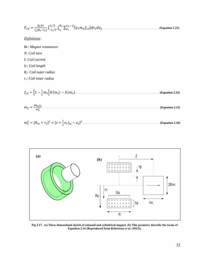
Fig 2.17. (a) Three dimensional sketch of solenoid and cylindrical magnet. (b) This geometry describe the terms of
Equation 2.16 (Reproduced from Robertson et al. (2012)). ........................................................................................ 32
xi
Fig 2.18. Biomolecules such as antibodies, antigens, DNA strand can be attached to the surface of magnetic particles
for biomedical applications (Reproduced from Pamme, (2006)). ................................................................................ 33
Fig 3.1. Block diagram shows the procedures of design electromagnetic platform. ................................................... 37
Fig 3.2. Design of CD for DNA purification (Reproduced from Strohmeier et al. (2013))......................................... 38
Fig 3.3.Magnetic field lines around ring permanent magnet. ...................................................................................... 40
Fig 3.4. Desired locations of maximum magnetic field along “x” direction. ............................................................. 42
Fig 3.5. (a) Simple solenoid with air core (red color indicates maximum magnetic field strength around solenoid).
(b) Electromagnetic platform which constructed from combination of solenoids (4 solenoids). ................................ 43
Fig 3.6. The magnetic field pattern should be homogenous for black points which have specific distance from center
of platform. .................................................................................................................................................................. 44
Fig 3.7. The number of solenoid which is used to create homogeneity inside the electromagnetic platform. ............. 45
Fig 3.8. The directions of forces which act on the magnetic sphere. ........................................................................... 48
Fig 3.9. Dimension of an electromagnetic platform and the distance of magnetic particles from platform. .............. 51
Fig 3.10. Meshing (fine mesh) on electromagnetic platform. ..................................................................................... 55
Fig 4.1. (a) Single solenoid with air core (yellow color shows the maximum magnetic field, red color shows the
minimum magnetic field). (b) The magnetic field pattern along “x” direction of simple solenoid. ........................... 58
Fig 4.2 (a)Solenoid with ring-shaped of aluminum core (red color shows maximum values of magnetic field). (b)
The magnetic field pattern along “x” direction of solenoid with ring-shaped of aluminum core. ............................... 59
Fig 4.3. (a) Combination of solenoids inside the aluminum ring-shaped core (red color shows maximum magnetic
field, black color shows minimum magnetic field). (b) The magnetic field pattern along “x” direction of multiplex
solenoids. ..................................................................................................................................................................... 60
Fig 4.4. concentration of magnetic field around the edge of core. ............................................................................... 61
Fig 4.5. (a) Electromagnetic platform with 4 solenoids. (b) Magnetic field pattern of ring electromagnetic platform
with 4 solenoids. .......................................................................................................................................................... 62
Fig 4.6. (a) Electromagnetic platform with 8 solenoids. (b) Magnetic field pattern of ring electromagnetic platform
with 8 solenoids. .......................................................................................................................................................... 63
Fig 4.7. (a) Electromagnetic platform with 16 solenoids. (b) Magnetic field pattern of ring electromagnetic platform
with 16 solenoids. ........................................................................................................................................................ 64
Fig 4.8. (a) The magnetic field pattern of electromagnetic platform with 4 solenoids (N=4) (b) The magnetic field
pattern of electromagnetic platform with N=8 (c) The magnetic field pattern of electromagnetic platform with N=16.
..................................................................................................................................................................................... 65
Fig 4.9. (a) Relative permeability value of material and ampere turn values of solenoids in 2D space. (b) The
relative permeability of materials, ampere turn values and the results of (grad (B)).B in 3D. .................................... 67

xii
Fig 4.10. The covering of points by polynomial 11. .................................................................................................... 68
Fig 4.11. The covering of points by polynomial 23. .................................................................................................... 69
Fig 4.12. (a) Magnetic particles inside the binding chamber. (b) Magnetic chamber move toward electromagnetic
platform. (c) Coriolis force is applied on magnetic particles to move them toward the opposite direction of rotation
CD. (d) The centrifugal force transfer magnetic particles to the washing chamber (Reproduced from Strohmeier et
al. (2013)). ................................................................................................................................................................... 72
xiii
LIST OF TABLES
Table 2.1. Comparison of four important microfluidic propulsion techniques (Reproduced from Madou et al.
(2006)). .......................................................................................................................................................................... 7
Table 2.2.Classification of different materials. ............................................................................................................ 19
Table 2.3. Required parameters for Equation 8. .......................................................................................................... 26
Table 2.4. The required parameters for Equation 2.10. ................................................................................................ 27
Table 3.1. Dimensions of electromagnetic platform. ................................................................................................... 41
Table 3.2. The information about the magnetic particles and condition of rotating CD (Reproduced from Strohmeier
et al. (2013)). ............................................................................................................................................................... 46
Table 3.3. The required information for calculating surface tension force. (Reproduced form Strohmeier et al.
(2013)). ........................................................................................................................................................................ 47
Table 3.4. Relative permeability and electrical conductivity of materials. .................................................................. 52
Table 3.5. American wire gauge (AWG) to select the size of wire (Reproduced from http://www.powerstream.com).
..................................................................................................................................................................................... 53
Table 4.1. The appropriate values of relative permeability of materials and ampere-turn value. ............................... 71
xiv
LIST OF ABBREVIATIONS
POC Point-of-Care
LOC Lab on a Chip
LOD Lab on a Disc
PCR Polymerase Chain Reaction
MEMs Microelectromechanical Systems
RPM Revolutions per minute
IR Infrared
MRI Magnetic resonance imaging
AWG American wire gauge
1
Chapter 1. INTRODUCTION
1.1 Overview
Medical testing in vitro plays an important role in modern health care. For this reason, the
availability of high sensitive diagnostic tools is a significant issue for all people in the world.
Nowadays, about 70% of medical tests are accomplished in centralized laboratories. The
centralized laboratories should be equipped with sophisticated equipment to perform different
processes of the medical test. In addition, working with this equipment is time-consuming and
needs professional technicians. The remaining 30% of the medical tests are performed as point-
of-care (POC) tests. POC testing can provide immediate and convenient tests for patients. These
types of tests integrate several diagnostic steps which lead to faster and less expensive procedure
compared to centralized testing approaches (Bruls et al., 2009). However, POC devices need
large analytical equipment due to the applied high reagent volume. As a result, microfluidic
technologies have been emerged as powerful enabling tools to improve the related shortcomings
by reduction of reagent volume. Moreover, microfluidic technologies can increase reliability of
POC tests.
Lab-on-a-chip (LOC) is one of the current POC testing systems which utilize
microfluidic diagnostic technologies. There are various techniques for operating microfluidic
functions. These methods are acoustics, pressure, syringe, electrokinetics, electrochemical
bubble generation, and centrifuge (Madou et al., 2006). Among all of these techniques,
centrifuge offers a number of intrinsic advantages such as, removing the need for external pump,
providing wide range of rate flow and handling fluid independent to physicochemical properties
of fluid. In addition, based on physical principle of centrifugal pumping, several centrifuge
fluidic functions (e.g. mixing, valving, metering and switching) can be done in a CD-like plastic
2
substrate. LOC devices which employ centrifugal force to pump liquid between micro chambers
via micro channels are called centrifugal microfluidic platforms or lab-on-a-disc (LOD)
platforms. LOD platforms have successfully demonstrated their capability for high performance
analytical measurement for a wide range of biological assays (e.g. Cell-based assay,
immunoassay, polymerase chain reaction (PCR)). Biological assays need to deliver a great
analytical performance with cost-effective materials. There are various types of magnetic (e.g.
magnetic particles and Ferro fluids) and non-magnetic (diamagnetic objects) materials which can
be applied in biological assays.
Magnetic particles are valuable materials which can be easily manufactured in a wide
range of size from nanometer to micrometer (Aytur, 2007). Different types of biomolecules such
as antigens, antibodies, and DNA strands can be easily attached to these particles due to their
specific surface functionalization. Spherical shape and large surface area are other important
properties of these particles which are desired in mass transferring (Pamme, 2006). The related
advantages of magnetic particles make them appropriate materials for using in LOD systems in a
large number of applications (Strohmeier et al., 2013; Wadle et al., 2012). For example, in cell-
based assays, identification, analysis, capturing, sorting, and selective manipulation of cells can
be simply done by using magnetic particles inside the microfluidic channels (Chen et al., 2011;
Siegrist et al., 2011; Kirby et al., 2012).
Magnetic forces are required for controlling the magnetic particles in LOD platform.
External magnetic field should be applied on microchambers. Magnetic field strength and pattern
can be designed based on the variety types of LOD platforms. In order to obtain desired
magnetic field strength and pattern, many types of permanent magnets and electromagnets have
been manufactured. All of the methods used to control the magnetic particles in the LOD

3
platforms need skillful technicians for setting up the sophisticated electromagnetic arrays or
manual tedious procedures to install permanent magnets. These methods make corresponding
constraints on the automation and miniaturization concepts of LOD platform. By automatic
controlling and manipulating magnetic particles movement from outside of the LOD platform,
under a wide range of centrifugal force, more functions and flexibilities can be achieved in
centrifugal microfluidic systems. For example, automatic controlling the movement of magnetic
particles enables us to trap these particles inside a micro chamber (for binding particles with
biomolecules) in a specified duration of time, and then transport them from one chamber to
another one (for washing the weak binding). These abilities result in performing various assays
on the LOD platform.
The main goal of this project is implementing a multiplex electromagnetic ring that
would be designed exclusively for LOD platforms in order to gain the aforementioned abilities.
This system warrants controlled movements of magnetic particles in microchambers over LOD
platforms.
1.2 Objectives
The objective of this project is to design the electromagnetic platform for controlling
magnetic particles in centrifugal microfluidic platform.
1.3 Scope of this Study
In order to achieve the goal of this study, the following steps have been taken into
account. The corresponding literature has been reviewed to find an appropriate way to calculate
the desired magnetic force for various sizes of magnetic particles under the wide range of
centrifugal force. In addition, several mathematical methods to calculate the magnetic field at

4
any interesting point, above the magnetic ring, have been reviewed. AutoCAD software has been
used to design the centrifugal microfluidic platform. Then, electromagnetic platform has been
designed by means of COMSOL software. Finally the equation of designed electromagnetic
platform has been obtained by employing MATLAB software.
The designed electromagnetic platform consists of 16 solenoids which are located at
circular shape. This electromagnetic platform is located under micro chambers of LOD
platform. By this platform, magnetic particles can be trapped in one chamber in a specified
duration of time and then can be transported from one chamber to another chamber
automatically.
1.4 Outline of Thesis
This thesis consists of five chapters. In first Chapter, it discussed the objective, scope and
summary of this project; while the Chapter 2 will be discussed more on literature review of
platforms that have been simulated. It discussed about centrifugal microfluidic platform and
magnetic theory. In Chapter 3 the discussion will be on the mathematical calculation, design and
simulation of the electromagnetic platform. Moreover, the results and interpretations are shown
in Chapter 4. The Chapter 5 is conclusion and recommendation for the overall project.

5
Chapter 2. LITERATURE REVIEW
This section is divided into three subsections. At the first section, the details regarding to
Centrifugal microfluidic platform are provided. This section comprises; background, theoretical
principle, centrifugal microfluidic functions, analytical measurement techniques and finally
applications of this platform. At the second section, magnetic theory is reviewed. This section
deals with the magnetic properties of different types of materials. Then, different types of
magnets (ring permanent magnet and temporary magnet) are discussed in this section. At the
third section, the combination of microfluidics and magnetism are reviewed.
2.1 Centrifugal Microfluidic Platform
Centrifugal microfluidic platforms which are known as lab-on-a-disk (LOD) or compact
disk (CD) microfluidics are a powerful solution for medical and clinical diagnostics applications.
The principal of the technique is that it exploits centrifugal force to drive liquids inside
microfluidic system for properly mixing the samples and reagents and to perform diagnostic
assays. So, each steps of the process will be carried out automatically by controlling the rotation
speed of the CD as well as the liquid flow (Lai et al., 2004). Based on physical principle of
centrifugal pumping, several centrifuge fluidic functions can be implemented on LOD platform.
In addition, various analytical measurement techniques can be utilized for this platform. The
combination of centrifuge fluidic functions and analytical measurement techniques make a
centrifugal microfluidic platform a great solution for diagnostics applications such as,
immunoassay and polymerase chain reaction (PCR) (Madou et al., 2006).

6
2.1.1 Background
The use of microfluidic technologies for carrying out miniaturization on the analytical
equipment through the reduction in reagent volumes, improves the shortcomings related to the
use of large and expensive instrumentations. In addition, microfluidic technologies simplify the
job of analytical assays by full incorporation of analytical procedures in flowing systems. These
technologies can be performed in low-cost and disposable instruments to prevent sample
contamination. Furthermore, it has a potential to scale the important instrument process such as,
cooling, heating, chromatographic and electrophoretic separation in micro domain (Madou et al.,
2006). In order to increase functionality of microfluidic systems to perform analytical assays,
microelectromechanical systems (MEMs) are employed. The combination of these two
technologies allows the integration of different types of functions (e.g. electrical and
electrochemical functions) into chips for different procedures of analytical assays such as,
sensing the parameters of assay and biomolecular detection (Verpoorte et al., 2003). Lab-on-a-
chip (LOC) is a device that utilizes the integration of these two technologies. Single or multiple
laboratory functions are performed on a chip by handling small volume of fluid inside
interconnected micro channels. Several technologies for handling fluid inside the micro channel
exist, including acoustics, pressure, syringe, electrokinetics, electrochemical bubble generation
and centrifuge. Table 2.1 displays the comparison of four important microfluidic propulsion
techniques (Madou et al., 2006).
7
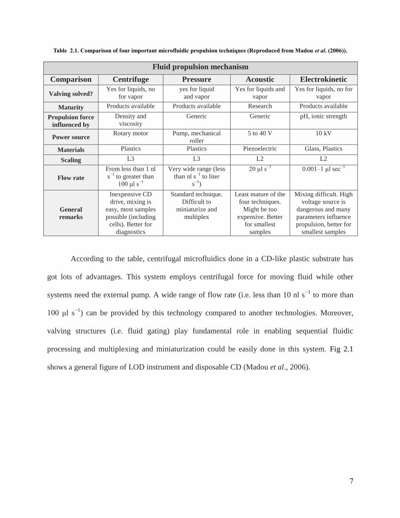
Table 2.1. Comparison of four important microfluidic propulsion techniques (Reproduced from Madou et al. (2006)).
According to the table, centrifugal microfluidics done in a CD-like plastic substrate has
got lots of advantages. This system employs centrifugal force for moving fluid while other
systems need the external pump. A wide range of flow rate (i.e. less than 10 nl s−1
to more than
100 μl s−1
) can be provided by this technology compared to another technologies. Moreover,
valving structures (i.e. fluid gating) play fundamental role in enabling sequential fluidic
processing and multiplexing and miniaturization could be easily done in this system. Fig 2.1
shows a general figure of LOD instrument and disposable CD (Madou et al., 2006).
Fluid propulsion mechanism
Comparison Centrifuge Pressure Acoustic Electrokinetic
Valving solved? Yes for liquids, no
for vapor
yes for liquid
and vapor
Yes for liquids and
vapor
Yes for liquids, no for
vapor
Maturity Products available Products available Research Products available
Propulsion force
influenced by
Density and
viscosity
Generic Generic pH, ionic strength
Power source Rotary motor Pump, mechanical
roller
5 to 40 V 10 kV
Materials Plastics Plastics Piezoelectric Glass, Plastics
Scaling L3 L3 L2 L2
Flow rate
From less than 1 nl
s−1
to greater than
100 μl s−1
Very wide range (less
than nl s−1
to liter
s−1
)
20 μl s−1
0.001–1 μl sec−1
General
remarks
Inexpensive CD
drive, mixing is
easy, most samples
possible (including
cells). Better for
diagnostics
Standard technique.
Difficult to
miniaturize and
multiplex
Least mature of the
four techniques.
Might be too
expensive. Better
for smallest
samples
Mixing difficult. High
voltage source is
dangerous and many
parameters influence
propulsion, better for
smallest samples

8
2.1.2 Theoretical Principle
The theoretical principle of the LOD platform contains the principle of fluid rate as well
as the principle of basic forces which are applied on fluid or on suspended particles. Rotation
rate, geometry and location of channels and reservoirs, as well as fluid properties determine the
CD fluid propulsion which is occurred via centrifugally induced pressure. The average velocity
of the liquid (u) can be found by Equation 2.1(Madou et al., 2006).
………………………………………………………………………………………………………………………………………..……………..……(Equation 2.1)
Definitions:
Dh: hydraulic diameter of the channel
L: the length of the liquid in the capillary channel
r-: the average distance of the liquid in the channels to the center of the CD
w: angular speed of the CD
μ: radial extent of the fluid
Fig 2.1.General figure of LOD instrument and disposable CD (Reproduced from Madou
et al. (2006)).
9
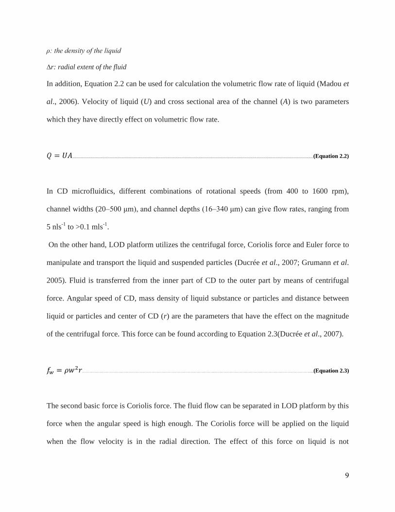
ρ: the density of the liquid
∆r: radial extent of the fluid
In addition, Equation 2.2 can be used for calculation the volumetric flow rate of liquid (Madou et
al., 2006). Velocity of liquid (U) and cross sectional area of the channel (A) is two parameters
which they have directly effect on volumetric flow rate.
..........................................................................................................................................................................................................................................................................................................(Equation 2.2)
In CD microfluidics, different combinations of rotational speeds (from 400 to 1600 rpm),
channel widths (20–500 μm), and channel depths (16–340 μm) can give flow rates, ranging from
5 nls-1
to >0.1 mls-1
.
On the other hand, LOD platform utilizes the centrifugal force, Coriolis force and Euler force to
manipulate and transport the liquid and suspended particles (Ducrée et al., 2007; Grumann et al.
2005). Fluid is transferred from the inner part of CD to the outer part by means of centrifugal
force. Angular speed of CD, mass density of liquid substance or particles and distance between
liquid or particles and center of CD (r) are the parameters that have the effect on the magnitude
of the centrifugal force. This force can be found according to Equation 2.3(Ducrée et al., 2007).
………………………………………………….………………………………………………………...……………………………………………………………………………......(Equation 2.3)
The second basic force is Coriolis force. The fluid flow can be separated in LOD platform by this
force when the angular speed is high enough. The Coriolis force will be applied on the liquid
when the flow velocity is in the radial direction. The effect of this force on liquid is not
10
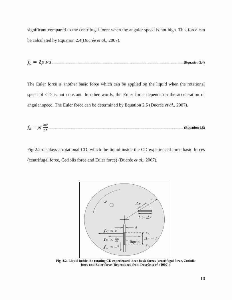
significant compared to the centrifugal force when the angular speed is not high. This force can
be calculated by Equation 2.4(Ducrée et al., 2007).
……………………………………….………………………………………………………...……………………………………………………………………….……………..(Equation 2.4)
The Euler force is another basic force which can be applied on the liquid when the rotational
speed of CD is not constant. In other words, the Euler force depends on the acceleration of
angular speed. The Euler force can be determined by Equation 2.5 (Ducrée et al., 2007).
……………………………………….………………………………………………………...……………………………………………………………………….……………….. (Equation 2.5)
Fig 2.2 displays a rotational CD, which the liquid inside the CD experienced three basic forces
(centrifugal force, Coriolis force and Euler force) (Ducrée et al., 2007).
Fig 2.2. Liquid inside the rotating CD experienced three basic forces (centrifugal force, Coriolis
force and Euler force (Reproduced from Ducrée et al. (2007)).
11
2.1.3 Functions
There are various types of functions in a centrifugal microfluidic structure such as,
mixing, valving, metering and switching.
2.1.3.1 Valving
Controlling of fluid flow consists of ability to start and stop the fluid flow. Valving
structures play fundamental role in flow control and enabling sequential fluidic processing. The
valve holds until spin velocities, measured in rotations per minute (RPM), are increased above a
critical threshold, known as the burst frequency. This frequency can be found according to
Equation 2.6 where θ is contact angle and γ is surface tension of fluid (Lai et al., 2004).
……………………………………….………………………………………………………...………………………………….………………………….. (Equation 2.6)
The microfluidic applications are multiplexed and, as such, several valving components
must work simultaneously. In addition, compatibility, long-term stability, prevention of cross-
contamination and actuation in accordance with the design paradigms of the instrument are
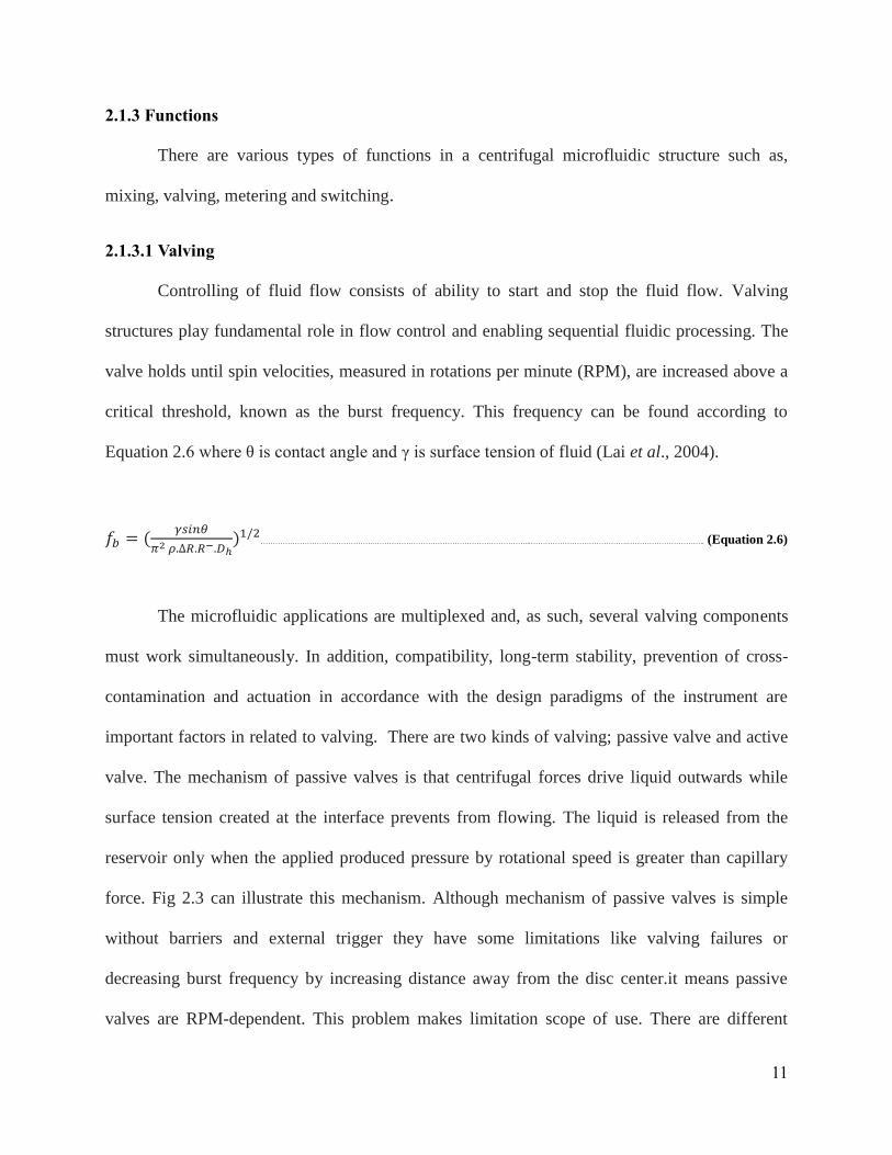
important factors in related to valving. There are two kinds of valving; passive valve and active
valve. The mechanism of passive valves is that centrifugal forces drive liquid outwards while
surface tension created at the interface prevents from flowing. The liquid is released from the
reservoir only when the applied produced pressure by rotational speed is greater than capillary
force. Fig 2.3 can illustrate this mechanism. Although mechanism of passive valves is simple
without barriers and external trigger they have some limitations like valving failures or
decreasing burst frequency by increasing distance away from the disc center.it means passive
valves are RPM-dependent. This problem makes limitation scope of use. There are different
12
kinds of passive valves such as hydrophobic valves, pneumatic passive valves, siphon valves,
etc. The active valving was introduced to overcome the limitations of passive valving and also
for expanded use. The mechanism of active valve is that act as programmable control of fluidic
flow elements where a physical gating material is changed or removed by an external actuation
source. Depend on type of active valve gating material and actuation source will be changed.
There are many types of active valves such as using wax and focused infrared (IR) lamp; using
Ferro wax and laser diode; heat absorbing printer toner with Laser diodes as gating and actuation
source respectively. Thus active valve is not RPM-dependent and can solve some problems in
passive valving (Madou et al., 2001; Yusoff et al., 2009).
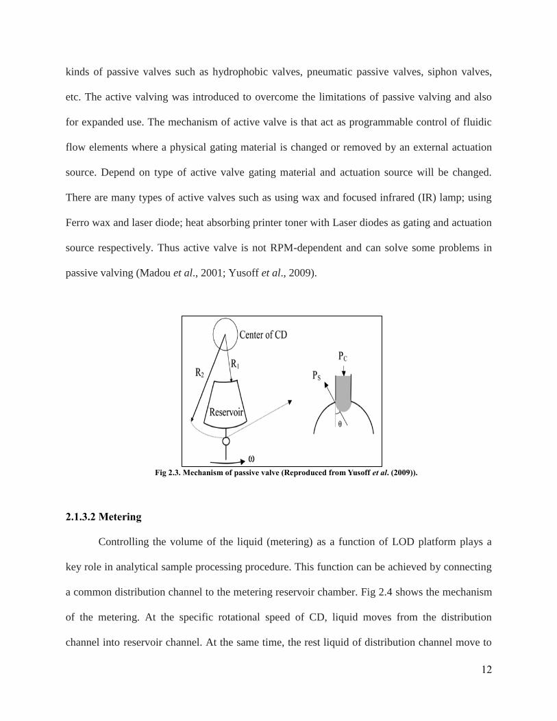
2.1.3.2 Metering
Controlling the volume of the liquid (metering) as a function of LOD platform plays a
key role in analytical sample processing procedure. This function can be achieved by connecting
a common distribution channel to the metering reservoir chamber. Fig 2.4 shows the mechanism
of the metering. At the specific rotational speed of CD, liquid moves from the distribution
channel into reservoir channel. At the same time, the rest liquid of distribution channel move to
Fig 2.3. Mechanism of passive valve (Reproduced from Yusoff et al. (2009)).
13
the waste channel. When the rotational speed of CD increases the liquid will transfer from
reservoir channel into the next channel. The volume of the liquid can be determined by
measuring the volume of the reservoir channel (Madou et al., 2006).
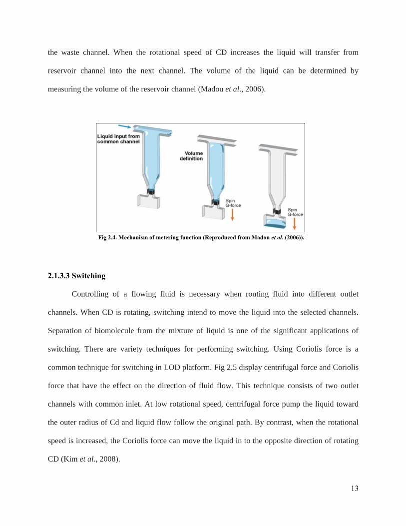
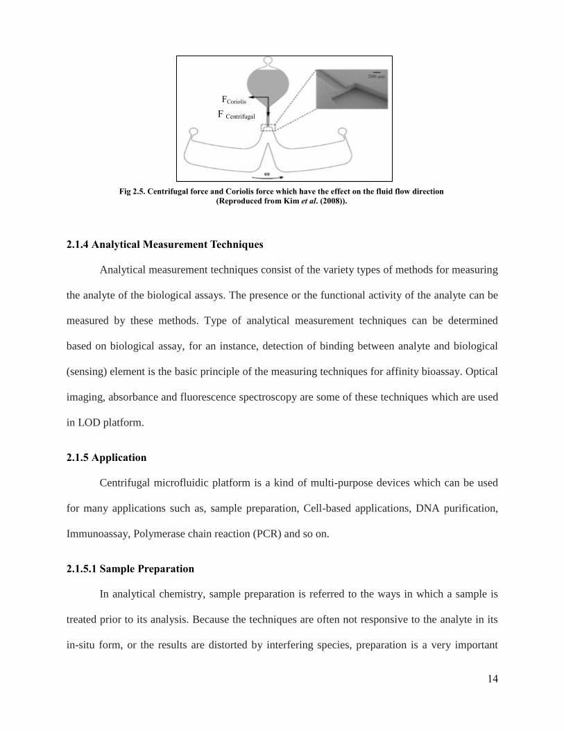
2.1.3.3 Switching
Controlling of a flowing fluid is necessary when routing fluid into different outlet
channels. When CD is rotating, switching intend to move the liquid into the selected channels.
Separation of biomolecule from the mixture of liquid is one of the significant applications of
switching. There are variety techniques for performing switching. Using Coriolis force is a
common technique for switching in LOD platform. Fig 2.5 display centrifugal force and Coriolis
force that have the effect on the direction of fluid flow. This technique consists of two outlet
channels with common inlet. At low rotational speed, centrifugal force pump the liquid toward
the outer radius of Cd and liquid flow follow the original path. By contrast, when the rotational
speed is increased, the Coriolis force can move the liquid in to the opposite direction of rotating
CD (Kim et al., 2008).
Fig 2.4. Mechanism of metering function (Reproduced from Madou et al. (2006)).
14
2.1.4 Analytical Measurement Techniques
Analytical measurement techniques consist of the variety types of methods for measuring
the analyte of the biological assays. The presence or the functional activity of the analyte can be
measured by these methods. Type of analytical measurement techniques can be determined
based on biological assay, for an instance, detection of binding between analyte and biological
(sensing) element is the basic principle of the measuring techniques for affinity bioassay. Optical
imaging, absorbance and fluorescence spectroscopy are some of these techniques which are used
in LOD platform.
2.1.5 Application
Centrifugal microfluidic platform is a kind of multi-purpose devices which can be used
for many applications such as, sample preparation, Cell-based applications, DNA purification,
Immunoassay, Polymerase chain reaction (PCR) and so on.
2.1.5.1 Sample Preparation
In analytical chemistry, sample preparation is referred to the ways in which a sample is
treated prior to its analysis. Because the techniques are often not responsive to the analyte in its
in-situ form, or the results are distorted by interfering species, preparation is a very important
FCoriolis
F Centrifugal
Fig 2.5. Centrifugal force and Coriolis force which have the effect on the fluid flow direction
(Reproduced from Kim et al. (2008)).

15
step in most analytical techniques. Manual sample preparation is relatively tiresome and time
consuming, and can introduce errors common to multi-step pipetting. Developing LOD platform
for automation of sample preparation has shown a lot of promises in this field (Glasgow et al.,
2003).
2.1.5.2 Cell-Based Applications
Cell separation, purification, sorting and manipulating are significant processes for
clinical diagnostic applications. In addition, capturing of cell, cell counting and assaying play an
important role for research usages. Cell separation and purification are primary process for cell
analysis. The main objective of this process is separating the target cells from the surrounding
medium. Separation of target cell from the medium can be done by different methods which
depend on the characteristics of cell such as, dielectric features, size, density and morphological
characteristics. In order to manipulate of cell, complex, expensive and sophisticated equipment
are required. Therefore, both clinical diagnostic and research applications need to low-cost and
portable systems. LOD platforms have effectively established their intrinsic advantages for Cell
handling and cell identification applications (Burger et al., 2012; Chen et al., 2011).
2.1.5.3 DNA Purification
DNA purification is a process of isolation DNA from the sample. Several chemical and
physical methods can be used for DNA purification. In general, isolation DNA from cellular
components can be done by sequential stages including, disruption, lysis, removing proteins,
removing contaminants and recovery of DNA. All of these sequential stages can be perfumed by
professional techniques which are used in LOD platforms (Strohmeier et al., 2013; Wadle et al.,
2012).

16
2.1.5.4 Immunoassay
An immunoassay is a biochemical test that measures the presence or concentration of a
substance in solutions containing a complex mixture of substances. Immunoassay methods are
usually used to assay analyte in biological liquids such as serum, saliva or urine. The exceptional
ability of an antibody to bind with high specificity to one or a very limited group of molecules is
the basic for this kind of assays. In addition to that, the other key feature of all immunoassays is
a means to produce a measurable signal in response to a specific binding. Historically this was
accomplished by measuring a change in some physical characteristic such as light scattering or
changes in refractive index. The automation of immunoassays on microfluidic platforms is
challenging because of the high number of fluidic processes and liquid reagents involved. CD
platform is of interest for multiple parallel immunoassays because it can provide simultaneous
and identical flow rates, incubation times, mixing dynamics and detection (Lai et al., 2004).
2.1.5.5 Polymerase chain reaction (PCR)
The polymerase chain reaction (PCR), an important process for nucleic acid analysis, is a
scientific technique in molecular biology to amplify a single or few copies of a piece of DNA
across several orders of magnitude, generating thousands to millions of copies of a particular
DNA sequence. This process needs substantial sample preparation that, unless automated, is
laboured extensive. Current bench-top PCR systems can take on the order of hours to complete a
set of PCR cycles. As a primary example, combined sample preparation with PCR on the CD
was reported by Kellogg et al. (Kido et al., 2007) They demonstrated sample preparation and
PCR amplification for two types of samples, whole blood and Escherichia coli, on the CD
platform and shown that the results are as good as the conventional methods.
17
2.2 Magnetism
2.2.1 Magnetic Theory
There are four main magnetic vectors namely, magnetic field (H), magnetization (M),
magnetic flux density (B) and magnetic force (F). All of these vectors can be specified by both
strength and direction.
Magnetic fields (H) are produced by magnetic materials and electric currents. Atomic
structure of materials consists of positive charges (i.e. nucleus) and negative charges (i.e.
electrons). Spinning of atomic components comprising, rotating electrons around nucleus and
rotating nucleus and electrons relative to their axes is the reason of creation magnetic dipoles.
The magnetic dipole moment of rotating electrons around nucleus is more significant than
rotation electrons or nucleus around their axes. Therefore, the presence of moving charges in
magnetic materials (i.e. spinning of electrons around nuclei) and electric currents (i.e. flowing of
electrons along a wire) is the main reason of magnetic field generation. There are two types of
magnetic field including, static magnetic field and time-varying magnetic field. Static magnetic
fields are generated by permanent magnets and steady currents whereas time-varying magnetic
fields are produced by time-varying currents. The unit of magnetic field vector is Ampere per
meter (A/m).
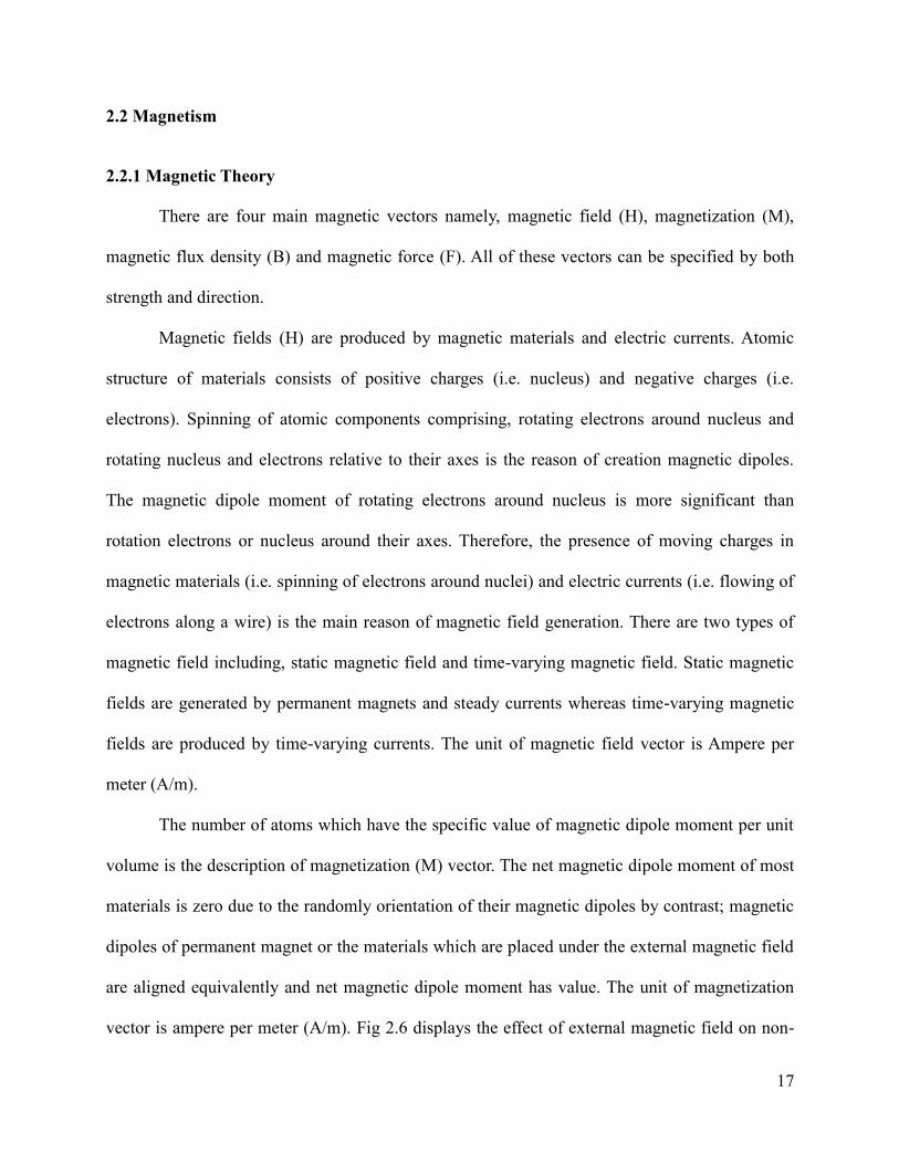
The number of atoms which have the specific value of magnetic dipole moment per unit
volume is the description of magnetization (M) vector. The net magnetic dipole moment of most
materials is zero due to the randomly orientation of their magnetic dipoles by contrast; magnetic
dipoles of permanent magnet or the materials which are placed under the external magnetic field
are aligned equivalently and net magnetic dipole moment has value. The unit of magnetization
vector is ampere per meter (A/m). Fig 2.6 displays the effect of external magnetic field on non-
18
magnetized material (Cheng, 1989).
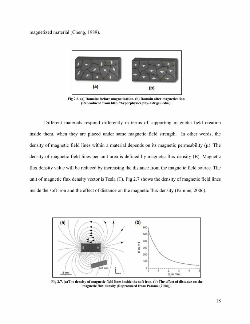
Different materials respond differently in terms of supporting magnetic field creation
inside them, when they are placed under same magnetic field strength. In other words, the
density of magnetic field lines within a material depends on its magnetic permeability (µ). The
density of magnetic field lines per unit area is defined by magnetic flux density (B). Magnetic
flux density value will be reduced by increasing the distance from the magnetic field source. The
unit of magnetic flux density vector is Tesla (T). Fig 2.7 shows the density of magnetic field lines
inside the soft iron and the effect of distance on the magnetic flux density (Pamme, 2006).
Fig 2.6. (a) Domains before magnetization. (b) Domain after magnetization
(Reproduced from http://hyperphysics.phy-astr.gsu.edu/).
Fig 2.7. (a)The density of magnetic field lines inside the soft iron. (b) The effect of distance on the
magnetic flux density (Reproduced from Pamme (2006)).
19
Magnets apply magnetic forces (F) on each other as a result of interactions between
magnetic dipoles of first magnet and magnetic dipoles of second magnet. Attractive and
repulsive magnetic force can be determined by recognizing the all magnetic dipoles of the first
and second magnets. The unit of magnetic force vector is Newton (N).
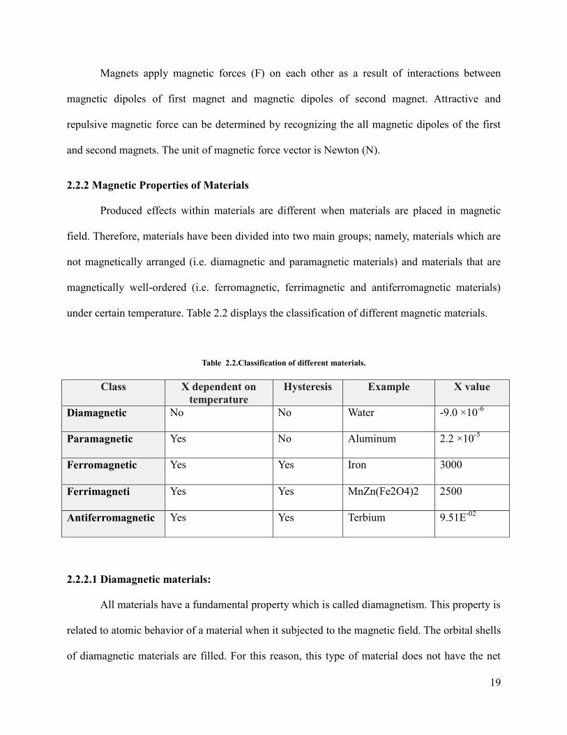
2.2.2 Magnetic Properties of Materials
Produced effects within materials are different when materials are placed in magnetic
field. Therefore, materials have been divided into two main groups; namely, materials which are
not magnetically arranged (i.e. diamagnetic and paramagnetic materials) and materials that are
magnetically well-ordered (i.e. ferromagnetic, ferrimagnetic and antiferromagnetic materials)
under certain temperature. Table 2.2 displays the classification of different magnetic materials.
Table 2.2.Classification of different materials.
2.2.2.1 Diamagnetic materials:
All materials have a fundamental property which is called diamagnetism. This property is
related to atomic behavior of a material when it subjected to the magnetic field. The orbital shells
of diamagnetic materials are filled. For this reason, this type of material does not have the net
Class Χ dependent on
temperature
Hysteresis Example Χ value
Diamagnetic No No Water -9.0 ×10⁻⁶
Paramagnetic Yes No Aluminum 2.2 ×10⁻⁵
Ferromagnetic Yes Yes Iron 3000
Ferrimagneti Yes Yes MnZn(Fe2O4)2 2500
Antiferromagnetic Yes Yes Terbium 9.51E-02
20
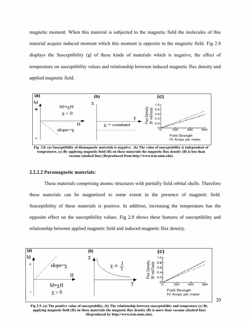
magnetic moment. When this material is subjected to the magnetic field the molecules of this
material acquire induced moment which this moment is opposite to the magnetic field. Fig 2.8
displays the Susceptibility (χ) of these kinds of materials which is negative, the effect of
temperature on susceptibility values and relationship between induced magnetic flux density and
applied magnetic field.
2.2.2.2 Paramagnetic materials:
These materials comprising atomic structures with partially field orbital shells. Therefore
these materials can be magnetized to some extent in the presence of magnetic field.
Susceptibility of these materials is positive. In addition, increasing the temperature has the
opposite effect on the susceptibility values. Fig 2.9 shows these features of susceptibility and
relationship between applied magnetic field and induced magnetic flux density.
Fig 2.9. (a) The positive value of susceptability. (b) The relationship between susceptability and temprature (c) By
applying magnetic field (H) on these materials the magnetic flux density (B) is more than vacume (dashed line)
(Reproduced by http://www.irm.umn.edu).
Fig 2.8. (a) Susceptibility of diamagnetic materials is negative. (b) The value of susceptability is independent of
tempratures. (c) By applying magnetic field (H) on these materials the magnetic flux density (B) is less than
vacume (dashed line) (Reproduced from http://www.irm.umn.edu).

21
2.2.2.3 Ferromagnetic materials:
These materials can be magnetized more strongly than paramagnetic materials due to the
strong interactions of atomic moments when the magnetic field is applied. The magnetic moment
of atoms in such materials have tendency to become parallel (Fig 2.10.(a)). By applying the
magnetic field to this material, the magnetic flux density will be in the range of Tesla and the BH
curve (Fig 2.10.(b)) will not be linear while both diamagnetic and paramagnetic materials have
magnetic flux density in the range of milliTesla and their BH curves are linear.
Remanence and coercivity are two another features of ferromagnetic materials which
make them distinct from paramagnetic and diamagnetic materials. Magnetic flux density of these
materials is zero in the absence of external magnetic field. By applying magnetic field on the
material, magnetic flux density will be appearing. Hysteresis loop is a curve which can be used
for learning about the properties of some materials (Fig 2.11). In this curve, increasing magnetic
field strength is the cause of growing magnetic flux density until the material reach to the
Fig 2.10. Ferromagnetic material. (b) BH curve of ferromagnetic materials. (Reproduced
by http://www.irm.umn.edu).
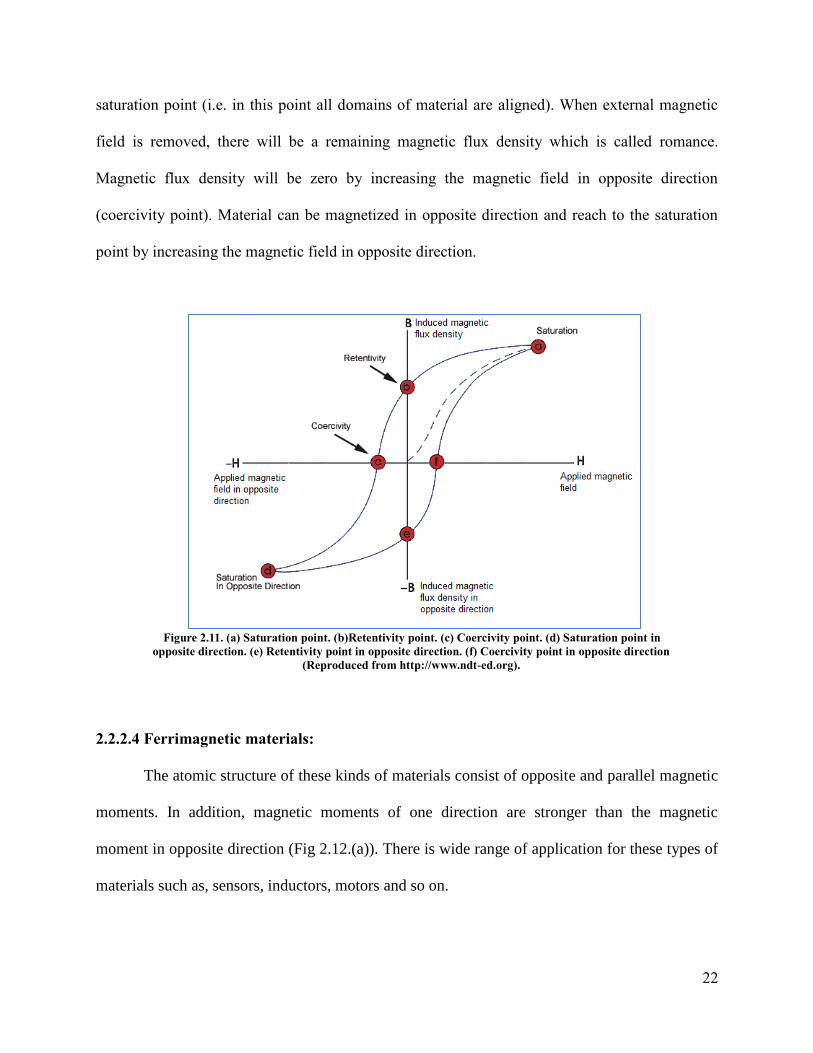
22
saturation point (i.e. in this point all domains of material are aligned). When external magnetic
field is removed, there will be a remaining magnetic flux density which is called romance.
Magnetic flux density will be zero by increasing the magnetic field in opposite direction
(coercivity point). Material can be magnetized in opposite direction and reach to the saturation
point by increasing the magnetic field in opposite direction.
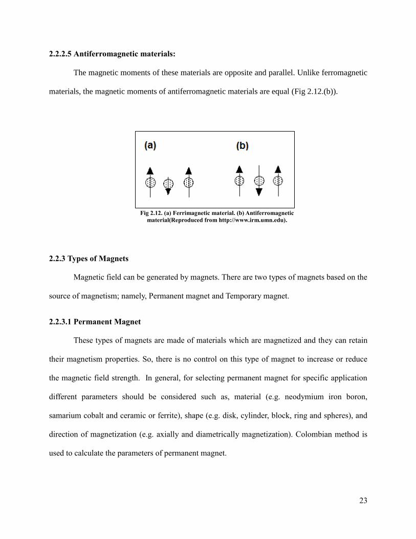
2.2.2.4 Ferrimagnetic materials:
The atomic structure of these kinds of materials consist of opposite and parallel magnetic
moments. In addition, magnetic moments of one direction are stronger than the magnetic
moment in opposite direction (Fig 2.12.(a)). There is wide range of application for these types of
materials such as, sensors, inductors, motors and so on.
Figure 2.11. (a) Saturation point. (b)Retentivity point. (c) Coercivity point. (d) Saturation point in
opposite direction. (e) Retentivity point in opposite direction. (f) Coercivity point in opposite direction
(Reproduced from http://www.ndt-ed.org).
23
2.2.2.5 Antiferromagnetic materials:
The magnetic moments of these materials are opposite and parallel. Unlike ferromagnetic
materials, the magnetic moments of antiferromagnetic materials are equal (Fig 2.12.(b)).
2.2.3 Types of Magnets
Magnetic field can be generated by magnets. There are two types of magnets based on the
source of magnetism; namely, Permanent magnet and Temporary magnet.
2.2.3.1 Permanent Magnet
These types of magnets are made of materials which are magnetized and they can retain
their magnetism properties. So, there is no control on this type of magnet to increase or reduce
the magnetic field strength. In general, for selecting permanent magnet for specific application
different parameters should be considered such as, material (e.g. neodymium iron boron,
samarium cobalt and ceramic or ferrite), shape (e.g. disk, cylinder, block, ring and spheres), and
direction of magnetization (e.g. axially and diametrically magnetization). Colombian method is
used to calculate the parameters of permanent magnet.
Fig 2.12. (a) Ferrimagnetic material. (b) Antiferromagnetic
material(Reproduced from http://www.irm.umn.edu).

24
2.2.3.1.1 Ring Magnet
There is wide range of applications for axially and radially magnetized ring permanent
magnet for instance, sensors and actuators, magnetic bearing and magnetic separating devices.
Therefore, calculation the magnetic parameters (e.g. magnetic field, magnetic flux density and
magnetic force) of such structures are very significant. In order to calculate the magnetic force of
ring at any point of interest, the exact value of magnetic field at that point is required. So far
variety analytical and numerical methods have been used for calculation the magnetic field
strength around a ring magnet which is axially or radially magnetized (Ravaud et al., 1989;
Babic et al., 2008; Ravaud et al., 2009). Fig 2.13 shows axially and radially magnetized ring.
This study deals with axially magnetized ring permanent magnet.
Cylindrical coordinate is used in order to calculate three components of magnetic field
(i.e. Hr, Hθ, Hz) around permanent ring magnet. Coulombian method (Equation 2.7) is one of the
analytical methods for calculation the magnetic parameters of permanent magnet. Fig 2.14
displays the parameters which were used in this method.
�⃗⃗� , 𝜃, 𝑧 �⃗⃗� + , 𝜃, 𝑧 + �⃗⃗� , 𝜃, 𝑧 …………………………………………………………………………………………………………..……..(Equation 2.7)
Fig 2.13. (a) Axially magnetized ring. (b) Radially magnetized ring
(Reproduced from http://www.kjmagnetics.com)

25
�⃗⃗� + , 𝜃, 𝑧 𝜎
4 𝜇0∫ ∫
𝑃1+𝑀
|𝑃1+𝑀|3
𝑟1=𝑟𝑜𝑢𝑡
𝑟1=𝑟𝑖𝑛 𝑑 𝑑𝜃
=
=0………………………………………………………………………………………….(Equation 2.8)
𝑃 + �⃗⃗� − 𝑐𝑜𝑠 𝜃 𝑖𝑟⃗⃗ − 𝑠𝑖𝑛 𝜃 𝑖 ⃗⃗ ⃗ + 𝑧 − ℎ 𝑖𝑘⃗⃗⃗ …………………………………………………………………………………(Equation 2.9)
�⃗⃗� , 𝜃, 𝑧 𝜎
4 𝜇0∫ ∫
𝑃1 𝑀
|𝑃1 𝑀|3
𝑟1=𝑟𝑜𝑢𝑡
𝑟1=𝑟𝑖𝑛 𝑑 𝑑𝜃
=
=0……………………………………………………………………………………... (Equation 2.10)
𝑃 − �⃗⃗� − cos 𝜃 𝑖𝑟⃗⃗ − sin 𝜃 𝑖 ⃗⃗ ⃗ + 𝑧 + ℎ 𝑖𝑘⃗⃗⃗ …………………………………………………………………………...….(Equation 2.11)
Definitions:
σ: Surface magnetic pole density (Tesla)
μ0: Magnetic permeability of vacuum (Henry per meter)
Coulombian method was employed by (Ravaud et al., 1989) for calculating three components of
magnetic field around ring but this method was not successful for all points (i.e. just for regular
points) around the ring. The equations of this method were modified by (Babic et al., 2008) in
order to calculate magnetic field components for any point of interest (i.e. regular and singular
points) around ring permanent magnet. Radial component (r) of magnetic field can be calculated
by Equation 2.12. Table 2.3 shows the parameters were used in this equation.
Fig 2.14. Axially magnetized ring permanent magnet at cylindrical coordinate (Reproduced
from Babic et al. (2008)).
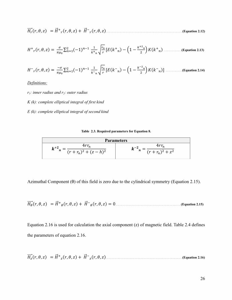
26
𝐻𝑟⃗⃗ ⃗⃗ , 𝜃, 𝑧 �⃗⃗� +𝑟 , 𝜃, 𝑧 + �⃗⃗� 𝑟 , 𝜃, 𝑧 ………………………………………………………………………………………………………….(Equation 2.12)
𝐻+𝑟 , 𝜃, 𝑧
𝜎
𝜇0∑ −1
=
𝑘+𝑛√
𝑟𝑛
𝑟[𝐸 𝑘+
− (1 −𝑘+
𝑛
)𝐾 𝑘+
……………………….(Equation 2.13)
𝐻 𝑟 , 𝜃, 𝑧
𝜎
𝜇0∑ −1
=
𝑘 𝑛√
𝑟𝑛
𝑟[𝐸 𝑘
− (1 −𝑘
𝑛
)𝐾 𝑘
] ……………..……….(Equation 2.14)
Definitions:
r1: inner radius and r2: outer radius
K (k): complete elliptical integral of first kind
E (k): complete elliptical integral of second kind
Table 2.3. Required parameters for Equation 8.
Azimuthal Component (θ) of this field is zero due to the cylindrical symmetry (Equation 2.15).
𝐻 ⃗⃗⃗⃗ ⃗ , 𝜃, 𝑧 �⃗⃗� + , 𝜃, 𝑧 + �⃗⃗� , 𝜃, 𝑧 0…………………………………………………………………………………..………(Equation 2.15)
Equation 2.16 is used for calculation the axial component (z) of magnetic field. Table 2.4 defines
the parameters of equation 2.16.
𝐻𝑧⃗⃗ ⃗⃗ , 𝜃, 𝑧 �⃗⃗� +𝑧 , 𝜃, 𝑧 + �⃗⃗� 𝑧 , 𝜃, 𝑧 ………………………………………………………………………………………………..…..…….(Equation 2.16)
Parameters
𝒌+𝟐𝒏
4 + + 𝑧 − ℎ
𝒌 𝟐𝒏
4 + + 𝑧
27
𝐻+𝑧 , 𝜃, 𝑧
𝜎
𝜇0∑ −1
= {𝑘+
𝑛 𝑧 √𝑟 + 𝑧
√𝑟𝑟𝑛(√𝑟 + 𝑧 +𝑟)𝐾 𝑘+
+
𝑠𝑖𝑔𝑛 𝑧 −
ℎ 𝑠𝑖𝑔𝑛 (√ + 𝑧 − ℎ − ) [1 − Λ0 𝜃+ , 𝑘
+ ] +
𝑠𝑖𝑔𝑛 𝑧 − ℎ [1 −
Λ0 𝜃+ , 𝑘
+ ]} …………………………………………………………………………………………………………………………………………………………………..……..(Equation 2.17)
𝐻 𝑧 , 𝜃, 𝑧
𝜎
𝜇0∑ −1
= {𝑘
𝑛𝑧√𝑟 +𝑧
√𝑟𝑟𝑛(√𝑟 +𝑧 +𝑟)𝐾 𝑘
+
𝑠𝑖𝑔𝑛 𝑧 𝑠𝑖𝑔𝑛(√ + 𝑧 −
)[1 − Λ0 𝜃 , 𝑘
] +
𝑠𝑖𝑔𝑛 𝑧 [1 − Λ0 𝜃
, 𝑘
]}………………………………………………………………(Equation 2.18)
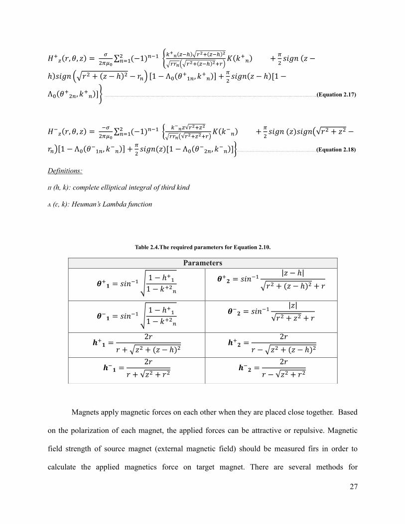
Definitions:
ᴨ (h, k): complete elliptical integral of third kind
ʌ (ɛ, k): Heuman’s Lambda function
Table 2.4.The required parameters for Equation 2.10.
Magnets apply magnetic forces on each other when they are placed close together. Based
on the polarization of each magnet, the applied forces can be attractive or repulsive. Magnetic
field strength of source magnet (external magnetic field) should be measured firs in order to
calculate the applied magnetics force on target magnet. There are several methods for
Parameters
𝜽+𝟏 𝑠𝑖𝑛 √
1 − ℎ+
1 − 𝑘+
𝜽+𝟐 𝑠𝑖𝑛
|𝑧 − ℎ|
√ + 𝑧 − ℎ +
𝜽 𝟏 𝑠𝑖𝑛 √
1 − ℎ+
1 − 𝑘+
𝜽 𝟐 𝑠𝑖𝑛
|𝑧|
√ + 𝑧 +
𝒉+𝟏
+ √𝑧 + 𝑧 − ℎ 𝒉+
𝟐
− √𝑧 + 𝑧 − ℎ
𝒉 𝟏
+ √𝑧 + 𝒉
𝟐
− √𝑧 +
28
computation the magnetic force comprising, Surface integration (Maxwell’s Stress Tensor
approach), volume integration (Virtual Work Method) and finally surface and volume integration
(Equivalent Source Method) (Delfino et al., 2001). Among all of these methods, equivalent
source method has got a lot of interests. This method is based on replacing of permanent magnet
with surface and volume distribution of currents, dipoles or magnetic charges. Then, magnetic
force of each element is calculated. The total force is the result of summation the calculated
magnetic force of each element. The Equations 2.19, 2.20 and 2.21 represent the magnetic force
which is applied on target magnet by replacing magnets with surface and volume distribution of
currents, dipole and magnetic charges respectively.
𝐹 ∫ 𝐽𝑚𝑣 × 𝐵𝑒𝑥 𝑑𝛺 + ∮ 𝐽𝑚 × 𝐵𝑒𝑥 𝑑𝛺
𝛴
𝛺…………………………………………………………………………………………..………………….(Equation 2.19)
𝐹 ∫ 𝑀 𝛻𝐻𝑑𝛺 +
𝜇0∮ 𝑀 𝑛 𝑑𝛺
𝛴
𝛺 ………………………………………………………………………………………..…………………………….. (Equation 2.20)
𝐹 ∫ 𝑚𝐻𝑒𝑥 𝑑𝛺 + ∮ 𝜎𝑚𝐻𝑒𝑥 𝑑𝑆
𝛴
𝛺………………………………………………………………………………………..………………………………………(Equation 2.21)
Definitions:
Jmv: Volume density of current 𝐽𝑚𝑣 1 0∇ × 𝑀
Jms: Surface density of current 𝐽𝑚 1 0𝑀 × 𝑛
ρm: Volume density of magnetic charges 𝑚 −∇ 𝑀
σm: Surface density of magnetic charges 𝜎𝑚 𝑀 𝑛
Bext: External magnetic flux density
Hext: External magnetic field
M: Magnetization
Ω: Volume occupied by permanent magnet
Σ: External surface

29
Equivalent surface method with magnetic dipole is one of the common methods which
are used for calculation magnetic force between permanent magnets. In most of studies this
method has been used for calculation the levitation force between permanent magnets. This
method was employed by (Delinchant et al., 2011) to calculate the magnetic force between ring
permanent magnet and other shapes of permanent magnets. The only volume contribution of
Equation 2.12 can be used in the case of rigid, isotropic and linear magnets. (Alqadi et al., 2008)
calculated the levitation force between cylinder superconductor and ring permanent magnet.
Furthermore, this method was utilized for calculation the magnetic force for MEMS applications
such as micro valves (Williams et al., 2008; Rakotoarison, H. L., 2006). Moreover, many studies
have been done which they considered permanent magnet as magnetic charges in order to
calculate the magnetic force between two ring permanent magnets. By contrast the magnetic
dipole methods, only surface contribution of Equation 13 can be used for rigid, isotropic and
linear magnets. (Ravaud et al., 2009) used this method for calculation the magnetic force
between two axially magnetized ring permanent magnets for bearing applications. In addition,
axially magnetized permanent ring magnets which act as rotor and stator (inner ring as a rotor
and outer ring as a stator) can be used for many other applications such as turbo molecular
pumps. The (Bekinal et al., 2012) deals with the calculation of the force which is applied from
outer ring on the inner ring when inner ring moves. While (Ravaud et al., 2010) utilized this
method to calculate magnetic force between axially ring permanent magnet and radially ring
permanent magnet.
2.2.3.2 Temporary Magnet
The principle of this type of magnets is based on transmission of electrical current
through the wire which leads to produce electromagnetic field around wire. The magnetic field of
30
this type of electromagnets can be controlled by changing the current. The electromagnets are
classified based on different parameters such as, winding shape (e.g. solenoid coil, toroid coil
and etc.), geometry of core (e.g. “E” core, “I” core, planer core, “U” core, ring core and etc.),
materials of core (e.g. ferromagnetic or ferromagnetic materials) and the polarization of
electromagnets (e.g. axially magnetization, diametrically magnetization) . Ampere’s law is used
in order to calculate the magnetic parameters of an electromagnet.
2.2.3.2.1 Solenoid
A solenoid is a type of electromagnet that it acts as a permanent magnet when an
electrical current is passed through it. A solenoid consists of a long straight coil of wire which
can generate a nearly uniform magnetic field in a volume of space. The strength of generated
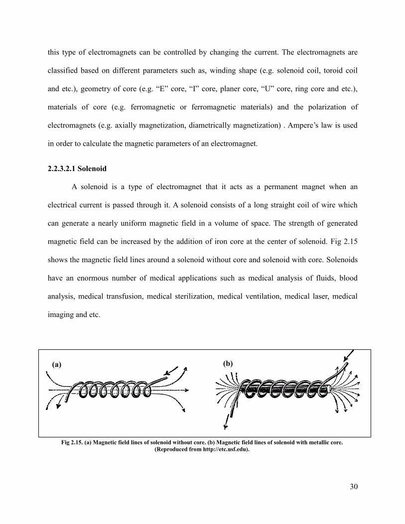
magnetic field can be increased by the addition of iron core at the center of solenoid. Fig 2.15
shows the magnetic field lines around a solenoid without core and solenoid with core. Solenoids
have an enormous number of medical applications such as medical analysis of fluids, blood
analysis, medical transfusion, medical sterilization, medical ventilation, medical laser, medical
imaging and etc.
(a) (b)
Fig 2.15. (a) Magnetic field lines of solenoid without core. (b) Magnetic field lines of solenoid with metallic core.
(Reproduced from http://etc.usf.edu).
31
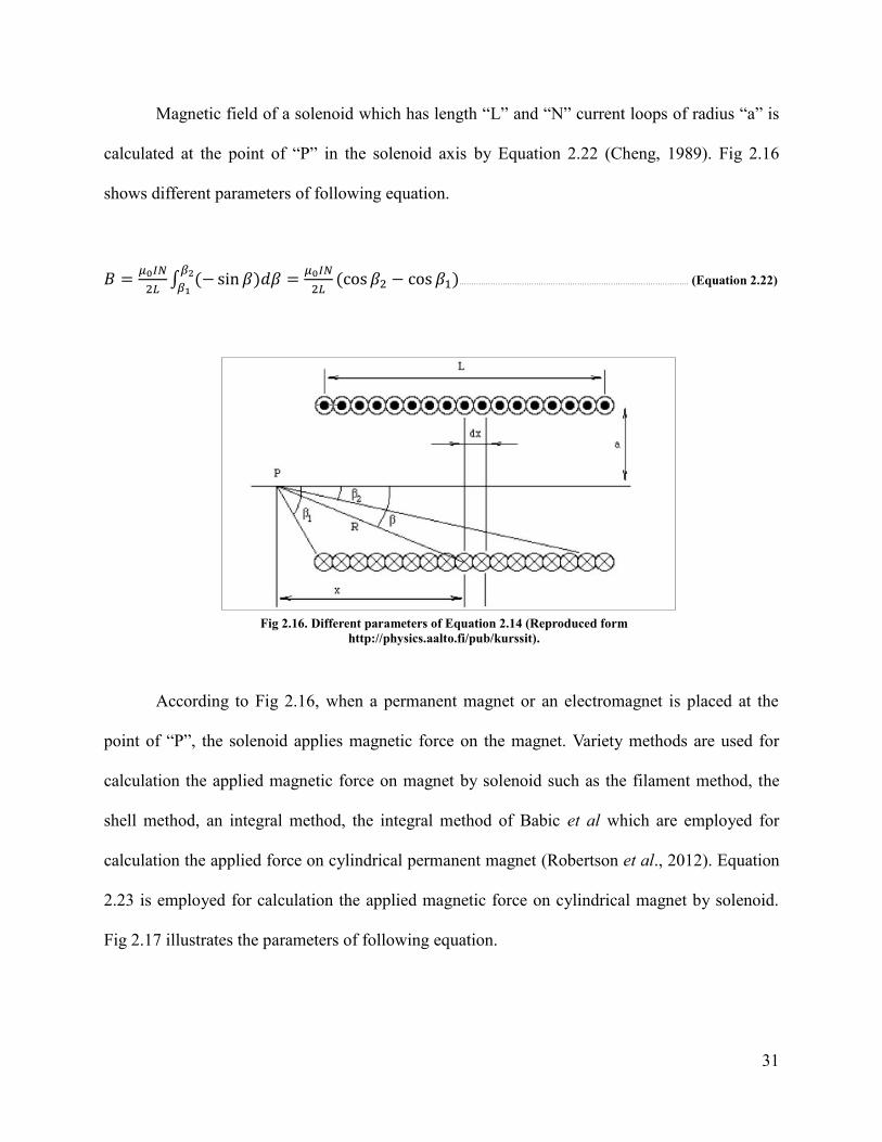
Magnetic field of a solenoid which has length “L” and “N” current loops of radius “a” is
calculated at the point of “P” in the solenoid axis by Equation 2.22 (Cheng, 1989). Fig 2.16
shows different parameters of following equation.
𝐵 𝜇0𝐼𝑁
𝐿∫ − sin 𝛽 𝑑𝛽
𝜇0𝐼𝑁
𝐿 cos 𝛽 − cos 𝛽
𝛽
𝛽1………………………………………………………………..…………………. (Equation 2.22)
According to Fig 2.16, when a permanent magnet or an electromagnet is placed at the
point of “P”, the solenoid applies magnetic force on the magnet. Variety methods are used for
calculation the applied magnetic force on magnet by solenoid such as the filament method, the
shell method, an integral method, the integral method of Babic et al which are employed for
calculation the applied force on cylindrical permanent magnet (Robertson et al., 2012). Equation
2.23 is employed for calculation the applied magnetic force on cylindrical magnet by solenoid.
Fig 2.17 illustrates the parameters of following equation.
Fig 2.16. Different parameters of Equation 2.14 (Reproduced form
http://physics.aalto.fi/pub/kurssit).
32
𝐹𝑧3 𝐵𝑟𝑁𝐼
𝑙𝑐[ 𝑐 𝑟𝑐]∫ ∫ ∑ [𝑒 𝑚6 𝑧3]𝑑 𝑑𝑧
{ , }𝑒1
𝑐
𝑟𝑐
𝑙𝑐
𝑙𝑐 ……………………………………………………………………..…………………. (Equation 2.23)
Definitions:
Br: Magnet remanence
N: Coil turn
I: Coil current
lc: Coil length
Rc: Coil outer radius
rc: Coil inner radius
𝑧3 [1 −
𝑚 ]𝐾 𝑚 − 𝐸 𝑚 ………………………………………….……………………………………………………………………..…………………. (Equation 2.24)
𝑚 4 𝑟
𝑚 ………………………………………………………………………………….…………………………………………………………………………………..…………………. (Equation 2.25)
𝑚6 [ 𝑚 + ]
+ [𝑧 +
𝑒 𝑚 − 𝑧 ]
……………………………………..………………………………………………………………..…………………. (Equation 2.26)
(a) (b)
Fig 2.17. (a) Three dimensional sketch of solenoid and cylindrical magnet. (b) This geometry describe the terms of
Equation 2.16 (Reproduced from Robertson et al. (2012)).

33
2.2.4 Magnetic Particles
Magnetic particles are valuable materials which can be easily manufactured in a wide
range of size from nanometer to micrometer (Aytur, 2007). Magnetic particles are used for a
wide range of medical applications such as immunoassay, separation, magnetic resonance
magnetic resonance imaging (MRI), drug delivery systems and etc. Different types of
biomolecules such as antigens, antibodies, and DNA strands can be easily attached to these
particles due to their specific surface functionalization (Fig 2.18). Spherical shape and large
surface area are other important properties of these particles which are desired in mass
transferring (Pamme, 2006).
2.2.4.1 Force on Magnetic Particles
Magnetic force is applied on magnetic particles when they are placed inside a magnetic
field. This force depends on strength and gradient of the applied magnetic field, the volume of
the particles and the difference in magnetic susceptibilities of particles and their medium.
Equation 2.27 is utilized for calculation the applied force on magnetic particles (Gijs, 2004).
Fig 2.18. Biomolecules such as antibodies, antigens, DNA strand can be attached to the
surface of magnetic particles for biomedical applications (Reproduced from Pamme,
(2006)).

34
𝐹 𝑉 𝑥
𝜇0 𝐵 ∇ 𝐵 …………………………………………………………………………………………………...………………………………………………………………..……..(Equation 2.27)
Definition:
V: Volume of particles
∆x: The difference in magnetic susceptibilities
(B.∇)B: Strength and gradient of magnetic particles
2.3 Combination of Microfluidics and Magnetism
In recent years the microfluidics and the magnetism have been combined. Combination
of microfluidics and magnetism is very useful especially for medical applications. Two
approaches are used for controlling the magnetic particles inside the microfluidic systems.
Firstly, permanent magnets or electromagnets which they are used outside of the microfluidic
systems. Secondly, micro fabricated permanent magnets or electromagnets which they are used
inside the microfluidic systems (Pamme, 2006). Magnetic particles are controlled for many
purposes such as trapping of particles within a microfluidic chamber, transporting of magnetic
particles between reagents, washing and detection of magnetic particles and so on.
2.3.1 Trapping of Magnetic Particles
Trapping of magnetic particles is useful for cell sorting and cell identification
applications. For cell sorting or cell identification applications, cells are labeled by magnetic
particles. In order to trap magnetic particles in a specific chamber of microfluidic platform, saw-
tooth shaped permanent magnets or electromagnetic arrays which they are turned on alternatively
are used. By employing these types of magnets, magnetic particles are trapped at locations with
maximum magnetic field. As a final step, target cells are sorted and identified from background
population (Wirix et al., 2005; Lee et al., 2001; Burger et al., 2012).
35
2.3.2 Transporting of Magnetic Particles
Magnetic particles are transported between different chambers of a microfluidic platform
for different applications such as DNA separation, mRNA purification and so on. In this method
biomolecules are labeled with magnetic particles and they moved between different reagents by
employing variety shapes of permanent magnets or electromagnetic arrays. Shapes of permanent
magnets and numbers of electromagnetic arrays are chosen based on the shape of microfluidic
platforms. Strohmeier et al (2013) presented a magnetic platform for manipulation of magnetic
particles within a centrifugal microfluidic platform. This platform was designed and fabricated
by permanent magnet for transporting magnetic particles between three chambers for binding,
washing and elution of DNA. In this method, spinning speed of centrifugal microfluidic platform
should be zero during the manipulation of magnetic particles.
2.3.3 Detection of Magnetic Particles
Bimolecular detection assays are very challenging issues for diagnosis purposes.
Magnetic platform can be used for reduce the time-consuming problem of biological bead-based
assays in detection of biomolecules. Bruls et al (2009) described using magnetic nanoparticles in
stationary microfluidic system for immunoassays and detection of these particles by employing
optomagnetic technology. This method is based on actuating magnetic particles by using two
electromagnetic at the top and bottom of the microfluidic system.

36
Chapter 3. METHODOLOGY
The procedure to design and development of an electromagnetic platform for
manipulation magnetic particles is discussed in the following sections. This platform can be used
for several usages such as, washing and detecting steps in sandwich immunoassays and
purification of biomolecules from background populations (e.g. DNA purification). This part of
study is divided into six divisions; designing the microfluidic disc platform by AutoCAD
software, finding the best design of electromagnetic platform to produce desired magnetic field
pattern by COMSOL software, calculating the forces which act on magnetic particles by
MATLAB software, changing the variables of the platform and measuring the values of produced
magnetic flux density over limited space of microfluidic chamber (COMSOL), obtaining the
general magnetic flux density equation for this platform by MATLAB, and finally acquiring
appropriate parameters of electromagnetic platform to generate desired force. The following
block diagram (Fig 3.1) shows the procedures of this study. Although the mentioned procedures
have been done for DNA applications, this platform can be designed easily for other applications
by obtaining the general magnetic force equation.
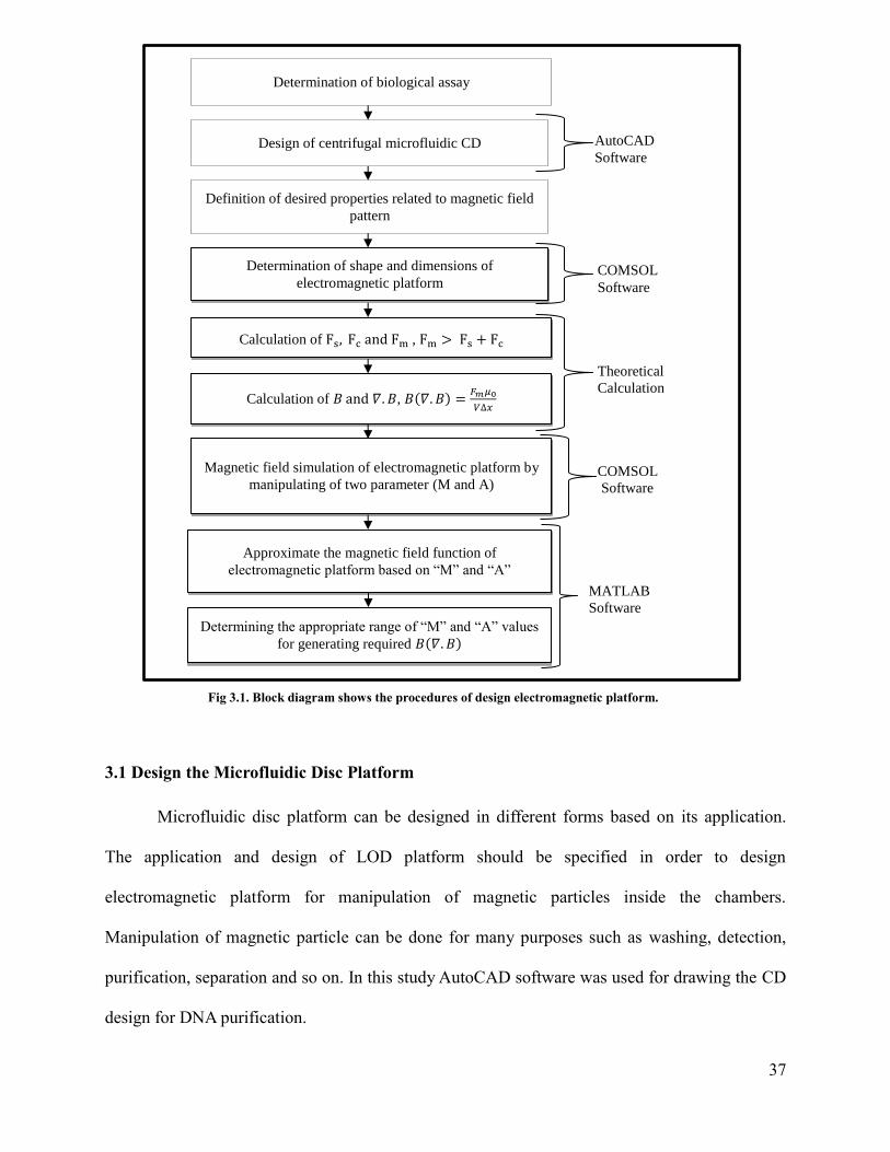
37
3.1 Design the Microfluidic Disc Platform
Microfluidic disc platform can be designed in different forms based on its application.
The application and design of LOD platform should be specified in order to design
electromagnetic platform for manipulation of magnetic particles inside the chambers.
Manipulation of magnetic particle can be done for many purposes such as washing, detection,
purification, separation and so on. In this study AutoCAD software was used for drawing the CD
design for DNA purification.
Fig 3.1. Block diagram shows the procedures of design electromagnetic platform.
AutoCAD
Software
COMSOL
Software
Theoretical
Calculation
COMSOL
Software
MATLAB
Software
Calculation of Fs, Fc and Fm , Fm > Fs + Fc
Calculation of 𝐵 and 𝛻 𝐵, 𝐵 𝛻 𝐵 𝐹𝑚𝜇0
𝑉 𝑥
Design of centrifugal microfluidic CD
Determination of shape and dimensions of
electromagnetic platform
Determination of biological assay
Definition of desired properties related to magnetic field
pattern
Magnetic field simulation of electromagnetic platform by
manipulating of two parameter (M and A)
Approximate the magnetic field function of
electromagnetic platform based on “M” and “A”
Determining the appropriate range of “M” and “A” values
for generating required 𝐵 𝛻 𝐵

38
Magnetic particles act as mobile solid support in some biological assays (e.g. DNA
extraction and mRNA purification). These magnetic particles play fundamental role in such
assays by displacing between different reagents. DNA purification is an example of these kinds
of assays. Hence, complex set-up and design for CD is required in order to transportation of fluid
and manipulation magnetic particles between different chambers. The complexity of the CD
design can be reduced by applying suitable external magnetic field on CD. This magnetic field
helps to move particles from one chamber to another one easily. Therefore, DNA purification
was implemented on CD with three chambers. Design of CD for this application consists of
binding chamber, washing chamber, and elution chamber (Strohmeier et al., 2013). Fig 3.2
displays the design of CD for DNA purification. In this study following design was used for
displaying the movement of magnetic particles inside the chambers.
Fig 3.2. Design of CD for DNA purification (Reproduced from Strohmeier et al. (2013)).
39
3.2 Developing the Magnetic Field Pattern
This study aims to design an electromagnetic platform which produce desired magnetic
field pattern over centrifugal microfluidic CD. As mentioned in Chapter 2, rotational motion of
microfluidic CD provides many advantages to perform biological assays. Therefore,
manipulating of magnetic particles during the rotation of CD plays a key role in time-reducing of
process and integration of assay. On the other hand, CD platforms are designed in standard size
(limited size) with different shapes of chambers and channels to perform sequential steps of
bioassay. So, the chambers are very close together and magnetic particles should be controlled
very accurately. Magnetic particles can be controlled within the chambers accurately during the
rotation of CD by applying desired magnetic field pattern. There are three main objectives in
order to get desired pattern. Firstly, the magnetic field pattern should be symmetry relative to z-
axis in cylindrical coordinate. Secondly, the maximum values of magnetic field pattern should be
located at the target places (chambers that contain magnetic particles) over the CD. Finally, the
magnetic field pattern should be constant for the points which have constant distance from centre
of coordinate.
Ring permanent magnet is proper option as a magnetic platform to provide these three
objectives. The ring shape of magnet produces symmetric magnetic field pattern relative to z-
axis. Additionally, axially magnetized rings produce maximum magnetic field over the surface of
magnet and this magnetic field pattern is constant for any points with specific distance from
centre of coordinate as well (Fig 3.3). Although permanent ring magnet provides many benefits,
the magnetic field is not controllable.

40
In this study electromagnetic platform has been employed to overcome this problem.
Consequently, this study has attempts to design electromagnetic platform which is switched
between “on” and “off” positions. In “on” positions it produces magnetic field pattern same as
ring permanent magnet while in “off” positions it does not produce magnetic field. COMSOL
software was used for simulation the magnetic field pattern around the electromagnetic platform.
3.2.1 Electromagnetic Platform (Symmetric Magnetic Field Pattern)
There are several reasons why symmetric magnetic field pattern is necessary. First of all,
CD obviously has the round shape (i.e. it is axially symmetric). In the second place, microfluidic
CD is divided into several partitions for performing several assays simultaneously. So,
symmetric magnetic field should be applied on the CD to affects all partitions identically. In
addition, the magnetic field should be applied on the small area of each partition. For these
reasons, ring-shaped electromagnetic platform has been used for generating symmetric magnetic
field pattern. Dimensions of an electromagnetic ring platform are based on CD design and its
application. On the other hand, the efficacy of magnetic platform on magnetic particles depends
on the distance between them. Table 3.1 demonstrates the dimensions of ring electromagnetic
platform which are designed for microfluidic CD for DNA purification.
Fig 3.3. Magnetic field lines around ring permanent magnet.

41
Table 3.1.Dimensions of electromagnetic platform.
3.2.2 Electromagnetic Platform (Maximum Values of Magnetic Field Pattern)
Imagine electromagnetic platform which is located at the centre of Cartesian coordinates.
The maximum values of magnetic field have been distributed in magnetic field pattern along “x”
direction. The location of maximum values on this pattern plays fundamental role in controlling
magnetic particles. Therefore, magnetic platform should be designed with specific features to
produce desired magnetic field pattern (i.e. the pattern which have maximum values at target
places). The locations of maximum values can be determined based on the CD design and its
application. Moreover, the maximum values of magnetic field should be applied on the small
areas of CD (specific chambers) due to the chambers proximity to each other.
The CD for declared application (i.e. transporting of magnetic particles for DNA
purification) require the maximum values of magnetic field above the electromagnetic ring. In
other word, the magnetic field pattern along “x” direction should have two maximum values at
the overhead of ring. Fig 3.4 displays the desired location of maximum magnetic field along “x”
direction.
Application DNA Purification
Inner Radius (Rin) 30(mm)
Outer Radius (Rout) 45(mm)
Height (h) 19(mm)
Distance to magnetic particles (d) 10(mm)

42
Once the desired locations for peak of pattern were determined, different designs of
solenoid electromagnet (simple solenoid and combination of solenoids) were simulated to meet
the desired pattern. Solenoid was chosen for simulation due to its ability to produce axial
magnetic field. According to the magnetic field equation of solenoid, simple solenoid with air
core produces maximum value of magnetic field at the centre. Fig 3.5.a displays the simple
solenoid with air core. Thus, the following factors have been applied on the simple solenoid to
disperse the maximum value from centre toward the edges.
- Using the combination of solenoid in circular configuration.
- Using material with permeability higher than air as a core of solenoid.
The proposed electromagnetic platform is shown in Fig 3.5.b.
Fig 3.4. Desired locations of maximum magnetic field along “x” direction.

43
3.2.3 Electromagnetic Platform (Nearly Homogenous Magnetic Field Pattern)
In this section another type of magnetic field pattern is considered. This pattern is related
to the magnetic field value of points which are located with specific distance directly above the
electromagnetic platform in a circular shape. The homogeneity characteristic of this magnetic
field pattern is another objective of the platform design. As discussed earlier about this
parameter, the rotational motion of CD provides many advantages for performing bioassays.
Additionally, CD is used for performing several assays simultaneously. Hence, magnetic field
should be same for all points which have specific radial distance from the centre of platform (Fig
3.6). In this condition, during the rotation of CD, all target chambers experience same magnetic
field.
Fig 3.5. (a) Simple solenoid with air core (red color indicates maximum
magnetic field strength around solenoid). (b) Electromagnetic platform
which constructed from combination of solenoids (4 solenoids).
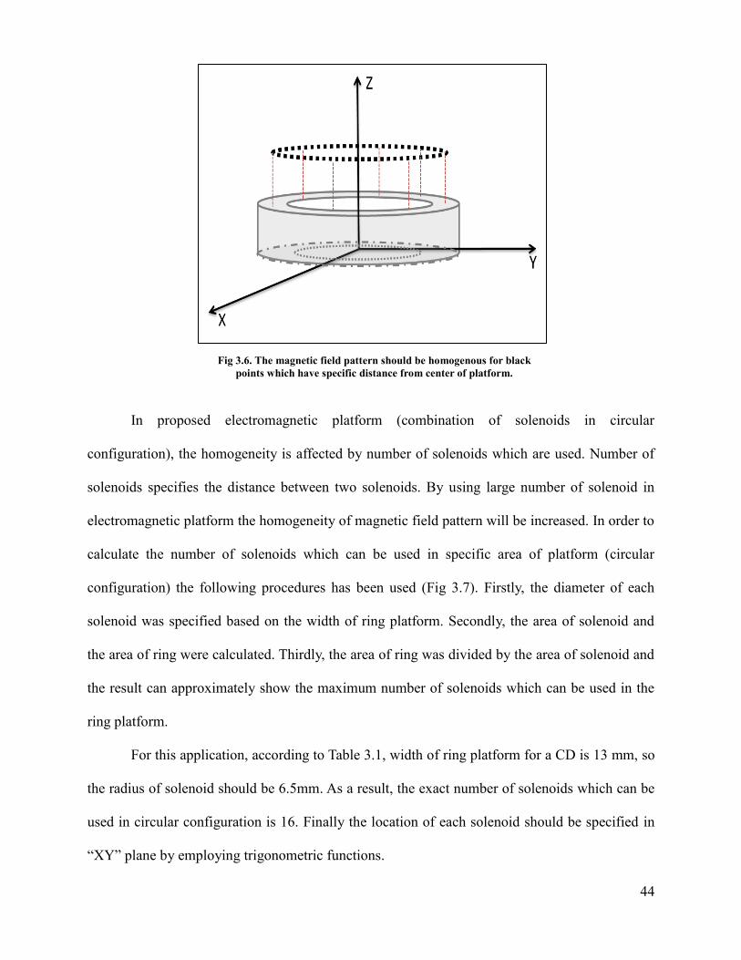
44
In proposed electromagnetic platform (combination of solenoids in circular
configuration), the homogeneity is affected by number of solenoids which are used. Number of
solenoids specifies the distance between two solenoids. By using large number of solenoid in
electromagnetic platform the homogeneity of magnetic field pattern will be increased. In order to
calculate the number of solenoids which can be used in specific area of platform (circular
configuration) the following procedures has been used (Fig 3.7). Firstly, the diameter of each
solenoid was specified based on the width of ring platform. Secondly, the area of solenoid and
the area of ring were calculated. Thirdly, the area of ring was divided by the area of solenoid and
the result can approximately show the maximum number of solenoids which can be used in the
ring platform.
For this application, according to Table 3.1, width of ring platform for a CD is 13 mm, so
the radius of solenoid should be 6.5mm. As a result, the exact number of solenoids which can be
used in circular configuration is 16. Finally the location of each solenoid should be specified in
“XY” plane by employing trigonometric functions.
Fig 3.6. The magnetic field pattern should be homogenous for black
points which have specific distance from center of platform.
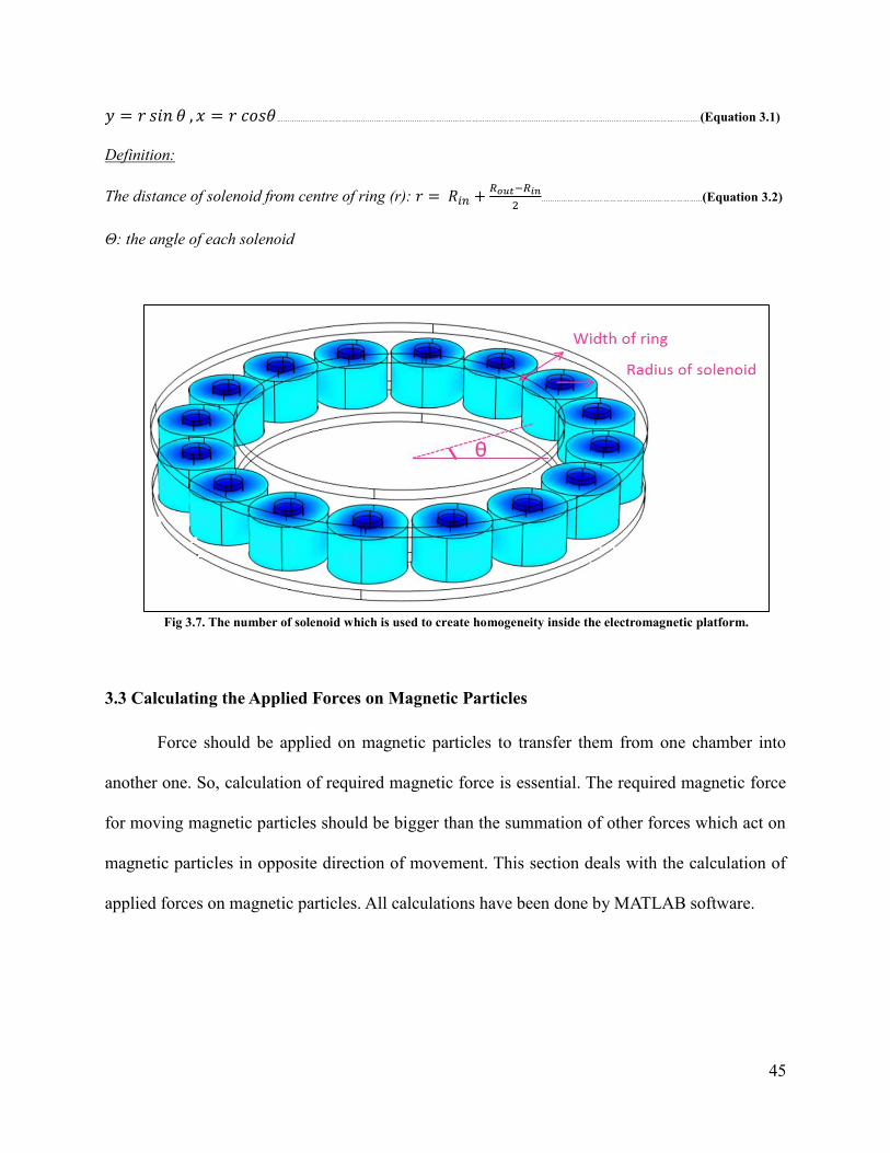
45
𝑦 𝑠𝑖𝑛 𝜃 , 𝑥 𝑐𝑜𝑠𝜃…………………………………………..………………………..………………………..……………………………………………..……………………..………..(Equation 3.1)
Definition:
The distance of solenoid from centre of ring (r): + 𝑜𝑢𝑡 𝑖𝑛
………………………..……………………….………………(Equation 3.2)
Θ: the angle of each solenoid
3.3 Calculating the Applied Forces on Magnetic Particles
Force should be applied on magnetic particles to transfer them from one chamber into
another one. So, calculation of required magnetic force is essential. The required magnetic force
for moving magnetic particles should be bigger than the summation of other forces which act on
magnetic particles in opposite direction of movement. This section deals with the calculation of
applied forces on magnetic particles. All calculations have been done by MATLAB software.
Fig 3.7. The number of solenoid which is used to create homogeneity inside the electromagnetic platform.

46
3.3.1Centrifugal Force
This force is due to the rotational speed of microfluidic CD. In fact, when CD is rotating
with specific rotational speed, all points of CD will experience the centrifugal force. As
explained in microfluidic section, this force is proportional with the density of magnetic
particles, the radial distance of magnetic particles from the centre of CD and rotational speed of
CD. Table 3.2 shows the required information about the magnetic particles and conditions of
rotating CD for different steps of DNA purification (Strohmeier et al., 2013).
Table 3.2.The information about the magnetic particles and condition of rotating CD
(Reproduced from Strohmeier et al.(2013)).
The centrifugal force density is calculated by Equation 3.3. In order to calculate the
centrifugal force, the density of magnetic particles should be multiplied to centrifugal force
density equation.
𝐹𝐶𝑒 𝑟 𝑓𝑢𝑔𝑒 𝑉𝑚𝑎𝑔 𝑒 𝑝𝑎𝑟 𝑙𝑒 × × × 1 6 𝑒 3 𝑁 1 6 𝑚𝑁 …………….. (Equation 3.3)
Parameters Value
Rotational Speed (w) 20.94(rad/sec)
Diameter of magnetic sphere (D) 1.05e-6
(m)
Density of magnetic sphere (dsphere) 1.8 (g/cm3)
Volume of magnetic particles (Vmagnetic partticles) 4e-5 (L)
Mass of Volume particles(m) 7.2e-6
(Kg)
Density of volume particles (ρ) 1.8 (Kg/L)
Radial distance form centre of CD(r) 0.04(m)
47
3.3.2 Surface Tension Force
Another type of force which should be considered is surface tension force. Actually
magnetic particles are in liquid phase when they are in binding chamber and they should cross
from the gas phase to get to another chamber (washing chamber). Surface tension force is a
result of transporting magnetic particles from liquid phase to gas phase. Table 3.3 shows required
parameters for calculation this force (Strohmeier et al., 2013).
Table 3.3. The required information for calculating surface tension force.
(Reproduced form Strohmeier et al. (2013)).
The following calculation was done based on the information of Table 3.3 and the
Equation 3.4 is used to calculate surface tension force.
𝐹 𝑢𝑟𝑓𝑎 𝑒 𝑒 𝑜 6 3 × 𝜋 3 × 𝜎𝑙 𝑞𝑢 × 𝑉𝑚𝑎𝑔 𝑒 𝑝𝑎𝑟 𝑙𝑒 3 0 448𝑒 3 𝑁 0 448 𝑚𝑁
…………………………………………..………………………..………………………..………………………..………………………..………………………..………………………..………………………..………………………(Equation 3.4)
Parameters Value
Susceptibility of magnetic particles(Xmag) 0.29
Susceptibility of liquid (water) (Xliquid) 9e-63132
Permeability of vacuum (μ0) 1.25e-6
(NA2)
Surface tension of liquid(water) (σliquid) 72.5(mNm-1
)
Volume of magnetic particles (Vmagnetic particles) 4(mm3)
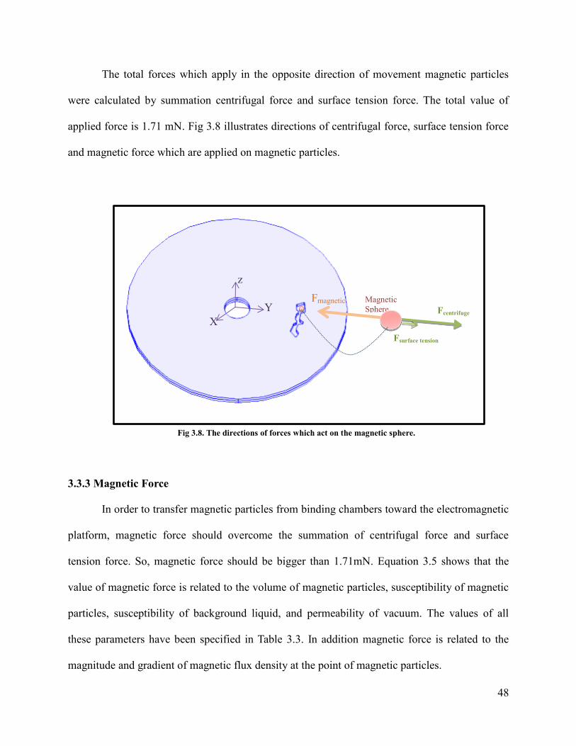
48
The total forces which apply in the opposite direction of movement magnetic particles
were calculated by summation centrifugal force and surface tension force. The total value of
applied force is 1.71 mN. Fig 3.8 illustrates directions of centrifugal force, surface tension force
and magnetic force which are applied on magnetic particles.
3.3.3 Magnetic Force
In order to transfer magnetic particles from binding chambers toward the electromagnetic
platform, magnetic force should overcome the summation of centrifugal force and surface
tension force. So, magnetic force should be bigger than 1.71mN. Equation 3.5 shows that the
value of magnetic force is related to the volume of magnetic particles, susceptibility of magnetic
particles, susceptibility of background liquid, and permeability of vacuum. The values of all
these parameters have been specified in Table 3.3. In addition magnetic force is related to the
magnitude and gradient of magnetic flux density at the point of magnetic particles.
Fig 3.8. The directions of forces which act on the magnetic sphere.
Magnetic
Sphere Fcentrifuge
Fsurface tension
Fmagnetic
z
Y
X
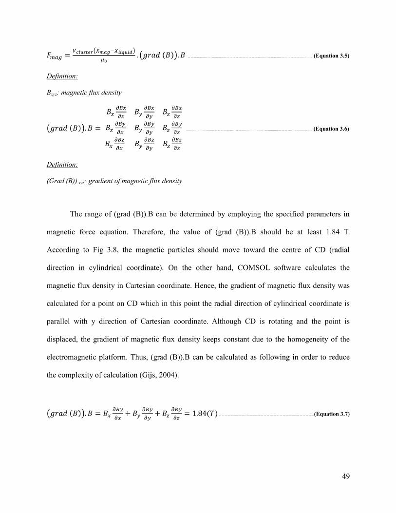
49
𝐹𝑚𝑎𝑔 𝑉𝑐𝑙𝑢𝑠𝑡𝑒𝑟(𝑋 𝑎𝑔 𝑋𝑙𝑖𝑞𝑢𝑖𝑑)
𝜇0 (𝑔 𝑎𝑑 𝐵 ) 𝐵 ………………………..………………………..………………………..…………………………………….. (Equation 3.5)
Definition:
Bxyz: magnetic flux density
(𝑔 𝑎𝑑 𝐵 ) 𝐵
𝐵𝑥𝜕𝐵𝑥
𝜕𝑥𝐵𝑦
𝜕𝐵𝑥
𝜕𝑦𝐵𝑧
𝜕𝐵𝑥
𝜕𝑧
𝐵𝑥𝜕𝐵𝑦
𝜕𝑥𝐵𝑦
𝜕𝐵𝑦
𝜕𝑦𝐵𝑧
𝜕𝐵𝑦
𝜕𝑧
𝐵𝑥𝜕𝐵𝑧
𝜕𝑥𝐵𝑦
𝜕𝐵𝑧
𝜕𝑦𝐵𝑧
𝜕𝐵𝑧
𝜕𝑧
………………………………………….. ……………………….. ……………………….. …………………(Equation 3.6)
Definition:
(Grad (B)) xyz: gradient of magnetic flux density
The range of (grad (B)).B can be determined by employing the specified parameters in
magnetic force equation. Therefore, the value of (grad (B)).B should be at least 1.84 T.
According to Fig 3.8, the magnetic particles should move toward the centre of CD (radial
direction in cylindrical coordinate). On the other hand, COMSOL software calculates the
magnetic flux density in Cartesian coordinate. Hence, the gradient of magnetic flux density was
calculated for a point on CD which in this point the radial direction of cylindrical coordinate is
parallel with y direction of Cartesian coordinate. Although CD is rotating and the point is
displaced, the gradient of magnetic flux density keeps constant due to the homogeneity of the
electromagnetic platform. Thus, (grad (B)).B can be calculated as following in order to reduce
the complexity of calculation (Gijs, 2004).
(𝑔 𝑎𝑑 𝐵 ) 𝐵 𝐵𝑥𝜕𝐵𝑦
𝜕𝑥+ 𝐵𝑦
𝜕𝐵𝑦
𝜕𝑦+ 𝐵𝑧
𝜕𝐵𝑦
𝜕𝑧 1 84 𝑇 ………………………..………………………..……………………………………(Equation 3.7)
50
3.4 Measuring the Magnetic Flux Density
Different designs of electromagnetic platform produce the different magnetic flux density
at the location of magnetic particles. The design of an electromagnetic platform depends on
several parameters such as dimension of platform, the material of platform, the number of
solenoids which are used in the platform structure, the current of solenoids, the number of turns
in solenoid, distance of particle from platform and so on. Some of these parameters must be kept
constant and some of them can be varied in specific range. Hence, the main objective of this part
is investigation the effect of each parameter on produced magnetic flux density and obtaining the
design which can produce 1.84T or more magnetic flux density at the target point.
3.4.1 Dimensions of Electromagnetic Platform
The size of electromagnetic platform has effect on the produced magnetic flux density. In
fact, bigger electromagnetic platform provides more spaces to increase the number of turns in
each solenoid. As a result magnetic flux density will be amplified around platform. The size of
inner radius and outer radius of platform should be kept constant based on the design of
microfluidic CD. Height of platform is only variable parameter in platform. Nevertheless,
miniaturization is one of the main purposes of “point of care" devices and it limits the size of
electromagnetic platform. Therefore, in this study the dimension of platform was considered as a
constant parameter (inner radius=24.5mm, outer radius=37.5mm and height=15mm). Fig 3.9
displays the dimension of electromagnetic platform.
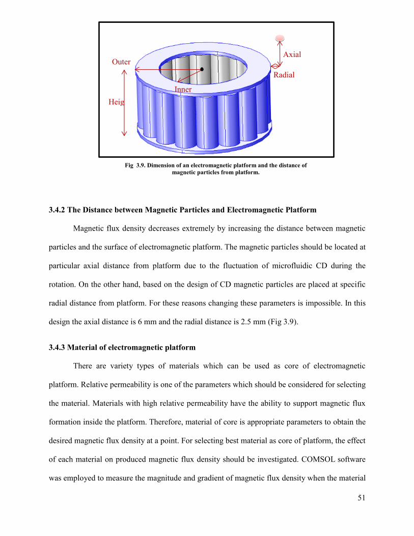
51
Heig
ht
Outer
radius
Inner
radius
Axial
distance
Radial
distance
3.4.2 The Distance between Magnetic Particles and Electromagnetic Platform
Magnetic flux density decreases extremely by increasing the distance between magnetic
particles and the surface of electromagnetic platform. The magnetic particles should be located at
particular axial distance from platform due to the fluctuation of microfluidic CD during the
rotation. On the other hand, based on the design of CD magnetic particles are placed at specific
radial distance from platform. For these reasons changing these parameters is impossible. In this
design the axial distance is 6 mm and the radial distance is 2.5 mm (Fig 3.9).
3.4.3 Material of electromagnetic platform
There are variety types of materials which can be used as core of electromagnetic
platform. Relative permeability is one of the parameters which should be considered for selecting
the material. Materials with high relative permeability have the ability to support magnetic flux
formation inside the platform. Therefore, material of core is appropriate parameters to obtain the
desired magnetic flux density at a point. For selecting best material as core of platform, the effect
of each material on produced magnetic flux density should be investigated. COMSOL software
was employed to measure the magnitude and gradient of magnetic flux density when the material
Fig 3.9. Dimension of an electromagnetic platform and the distance of
magnetic particles from platform.

52
of core is changed. Table 3.4 shows several materials with different relative permeability and
electrical conductivity which were used in this study. The relative permeability of these material
is higher than 1.0 (relative permeability of air).
3.4.4 Ampere Turns of Coils
As mentioned earlier, the proposed electromagnetic platform consists of 16 solenoids in
its structure. In order to preserve the homogeneity of electromagnetic platform, all solenoids
should generate equal magnetic flux density at the point of interest. So, the features of all
solenoids should be similar. These features consist of the resistance of wire and current which
pass through the wire. The resistance of wire depends on three parameters; resistivity, length and
cross sectional area of wire. So, the material, length and diameter of wires in all solenoids must
be selected equally. Another parameter is current. For passing same current through all solenoids,
both parallel and series connection can be used to connect solenoids to the source of voltage. In
this study, all solenoids were connected to each other in parallel.
By increasing the current, magnetic flux density of platform will be increased
dramatically. However, this platform has been designed for “point of care” testing and portable
devices and there is limitation for the usable range of current. So, understanding the value of the
Material Relative
permeability μ/μ0
Electrical conductivity
σ(S/m) at 20° C
Nickel 650 1.43e7
Mild steel 2000 6.99e6
Iron(99.8% pure) 4000 1.00e7
Silicon iron 8000 6.96e6
Mu-metal 100000 1.74e6
Purified iron (99.95%) 200000 1.029e7
Table 3.4. Relative permeability and electrical conductivity of materials.
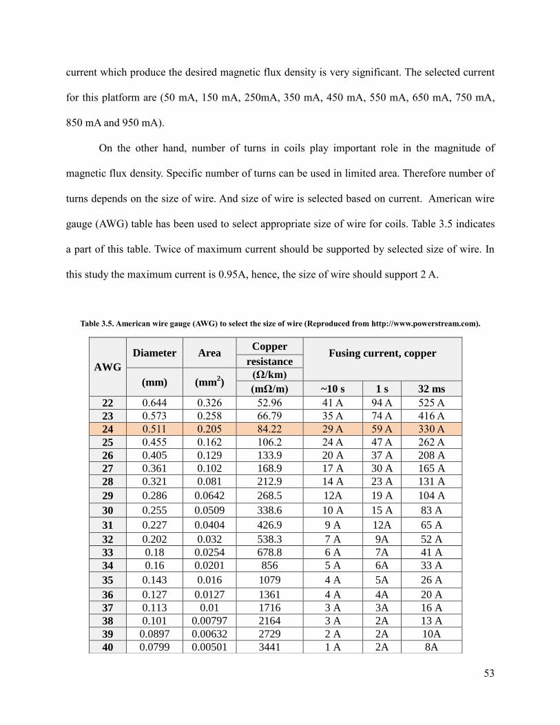
53
current which produce the desired magnetic flux density is very significant. The selected current
for this platform are (50 mA, 150 mA, 250mA, 350 mA, 450 mA, 550 mA, 650 mA, 750 mA,
850 mA and 950 mA).
On the other hand, number of turns in coils play important role in the magnitude of
magnetic flux density. Specific number of turns can be used in limited area. Therefore number of
turns depends on the size of wire. And size of wire is selected based on current. American wire
gauge (AWG) table has been used to select appropriate size of wire for coils. Table 3.5 indicates
a part of this table. Twice of maximum current should be supported by selected size of wire. In
this study the maximum current is 0.95A, hence, the size of wire should support 2 A.
Table 3.5. American wire gauge (AWG) to select the size of wire (Reproduced from http://www.powerstream.com).
AWG
Diameter Area Copper
Fusing current, copper
resistance
(mm) (mm2)
(Ω/km)
(mΩ/m) ~10 s 1 s 32 ms
22 0.644 0.326 52.96 41 A 94 A 525 A
23 0.573 0.258 66.79 35 A 74 A 416 A
24 0.511 0.205 84.22 29 A 59 A 330 A
25 0.455 0.162 106.2 24 A 47 A 262 A
26 0.405 0.129 133.9 20 A 37 A 208 A
27 0.361 0.102 168.9 17 A 30 A 165 A
28 0.321 0.081 212.9 14 A 23 A 131 A
29 0.286 0.0642 268.5 12A 19 A 104 A
30 0.255 0.0509 338.6 10 A 15 A 83 A
31 0.227 0.0404 426.9 9 A 12A 65 A
32 0.202 0.032 538.3 7 A 9A 52 A
33 0.18 0.0254 678.8 6 A 7A 41 A
34 0.16 0.0201 856 5 A 6A 33 A
35 0.143 0.016 1079 4 A 5A 26 A
36 0.127 0.0127 1361 4 A 4A 20 A
37 0.113 0.01 1716 3 A 3A 16 A
38 0.101 0.00797 2164 3 A 2A 13 A
39 0.0897 0.00632 2729 2 A 2A 10A
40 0.0799 0.00501 3441 1 A 2A 8A
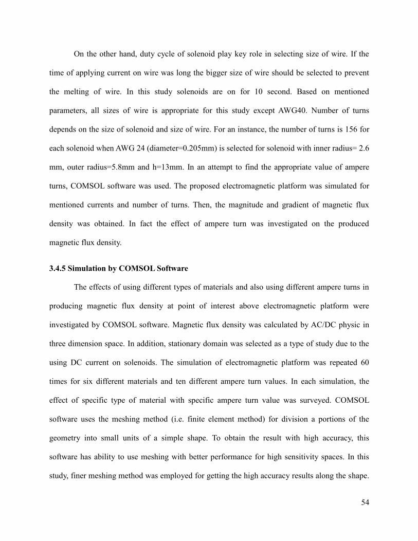
54
On the other hand, duty cycle of solenoid play key role in selecting size of wire. If the
time of applying current on wire was long the bigger size of wire should be selected to prevent
the melting of wire. In this study solenoids are on for 10 second. Based on mentioned
parameters, all sizes of wire is appropriate for this study except AWG40. Number of turns
depends on the size of solenoid and size of wire. For an instance, the number of turns is 156 for
each solenoid when AWG 24 (diameter=0.205mm) is selected for solenoid with inner radius= 2.6
mm, outer radius=5.8mm and h=13mm. In an attempt to find the appropriate value of ampere
turns, COMSOL software was used. The proposed electromagnetic platform was simulated for
mentioned currents and number of turns. Then, the magnitude and gradient of magnetic flux
density was obtained. In fact the effect of ampere turn was investigated on the produced
magnetic flux density.
3.4.5 Simulation by COMSOL Software
The effects of using different types of materials and also using different ampere turns in
producing magnetic flux density at point of interest above electromagnetic platform were
investigated by COMSOL software. Magnetic flux density was calculated by AC/DC physic in
three dimension space. In addition, stationary domain was selected as a type of study due to the
using DC current on solenoids. The simulation of electromagnetic platform was repeated 60
times for six different materials and ten different ampere turn values. In each simulation, the
effect of specific type of material with specific ampere turn value was surveyed. COMSOL
software uses the meshing method (i.e. finite element method) for division a portions of the
geometry into small units of a simple shape. To obtain the result with high accuracy, this
software has ability to use meshing with better performance for high sensitivity spaces. In this
study, finer meshing method was employed for getting the high accuracy results along the shape.
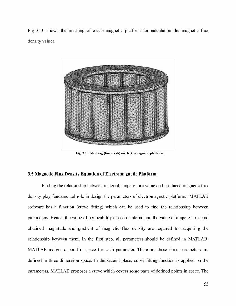
55
Fig 3.10 shows the meshing of electromagnetic platform for calculation the magnetic flux
density values.
3.5 Magnetic Flux Density Equation of Electromagnetic Platform
Finding the relationship between material, ampere turn value and produced magnetic flux
density play fundamental role in design the parameters of electromagnetic platform. MATLAB
software has a function (curve fitting) which can be used to find the relationship between
parameters. Hence, the value of permeability of each material and the value of ampere turns and
obtained magnitude and gradient of magnetic flux density are required for acquiring the
relationship between them. In the first step, all parameters should be defined in MATLAB.
MATLAB assigns a point in space for each parameter. Therefore these three parameters are
defined in three dimension space. In the second place, curve fitting function is applied on the
parameters. MATLAB proposes a curve which covers some parts of defined points in space. The
Fig 3.10. Meshing (fine mesh) on electromagnetic platform.

56
accuracy of covering points by curve can be changed, when the method of fitting is changed. The
SSE value shows the error of method. So, the value of SSE helps to find the best method of
fitting. In this study linear model poly 34 was selected. In this equation the order of ampere turn
is 3 and the order of material is 4. This model can cover all values of three parameters in 3D
space. In addition the SSE value of this model is minimum compared to other model. Finally,
MATLAB shows the relationship between the parameters as an equation. By employing above
procedures, the obtained equation shows the relationship between magnetic flux density ((grad
(B)).B), permeability of material and ampere turn. Based on the selected method for fitting, the
order of equation and the value of coefficients are changed.
3.6 Acquiring Appropriate Parameters for Design
The final step is acquiring the exact value of parameters for design the electromagnetic
platform. The magnetic force should be at least 1.71mN and for producing this force 1.84 T
magnetic flux density is required at the point of magnetic particles. Therefore, desired value of
magnetic flux density will be gained by employing the obtained equation and changing the
variable parameters in allowed ranges. In this study MATLAB software has been used to define
the allowed ranges of materials and ampere turns and also for calculation the magnetic flux
density by magnetic flux density equation.
57
Chapter 4. RESULTS AND DISCUSSION
The results generated by proposed electromagnetic platform are described in the
following sections. The first section, presents all simulation results which are related to
procedures for obtaining desired magnetic field pattern. In this section, the effects of the desired
pattern on the manipulation of magnetic particles will be discussed. After that the simulation
outputs and the results of mathematical calculations regard to obtain required strength of
magnetic field will be shown in the second section. Third section, deals with the significance of
proposed electromagnetic platform and finally the performance of this platform in controlling
magnetic particles within CD will be compared with existing methods.
4.1 Simulation Results for Developing the Desired Magnetic Field Pattern
This part is divided into two subsections; first subsection shows simulation results of
modifying the locations of maximum values on magnetic field pattern and second subsection
deals with the simulation results of improving the homogeneity of magnetic field over the
electromagnetic platform.
4.1.1 Simulation Results for Improving the Locations of Peaks on Magnetic Field Pattern
The washing and detecting functions which are applied on CD for sandwich
immunoassay and also the transporting of magnetic particles within the CD for DNA purification
require the magnetic field pattern along “X” direction with two peaks. The desired pattern is
defined with two maximum values at the top of the edges of ring and the zero values for rest of
the points. Manipulation of magnetic particles within chambers will be facilitated by possessing
two maximum values at the top of the edges. The effect of magnetic field on the neighbour
chambers leads to incompatible manipulating of magnetic particles. For this reason, the magnetic

58
field should be zero at the rest of the points along this pattern. Fig 4.1, Fig 4.2 and Fig 4.3 show
the improvement of magnetic field pattern by altering the design of electromagnetic platform.
Line Grapgh: Magnetic field norm (A/am)
X direction
Mag
net
ic f
ield
no
rm (
A/m
)
(a)
(b)
Fig 4.1. (a) Single solenoid with air core (yellow color shows the maximum magnetic field, red color shows the minimum
magnetic field). (b) The magnetic field pattern along “x” direction of simple solenoid.

59
Mag
net
ic f
ield
no
rm (
A/m
)
Line Grapgh: Magnetic field norm (A/am)
(a)
(b)
X direction
Fig 4.2. (a)Solenoid with ring-shaped of aluminum core (red color shows maximum values of magnetic field). (b) The magnetic field pattern along
“x” direction of solenoid with ring-shaped of aluminum core.
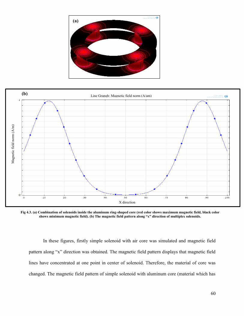
60
In these figures, firstly simple solenoid with air core was simulated and magnetic field
pattern along “x” direction was obtained. The magnetic field pattern displays that magnetic field
lines have concentrated at one point in center of solenoid. Therefore, the material of core was
changed. The magnetic field pattern of simple solenoid with aluminum core (material which has
Line Grapgh: Magnetic field norm (A/am)
Mag
net
ic f
ield
no
rm (
A/m
)
X direction
(a)
(b)
Fig 4.3. (a) Combination of solenoids inside the aluminum ring-shaped core (red color shows maximum magnetic field, black color
shows minimum magnetic field). (b) The magnetic field pattern along “x” direction of multiplex solenoids.
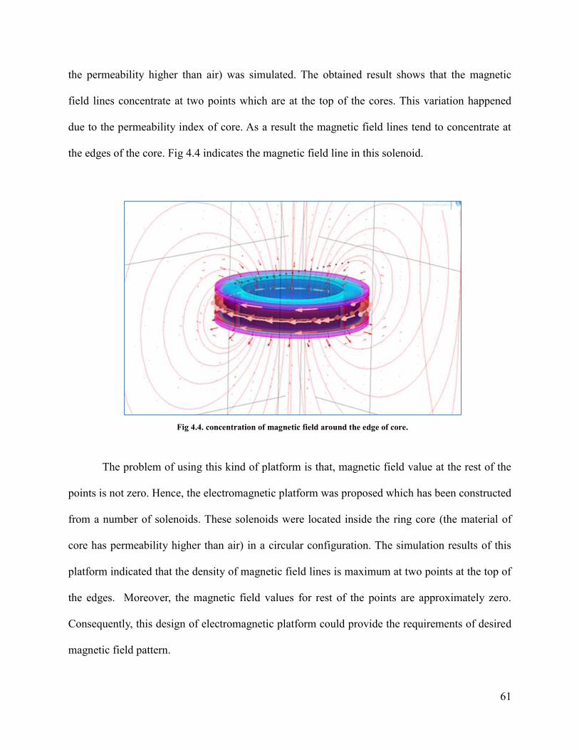
61
the permeability higher than air) was simulated. The obtained result shows that the magnetic
field lines concentrate at two points which are at the top of the cores. This variation happened
due to the permeability index of core. As a result the magnetic field lines tend to concentrate at
the edges of the core. Fig 4.4 indicates the magnetic field line in this solenoid.
The problem of using this kind of platform is that, magnetic field value at the rest of the
points is not zero. Hence, the electromagnetic platform was proposed which has been constructed
from a number of solenoids. These solenoids were located inside the ring core (the material of
core has permeability higher than air) in a circular configuration. The simulation results of this
platform indicated that the density of magnetic field lines is maximum at two points at the top of
the edges. Moreover, the magnetic field values for rest of the points are approximately zero.
Consequently, this design of electromagnetic platform could provide the requirements of desired
magnetic field pattern.
Fig 4.4. concentration of magnetic field around the edge of core.

62
4.1.2 Simulation Results for Improving the Homogeneity of Magnetic Field Pattern
One of the objectives of this study is the control on magnetic particles during the rotation
of microfluidic CD and performing the several biological assays simultaneously as well.
Therefore, to achieve this end, homogeneity of magnetic field pattern along the circle-shaped
area is essential. In order to improve the homogeneity of magnetic field pattern, the proposed
design of an electromagnetic platform was modified. As previously described, increasing the
number of solenoids leads to improving the homogeneity of magnetic field patter. Fig 4.5, 4.6,
4.7 shows the progress of improvement the homogeneity of the magnetic field pattern.
(a)
(b)
Fig 4.5. (a) Electromagnetic platform with 4 solenoids. (b) Magnetic field pattern of ring electromagnetic
platform with 4 solenoids.
Surface magnetic field norm (A/m) Contour: Magnetic field norm (A/m)

63
(a)
(b)
Fig 4.6. (a) Electromagnetic platform with 8 solenoids. (b) Magnetic field pattern of ring electromagnetic
platform with 8 solenoids.
Surface magnetic field norm (A/m) Contour: Magnetic field norm (A/m)

64
In electromagnetic platform with four solenoids, the magnetic field pattern shows the
magnetic field lines are concentrated on only four points. Increasing the number of solenoid to
eight creates more homogeneity in the magnetic field pattern. Lastly, the simulation result
indicates that magnetic field pattern in nearly homogenous for all point by increasing the number
of solenoids to 16. Fig 4.8 demonstrates the difference between these three patterns.
(b)
Fig 4.7. (a) Electromagnetic platform with 16 solenoids. (b) Magnetic field pattern of ring
electromagnetic platform with 16 solenoids.
(a)
Surface magnetic field norm (A/m) Contour: Magnetic field norm (A/m)
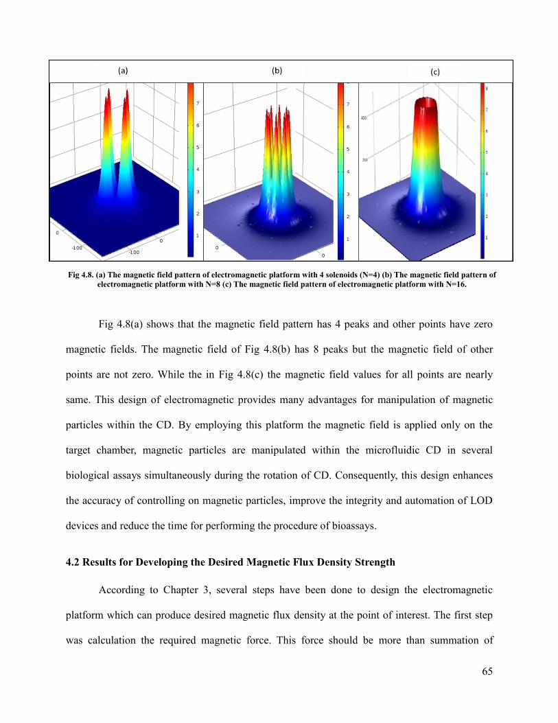
65
Fig 4.8(a) shows that the magnetic field pattern has 4 peaks and other points have zero
magnetic fields. The magnetic field of Fig 4.8(b) has 8 peaks but the magnetic field of other
points are not zero. While the in Fig 4.8(c) the magnetic field values for all points are nearly
same. This design of electromagnetic provides many advantages for manipulation of magnetic
particles within the CD. By employing this platform the magnetic field is applied only on the
target chamber, magnetic particles are manipulated within the microfluidic CD in several
biological assays simultaneously during the rotation of CD. Consequently, this design enhances
the accuracy of controlling on magnetic particles, improve the integrity and automation of LOD
devices and reduce the time for performing the procedure of bioassays.
4.2 Results for Developing the Desired Magnetic Flux Density Strength
According to Chapter 3, several steps have been done to design the electromagnetic
platform which can produce desired magnetic flux density at the point of interest. The first step
was calculation the required magnetic force. This force should be more than summation of
Fig 4.8. (a) The magnetic field pattern of electromagnetic platform with 4 solenoids (N=4) (b) The magnetic field pattern of
electromagnetic platform with N=8 (c) The magnetic field pattern of electromagnetic platform with N=16.
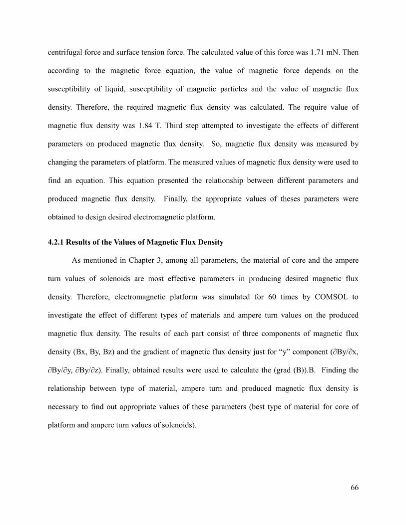
66
centrifugal force and surface tension force. The calculated value of this force was 1.71 mN. Then
according to the magnetic force equation, the value of magnetic force depends on the
susceptibility of liquid, susceptibility of magnetic particles and the value of magnetic flux
density. Therefore, the required magnetic flux density was calculated. The require value of
magnetic flux density was 1.84 T. Third step attempted to investigate the effects of different
parameters on produced magnetic flux density. So, magnetic flux density was measured by
changing the parameters of platform. The measured values of magnetic flux density were used to
find an equation. This equation presented the relationship between different parameters and
produced magnetic flux density. Finally, the appropriate values of theses parameters were
obtained to design desired electromagnetic platform.
4.2.1 Results of the Values of Magnetic Flux Density
As mentioned in Chapter 3, among all parameters, the material of core and the ampere
turn values of solenoids are most effective parameters in producing desired magnetic flux
density. Therefore, electromagnetic platform was simulated for 60 times by COMSOL to
investigate the effect of different types of materials and ampere turn values on the produced
magnetic flux density. The results of each part consist of three components of magnetic flux
density (Bx, By, Bz) and the gradient of magnetic flux density just for “y” component (∂By/∂x,
∂By/∂y, ∂By/∂z). Finally, obtained results were used to calculate the (grad (B)).B. Finding the
relationship between type of material, ampere turn and produced magnetic flux density is
necessary to find out appropriate values of these parameters (best type of material for core of
platform and ampere turn values of solenoids).
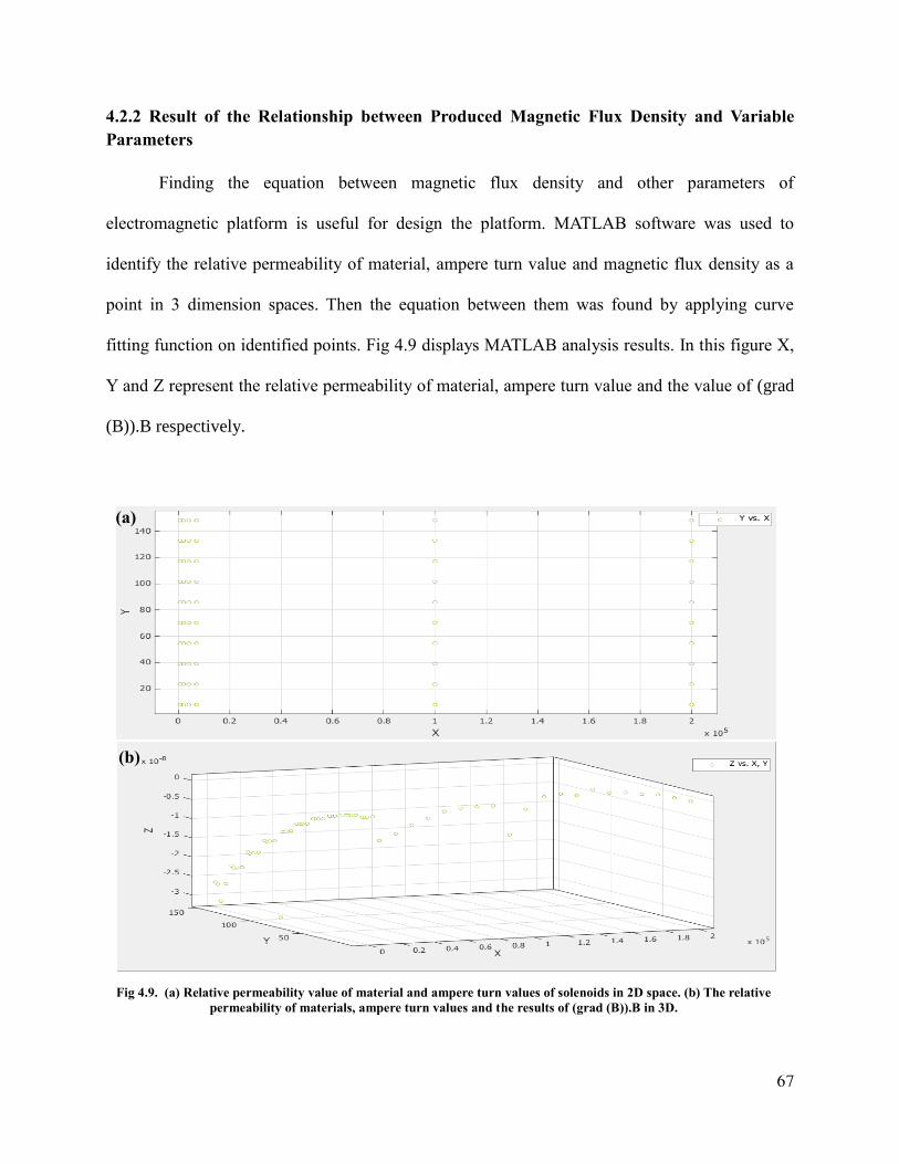
67
4.2.2 Result of the Relationship between Produced Magnetic Flux Density and Variable
Parameters
Finding the equation between magnetic flux density and other parameters of
electromagnetic platform is useful for design the platform. MATLAB software was used to
identify the relative permeability of material, ampere turn value and magnetic flux density as a
point in 3 dimension spaces. Then the equation between them was found by applying curve
fitting function on identified points. Fig 4.9 displays MATLAB analysis results. In this figure X,
Y and Z represent the relative permeability of material, ampere turn value and the value of (grad
(B)).B respectively.
(a)
(b)
Fig 4.9. (a) Relative permeability value of material and ampere turn values of solenoids in 2D space. (b) The relative
permeability of materials, ampere turn values and the results of (grad (B)).B in 3D.
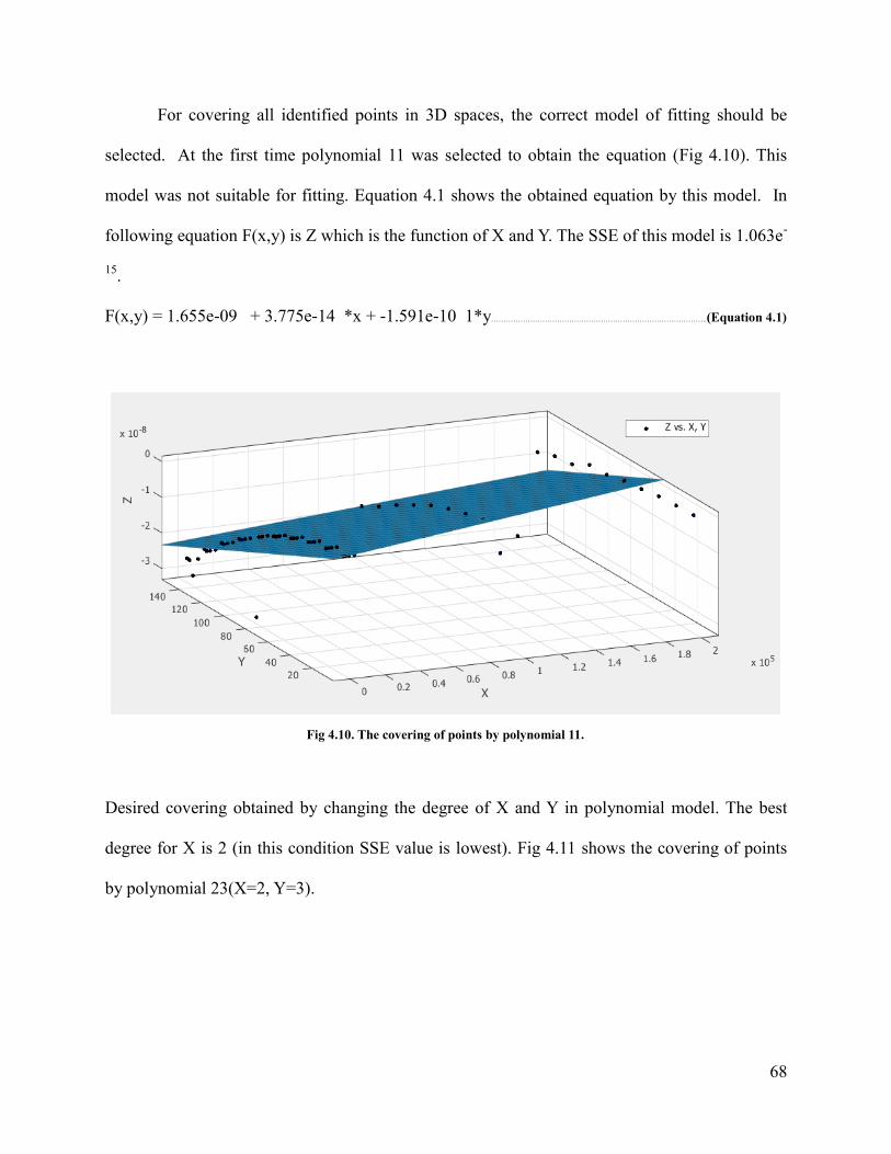
68
For covering all identified points in 3D spaces, the correct model of fitting should be
selected. At the first time polynomial 11 was selected to obtain the equation (Fig 4.10). This
model was not suitable for fitting. Equation 4.1 shows the obtained equation by this model. In
following equation F(x,y) is Z which is the function of X and Y. The SSE of this model is 1.063e-
15.
F(x,y) = 1.655e-09 + 3.775e-14 *x + -1.591e-10 1*y……………………………………………………………………………..(Equation 4.1)
Desired covering obtained by changing the degree of X and Y in polynomial model. The best
degree for X is 2 (in this condition SSE value is lowest). Fig 4.11 shows the covering of points
by polynomial 23(X=2, Y=3).
Fig 4.10. The covering of points by polynomial 11.
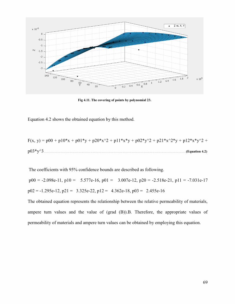
69
Equation 4.2 shows the obtained equation by this method.
F(x, y) = p00 + p10*x + p01*y + p20*x^2 + p11*x*y + p02*y^2 + p21*x^2*y + p12*x*y^2 +
p03*y^3……………………………………………………………………………………………………………………………………………………………………………………………………(Equation 4.2)
The coefficients with 95% confidence bounds are described as following.
p00 = -2.098e-11, p10 = 5.577e-16, p01 = 3.007e-12, p20 = -2.518e-21, p11 = -7.031e-17
p02 = -1.295e-12, p21 = 3.325e-22, p12 = 4.362e-18, p03 = 2.455e-16
The obtained equation represents the relationship between the relative permeability of materials,
ampere turn values and the value of (grad (B)).B. Therefore, the appropriate values of
permeability of materials and ampere turn values can be obtained by employing this equation.
Fig 4.11. The covering of points by polynomial 23.

70
4.2.3 Results of Appropriate Values for Permeability of Materials and Ampere-Turn of
Solenoids
The appropriate values of variable parameters (permeability of materials and ampere turn
values) can be gained by using MATLAB software. The first step is identifying the wide range of
values for these tow parameters in MATLAB. After identifying the ranges of inputs, the obtained
equation was employed to calculate the produced magnetic flux density at the point of interest.
Table 4.1 displays the results of this part. According to Table 4.1, material with relative
permeability 200000 can produce desired values of (grad (B)).B (i.e. (grad (B)).B > 1.9). As
mentioned in Chapter 3, this material is 99.95% purified iron. The availability to other materials
such as silicon iron is easier than this material. Hence, there are different methods to increase the
magnetic flux density of an electromagnetic platform when the other materials are chosen as a
core of platform. One of these methods is using a thin layer of ring permanent magnet on the
surface of electromagnetic platform. In this case, the value of produced magnetic flux density by
electromagnetic platform and permanent magnet should be 1.84 T.

71
Table 4.1. The appropriate values of relative permeability of materials and ampere-turn value.
Number Relative
permeability of materials
Ampere turn values
of solenoids (grad (B)).B Number
Relative permeability of materials
Ampere turn values
of solenoids (grad (B)).B
1 650 78 -4.78E-07 31 8000 78 0.11741
2 650 234 -4.77E-07 32 8000 234 0.117415
3 650 390 -4.77E-07 33 8000 390 0.117419
4 650 546 -4.77E-07 34 8000 546 0.117423
5 650 702 -4.77E-07 35 8000 702 0.117428
6 650 858 -4.76E-07 36 8000 858 0.117432
7 650 1014 -4.76E-07 37 8000 1014 0.117437
8 650 1170 -4.76E-07 38 8000 1170 0.117441
9 650 1326 -4.75E-07 39 8000 1326 0.117445
10 650 1482 -4.75E-07 40 8000 1482 0.11745
11 2000 78 -3.21E-06 41 100000 78 0.232554
12 2000 234 -3.21E-06 42 100000 234 0.232561
13 2000 390 -3.20E-06 43 100000 390 0.232567
14 2000 546 -3.20E-06 44 100000 546 0.232574
15 2000 702 -3.20E-06 45 100000 702 0.232581
16 2000 858 -3.20E-06 46 100000 858 0.232588
17 2000 1014 -3.19E-06 47 100000 1014 0.232595
18 2000 1170 -3.19E-06 48 100000 1170 0.232601
19 2000 1326 -3.19E-06 49 100000 1326 0.232608
20 2000 1482 -3.18E-06 50 100000 1482 0.232615
21 4000 78 -4.99E-06 51 200000 78 1.912214
22 4000 234 -4.98E-06 52 200000 234 1.912241
23 4000 390 -4.97E-06 53 200000 390 1.912269
24 4000 546 -4.96E-06 54 200000 546 1.912296
25 4000 702 -4.95E-06 55 200000 702 1.912323
26 4000 858 -4.94E-06 56 200000 858 1.91235
27 4000 1014 -4.93E-06 57 200000 1014 1.912378
28 4000 1170 -4.91E-06 58 200000 1170 1.912405
29 4000 1326 -4.90E-06 59 200000 1326 1.912432
30 4000 1482 -4.89E-06 60 200000 1482 1.912459
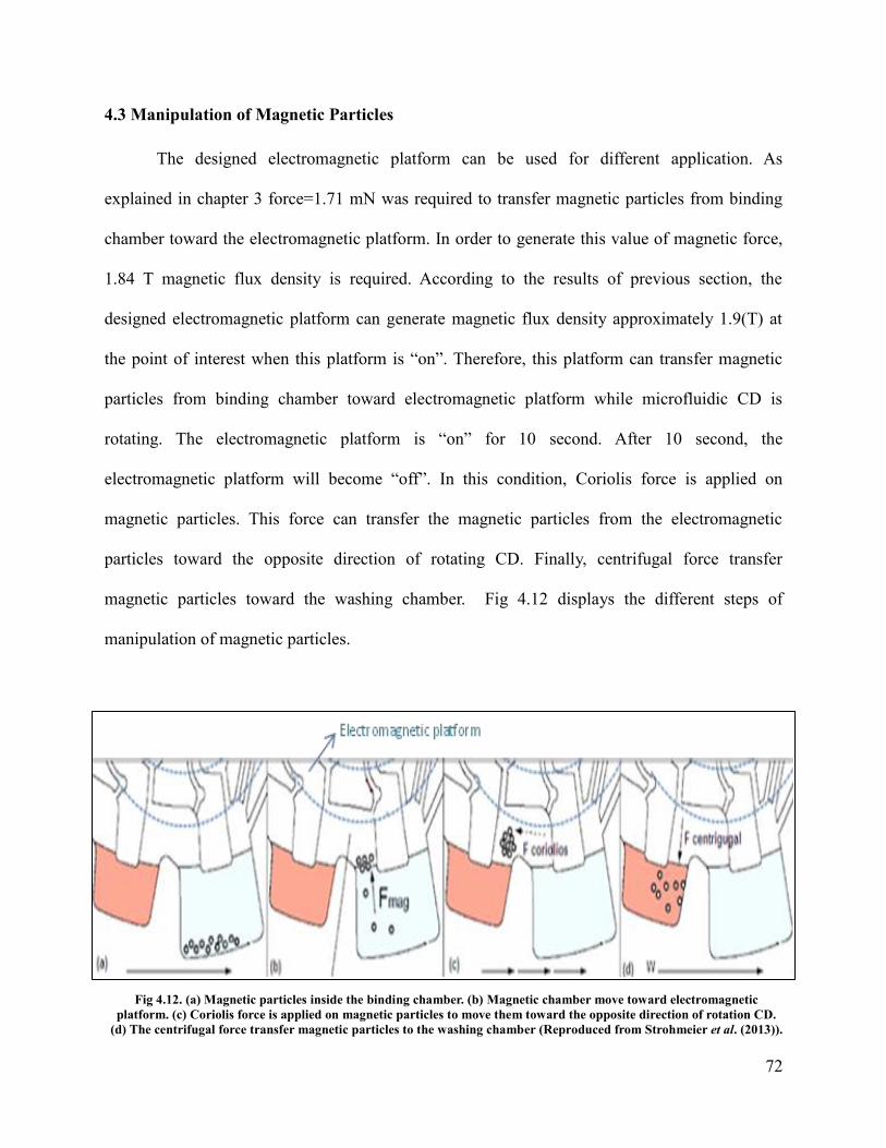
72
4.3 Manipulation of Magnetic Particles
The designed electromagnetic platform can be used for different application. As
explained in chapter 3 force=1.71 mN was required to transfer magnetic particles from binding
chamber toward the electromagnetic platform. In order to generate this value of magnetic force,
1.84 T magnetic flux density is required. According to the results of previous section, the
designed electromagnetic platform can generate magnetic flux density approximately 1.9(T) at
the point of interest when this platform is “on”. Therefore, this platform can transfer magnetic
particles from binding chamber toward electromagnetic platform while microfluidic CD is
rotating. The electromagnetic platform is “on” for 10 second. After 10 second, the
electromagnetic platform will become “off”. In this condition, Coriolis force is applied on
magnetic particles. This force can transfer the magnetic particles from the electromagnetic
particles toward the opposite direction of rotating CD. Finally, centrifugal force transfer
magnetic particles toward the washing chamber. Fig 4.12 displays the different steps of
manipulation of magnetic particles.
Fig 4.12. (a) Magnetic particles inside the binding chamber. (b) Magnetic chamber move toward electromagnetic
platform. (c) Coriolis force is applied on magnetic particles to move them toward the opposite direction of rotation CD.
(d) The centrifugal force transfer magnetic particles to the washing chamber (Reproduced from Strohmeier et al. (2013)).
73
Chapter 5. CONCLUSION AND RECOMMENDATION FOR FUTURE WORK
5.1 Conclusion
In this study, an electromagnetic platform for controlling magnetic particles in a
centrifugal microfluidic platform is designed and simulated. The dimensions of electromagnetic
platform have been selected based on the design of microfluidic CD which provided by
(Strohmeier et al., 2013) for DNA purification. Then geometrical shape of electromagnetic
platform has been designed based on producing the magnetic field pattern with three features
including; symmetrical shape of magnetic field pattern relative to the z axis, the maximum
magnetic field strength at the specific locations and finally homogeneity of produced magnetic
field pattern above electromagnetic platform. Magnetic field pattern which have these three
features is called desired magnetic field pattern. In order to obtain desired magnetic field pattern,
an electromagnetic platform has been designed. This platform consists of the circular-shaped
core with 16 solenoids.
The value of produced magnetic flux density is another objective of this study. So as to
obtain the required magnetic flux density, the following procedures have been done. At the first
place, the required magnetic force for transporting magnetic particles has been calculated. The
value of the required magnetic force should be more than the summation of centrifugal force and
surface tension force which are applied at the opposite direction of magnetic force. At the second
place, required magnetic flux density has been calculated by employing the magnetic force
equation. Then, the effects of structural parameters of electromagnetic platform on producing
magnetic flux density have been investigated. The value of some of these parameters should be
considered constant such as the axial and radial distance between magnetic particles and
electromagnetic platform. While other parameters can be considered as variables including the
74
type of material which is used as a core of platform and ampere turn of solenoid. The effects of
these two parameters on produced magnetic flux density have been investigated by COMSOL
software. Electromagnetic platform has been simulated for 60 times to obtain magnitude and
gradient of magnetic flux density when the variable parameters were changed. The obtained
results have been used to find the relationship between variable parameters and produced
magnetic flux density. The equation of these parameters has been obtained by employing the
curve fitting function in MATLAB software. This equation is general for designed
electromagnetic platform. The wide ranges of variable parameters have been identified as inputs.
Finally, appropriate values of variable parameters have been gained by employing obtained
equation to design the desired electromagnetic platform. This procedure can be used in different
conditions such as, changing the rotational speed of microfluidic CD or changing the size or
susceptibility of magnetic particles. The electromagnetic platform with purified iron as a material
of core and different ranges of ampere turn values can produced desired value of magnetic flux
density at the location of magnetic particles. The magnetic force caused by the designed
electromagnetic platform can overcome the centrifugal force and surface tension force. As a
result, magnetic particles are transferred toward the electromagnetic platform when this platform
is “on”. The electromagnetic platform is “on” for 10 seconds and then it will be “off”. When
electromagnetic platform is “off”, magnetic particles are transferred toward washing chamber by
the effect of Coriolis force and centrifugal force.

75
5.2 Limitations and Recommendation for Future Work
Accessibility of purified iron is less than other material such as, silicon iron. There are
variety methods to produce desired magnetic flux density value by using other types of materials.
One of the methods is using thin layer of ring permanent magnet on the surface of
electromagnetic platform.
Designed electromagnetic platform has been used for different applications such as DNA
purification. This platform can be used for other applications such as, different types of sandwich
immunoassay. In these assays washing step is used for presenting the target in a measurable
form. This step requires the additional chambers on the LOD platform for storage the washing
liquid. In addition, mechanical actuation of washing liquid is time consuming process. In the
magnetic particles-based assays, employing magnetic field facilitates the washing step. As
mentioned earlier these types of assays are based on labelling analyte with magnetic particles.
Thus magnetic field acts as washing solution to remove the analyte which have a weak bind with
immobilized specific antibodies. Therefore, washing chambers were eliminated in the design of
LOD platform. On the other hand, detection chambers are required in immunoassay to measure
target (analyte). The antibodies should be immobilised on the surface of detection chamber. So,
magnetic field can be used in this chamber for binding the analyte and immobilized antibodies.
As a result, the design of CD for sandwich immunoassay can be included only four chambers
namely; sample chamber, mixing chamber, waste chamber and detection chamber.
76
REFERENCES
Alqadi, M. K., Alzoubi, F. Y., Al-Khateeb, H. M., & Ayoub, N. Y. (2008). Calculation of levitation force between
small superconducting cylinder and magnetic ring in the critical state. Journal of superconductivity and novel
magnetism, 21(7), 415-419.
Aytur, T. S. (2007). A CMOS biosensor for infectious disease detection. ProQuest.
Babic, S. I., & Akyel, C. (2008). Improvement in the analytical calculation of the magnetic field produced by
permanent magnet rings. Progress In Electromagnetics Research C, 5, 71-82.
Bekinal, S. I., Anil, T. R., & Jana, S. (2012). ANALYSIS OF AXIALLY MAGNETIZED PERMANENT MAGNET
BEARING CHARACTERISTICS.Progress In Electromagnetics Research B, 43.
Bruls, D. M., Evers, T. H., Kahlman, J. A. H., Van Lankvelt, P. J. W., Ovsyanko, M., Pelssers, E. G. M., ... & Prins,
M. W. J. (2009). Rapid integrated biosensor for multiplexed immunoassays based on actuated magnetic
nanoparticles. Lab on a Chip, 9(24), 3504-3510.
Burger, R., Kirby, D., Glynn, M., Nwankire, C., O'Sullivan, M., Siegrist, J., ... & Ducrée, J. (2012). Centrifugal
microfluidics for cell analysis. Current opinion in chemical biology, 16(3), 409-414
Chen, C. L., Chen, K. C., Pan, Y. C., Lee, T. P., Hsiung, L. C., Lin, C. M., ... & Wo, A. M. (2011). Separation and
detection of rare cells in a microfluidic disk via negative selection. Lab on a Chip, 11(3), 474-483.
Chen, K. C., Lee, T. P., Pan, Y. C., Chiang, C. L., Chen, C. L., Yang, Y. H., ... & Wo, A. M. (2011). Detection of
circulating endothelial cells via a microfluidic disk. Clinical chemistry, 57(4), 586-592.
Cheng, D. K. (1989). Field and wave electromagnetics (Vol. 2). New York: Addison-Wesley.
Delfino, F., Manella, A., Molfino, P., & Rossi, M. (2001). Numerical calculation of total force upon permanent
magnets using equivalent source methods.COMPEL: The International Journal for Computation and Mathematics in
Electrical and Electronic Engineering, 20(2), 431-447.
Delinchant, B., Wurtz, F., Yonnet, J. P., & Coulomb, J. L. (2011). Interaction between ring-shaped permanent
magnets with symbolic gradients: application to magnetic bearing system optimization. Magnetics, IEEE
Transactions on,47(5), 1418-1421.
Ducrée, J., Haeberle, S., Lutz, S., Pausch, S., Von Stetten, F., & Zengerle, R. (2007). The centrifugal microfluidic
bio-disk platform. Journal of Micromechanics and Microengineering, 17(7), S103.
Gijs, M. A. (2004). Magnetic bead handling on-chip: new opportunities for analytical applications. Microfluidics
and Nanofluidics, 1(1), 22-40.
Glasgow, I., & Aubry, N. (2003). Enhancement of microfluidic mixing using time pulsing. Lab on a Chip, 3(2), 114-
120.
Grumann, M., Geipel, A., Riegger, L., Zengerle, R., & Ducrée, J. (2005). Batch-mode mixing on centrifugal
microfluidic platforms. Lab on a Chip, 5(5), 560-565.
Kido, H., Micic, M., Smith, D., Zoval, J., Norton, J., & Madou, M. (2007). A novel, compact disk-like centrifugal
microfluidics system for cell lysis and sample homogenization. Colloids and Surfaces B: Biointerfaces, 58(1), 44-
51.
Kim, J., Kido, H., Rangel, R. H., & Madou, M. J. (2008). Passive flow switching valves on a centrifugal
microfluidic platform. Sensors and actuators B: Chemical, 128(2), 613-621.
77
Kirby, D., Siegrist, J., Kijanka, G., Zavattoni, L., Sheils, O., O’Leary, J., ... & Ducrée, J. (2012). Centrifugo-
magnetophoretic particle separation. Microfluidics and nanofluidics, 13(6), 899-908.
Kosek, M., Mikolanda, T., & Richter, A. EFFECTIVE AND ROBUST CALCULATION OF MAGNETIC FORCE.
Lai, S., Wang, S., Luo, J., Lee, L. J., Yang, S. T., & Madou, M. J. (2004). Design of a compact disk-like microfluidic
platform for enzyme-linked immunosorbent assay. Analytical chemistry, 76(7), 1832-1837.
Lee, C. S., Lee, H., & Westervelt, R. M. (2001). Microelectromagnets for the control of magnetic nanoparticles. Applied physics letters, 79(20), 3308-3310.
Madou, M. J., Lee, L. J., Daunert, S., Lai, S., & Shih, C. H. (2001). Design and fabrication of CD-like microfluidic
platforms for diagnostics: microfluidic functions. Biomedical Microdevices, 3(3), 245-254.
Madou, M., Zoval, J., Jia, G., Kido, H., Kim, J., & Kim, N. (2006). Lab on a CD.Annu. Rev. Biomed. Eng., 8, 601-
628.
Rakotoarison, H. L., Delinchant, B., & Cugat, O. (2006, May). Methodology and tool for generating semi-analytical
models used to pre-design electromagnetic MEMS (Mag-MEMS). In Electromagnetic Field Computation, 2006 12th
Biennial IEEE Conference on (pp. 444-444). IEEE.
Ravaud, R., Lemarquand, G., Lemarquand, V., & Depollier, C. (2008). Analytical calculation of the magnetic field
created by permanent-magnet rings.Magnetics, IEEE Transactions on, 44(8), 1982-1989.
Ravaud, R., Lemarquand, G., Lemarquand, V., & Depollier, C. (2009). Discussion about the analytical calculation of
the magnetic field created by permanent magnets. Progress In Electromagnetics Research B, 11, 281-297.
Ravaud, R., Lemarquand, G., & Lemarquand, V. (2009). Force and stiffness of passive magnetic bearings using
permanent magnets. Part 1: Axial magnetization. Magnetics, IEEE Transactions on, 45(7), 2996-3002.
Ravaud, R., Lemarquand, G., & Lemarquand, V. (2010). Halbach structures for permanent magnets
bearings. Progress In Electromagnetics Research M, 14, 263-277.
Robertson, W., Cazzolato, B., & Zander, A. (2012). Axial Force Between a Thick Coil and a Cylindrical Permanent
Magnet: Optimizing the Geometry of an Electromagnetic Actuator. Magnetics, IEEE Transactions on, 48(9), 2479-
2487.
Siegrist, J., Burger, R., Kirby, D., Zavattoni, L., Kijanka, G., & Ducrée, J. (2011, October). Stress-free
centrifugomagnetic 2D-separation of cancer cells in a stopped-flow mode. In 15th International Conference on
Miniaturized Systems for Chemistry and Life Sciences (uTAS). Seattle, USA (pp. 2-6).
Strohmeier, O., Emperle, A., Roth, G., Mark, D., Zengerle, R., & von Stetten, F. (2013). Centrifugal gas-phase
transition magnetophoresis (GTM)–a generic method for automation of magnetic bead based assays on the
centrifugal microfluidic platform and application to DNA purification. Lab on a Chip, 13(1), 146-155.
Thio, T. H. G., Ibrahim, F., Al-Faqheri, W., Moebius, J., Khalid, N. S., Soin, N., ... & Madou, M. (2013). Push pull
microfluidics on a multi-level 3D CD. Lab on a Chip, 13(16), 3199-3209.
Verpoorte, E., & de Rooij, N. F. (2003). Microfluidics meets MEMS.Proceedings of the IEEE, 91(6), 930-
953.Wadle, S., Strohmeier, O., Rombach, M., Mark, D., Zengerle, R., & von Stetten, F. LABDISK INTEGRATED
DNA EXTRACTION FROM WHOLE BLOOD USING MAGNETIC PARTICLES.
Williams, M. D., Zito, J. C., Agashe, J., Sopeju, A., & Arnold, D. P. (2008). Design of an electrodynamically
actuated microvalve using COMSOL multiphysics and MATLAB. In Excerpt from the Proceedings of the COMSOL
Conference.

78
Wirix-Speetjens, R., Fyen, W., Xu, K., De Boeck, J., & Borghs, G. (2005). A force study of on-chip
magnetic particle transport based on tapered conductors.Magnetics, IEEE Transactions on, 41(10), 4128-
4133.
Yusoff, N. A., Soin, N., & Ibrahim, F. (2009, October). Lab-on-a-disk as a potential microfluidic platform for dengue
NS1-ELISA. In Industrial Electronics & Applications, 2009. ISIEA 2009. IEEE Symposium on (Vol. 2, pp. 946-
950). IEEE.