Control of Foaming in Amine Systems - MPR Services Inc
13
D-Foam Incorporated, P.O. Box 1393, MPR Services, Inc., 1201 FM646, Weatherford, TX, 76086-1393, USA Dickinson, TX 77539-3014, USA Telephone +1 817-304-2729 www.D-Foam.com +1 281 337-7424 www.mprservices.com Control of Foaming in Amine Systems Stephen A. von Phul D-Foam, Incorporated P.O. Box 1393 Weatherford, TX 76086 [email protected] 817-304-2729 Arthur L. Cummings, Ph.D. (Presenter) MPR Services, Inc. 1201 FM 646 Dickinson, TX 77539 [email protected] 281-337-7424 x 108 ABSTRACT Amine solutions foam. Solution foaming causes plant upsets. It is the “disengagement”, or break time that differentiates normal, desirable froth from undesirable foam. Plant upsets due to foaming require immediate mitigating actions. A variety of solution contaminants and operating conditions can cause froth to stabilize into foam. Mitigating actions include adding chemical antifoaming agents, altering operating conditions, and removing foam causative agents. A series of typical amine foaming incidents, causes, and plant responses are presented. The upsets and responses are explained in terms of root causative agents. This paper explains how removing the contaminants that stabilize the froth into foam is the only efficient way to control amine system foaming. Copyright © 2007 MPR Services, Inc., Dickinson, Texas, USA
Transcript of Control of Foaming in Amine Systems - MPR Services Inc

D-Foam Incorporated, P.O. Box 1393, MPR Services, Inc., 1201 FM646,
Weatherford, TX, 76086-1393, USA Dickinson, TX 77539-3014, USA Telephone +1 817-304-2729 www.D-Foam.com +1 281 337-7424 www.mprservices.com
Control of Foaming in Amine Systems
Stephen A. von Phul
D-Foam, Incorporated
P.O. Box 1393
Weatherford, TX 76086
817-304-2729
Arthur L. Cummings, Ph.D. (Presenter)
MPR Services, Inc.
1201 FM 646
Dickinson, TX 77539
281-337-7424 x 108
ABSTRACT
Amine solutions foam. Solution foaming causes plant upsets. It is the “disengagement”,
or break time that differentiates normal, desirable froth from undesirable foam. Plant
upsets due to foaming require immediate mitigating actions. A variety of solution
contaminants and operating conditions can cause froth to stabilize into foam. Mitigating
actions include adding chemical antifoaming agents, altering operating conditions, and
removing foam causative agents. A series of typical amine foaming incidents, causes,
and plant responses are presented. The upsets and responses are explained in terms of
root causative agents. This paper explains how removing the contaminants that stabilize
the froth into foam is the only efficient way to control amine system foaming.
Copyright © 2007 MPR Services, Inc., Dickinson, Texas, USA
D-Foam Incorporated, P.O. Box 1393, MPR Services, Inc., 1201 FM646
Weatherford, TX, 76086-1393, USA Dickinson, TX 77539-3014, USA Telephone +1 817-304-2729 www.D-Foam.com +1 281-337-7424 www.mprservices.com
2
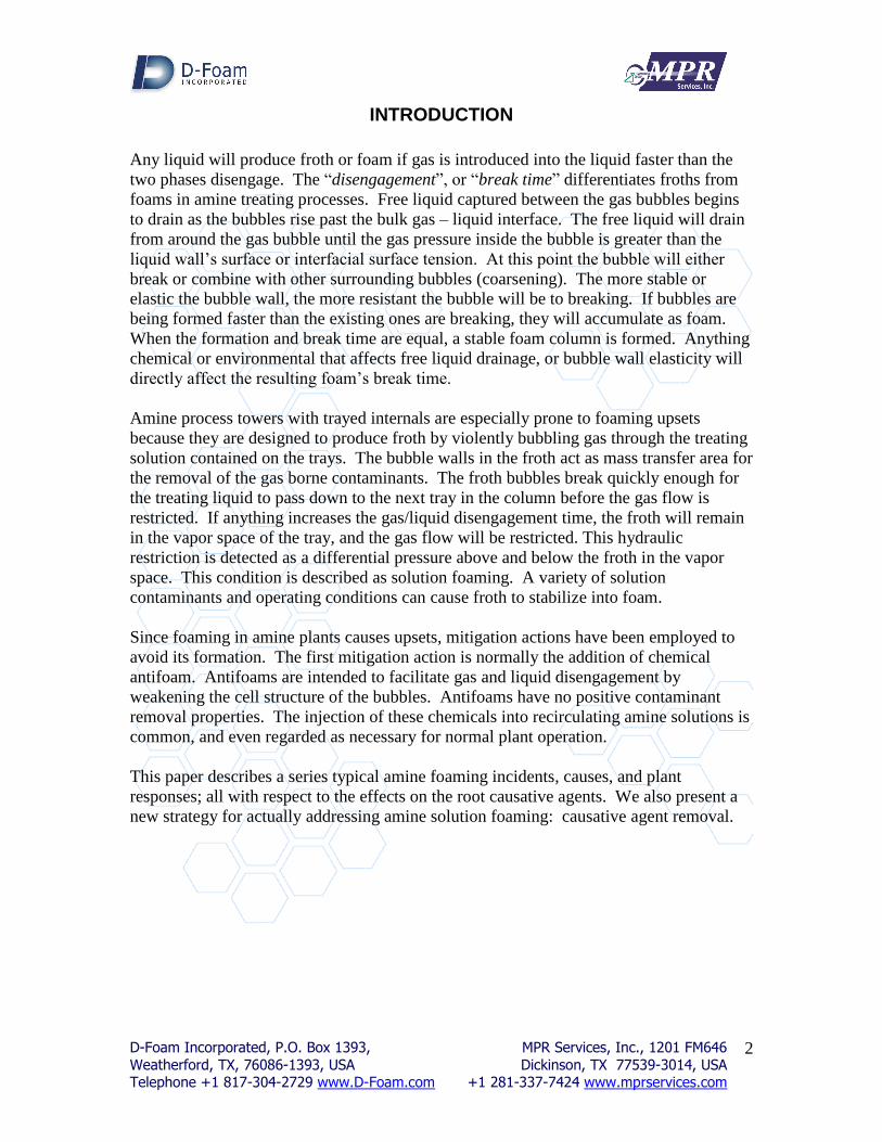
INTRODUCTION
Any liquid will produce froth or foam if gas is introduced into the liquid faster than the
two phases disengage. The “disengagement”, or “break time” differentiates froths from
foams in amine treating processes. Free liquid captured between the gas bubbles begins
to drain as the bubbles rise past the bulk gas – liquid interface. The free liquid will drain
from around the gas bubble until the gas pressure inside the bubble is greater than the
liquid wall’s surface or interfacial surface tension. At this point the bubble will either
break or combine with other surrounding bubbles (coarsening). The more stable or
elastic the bubble wall, the more resistant the bubble will be to breaking. If bubbles are
being formed faster than the existing ones are breaking, they will accumulate as foam.
When the formation and break time are equal, a stable foam column is formed. Anything
chemical or environmental that affects free liquid drainage, or bubble wall elasticity will
directly affect the resulting foam’s break time.
Amine process towers with trayed internals are especially prone to foaming upsets
because they are designed to produce froth by violently bubbling gas through the treating
solution contained on the trays. The bubble walls in the froth act as mass transfer area for
the removal of the gas borne contaminants. The froth bubbles break quickly enough for
the treating liquid to pass down to the next tray in the column before the gas flow is
restricted. If anything increases the gas/liquid disengagement time, the froth will remain
in the vapor space of the tray, and the gas flow will be restricted. This hydraulic
restriction is detected as a differential pressure above and below the froth in the vapor
space. This condition is described as solution foaming. A variety of solution
contaminants and operating conditions can cause froth to stabilize into foam.
Since foaming in amine plants causes upsets, mitigation actions have been employed to
avoid its formation. The first mitigation action is normally the addition of chemical
antifoam. Antifoams are intended to facilitate gas and liquid disengagement by
weakening the cell structure of the bubbles. Antifoams have no positive contaminant
removal properties. The injection of these chemicals into recirculating amine solutions is
common, and even regarded as necessary for normal plant operation.
This paper describes a series typical amine foaming incidents, causes, and plant
responses; all with respect to the effects on the root causative agents. We also present a
new strategy for actually addressing amine solution foaming: causative agent removal.
D-Foam Incorporated, P.O. Box 1393, MPR Services, Inc., 1201 FM646
Weatherford, TX, 76086-1393, USA Dickinson, TX 77539-3014, USA Telephone +1 817-304-2729 www.D-Foam.com +1 281-337-7424 www.mprservices.com
3
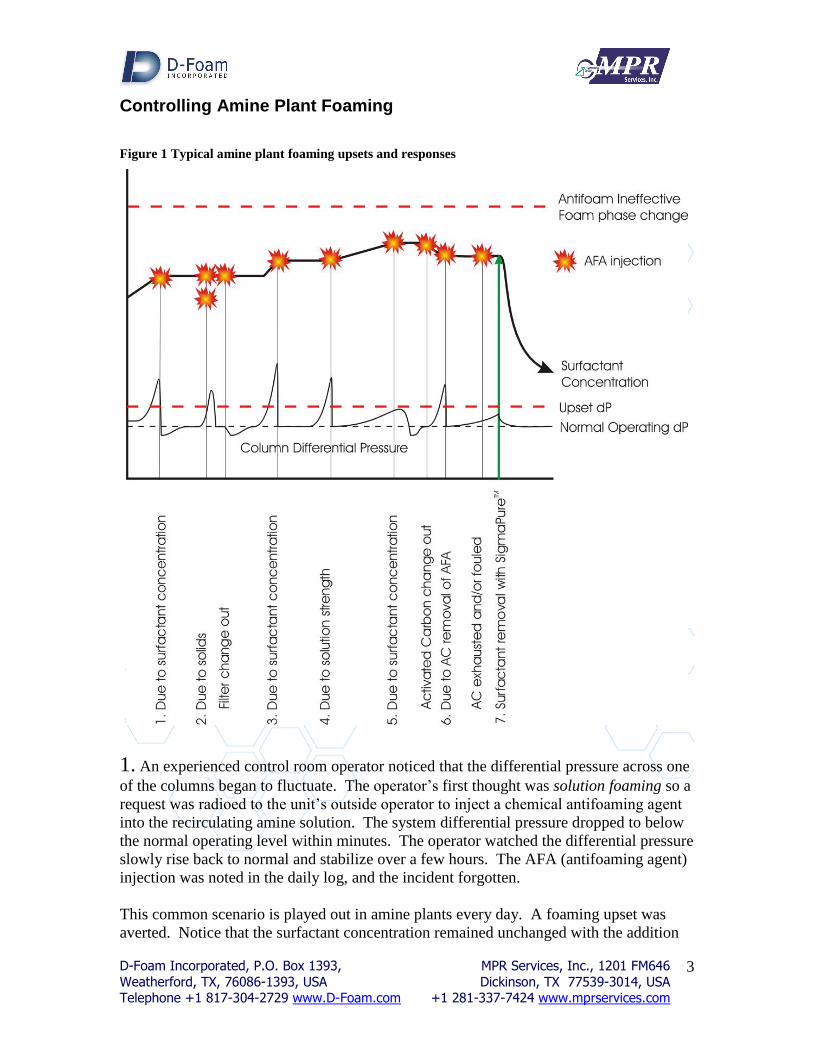
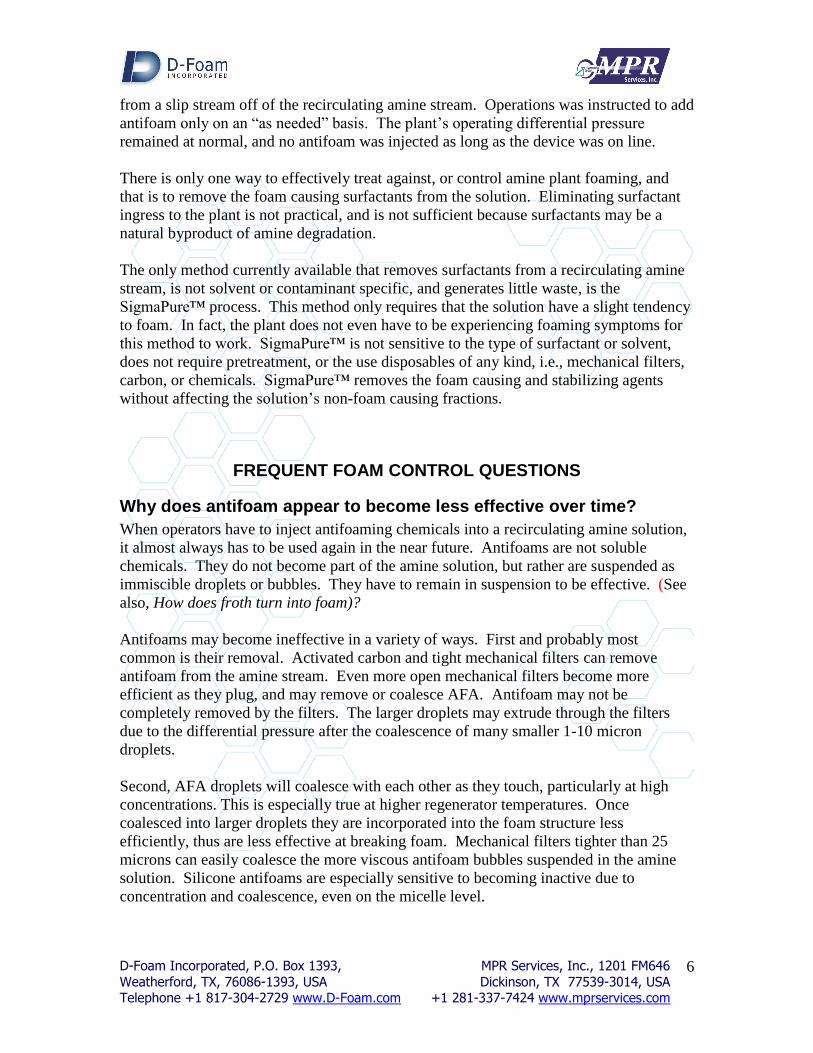
Controlling Amine Plant Foaming
Figure 1 Typical amine plant foaming upsets and responses
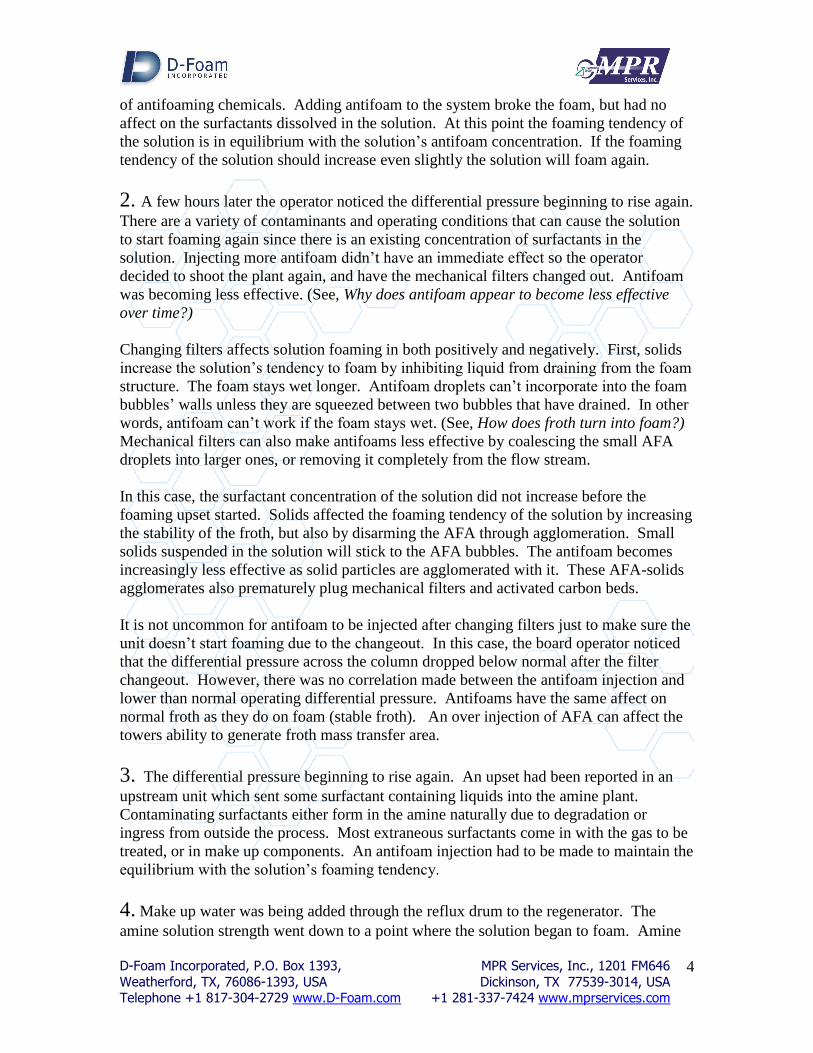
1. An experienced control room operator noticed that the differential pressure across one
of the columns began to fluctuate. The operator’s first thought was solution foaming so a
request was radioed to the unit’s outside operator to inject a chemical antifoaming agent
into the recirculating amine solution. The system differential pressure dropped to below
the normal operating level within minutes. The operator watched the differential pressure
slowly rise back to normal and stabilize over a few hours. The AFA (antifoaming agent)
injection was noted in the daily log, and the incident forgotten.
This common scenario is played out in amine plants every day. A foaming upset was
averted. Notice that the surfactant concentration remained unchanged with the addition
D-Foam Incorporated, P.O. Box 1393, MPR Services, Inc., 1201 FM646
Weatherford, TX, 76086-1393, USA Dickinson, TX 77539-3014, USA Telephone +1 817-304-2729 www.D-Foam.com +1 281-337-7424 www.mprservices.com
4
of antifoaming chemicals. Adding antifoam to the system broke the foam, but had no
affect on the surfactants dissolved in the solution. At this point the foaming tendency of
the solution is in equilibrium with the solution’s antifoam concentration. If the foaming
tendency of the solution should increase even slightly the solution will foam again.
2. A few hours later the operator noticed the differential pressure beginning to rise again.
There are a variety of contaminants and operating conditions that can cause the solution
to start foaming again since there is an existing concentration of surfactants in the
solution. Injecting more antifoam didn’t have an immediate effect so the operator
decided to shoot the plant again, and have the mechanical filters changed out. Antifoam
was becoming less effective. (See, Why does antifoam appear to become less effective
over time?)
Changing filters affects solution foaming in both positively and negatively. First, solids
increase the solution’s tendency to foam by inhibiting liquid from draining from the foam
structure. The foam stays wet longer. Antifoam droplets can’t incorporate into the foam
bubbles’ walls unless they are squeezed between two bubbles that have drained. In other
words, antifoam can’t work if the foam stays wet. (See, How does froth turn into foam?)
Mechanical filters can also make antifoams less effective by coalescing the small AFA
droplets into larger ones, or removing it completely from the flow stream.
In this case, the surfactant concentration of the solution did not increase before the
foaming upset started. Solids affected the foaming tendency of the solution by increasing
the stability of the froth, but also by disarming the AFA through agglomeration. Small
solids suspended in the solution will stick to the AFA bubbles. The antifoam becomes
increasingly less effective as solid particles are agglomerated with it. These AFA-solids
agglomerates also prematurely plug mechanical filters and activated carbon beds.
It is not uncommon for antifoam to be injected after changing filters just to make sure the
unit doesn’t start foaming due to the changeout. In this case, the board operator noticed
that the differential pressure across the column dropped below normal after the filter
changeout. However, there was no correlation made between the antifoam injection and
lower than normal operating differential pressure. Antifoams have the same affect on
normal froth as they do on foam (stable froth). An over injection of AFA can affect the
towers ability to generate froth mass transfer area.
3. The differential pressure beginning to rise again. An upset had been reported in an
upstream unit which sent some surfactant containing liquids into the amine plant.
Contaminating surfactants either form in the amine naturally due to degradation or
ingress from outside the process. Most extraneous surfactants come in with the gas to be
treated, or in make up components. An antifoam injection had to be made to maintain the
equilibrium with the solution’s foaming tendency.
4. Make up water was being added through the reflux drum to the regenerator. The
amine solution strength went down to a point where the solution began to foam. Amine
D-Foam Incorporated, P.O. Box 1393, MPR Services, Inc., 1201 FM646
Weatherford, TX, 76086-1393, USA Dickinson, TX 77539-3014, USA Telephone +1 817-304-2729 www.D-Foam.com +1 281-337-7424 www.mprservices.com
5
solution strength appears to affect foaming in two ways. Lower strength solutions have
higher surface tensions which do not favor foaming. However, higher water content can
increase the solution solvency which can increase its surfactant concentration which
favors foaming. Foaming due to higher water concentration normally involves a second
less soluble contaminant that contains surfactants, like some liquid hydrocarbons. The
insoluble fraction of the hydrocarbon acts like a weak antifoam. Any amine soluble
fractions in the contaminating hydrocarbon increase the solution’s surfactant
concentration.
Higher strength solutions have higher viscosities which inhibit foam drainage, and
therefore favor foaming.
5. The solution’s surfactant concentration was slowly increasing naturally, but was now
accelerated due to the hydrocarbon ingress from the upstream process upset. The
equilibrium between the foam causing surfactants and the foam breaking antifoam was
imbalanced, so another AFA shot had to be made.
6. Lab analyses confirmed the presence of liquid hydrocarbon contamination. The
activated carbon obviously needed to be changed out. Like mechanical filters changes,
some plants have learned to inject AFA after a carbon change out. Shortly after the
activated carbon changeout, the differential pressure started to rise again.
Activated carbon is a remarkable substance. Its primary purpose in most non-amine
process applications is to adsorb dissolved organic molecules. Its use in treating amine
solutions should be no different. It is also generally used in a fixed bed format. Like
most fixed bed media; i.e., catalysts, sand, ion exchange, etc., activated carbon is
notoriously good at mechanically removing particles; including bubbles of insoluble
antifoam and antifoam-solids agglomerates. In this case, the activated carbon removed a
small amount of antifoam, so the solution began to foam again. It could also have been
that the bed wasn’t rinsed well enough, and small carbon solids agglomerated enough of
the antifoam to create the imbalance in foaming equilibrium, or the fine carbon particles
collected in the froth, stabilizing it into foam. It may have been a combination of all
three.
Many of the surfactants that cause foaming in amine solutions are adsorbed by activated
carbon. However, many are not. Activated carbon prefers some organics more than
others, and will adsorb one species until something it likes better comes along. It is
known to selectively desorb previously adsorbed compounds when this happens. This
fact makes activated carbon a good general solution maintenance device, but not reliable
for controlling amine solution foaming.
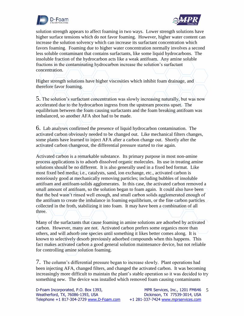
7. The column’s differential pressure began to increase slowly. Plant operations had
been injecting AFA, changed filters, and changed the activated carbon. It was becoming
increasingly more difficult to maintain the plant’s stable operation so it was decided to try
something new. The device was installed which removed foam causing contaminants
D-Foam Incorporated, P.O. Box 1393, MPR Services, Inc., 1201 FM646
Weatherford, TX, 76086-1393, USA Dickinson, TX 77539-3014, USA Telephone +1 817-304-2729 www.D-Foam.com +1 281-337-7424 www.mprservices.com
6
from a slip stream off of the recirculating amine stream. Operations was instructed to add
antifoam only on an “as needed” basis. The plant’s operating differential pressure
remained at normal, and no antifoam was injected as long as the device was on line.
There is only one way to effectively treat against, or control amine plant foaming, and
that is to remove the foam causing surfactants from the solution. Eliminating surfactant
ingress to the plant is not practical, and is not sufficient because surfactants may be a
natural byproduct of amine degradation.
The only method currently available that removes surfactants from a recirculating amine
stream, is not solvent or contaminant specific, and generates little waste, is the
SigmaPure™ process. This method only requires that the solution have a slight tendency
to foam. In fact, the plant does not even have to be experiencing foaming symptoms for
this method to work. SigmaPure™ is not sensitive to the type of surfactant or solvent,
does not require pretreatment, or the use disposables of any kind, i.e., mechanical filters,
carbon, or chemicals. SigmaPure™ removes the foam causing and stabilizing agents
without affecting the solution’s non-foam causing fractions.
FREQUENT FOAM CONTROL QUESTIONS
Why does antifoam appear to become less effective over time?
When operators have to inject antifoaming chemicals into a recirculating amine solution,
it almost always has to be used again in the near future. Antifoams are not soluble
chemicals. They do not become part of the amine solution, but rather are suspended as
immiscible droplets or bubbles. They have to remain in suspension to be effective. (See
also, How does froth turn into foam)?
Antifoams may become ineffective in a variety of ways. First and probably most
common is their removal. Activated carbon and tight mechanical filters can remove
antifoam from the amine stream. Even more open mechanical filters become more
efficient as they plug, and may remove or coalesce AFA. Antifoam may not be
completely removed by the filters. The larger droplets may extrude through the filters
due to the differential pressure after the coalescence of many smaller 1-10 micron
droplets.
Second, AFA droplets will coalesce with each other as they touch, particularly at high
concentrations. This is especially true at higher regenerator temperatures. Once
coalesced into larger droplets they are incorporated into the foam structure less
efficiently, thus are less effective at breaking foam. Mechanical filters tighter than 25
microns can easily coalesce the more viscous antifoam bubbles suspended in the amine
solution. Silicone antifoams are especially sensitive to becoming inactive due to
concentration and coalescence, even on the micelle level.
D-Foam Incorporated, P.O. Box 1393, MPR Services, Inc., 1201 FM646
Weatherford, TX, 76086-1393, USA Dickinson, TX 77539-3014, USA Telephone +1 817-304-2729 www.D-Foam.com +1 281-337-7424 www.mprservices.com
7
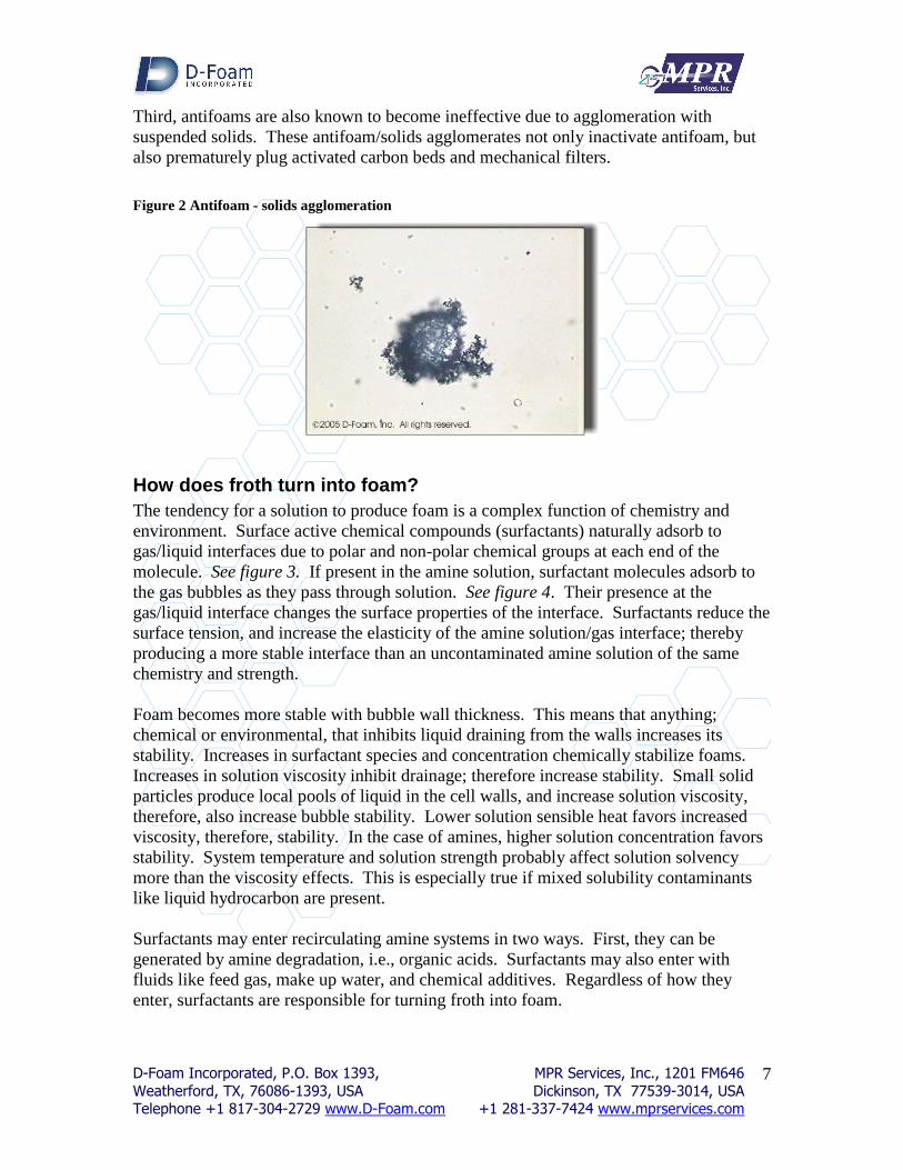
Third, antifoams are also known to become ineffective due to agglomeration with
suspended solids. These antifoam/solids agglomerates not only inactivate antifoam, but
also prematurely plug activated carbon beds and mechanical filters.
Figure 2 Antifoam - solids agglomeration
How does froth turn into foam?
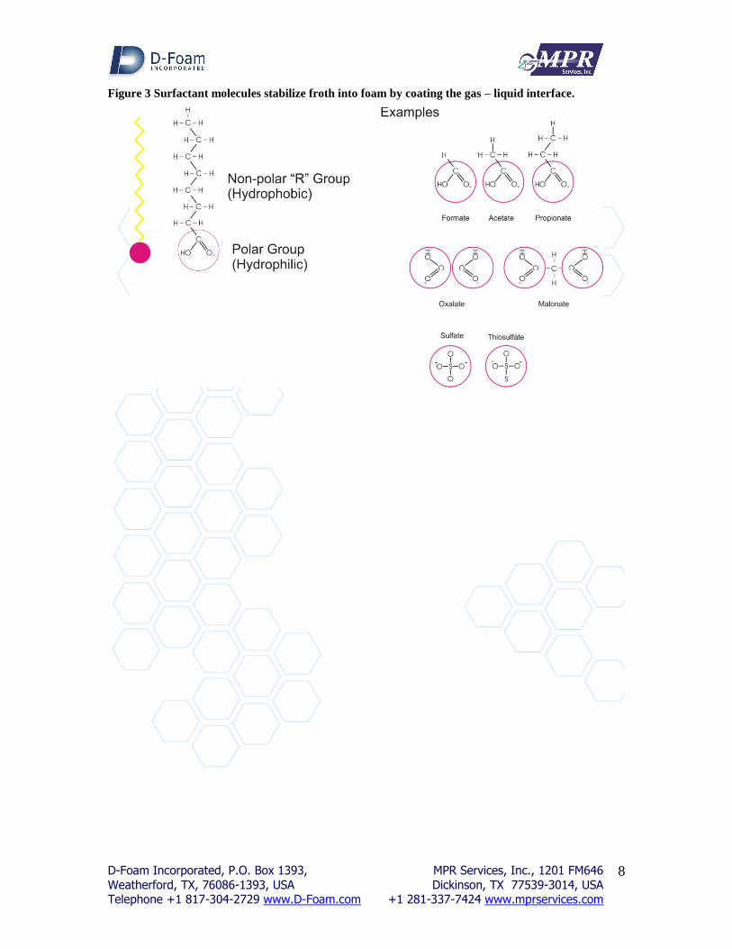
The tendency for a solution to produce foam is a complex function of chemistry and
environment. Surface active chemical compounds (surfactants) naturally adsorb to
gas/liquid interfaces due to polar and non-polar chemical groups at each end of the
molecule. See figure 3. If present in the amine solution, surfactant molecules adsorb to
the gas bubbles as they pass through solution. See figure 4. Their presence at the
gas/liquid interface changes the surface properties of the interface. Surfactants reduce the
surface tension, and increase the elasticity of the amine solution/gas interface; thereby
producing a more stable interface than an uncontaminated amine solution of the same
chemistry and strength.
Foam becomes more stable with bubble wall thickness. This means that anything;
chemical or environmental, that inhibits liquid draining from the walls increases its
stability. Increases in surfactant species and concentration chemically stabilize foams.
Increases in solution viscosity inhibit drainage; therefore increase stability. Small solid
particles produce local pools of liquid in the cell walls, and increase solution viscosity,
therefore, also increase bubble stability. Lower solution sensible heat favors increased
viscosity, therefore, stability. In the case of amines, higher solution concentration favors
stability. System temperature and solution strength probably affect solution solvency
more than the viscosity effects. This is especially true if mixed solubility contaminants
like liquid hydrocarbon are present.
Surfactants may enter recirculating amine systems in two ways. First, they can be
generated by amine degradation, i.e., organic acids. Surfactants may also enter with
fluids like feed gas, make up water, and chemical additives. Regardless of how they
enter, surfactants are responsible for turning froth into foam.
D-Foam Incorporated, P.O. Box 1393, MPR Services, Inc., 1201 FM646
Weatherford, TX, 76086-1393, USA Dickinson, TX 77539-3014, USA Telephone +1 817-304-2729 www.D-Foam.com +1 281-337-7424 www.mprservices.com
8
Figure 3 Surfactant molecules stabilize froth into foam by coating the gas – liquid interface.

D-Foam Incorporated, P.O. Box 1393, MPR Services, Inc., 1201 FM646
Weatherford, TX, 76086-1393, USA Dickinson, TX 77539-3014, USA Telephone +1 817-304-2729 www.D-Foam.com +1 281-337-7424 www.mprservices.com
9
Figure 4 Foam formation by surfactants and antifoam mechanism.
What are the most common foaming symptoms?
Diagnosing process foaming can be difficult because some hardware problems yield the
same symptoms. The two most common symptoms of amine process foaming are
column differential pressure (see figure 5), and liquid level fluctuations in column
bottoms and reboiler (See figure 6).
D-Foam Incorporated, P.O. Box 1393, MPR Services, Inc., 1201 FM646
Weatherford, TX, 76086-1393, USA Dickinson, TX 77539-3014, USA Telephone +1 817-304-2729 www.D-Foam.com +1 281-337-7424 www.mprservices.com
10
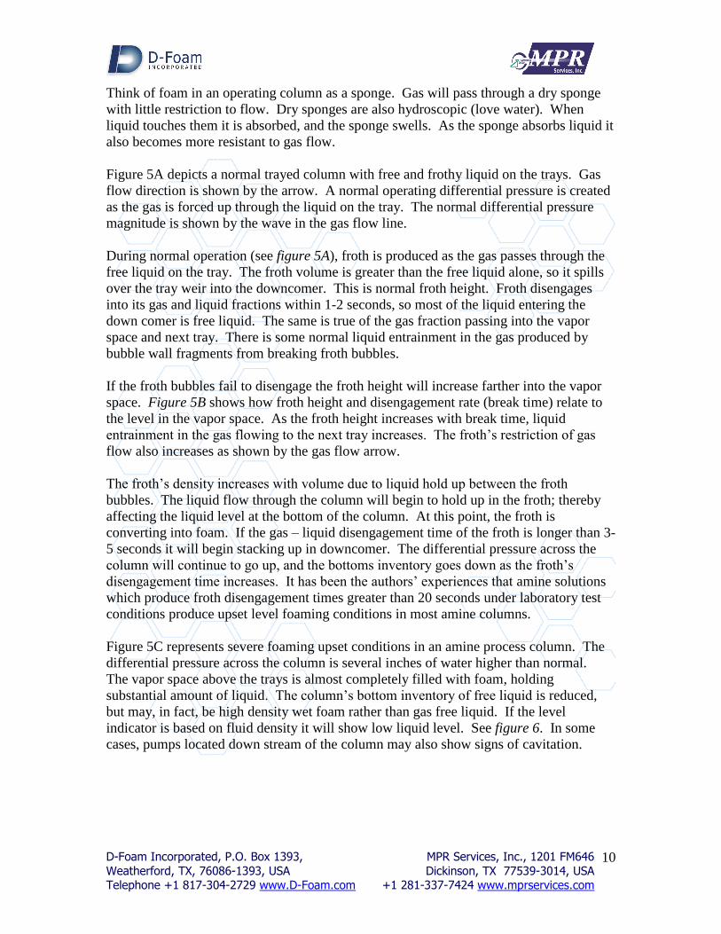
Think of foam in an operating column as a sponge. Gas will pass through a dry sponge
with little restriction to flow. Dry sponges are also hydroscopic (love water). When
liquid touches them it is absorbed, and the sponge swells. As the sponge absorbs liquid it
also becomes more resistant to gas flow.
Figure 5A depicts a normal trayed column with free and frothy liquid on the trays. Gas
flow direction is shown by the arrow. A normal operating differential pressure is created
as the gas is forced up through the liquid on the tray. The normal differential pressure
magnitude is shown by the wave in the gas flow line.
During normal operation (see figure 5A), froth is produced as the gas passes through the
free liquid on the tray. The froth volume is greater than the free liquid alone, so it spills
over the tray weir into the downcomer. This is normal froth height. Froth disengages
into its gas and liquid fractions within 1-2 seconds, so most of the liquid entering the
down comer is free liquid. The same is true of the gas fraction passing into the vapor
space and next tray. There is some normal liquid entrainment in the gas produced by
bubble wall fragments from breaking froth bubbles.
If the froth bubbles fail to disengage the froth height will increase farther into the vapor
space. Figure 5B shows how froth height and disengagement rate (break time) relate to
the level in the vapor space. As the froth height increases with break time, liquid
entrainment in the gas flowing to the next tray increases. The froth’s restriction of gas
flow also increases as shown by the gas flow arrow.
The froth’s density increases with volume due to liquid hold up between the froth
bubbles. The liquid flow through the column will begin to hold up in the froth; thereby
affecting the liquid level at the bottom of the column. At this point, the froth is
converting into foam. If the gas – liquid disengagement time of the froth is longer than 3-
5 seconds it will begin stacking up in downcomer. The differential pressure across the
column will continue to go up, and the bottoms inventory goes down as the froth’s
disengagement time increases. It has been the authors’ experiences that amine solutions
which produce froth disengagement times greater than 20 seconds under laboratory test
conditions produce upset level foaming conditions in most amine columns.
Figure 5C represents severe foaming upset conditions in an amine process column. The
differential pressure across the column is several inches of water higher than normal.
The vapor space above the trays is almost completely filled with foam, holding
substantial amount of liquid. The column’s bottom inventory of free liquid is reduced,
but may, in fact, be high density wet foam rather than gas free liquid. If the level
indicator is based on fluid density it will show low liquid level. See figure 6. In some
cases, pumps located down stream of the column may also show signs of cavitation.

D-Foam Incorporated, P.O. Box 1393, MPR Services, Inc., 1201 FM646
Weatherford, TX, 76086-1393, USA Dickinson, TX 77539-3014, USA Telephone +1 817-304-2729 www.D-Foam.com +1 281-337-7424 www.mprservices.com
11
Figure 5 Tower foaming, differential pressure and liquid level flux
Figure 6 Solution foaming and liquid level fluctuation
D-Foam Incorporated, P.O. Box 1393, MPR Services, Inc., 1201 FM646
Weatherford, TX, 76086-1393, USA Dickinson, TX 77539-3014, USA Telephone +1 817-304-2729 www.D-Foam.com +1 281-337-7424 www.mprservices.com
12
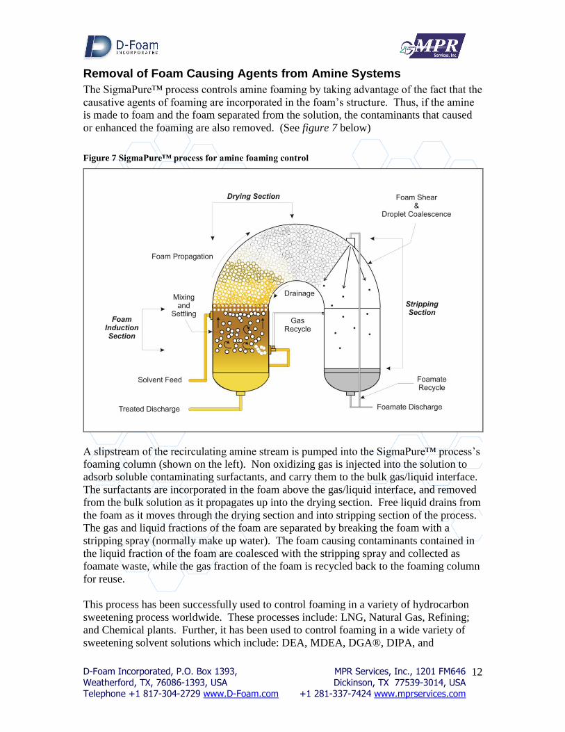
Removal of Foam Causing Agents from Amine Systems
The SigmaPure™ process controls amine foaming by taking advantage of the fact that the
causative agents of foaming are incorporated in the foam’s structure. Thus, if the amine
is made to foam and the foam separated from the solution, the contaminants that caused
or enhanced the foaming are also removed. (See figure 7 below)
Figure 7 SigmaPure™ process for amine foaming control
A slipstream of the recirculating amine stream is pumped into the SigmaPure™ process’s
foaming column (shown on the left). Non oxidizing gas is injected into the solution to
adsorb soluble contaminating surfactants, and carry them to the bulk gas/liquid interface.
The surfactants are incorporated in the foam above the gas/liquid interface, and removed
from the bulk solution as it propagates up into the drying section. Free liquid drains from
the foam as it moves through the drying section and into stripping section of the process.
The gas and liquid fractions of the foam are separated by breaking the foam with a
stripping spray (normally make up water). The foam causing contaminants contained in
the liquid fraction of the foam are coalesced with the stripping spray and collected as
foamate waste, while the gas fraction of the foam is recycled back to the foaming column
for reuse.
This process has been successfully used to control foaming in a variety of hydrocarbon
sweetening process worldwide. These processes include: LNG, Natural Gas, Refining;
and Chemical plants. Further, it has been used to control foaming in a wide variety of
sweetening solvent solutions which include: DEA, MDEA, DGA®, DIPA, and
D-Foam Incorporated, P.O. Box 1393, MPR Services, Inc., 1201 FM646
Weatherford, TX, 76086-1393, USA Dickinson, TX 77539-3014, USA Telephone +1 817-304-2729 www.D-Foam.com +1 281-337-7424 www.mprservices.com
13
FLEXSORB®. The SigmaPure™ process is not plant, process, or solution specific.
Further, use of the SigmaPure™ process has not been found to negatively affect the
sweetening solutions in any way. If the solution can be made to foam, it can be
controlled with this portable process.
Conclusion
Amine solutions foam because normal froth is stabilized into foam by contaminating
surfactants. The most common way to control foaming has been injecting antifoaming
chemicals into the recirculating solution stream to break the foam. The efficiency of
antifoams can be reduced in a variety of ways; therefore, are unreliable as a long term
control solution. The only way to actually control amine foaming over the long term is to
remove the foam causing surfactants. The SigmaPure process is a proven way to remove
foam causing surfactants from operating amine systems.
Bibliography
1. von Phul, S.A., “Sweetening Process Foaming and Abatement”, Laurance Reid Gas
Conditioning Conference, Norman, OK, 2001.
2. von Phul, S.A., “Sweetening Process Foaming and Abatement Part II: Case Studies”,
Laurance Reid Gas Conditioning Conference, Norman, OK, 2002.
3. von Phul, S.A., Stern, L., “Antifoam - What is it?”, Laurance Reid Gas Conditioning
Conference, Norman, OK, 2005.
4. von Phul, S.A., “Solution Foaming in Gas/Liquid Treating Towers”, AIChE Petrochem
Expo - Distillation Troubleshooting, Atlanta, GA, 2005.
Trademarks:
DGA® is a registered trademark of Huntsman Corporation
Flexsorb® is a registered trademark of ExxonMobil
SigmaPure™ is a trademark of D-Foam, Incorporated