Control of Difference of Seismic Response Across Different ...
23
Control of Difference of Seismic Response Across Different Spans of High-Speed Railway Multi-Spans Simply Supported Bridge Yuntai Zhang Central South University Lizhong Jiang Central South University Wangbao Zhou ( [email protected] ) Central South University https://orcid.org/0000-0003-3338-4971 Zhipeng Lai Central South University Xiang Liu Fujian University of Technology Kang Peng Central South University Zheng Wang Central South University Yulin Feng East China JiaoTong University Research Article Keywords: Difference of Seismic Response across Different Spans, high speed railway bridge, seismic analysis, Bridge-track system, track constraint, CRTS II ballastless track structure Posted Date: August 26th, 2021 DOI: https://doi.org/10.21203/rs.3.rs-814072/v1 License: This work is licensed under a Creative Commons Attribution 4.0 International License. Read Full License
Transcript of Control of Difference of Seismic Response Across Different ...

Control of Difference of Seismic Response AcrossDifferent Spans of High-Speed Railway Multi-SpansSimply Supported BridgeYuntai Zhang
Central South UniversityLizhong Jiang
Central South UniversityWangbao Zhou ( [email protected] )
Central South University https://orcid.org/0000-0003-3338-4971Zhipeng Lai
Central South UniversityXiang Liu
Fujian University of TechnologyKang Peng
Central South UniversityZheng Wang
Central South UniversityYulin Feng
East China JiaoTong University
Research Article
Keywords: Difference of Seismic Response across Different Spans, high speed railway bridge, seismicanalysis, Bridge-track system, track constraint, CRTS II ballastless track structure
Posted Date: August 26th, 2021
DOI: https://doi.org/10.21203/rs.3.rs-814072/v1
License: This work is licensed under a Creative Commons Attribution 4.0 International License. Read Full License

Control of Difference of Seismic Response across Different Spans
of High-Speed Railway Multi-spans Simply Supported Bridge Yuntai Zhang1, Lizhong Jiang 1, 2, Wangbao Zhou 1*, Zhipeng Lai 1, Xiang Liu 3
Kang Peng 1, Zheng Wang 1 & Yulin Feng 4
1 School of Civil Engineering, Central South University, Changsha 410075, China; 2 National Engineering Laboratory for High Speed Railway Construction, Changsha 410075, China;
3 School of Civil Engineering, Fujian University of Technologh, Fuzhou 350118, China; 4 School of Civil Engineering and Architecture, East China Jiaotong University, Nanchang 330013, China;
Abstract: In this paper, the Difference of Seismic Response across Different Spans (DSR) in the longitudinal distribution of High-Speed Railway Multi-spans Simply Supported Bridge (HSRSB) under longitudinal earthquake excitation is investigated, and an evaluation method which can intuitively reflect the difference of seismic response is proposed. A feasible way to strengthen the connection stiffness between adjacent girders is proposed to control DSR. The rationality of the finite element model used is verified by comparing the numerical results with the experimental ones, showing a satisfactory agreement. Comparing the seismic response of a bridge model considering the subgrade-track constraints (BCTM) and a bridge model without subgrade-track constraints (BWTM), it is found that the DSR in the longitudinal distribution causes some new disadvantages, which are neglected in BWTM. The BCTM considering DLC generates a model called BCDM. The effect of the number of span on DSR are studied based on BCDM. The analysis of this model showed that DLC suppresses the DSR and reduces the seismic response of most bridge components. It also transfers the seismic disadvantage from the bridge part to the subgrade-track structure. As it is more convenient and cost-effective to repair the base plate of the subgrade than the bridge components after earthquake seismic event, this disadvantage transfer is in favor of forming a new anti-seismic system that subgrade-track structure is used to protect the bridge part. Keywords: Difference of Seismic Response across Different Spans; high speed railway bridge; seismic analysis; Bridge-track system; track constraint; CRTS II ballastless track structure
The Highlights of the paper:
We summarize the disadvantages caused by the Difference of Seismic Response across Different Spans (DSR) in the longitudinal direction of High-Speed Railway Multi-spans Simply Supported Bridge (HSRSB), which are easily overlooked in previous seismic study in HSRSB.
We propose an evaluation method to evaluate the controlling effect on DSR.
We propose an improved unseating prevention device, called Difference Level Controller (DLC) to control these disadvantages caused by DSR.
The biggest highlight of this study is the discovery that adopting DLC, the seismic disadvantage is transferred from the bridge part to the subgrade-track structure, which is more cost-effective and convenient to repair after an earthquake. Therefore, this disadvantage transfer is in favor of forming a new innovative cost-effective anti-seismic
Corresponding author, Ph.D., E-mail: [email protected]; ORCID: 0000-0003-3338- 4971

system that subgrade-track structure is used to protect the bridge part.
1. Introduction
With the increasing requirement of line smoothness and passenger comfort for high-speed railway lines, simply supported girder bridges with multi-spans for several kilometers are commonly used[1,2]. Moreover, due to the necessity of the construction of high-speed railway lines in areas with high seismicity, many researchers focus their interest on the anti-seismic design of the high-speed railway multi-spans simply supported bridges (HSRSB). In previous studies of the anti-seismic design of the HSRSB, the simply supported bridge was modeled without considering track constraints, but simplifying the track structure with additional masses on the girder. This consideration can reduce the modeling complexity and improve the calculation efficiency. Benefited from the convenience of the simply supported bridge models without considering track constraint models, a large number of anti-seismic designs for bearings and piers have been studied based on this concept [3-6]. Based on a simply supported reinforced concrete (RC) beam test, the capacity of the shear pins had a great influence on the bending moment of pier was presented by Xia [7], which should be considered in seismic design. In Jiang's study [8], a scaled experimental 2-span model without considering subgrade was tested on shake table for each bridge to validate the rationality of all models and the appropriate strength of FPB shear pin was achieved. However, it should be mentioned that this assumption may lead to unreasonable responses in seismic analysis, due to the coupling effect between adjacent spans caused by the track constraints, which is neglected [9,10].
Considerable researches have been conducted to investigate the track constraint effects on the bridge. These studies mainly focus on bridge-track interaction [11,12] or train-track interaction [13-15]. Maragakis [16] investigated the effect of tracks on the dynamic performance of Strawberry Park ballasted bridge. According to the experimental results, significant vibration is transmitted to the adjacent subgrade when a track exists in the edge of the bridge; the fundamental frequencies of structures in longitudinal, transverse, and vertical directions all decline to some extents when tracks are cut off. Based on the experimental research and theoretical analysis, Iemura [17] believed that the rail constraint has a certain impact on the energy dissipation capacity of the anti-seismic device. Toyooka [18] found that the effect of the track constraint on the longitudinal natural frequency of
railway bridges with vibration absorption and isolation devices was not negligible. In view of
ballasted-CRTS II ballastless track transition section on the bridge of Beijing-Shanghai high-speed
railway, Liu [1] proposed the recommended value of reasonable length of transition section. In numerical and experimental analyses of a steel truss railway bridge from Bornet [19], it is found that the stiffness of the ballast (modelled by its Young’s modulus) and the continuity of the ballast and the track before and after the bridge do not have any significant effects for the first vertical bending and the first torsional modes, but have a significant effect on the second vertical bending mode. The displacement reducing of the ballastless track for high-speed railway bridge due to track constraints was investigated by shaking table tests for earthquake simulation [20]. Jiang and Zhang [21,22]found that the subgrade part of high-speed railway simply supported beam bridge-track structure system has a critical rail length by evaluating the natural vibration characteristics under different interlayer stiffness and lengths of rails at different subgrade parts.
Although many studies have found that track constraints can reduce the displacement of some simply supported bridge components with multi-spans [22], it is worth noting that the Difference of Seismic Response across Different Spans (DSR) of HSRSB caused by track constraints may lead to

new disadvantages. Li [23] found that the stress of the rail is higher in the span near the subgrade and the peak of the stress is higher near the expansion joints with incorporation of seismic isolators. Yan[24] found that the peak stresses of rail, track plate and base plate all occur at the abutment or anchors and both track plate and base plate are about to crack. It can be argued that the current design of anti-seismic based on simple models, which neglect the subgrade-track constraints, may overlook the disadvantages caused by DSR. Further, the underestimation of track constraints makes the effect of some isolation devices not substantially different between Railway Bridges and Highway Bridges and thus rarely investigated in HSRSB, such as unseating prevention devices. The unseating prevention device, which is used to prevent adjacent girder pounding and girder falling, has been extensively studied in seismic analysis of highway Bridges [25-27]. However, in the HSRSB, the bridge-track-subgrade interaction may change the isolation effect of unseating prevention devices, which cannot be detected in the study of Highway Bridge. Therefore, when the seismic analysis includes the whole multi-span railway bridge and subgrade-track as one system, it is worth studying the influence of the unseating prevention device on HSRSB seismic responses.
The aim of this paper is to summarize the disadvantages caused by the Difference of Seismic Response across Different Spans (DSR) in the longitudinal direction of HSRSB, and propose an evaluation index called Difference Level to reflect the DSL. A hypothetical device, called Difference Level Controller (DLC), which can strengthen the connection stiffness between adjacent girders is proposed to control these disadvantages. The bridge model considering subgrade-track constraints (BCTM), the bridge model without subgrade-track constraints (BWTM) and the bridge model with subgrade-track constraints considering also DLC with different stiffnesses (BCDM) are established for the analysis and their seismic response is numerically calculated. A comparison between these models leads to interesting conclusions regarding the effect on a HSRSB. The rationality of the finite element model is verified by comparing the numerical results with experimental data. Comparing the seismic response of BCTM and BWTM, the typical disadvantages that are caused by the DSR in longitudinal direction are identified. Based on the seismic analysis of BCDM, the control effects of DLC and span number on DSR are investigated. A new anti-seismic conception that subgrade-track structure is used to protect the bridge part is proposed which can greatly reduce the seismic damage risk of bridge structure.
2. Evaluation method for DSR
Assuming that a number of sampling points of a component are selected along the longitudinal direction on an n-spans HSRSB. The DSR of the bridge can be evaluated through the Overall Difference Level (ϕ) of the seismic response:
1
1 1C
c
c
(1)
where C is the number of components considered for analysis, and φ is the Difference Level of seismic response of cth component. When ϕ approaches 1, it indicates that at least one component has a high Difference Level. The closer ϕ is to 0, the lower the difference level of all the components considered in the bridge are, and the more credible the bridge's DSR is controlled.
φ can be expressed in Eq. (2) as follows:
1
1 1n
i i
i
(2)
where γj is the deviation weight coefficient of seismic response on ith span, and δj is the local

difference sensitivity of seismic response on ith span. The closer φ is to 0, the more identical the seismic responses of all spans are, and the more effectively the component's DSR is controlled.
γj can be expressed in Eq. (3)as follows:
2
2
1
i U
i n
i Ui
U S
U S
(3)
δj can be expressed in Eq. (7) as follows:
2 2
1 111 exp exp
2
i i i i
i
U U
U U U U
S S
(4)
where Ui is the characteristic seismic response of the component on ith span, and SU is the median value of the characteristic seismic responses. Ui can be expressed in Eq. (5) as follows:
1
J
i ij ij
j
U R
(5)
1
Jij
ij
j ij
R
R
(6)
1
1 J
ijjR
J
(7)
J is the total sampling number on each span, and R is the peak seismic response of the sampling point.
When a series of seismic records are considered, the differential level of the component can be expressed as:
1
1 H
h
h
ΓH
(8)
And the overall differential level of the bridge can be expressed as:
1
1 H
h
h
ΦH
(9)
where H is the number of seismic records considered for analysis.
3. Numerical model In order to analyze the DSR, the bridge model considering subgrade-track constraints (BCTM)
and bridge model without subgrade-track constraints (BWTM) are established in Section 3.2. In order to analyze the control effect of the DLC, a series of BCTMs with DLC of different stiffness (BCDM) are established.
3.1 Description of the bridge
The typical High-Speed Railway Multi-spans Simply Supported Bridge (HSRSB) is shown in Fig. 1. The HSRSB models in this paper can be established and analyzed by the finite element software ANSYS. According to the finite element type used, the components of the HSRSB model

are divided into main and connecting components.
The main components include girders, piers, base slabs, track slabs and rails. They are simulated by beam-4 element without considering any failure modes. The length of elements is 0.645 m. The girder is a typical 32 m double-line standard simply supported beam and its concrete strength grade is C30. The piers with height of 20 m have a circular with round-end section. The concrete strength grade of the piers is C40. The base slab, the track slab and the rail form the standard CRTSII ballastless track material. The girder cross-section and the pier cross-section are shown in Fig. 2.
The connecting components are used to connect the main components, including fasteners, CA mortar, sliding layer, shear teeth, shear bar and bearings. They are simulated by combine-39 elements. The mass of the connecting components is not considered in the model of the bridge, as it is negligible. The longitudinal force-displacement curves of the connecting components are shown in Fig. 3. Assuming that the length of the track elements is 0.645 m, the stiffnesses of all connecting components, which are referenced from the previous literature [22,28], are listed in Table. 1-Table. 2. ky and kz are transverse and vertical stiffness of interlayer components, respectively.
Fig. 1 Typical high-speed railway simply supported bridge with CRTSII ballastless track.
6.7
0.7
1.3 2.1 0.6 2.8
2.0
2.5
1.8
0.5
0.6
3.0
2.51.5
(a) (b)
Girder
Bearing
Pier
Rail
Fastener
Track plate
CA layer
Base plate
Sliding layer

Fig. 2 Cross-section of: (a) girder; (b) pier (unit: m).
(a) (b)
Fig. 3 The force-displacement curves in (a) longitudinal direction (b) transerve or vertical direction
Table. 1 Longitudinal stiffness of interlayer components (unit: kN, m)
Interlayer component Fastener CA layer Sliding
layer Fixed
bearing
Sliding bearing
Lateral block
Sheer teeth
Sheer bars
F0 8.66 4.50E+01 6.00 1.00E+03 - - 1.20E+05 1.80E+02
D0 2.00E-03 5.00E-04 5.00E-04 2.00E-03 - - 1.20E-04 7.50E-05
k0 4.33E+03 9.00E+04 1.20E+04 5.00E+05 5.00E+03 0 1.00E+09 2.4E+06
k1 0 0 0 5.00E+03 5.00E+03 0 0 0
Table. 2 Transverse and vertical stiffness of interlayer components (unit: kN, m)
Interlayer component Fastener CA layer Sliding
layer Fixed
bearing
Sliding bearing
Lateral block
Sheer teeth
Sheer bars
ky 1.623E+03 9.00E+04 1.20E+04 5.00E+05 5.00E+05 1.20E+04 1.00E+09 2.4E+06
kz 1.385E+04 2.00E+08 1.37E+08 1.00E+07 1.00E+07 0 1.40E+08 2.00E+08
3.2 Consideration of subgrade-track constraint
The subgrade-track constraint causes the seismic response to differ across the spans of HSRSB along the longitudinal direction, denoted as the Difference of Seismic Response across Different Spans (DSR). The HSRSB model recommended by the current Chinese seismic design code[29] without considering this longitudinal constraint of subgrade-track may ignores the disadvantages caused by DSR. In order to explore the influence of DSR on the seismic response of railway bridges, two finite element models of 11-spans HSRSB with different boundary conditions are established (Fig. 4). The two models are denoted as the bridge model considering subgrade-track constraints (BCTM) and the bridge model without subgrade-track constraints (BWTM). The length of subgrade is assumed to be 100 m, including 50 m friction plate section. The stiffness of the friction plate is consistent with the one of the sliding layer given in Table. 1.

(a)
(b)
Fig. 4 Finite element model of (a) BCTM; (a) BWTM
3.3 Control of Difference of Seismic Response across Different Spans
Under seismic excitation, the track structure provides constraint to coordinate the displacement difference between the subgrade and the bridge structure. However, due to the limited strength of track constraint, the seismic response of spans near the subgrade may be quite different from that of spans far away from the subgrade. Therefore, it is a worthwhile scheme to strengthen the connection stiffness between adjacent girders to control DSR.
In this paper, an unseating prevention device, denoted as Difference Level Controller (DLC), is proposed to strengthen the connection stiffness between adjacent girders. DLC is set between adjacent girders to constrain their relative displacement. The construction of DLC can refer to the Connecting Rod Unseating Prevention Device (Fig. 5) [27]. In this paper, it is assumed that there is no initial gap in the DLC, that the temperature deformation is not considered, and that DLC will not be damaged after a seismic event. Therefore, in the finite element model it is represented by a linear elastic spring in the longitudinal direction (Fig. 6). Several BCTMs with DLC of different stiffnesses (BCDM) are established to determine the control effect of the DLC. The stiffness of the DLC are described in Section 5.2.
Fastener Rail Sheer bars track plate CA layer
Track plate Sheer teeth Sliding layer
Pier Fixed Bearing Girder P0 P1 P2 P3

CA layer
base slab
track slab
sliding layer
girder
Unseating Prevention
Devices
Fig. 5 Connecting Rod Unseating Prevention Device [27]
Fig. 6 Finite element model of BCDM
4. Validation of finite element model In order to validate the rationality of the finite element model used to analyze the effect of DSR,
a shake table test was carried out [30,31]. In the experiment, a shaking table system was used to apply the seismic excitation at a scale HSRSB model of 11-spans without considering the subgrade-track constraint (Fig. 7). The shaking table system consisted of four 4 m × 4 m shaking tables, each of which could bear a maximum mass of 30 tons and provide a maximum horizontal acceleration of 1.0 g. The high-speed camera system was used to capture the displacement of the structural components at the speckle areas. The observation area was arranged between girders 5 and 6 (Fig. 8). The seismic results on the measuring points within the girder end area that derive from the numerical analyses are compared to the experimental ones and this comparison is shown in Fig. 9. It can be seen that the calculation results of the finite element model established in this paper show a good agreement with the ones of the test. It indicates that the finite element model established in this paper can accurately simulate the structural vibration under the seismic excitation and can be used to analyze.
DCD
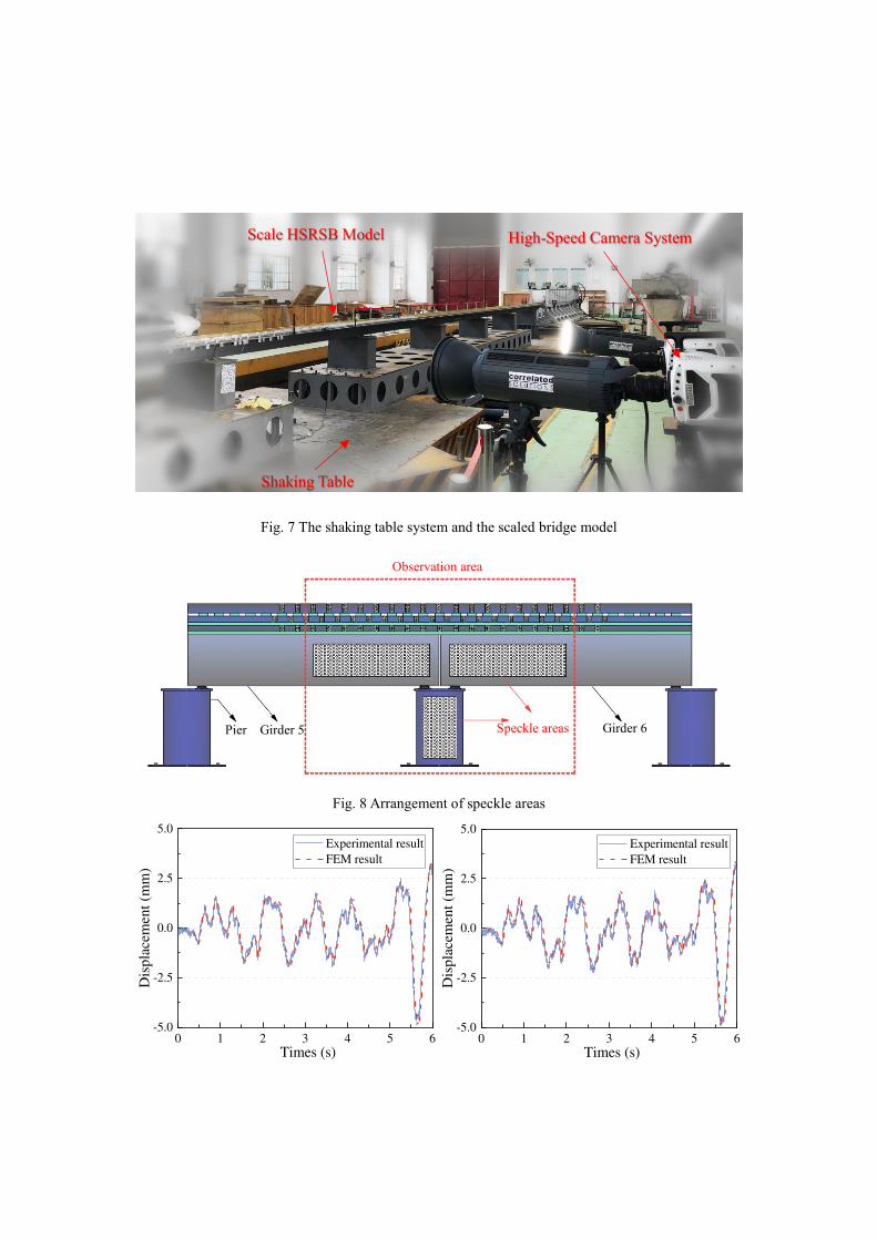
Fig. 7 The shaking table system and the scaled bridge model
Fig. 8 Arrangement of speckle areas
0 1 2 3 4 5 6-5.0
-2.5
0.0
2.5
5.0
Experimental result
FEM result
Dis
pla
cem
ent
(mm
)
Times (s)
0 1 2 3 4 5 6-5.0
-2.5
0.0
2.5
5.0
Experimental result
FEM result
Dis
pla
cem
ent
(mm
)
Times (s)
Pier Girder 5 Speckle areas Girder 6
Observation area
Shaking Table
Scale HSRSB Model High-Speed Camera System

(a) (b)
Fig. 9 Comparison of seismic responses
(a) Displacement of right end of 5# girder (b) Displacement of left end of 6# girder
5. Analysis of Difference of Seismic Response across Different Spans
5.1 Influence of subgrade-track constraints on seismic responses
The influence of subgrade-track constraint on the longitudinal distribution of seismic response is investigated based on BWTM and BCTM. In order to better reflect the utilization difference among fixed bearings after the earthquake, the formula for calculating the internal force utilization (αi) of bearings is proposed: 0i i
Q F (10)
where Qi is the maximum force of the fixed bearing on ith span, F0,x is the force corresponding to the initial stiffness of the fixed bearing in Table. 1. When G is closer to 1, it indicates that the utilization of the bearing is higher, whereas the utilization of the bearing is lower.
In general, the first eigenmode of a HSRSB is longitudinal vibration, which is related to the study of longitudinal seismic responses. The displacements of first natural mode of the girder middle point of BWTM and BCTM are shown in Fig. 11. The displacements of all the spans in BWTM have small differences, while the side spans have smaller displacements than other spans in BCTM. This indicates that the basic dynamic characteristics of the two models are different.
To preliminarily study Difference of Seismic Response across Different Spans in longitudinal direction, an earthquake record with a peak acceleration of 0.2 g and a characteristic period (Tg) of 0.35 s was selected for seismic analysis in longitudinal direction. The acceleration time history and the acceleration spectrum are shown in Fig. 10. The seismic response results corresponding to the peak ground acceleration of 0.1 g are also calculated. Rayleigh damping was applied to all structural components with a damping ratio of 3% associated to 1st mode and 2nd mode. Dynamic analysis was carried out to obtain the seismic responses.
Fig. 12 presents the envelope diagrams of the longitudinal seismic responses of BWTM and BCTM under different peak ground accelerations. Similar to the modal analysis, the seismic response of BWTM slightly varies between its spans. The seismic response of the middle span of BCTM is close to the corresponding one of BWTM, but approaching the side spans, the difference between the two models increases. Compared with BWTM, the girder displacement of the side spans of BCTM is significantly reduced (Fig. 12 (b)), but the relative displacement of the adjacent girders is larger (Fig. 12 (a)). The relative displacement increases as peak ground acceleration increases, indicating that the disadvantage of girder pounding of BCTM is larger with respect to the BWTM. The internal force utilization (αi) of the side span bearings in BCTM is smaller than other spans (Fig. 12 (c)). For a peak ground acceleration of 0.2 g, the internal force utilization of bearings in BWTM reaches 1.0 for all bearings. However, the one of the side span bearings in BCTM are smaller than 1.0, which means that the utilization of some bearings do not meet the design requirements if the subgrade-track constraints are considered. It can be seen in Fig. 12 (d) that the rail axial forces in BWTM are very small, and the maximum force is only 0.6% of the corresponding one of BCTM, which is also the reason why the subgrade-track structure constraint has been neglected in many previous studies based on BWTM. The larger axial force in BCTM is caused by the track-structure, which acts as longitudinal connection component and controls the displacement difference of the adjacent girders. The Difference Levels of seismic response of BCTM and BWTM are compared

(Fig. 13), including girder displacement (φGD), relative displacement (φRD), internal force utilization (φBF), rail axial forces (φRF) and the bridge (ϕBR). The Difference Levels of components of BCTM are all larger than those of BWTM, so the overall difference level of the bridge is also higher. And the difference levels under with different peak accelerations are almost the same. It can be seen that the Difference Levels can intuitively reflect the disadvantage of the component caused by DSR.
In conclusion, the disadvantages caused by DSR can be divided into: (1). larger risk of adjacent girders pounding, (2) low utilization of some bearings and (3) larger axial forces of the rail on the bridge. As the peak ground acceleration increases, these disadvantages are amplified. Therefore, it is very important to control the Difference of Seismic Response across Different Spans (DSR) of HSRSB from the perspective of engineering economy and safety.
(a) (b)
Fig. 10 The earthquake record: (a) time history curve; (b) acceleration spectrum
Fig. 11 The displacements of first eigenmode of girders
0 5 10 15 20 25-0.15
-0.10
-0.05
0.00
0.05
0.10
0.15
0.20
0.25
Accele
rati
on
(g)
Time (s)
0.4 0.8 1.2 1.6 2.0 2.4 2.80.0
0.1
0.2
0.3
0.4
0.5
0.6
Accele
rati
on m
agnif
icati
on (
g)
Period (s)
1 3 5 7 9 110.0
0.2
0.4
0.6
0.8
1.0
1.2
BWTM
BCTM
Mo
dal
dis
pla
cem
en
t
Girder number

(a) (b)
(c) (d)
Fig. 12 The envelope diagrams of the longitudinal seismic responses of
(a) girders relative displacement; (b) girder displacement; (c) bearing force utilization; (d) rail force
1 3 5 7 90
1
2
3
4
5
BWTM 0.1g BWTM 0.2g
BCTM 0.1g BCTM 0.2g
rela
tive d
ispla
cem
ent
(mm
)
ICD number
1 3 5 7 9 110
4
8
12
16
dis
pla
cem
ent
(mm
)Girder number
1 3 5 7 90
200
400
600
800
1000
1200
i
Fixed bearing number
0 50 100 150 200 250 300 350-50
0
50
100
150
200
250
BWTM 0.1g BWTM 0.2g
BCTM 0.1g BCTM 0.2g
Fo
rce (
kN
)
Longitudinal length (m)
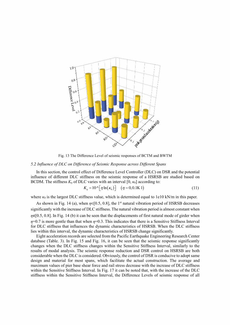
Fig. 13 The Difference Level of seismic responses of BCTM and BWTM
5.2 Influence of DLC on Difference of Seismic Response across Different Spans
In this section, the control effect of Difference Level Controller (DLC) on DSR and the potential influence of different DLC stiffness on the seismic response of a HSRSB are studied based on BCDM. The stiffness Kη of DLC varies with an interval [0, κ0] according to: 010 ^ ln 0,0.1 1K K (11)
where κ0 is the largest DLC stiffness value, which is determined equal to 1e10 kN/m in this paper. As shown in Fig. 14 (a), when η∈[0.5, 0.8], the 1st natural vibration period of HSRSB decreases
significantly with the increase of DLC stiffness. The natural vibration period is almost constant when η∉[0.5, 0.8]. In Fig. 14 (b) it can be seen that the displacements of first natural mode of girder when η=0.7 is more gentle than that when η=0.3. This indicates that there is a Sensitive Stiffness Interval for DLC stiffness that influences the dynamic characteristics of HSRSB. When the DLC stiffness lies within this interval, the dynamic characteristics of HSRSB change significantly.
Eight acceleration records are selected from the Pacific Earthquake Engineering Research Center database (Table. 3). In Fig. 15 and Fig. 16, it can be seen that the seismic response significantly changes when the DLC stiffness changes within the Sensitive Stiffness Interval, similarly to the results of modal analysis. The seismic response reduction and DSR control on HSRSB are both considerable when the DLC is considered. Obviously, the control of DSR is conducive to adopt same design and material for most spans, which facilitate the actual construction. The average and maximum values of pier base shear force and rail stress decrease with the increase of DLC stiffness within the Sensitive Stiffness Interval. In Fig. 17 it can be noted that, with the increase of the DLC stiffness within the Sensitive Stiffness Interval, the Difference Levels of seismic response of all
B R
RF
BF
RD
GD
0.1
0 .2
0 .30.0
0.2
0.4
0.6
0.8
1.0
peak gr
ound ac
celera
tion (
g)D
ifference L
evel
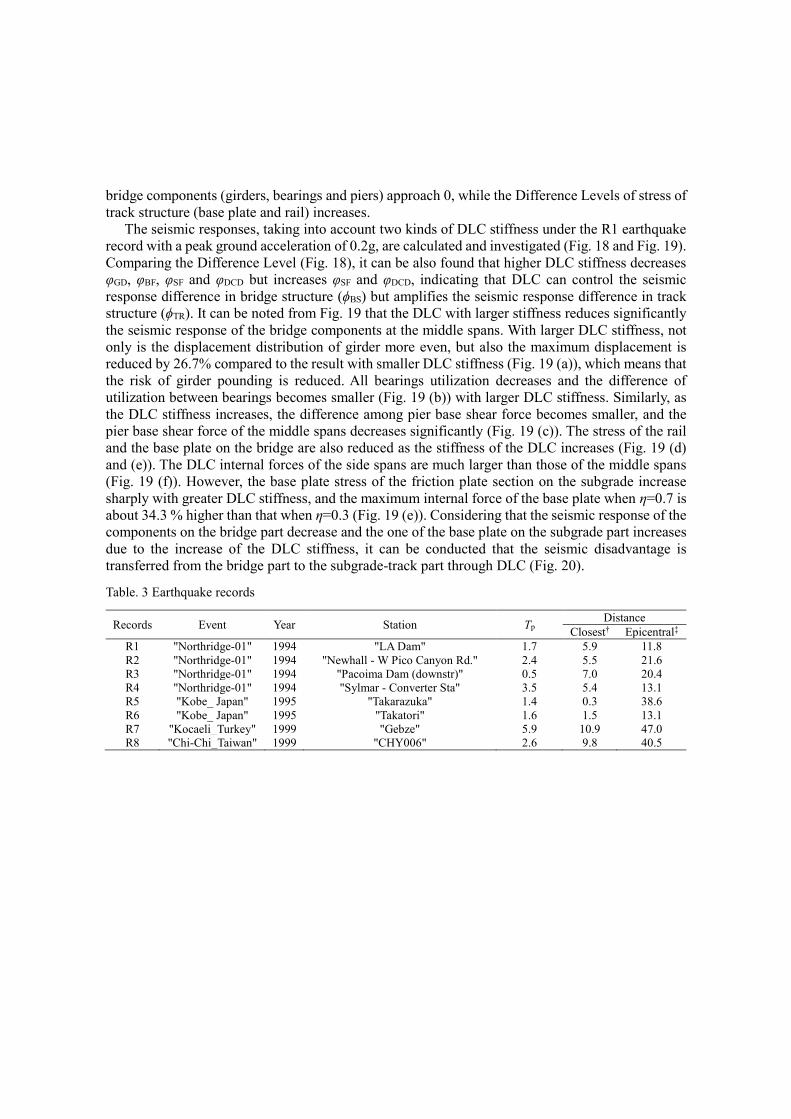
bridge components (girders, bearings and piers) approach 0, while the Difference Levels of stress of track structure (base plate and rail) increases.
The seismic responses, taking into account two kinds of DLC stiffness under the R1 earthquake record with a peak ground acceleration of 0.2g, are calculated and investigated (Fig. 18 and Fig. 19). Comparing the Difference Level (Fig. 18), it can be also found that higher DLC stiffness decreases φGD, φBF, φSF and φDCD but increases φSF and φDCD, indicating that DLC can control the seismic response difference in bridge structure (ϕBS) but amplifies the seismic response difference in track structure (ϕTR). It can be noted from Fig. 19 that the DLC with larger stiffness reduces significantly the seismic response of the bridge components at the middle spans. With larger DLC stiffness, not only is the displacement distribution of girder more even, but also the maximum displacement is reduced by 26.7% compared to the result with smaller DLC stiffness (Fig. 19 (a)), which means that the risk of girder pounding is reduced. All bearings utilization decreases and the difference of utilization between bearings becomes smaller (Fig. 19 (b)) with larger DLC stiffness. Similarly, as the DLC stiffness increases, the difference among pier base shear force becomes smaller, and the pier base shear force of the middle spans decreases significantly (Fig. 19 (c)). The stress of the rail and the base plate on the bridge are also reduced as the stiffness of the DLC increases (Fig. 19 (d) and (e)). The DLC internal forces of the side spans are much larger than those of the middle spans (Fig. 19 (f)). However, the base plate stress of the friction plate section on the subgrade increase sharply with greater DLC stiffness, and the maximum internal force of the base plate when η=0.7 is about 34.3 % higher than that when η=0.3 (Fig. 19 (e)). Considering that the seismic response of the components on the bridge part decrease and the one of the base plate on the subgrade part increases due to the increase of the DLC stiffness, it can be conducted that the seismic disadvantage is transferred from the bridge part to the subgrade-track part through DLC (Fig. 20).
Table. 3 Earthquake records
Records Event Year Station Tp Distance
Closest† Epicentral‡
R1 "Northridge-01" 1994 "LA Dam" 1.7 5.9 11.8
R2 "Northridge-01" 1994 "Newhall - W Pico Canyon Rd." 2.4 5.5 21.6
R3 "Northridge-01" 1994 "Pacoima Dam (downstr)" 0.5 7.0 20.4
R4 "Northridge-01" 1994 "Sylmar - Converter Sta" 3.5 5.4 13.1
R5 "Kobe_ Japan" 1995 "Takarazuka" 1.4 0.3 38.6
R6 "Kobe_ Japan" 1995 "Takatori" 1.6 1.5 13.1
R7 "Kocaeli_Turkey" 1999 "Gebze" 5.9 10.9 47.0
R8 "Chi-Chi_Taiwan" 1999 "CHY006" 2.6 9.8 40.5

(a) (b)
Fig. 14 Modal analysis of BCDM
(a) Effect of DLC stiffness on period (b) Modal displacement of girder with different DLC stiffness
(a) (b)
Fig. 15 The shear force of pier base with respect to η (a) 0.1 g; (b) 0.2 g
(a) (b)
0.0 0.2 0.4 0.6 0.8 1.00.26
0.28
0.30
0.32
0.34
0.36
0.38
0.40
Peri
od
(s)
1 2 3 4 5 6 7 8 9 10
0.2
0.4
0.6
0.8
1.0
Mo
dal
dis
pla
cem
en
t o
f P
ier
top
Pier number
=0.3 =0.7
0.0 0.2 0.4 0.6 0.8 1.01000
1500
2000
2500
3000
3500
4000
4500
Fo
rce (
kN
)
average
maximum
minimum
0.0 0.2 0.4 0.6 0.8 1.01000
1500
2000
2500
3000
3500
4000
4500
Fo
rce (
kN
)
0.0 0.2 0.4 0.6 0.8 1.00
4
8
12
16
20
Str
ess
(M
Pa)
average
maximum
minimum
0.0 0.2 0.4 0.6 0.8 1.00
4
8
12
16
20
Str
ess
(M
Pa)
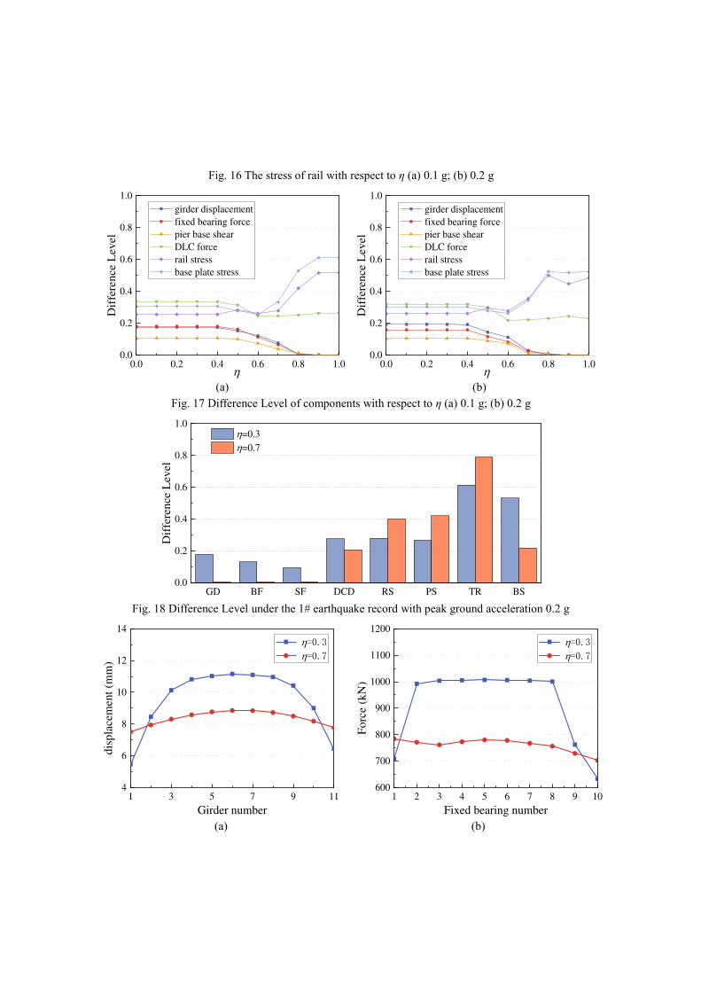
Fig. 16 The stress of rail with respect to η (a) 0.1 g; (b) 0.2 g
(a) (b)
Fig. 17 Difference Level of components with respect to η (a) 0.1 g; (b) 0.2 g
Fig. 18 Difference Level under the 1# earthquake record with peak ground acceleration 0.2 g
(a)
(b)
0.0 0.2 0.4 0.6 0.8 1.00.0
0.2
0.4
0.6
0.8
1.0
girder displacement
fixed bearing force
pier base shear
DLC force
rail stress
base plate stress
Dif
fere
nce L
evel
0.0 0.2 0.4 0.6 0.8 1.00.0
0.2
0.4
0.6
0.8
1.0
D
iffe
rence L
evel
girder displacement
fixed bearing force
pier base shear
DLC force
rail stress
base plate stress
GD BF SF DCD RS PS TR BS0.0
0.2
0.4
0.6
0.8
1.0
Dif
fere
nce L
evel
=0.3
=0.7
1 3 5 7 9 114
6
8
10
12
14
=0.3 =0.7
dis
pla
cem
en
t (m
m)
Girder number
1 2 3 4 5 6 7 8 9 10600
700
800
900
1000
1100
1200
Fo
rce (
kN
)
Fixed bearing number
=0.3 =0.7

(c)
(d)
(e) (f)
Fig. 19 envelope diagrams of seismic responses under the 1# earthquake record with peak ground acceleration 0.2 g
(a) girder displacement (b) bearing force (c) shear force of pier base
(d) stress of rail (e) stress of base plate (f) internal force of DLC
1 3 5 7 91600
2000
2400
2800
3200
3600
Fo
rce (
kN
)
Pier number
=0.3 =0.7
-100 0 100 200 300 400 5000
4
8
12
16
20
Str
ess
(MP
a)
Longitudinal length (m)
=0.3 =0.7
-100 0 100 200 300 400 5000
1
2
3
4
5
Str
ess
(M
Pa)
Longitudinal length (m)
=0.3 =0.7
1 3 5 7 9 110
1000
2000
3000
4000
5000
6000
Fo
rce (
kN
)
DCD number
=0.3 =0.7

Fig. 20 The seismic disadvantage area transferred through DLC
5.3 Influence of the number of span on Difference of Seismic Response across Different Spans
The effect of the number of span (n) on the Difference Level is studied based on BCDM in this section. Different stiffness of DLC (η =0.3 and 0.7) and number of span (n=5, 7, 9, 11, 13, 15) are selected for analyze. Assuming the Difference Level and n follow normal distributions, the linear regression analysis on the scatter plots of Difference Levels and n are conducted based on Eq.(12). Γ a bn (12)
Fig. 21 presents that the Difference Levels generally decrease with the increase of n. Compared with the BCDM with smaller stiffness (η =0.3), the BCDM with higher stiffness (η =0.7) has a smaller value of Difference Level and a smaller change in Difference Level with n. The influence of n on the Difference Level of girder displacement is more significant than that of fixed bearing force and that of pier base shear. Increasing n can reduce the Difference Level by up to 40%, but higher DLC stiffness can generally reduce the Difference Levels by more than 50%. It indicates that increasing n can reduce Difference Levels and thus control DSR to some extent, but the DSR control achieved by strengthening the connection stiffness between adjacent girders through DLC is much more effective.
The Area of the disadvantages
Large stress of the track structure
Large risk of
adjacent girders
pounding
Low utilization of
some bearings
Adopt DCD
The Area of the disadvantage
Same utilization
for all bearing
Low risk of
adjacent girders
pounding
Large stress of
the base plate
Small stress of the track structure
Small shear force
of pier base

(a)
(b)
(c)
(d)
Fig. 21 The effect of number of span on the Difference Level of (a) girder displacement; (b) fixed bearing force; (c) pier base shear; (d) bridge structure
6. Conclusions
In this paper, the DSR in the longitudinal distribution of HSRSB is investigated, and the disadvantages caused by the DSR are summarized, and the Difference Level is proposed to evaluate the difference of seismic response. A hypothetical device called Difference Level Controller (DLC), which can strength the connection stiffness between adjacent girders, is proposed to control these disadvantages. The rationality of the finite element model is verified by comparing the numerical results with experimental data. The seismic response of BCTM and BWTM are compared to identify the typical disadvantages caused by the DSR in the longitudinal direction. The control effect of the DLC is analyzed by a series of BCTMs with DLC of different stiffnesses (BCDM) and reflected by the Difference Level. The following conclusions are obtained:
The track constraints can reduce the seismic response of the bridge components near the side span to some extent, but it also brings new disadvantages. These disadvantages include girder pounding, wide variation in bearing utilization and axial stress distribution of track structure,
5 7 9 11 13 150.05
0.10
0.15
0.20
0.25
0.30
n
=0.3
=0.7
Dif
fere
nce
Level
5 7 9 11 13 150.0
0.1
0.2
0.3
0.4
=0.3
=0.7
n
Dif
fere
nce
Level
5 7 9 11 13 150.0
0.1
0.2
0.3
=0.3
=0.7
n
Dif
fere
nce
Lev
el
5 7 9 11 13 15
0.1
0.2
0.3
0.4
0.5
0.6
=0.3
=0.7
n
Dif
fere
nce
Lev
el

which is not conducive to adopt same design and material for most spans. With the DLC stiffness increases within the Sensitive Stiffness Interval, the seismic response reduction to bridge components. By comparing the Overall Difference Level, it can be reflected that the DLC with larger stiffness can control the DSR in bridge structure but amplifies the DSR in track structure. The better the control of DSR is, the larger the DLC internal force will be. The material requirements and structural design of DLC need further study in the future. By strengthening the connection stiffness between adjacent girders, the seismic disadvantage is transferred from the bridge part to the subgrade-track structure, which is more cost-effective and convenient to repair after an earthquake. Therefore, this disadvantage transfer is in favor of forming a new cost-effective anti-seismic system that subgrade-track structure is used to protect the bridge part. The DSR is more significant for HSRSB with smaller number of span. Increasing the number of span can reduce Difference Levels, but the DSR control achieved by strengthening the connection stiffness between adjacent girders through DLC is much more effective.
Declarations
Funding
This study was funded by the National Natural Science Foundations of China (U1934207, 52078487 and 51778630), the Innovation-driven Plan in Central South University (2020zzts159).
Conflict of Interest
All Authors have no conflict of interest.
Ethical approval
This article does not contain any studies with human participants or animals performed by any of the authors.
References:
[1] Liu Y, Zhao GT. Study on Reasonable Length of Ballasted-CRTS II Ballastless Track Transition Section
on High-Speed Railway Bridge. Advanced Materials Research. 2013;671-674:1301-5.
[2] He X, Wu T, Zou Y, Chen YF, Guo H, Yu Z. Recent developments of high-speed railway bridges in
China. STRUCT INFRASTRUCT E. 2017;13(12):1584-95.
[3] Wei B, Wang P, Yang M, Jiang L. Seismic Response of Rolling Isolation Systems with Concave Friction
Distribution. Journal of earthquake engineering : JEE. 2017;21(2):325-42.
[4] Wei B, Yang T, Jiang L, He X. Effects of friction-based fixed bearings on the seismic vulnerability of a
high-speed railway continuous bridge. ADV STRUCT ENG. 2017;21(5):643-57.
[5] Jónsson MH, Bessason B, Haflidason E. Earthquake response of a base-isolated bridge subjected to strong
near-fault ground motion. SOIL DYN EARTHQ ENG. 2010;30(6):447-55.

[6] Tondini N, Stojadinovic B. Probabilistic seismic demand model for curved reinforced concrete bridges.
B EARTHQ ENG. 2012;10(5):1455-79.
[7] Xia Y, Wang P, Sun L. Neutral Axis-Based Health Monitoring and Condition Assessment Techniques
for Concrete Box Girder Bridges. INT J STRUCT STAB DY. 2018;19(01):1940015.
[8] Jiang L, He W, Wei B, Wang Z, Li S. The shear pin strength of friction pendulum bearings (FPB) in
simply supported railway bridges. B EARTHQ ENG. 2019;17(11):6109-39.
[9] Guo W, Hu Y, Gou H, Du Q, Fang W, Jiang L, et al. Simplified seismic model of CRTS II ballastless
track structure on high-speed railway bridges in China. ENG STRUCT. 2020;211:110453.
[10] Zhang YL, Wang PS, Zhao JD. Effects of CRTS II Unballasted Track on Seismic Response of High-
Speed Railway Bridge. Applied Mechanics and Materials. 2014;584-586:2099-104.
[11] Feng Y, Jiang L, Zhou W, Han J, Zhang Y, Nie L, et al. Experimental investigation on shear steel bars in
CRTS II slab ballastless track under low-cyclic reciprocating load. CONSTR BUILD MATER. 2020;255:
119425.
[12] Liu W, Dai G, Yu Z, Chen YF, He X. Interaction between continuous welded rail and long-span steel
truss arch bridge of a high-speed railway under seismic action. STRUCT INFRASTRUCT E. 2018;14(8
):1051-64.
[13] Zhai W, Han Z, Chen Z, Ling L, Zhu S. Train-track-bridge dynamic interaction: a state-of-the-art review.
VEHICLE SYST DYN. 2019;57(7):984-1027.
[14] Montenegro PA, Barbosa D, Carvalho H, Calçada R. Dynamic effects on a train-bridge system caused
by stochastically generated turbulent wind fields. ENG STRUCT. 2020;211:110430.
[15] Zhang Y, Jiang L, Zhou W, Liu S, Liu X, Wu L, et al. Study of resonance condition of railway bridge
subjected to train loads with a four-beam system. MECH BASED DES STRUC. 2021:1-21.
[16] Maragakis E, Douglas BM, Haque S, Sharma V. Full-Scale Resonance Tests of a Railway Bridge.
Building an International Community of Structural Engineers. 1996;1(1):183-90.
[17] Iemura H, Iwata S, Murata K. Shake table tests and numerical modeling of seismically isolated railway
bridges. 13th World Conference on Earthquake Engineering. Vancouver, B.C., Canada2004.
[18] Toyooka A, Ikeda M, Yanagawa H, Kataoka H, Iemura H, Murata K. Effects of Track Structure on
Seismic Behavior of Isolation System Bridges. Quarterly Report of Rtri. 2005;46(4):238-43.
[19] Bornet L, Andersson A, Zwolski J, Battini J. Influence of the ballasted track on the dynamic properties
of a truss railway bridge. STRUCT INFRASTRUCT E. 2014;11(6):796-803.
[20] Liu ZW, Chen XC, Liu ZN. The shaking table test study of elastic seismic response of high-speed railway
bridge considering track constraint. The 5th International Conference on Civil Engineering and Urban
Planning (CEUP2016)2017.
[21] Jiang L, Zhang Y, Feng Y, Zhou W, Tan Z. Simplified calculation modeling method of multi-span bridges
on high-speed railways under earthquake condition. B EARTHQ ENG. 2020;18:2.
[22] Zhang Y, Jiang L, Zhou W, Feng Y, Tan Z, Chai X. Study of bridge-subgrade longitudinal constraint
range for high-speed railway simply-supported beam bridge with CRTSII ballastless track under

earthquake excitation. CONSTR BUILD MATER. 2020;241:118026.
[23] Li Y, Conte JP. Effects of seismic isolation on the seismic response of a California high-speed rail
prototype bridge with soil-structure and track-structure interactions. EARTHQ ENG STRUCT D.
2016;45(15):2415-34.
[24] Yan B, Liu S, Pu H, Dai G, Cai X. Elastic-plastic seismic response of CRTS II slab ballastless track
system on high-speed railway bridges. Science China Technological Sciences. 2017;60(6):865-71.
[25] Hamzah MK, Hejazi F. The development of a multi-level unseating prevention device (MLUPD) for
bridges. Structures. 2020;26:814-44.
[26] Liu C, Gao R. Design method for steel restrainer bars on railway bridges subjected to spatially varying
earthquakes. ENG STRUCT. 2018;159:198-212.
[27] Xiang N, Goto Y, Obata M, Alam MS. Passive seismic unseating prevention strategies implemented in
highway bridges: A state-of-the-art review. ENG STRUCT. 2019;194:77-93.
[28] Wei B, Hu Z, Zuo C, Wang W, Jiang L. Effects of horizontal ground motion incident angle on the seismic
risk assessment of a high-speed railway continuous bridge. ARCH CIV MECH ENG. 2021;21(1):1-20.
[29] GB 50111-2006. Code for seismic design of railway engineering. Ministry of Construction of the People's
Republic of China: Beijing: China Planning Press, 2006.
[30] Yu J, Jiang L, Zhou W, Lu J, Zhong T, Peng K. Study on the influence of trains on the seismic response
of high-speed railway structure under lateral uncertain earthquakes. B EARTHQ ENG. 2021;19(7):2971-
92.
[31] Jiang L, Yu J, Zhou W, Yan W, Lai Z, Feng Y. Applicability analysis of high-speed railway system under
the action of near-fault ground motion. SOIL DYN EARTHQ ENG. 2020;139:106289.