Control of an air pressure actuated disposable bioreactor for ...
10
Control of an air pressure actuated disposable bioreactor for cultivating heart valves M.J. Beelen a,⇑ , P.E. Neerincx b , M.J.G. van de Molengraft a a Eindhoven University of Technology, Department of Mechanical Engineering, Control Systems Technology Group, P.O. Box 513, 5600 MB Eindhoven, The Netherlands b Eindhoven University of Technology, Department of Mechanical Engineering, Polymer Technology Group, P.O. Box 513, 5600 MB Eindhoven, The Netherlands article info Article history: Received 12 January 2011 Accepted 4 September 2011 Available online xxxx Keywords: Mechatronic system Repetitive control Bioreactor Pressure control Flow control abstract A disposable injection molded bioreactor for growing tissue-engineered heart valves is controlled to mimic the physiological heart cycle. Tissue-engineered heart valves, cultured from human stem cells, are a possible alternative for replacing failing aortic heart valves, where nowadays biological and mechanical heart valves are used. Growing and conditioning is done by mechanically stimulating the tis- sue in a bioreactor. The disposable injection molded bioreactor uses flexible membranes and steering valves to mimic a physiological heart cycle. In this work, an air pressure actuation control system for this bioreactor is designed. One membrane is position controlled to achieve a desired flow through the heart valve, while another membrane controls the aortic pressure. A third actuator controls a steering valve used to impose a resistance on the flow back to the first membrane, in order to control the heart valve closing pressure. Due to the repetitive character of the setpoints, repetitive controllers are designed and implemented. A high position tracking performance is achieved and pressure setpoints are mimicked successfully, while preventing large pressure oscillations and suppressing disturbances that could be damaging for the tissue heart valve. The control system allows full adjustability of operating conditions needed for the growing, conditioning and testing phases of tissue engineered heart valves. Crown Copyright Ó 2011 Published by Elsevier Ltd. All rights reserved. 1. Introduction The human aortic heart valve [18], lying between the aorta and the left ventricle, prevents blood to flow back between strokes. Annually, 6000 children are born in Europe with aortic heart valve conditions, needing a heart valve replacement. Nowadays, patients are treated by surgically replacing the aortic valve by an artificial one, which can be a biological or a mechanical valve. Biological valves are valves from animals, most often from a pig. There are risks associated with implanting a biological valve, such as the hu- man body’s tendency to reject foreign tissue. Also, the biological heart valve has a limited lifetime. Mechanical valves can last multi- ple life times, but current mechanical heart valves all require life- long treatments with blood thinners, to prevent blood clothing. Another drawback of both valve replacements is that they are un- able to grow with the patient. An alternative for biological and mechanical heart valves are cultivated, tissue-engineered heart valves [2,3,7,8,15,18], see Fig. 1.1. An attractive promise of these ‘living’ tissue replacements is their potential for repair, adaptation and growth. Human stem cells are seeded into a biodegradable artificial structure (scaffold). Culturing the tissue (growing and conditioning) is done by mechanically stimulating it in a bioreactor. Recently much research has been done on the subject of Tissue Engineering by various research groups. From their experience with cultivating heart valves, the need for a new kind of bioreactor arose, since existing bioreactors have drawbacks. Therefore, a new bioreactor [20,21] has been developed by Neerincx and Meijer, which is novel compared to existing bioreactors since it meets five key requirements: (1) It is fabricated using injection molding, a technique well suited for mass production. It allows the bioreactor to be sterilizable and disposable, which is convenient for medical applications. (2) Some bioreactors [14] aim at controlling either the flow through or the pressure over the heart valve, while this design controls both simultaneously. (3) All setpoints are tracked by means of active control, while other bioreactors [9,24] use mock circulatory systems, where the elements of the human circulatory system are represented by mechanical imitations in order to mimic the physiological response. These bioreactors are large and consist of a large number of parts. (4) This bioreactor is small enough to fit inside an incubator. (5) The bioreactor is capable of handling both the growing and the testing phase of the cultivated valve. Other de- vices [10,11,22] are developed for only testing heart valves using pulsating air pressure to deform an elastic tube or membrane. The contribution of this paper is the design and realization of a control system for the disposable bioreactor, achieving all neces- sary functionality for cultivating tissue into well constructed heart valves, by means of mimicking the physiological cardiac cycle. In [16], the author designed a feedback system for a prototype of this 0957-4158/$ - see front matter Crown Copyright Ó 2011 Published by Elsevier Ltd. All rights reserved. doi:10.1016/j.mechatronics.2011.09.003 ⇑ Corresponding author. E-mail address: [email protected] (M.J. Beelen). Mechatronics xxx (2011) xxx–xxx Contents lists available at SciVerse ScienceDirect Mechatronics journal homepage: www.elsevier.com/locate/mechatronics Please cite this article in press as: Beelen MJ et al. Control of an air pressure actuated disposable bioreactor for cultivating heart valves. Mechatronics (2011), doi:10.1016/j.mechatronics.2011.09.003
Transcript of Control of an air pressure actuated disposable bioreactor for ...

Mechatronics xxx (2011) xxx–xxx
Contents lists available at SciVerse ScienceDirect
Mechatronics
journal homepage: www.elsevier .com/ locate/mechatronics
Control of an air pressure actuated disposable bioreactor for cultivating heart valves
M.J. Beelen a,⇑, P.E. Neerincx b, M.J.G. van de Molengraft a
a Eindhoven University of Technology, Department of Mechanical Engineering, Control Systems Technology Group, P.O. Box 513, 5600 MB Eindhoven, The Netherlandsb Eindhoven University of Technology, Department of Mechanical Engineering, Polymer Technology Group, P.O. Box 513, 5600 MB Eindhoven, The Netherlands
a r t i c l e i n f o a b s t r a c t
Article history:Received 12 January 2011Accepted 4 September 2011Available online xxxx
Keywords:Mechatronic systemRepetitive controlBioreactorPressure controlFlow control
0957-4158/$ - see front matter Crown Copyright � 2doi:10.1016/j.mechatronics.2011.09.003
⇑ Corresponding author.E-mail address: [email protected] (M.J. Be
Please cite this article in press as: Beelen MJ e(2011), doi:10.1016/j.mechatronics.2011.09.003
A disposable injection molded bioreactor for growing tissue-engineered heart valves is controlled tomimic the physiological heart cycle. Tissue-engineered heart valves, cultured from human stem cells,are a possible alternative for replacing failing aortic heart valves, where nowadays biological andmechanical heart valves are used. Growing and conditioning is done by mechanically stimulating the tis-sue in a bioreactor. The disposable injection molded bioreactor uses flexible membranes and steeringvalves to mimic a physiological heart cycle. In this work, an air pressure actuation control system for thisbioreactor is designed. One membrane is position controlled to achieve a desired flow through the heartvalve, while another membrane controls the aortic pressure. A third actuator controls a steering valveused to impose a resistance on the flow back to the first membrane, in order to control the heart valveclosing pressure. Due to the repetitive character of the setpoints, repetitive controllers are designedand implemented. A high position tracking performance is achieved and pressure setpoints are mimickedsuccessfully, while preventing large pressure oscillations and suppressing disturbances that could bedamaging for the tissue heart valve. The control system allows full adjustability of operating conditionsneeded for the growing, conditioning and testing phases of tissue engineered heart valves.
Crown Copyright � 2011 Published by Elsevier Ltd. All rights reserved.
1. Introduction
The human aortic heart valve [18], lying between the aorta andthe left ventricle, prevents blood to flow back between strokes.Annually, 6000 children are born in Europe with aortic heart valveconditions, needing a heart valve replacement. Nowadays, patientsare treated by surgically replacing the aortic valve by an artificialone, which can be a biological or a mechanical valve. Biologicalvalves are valves from animals, most often from a pig. There arerisks associated with implanting a biological valve, such as the hu-man body’s tendency to reject foreign tissue. Also, the biologicalheart valve has a limited lifetime. Mechanical valves can last multi-ple life times, but current mechanical heart valves all require life-long treatments with blood thinners, to prevent blood clothing.Another drawback of both valve replacements is that they are un-able to grow with the patient.
An alternative for biological and mechanical heart valves arecultivated, tissue-engineered heart valves [2,3,7,8,15,18], seeFig. 1.1. An attractive promise of these ‘living’ tissue replacementsis their potential for repair, adaptation and growth. Human stemcells are seeded into a biodegradable artificial structure (scaffold).Culturing the tissue (growing and conditioning) is done bymechanically stimulating it in a bioreactor.
011 Published by Elsevier Ltd. All r
elen).
t al. Control of an air pressure
Recently much research has been done on the subject of TissueEngineering by various research groups. From their experiencewith cultivating heart valves, the need for a new kind of bioreactorarose, since existing bioreactors have drawbacks. Therefore, a newbioreactor [20,21] has been developed by Neerincx and Meijer,which is novel compared to existing bioreactors since it meets fivekey requirements: (1) It is fabricated using injection molding, atechnique well suited for mass production. It allows the bioreactorto be sterilizable and disposable, which is convenient for medicalapplications. (2) Some bioreactors [14] aim at controlling eitherthe flow through or the pressure over the heart valve, while thisdesign controls both simultaneously. (3) All setpoints are trackedby means of active control, while other bioreactors [9,24] use mockcirculatory systems, where the elements of the human circulatorysystem are represented by mechanical imitations in order to mimicthe physiological response. These bioreactors are large and consistof a large number of parts. (4) This bioreactor is small enough to fitinside an incubator. (5) The bioreactor is capable of handling boththe growing and the testing phase of the cultivated valve. Other de-vices [10,11,22] are developed for only testing heart valves usingpulsating air pressure to deform an elastic tube or membrane.
The contribution of this paper is the design and realization of acontrol system for the disposable bioreactor, achieving all neces-sary functionality for cultivating tissue into well constructed heartvalves, by means of mimicking the physiological cardiac cycle. In[16], the author designed a feedback system for a prototype of this
ights reserved.
actuated disposable bioreactor for cultivating heart valves. Mechatronics

Fig. 1.1. Example of a tissue engineered heart valve [5].Fig. 2.1. Bioreactor assembly with tubes and sensors.
2 M.J. Beelen et al. / Mechatronics xxx (2011) xxx–xxx
bioreactor (developed by milling and turning operations) that usedlinear moving motors as actuators. The problem with this set-upwas that pressure oscillations could not be prevented. Since pres-sure control is crucial, a different approach is used in this work.Actuation of the system by means of air pressure is chosen, be-cause of its flexibility, simplicity and reliability. Using air pressureactuation, pressure noise near the heart valve can be better con-trolled. The control system is robust to leakage, relaxation andother system changes, in order to provide the durability for severalweeks non-stop operation. Other essential functionality is imple-mented, such as a safety system that responds to and preventsevents that can cause tissue damage. Automatic nutrient fluid ven-tilation and refreshment is possible and real time monitoring ofpressure and flow signals is provided, as well as on demand signallogging.
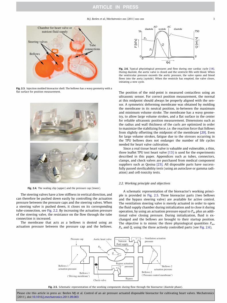
At the time of writing still research is being conducted to findthe optimal mechanical stimulation protocol for cultivating heartvalves. Therefore, the exact performance requirements are notyet known entirely, but three cardiac cycle quantities are thoughtto be important [18]. The pressure in the aorta (Pao), the left ventri-cle pressure (Plv) and the flow (Q) through the heart valve. Thepressure difference over the valve dP = Pao � Plv that builds upwhen the aortic valve closes is especially important to be imitatedcorrectly. The bioreactor must be able to handle both the cultivat-ing phase and the testing phase. During cultivation, the load on theheart valve is gradually increased as the tissue grows stronger,therefore setpoints and operating conditions are required to befully adjustable. For the testing phase, the bioreactor must be ableto handle large pressures and volume displacements up to 80 mLper cycle, and maximum flows of 600 mL s�1.
This paper is organized as follows: It first describes the biore-actor design, its working principle and the control objectives.Then the sensor and actuator choices are explained and eachactuator is assigned to a control objective. After laying out the to-tal control approach, each individual controller is designed andits performance is evaluated using experiments. Control of theflow through the heart valve, control of the pressure inside thebioreactor and control of the pressure drop over the heart valveare analyzed.
Fig. 2.2. Steering valves open position (left), closed position (right).
2. System set-up
For the bioreactor set-up description, a distinction is made be-tween disposable parts and reusable parts. Three separate dispos-able parts are injection molded (bioreactor shells, pressure capsand clips) [20]. The reusable part of the set-up includes the data
Please cite this article in press as: Beelen MJ et al. Control of an air pressure(2011), doi:10.1016/j.mechatronics.2011.09.003
acquisition system, sensors, actuators and the pneumatic system.Two identical bioreactor shells together with two pressure caps,clips, tubing and sensors compose the bioreactor assembly(Fig. 2.1). This assembly will be placed in its entirety inside anincubator.
2.1. Disposable parts
The bioreactor consists of two identical line-symmetric shells(Fig. 2.3) that are assembled together. A shell is fabricated usingtwo component injection molding on a Ferromatik K-tec 60 injec-tion molding machine. Each shell consists of a hard (polycarbon-ate (PC)) and soft component (thermoplastic polyurethane (TPU))and is molded using four injection shots in two mold positions,using a rotating mold. The soft component is used for the sealingbetween the two shells, for the membrane that acts as a bellowsto pump the fluid inside the bioreactor and for the steeringvalves (Fig. 2.2).
A pressure cap (Fig. 2.4) is mounted over the bellows and steer-ing valves, and is fixed using injection molded clips (Fig. 2.4). Theseclips are also used to fix the bioreactor shells together, and tofirmly close the chamber that is used to mount the heart valve inand the chamber for nutrient fluid supply. The parts in contactwith nutrient fluid have to be sterilized on beforehand, and dis-posed of after use. The sealing clip and pressure caps do not comein contact with the nutrient fluid, so strictly speaking, they can bereused.
actuated disposable bioreactor for cultivating heart valves. Mechatronics
Steering valves
Bellows
Tube connections
Chamber for heart valve or nutrient fluid supply
Fig. 2.3. Injection molded bioreactor shell. The bellows has a wavy geometry with aflat surface for position measurement.
Fig. 2.4. The sealing clip (upper) and the pressure cap (lower).
Fig. 2.6. Typical physiological pressures and flow during one cardiac cycle [18].During diastole, the aortic valve is closed and the ventricle fills with blood. Whenthe ventricular pressure exceeds the aortic pressure, the valve opens and bloodflows into the aorta (systole). When the ventricle has emptied, the valve closes,initiating a new cycle.
M.J. Beelen et al. / Mechatronics xxx (2011) xxx–xxx 3
The steering valves have a low stiffness in vertical direction, andcan therefore be pushed down easily by controlling the actuationpressure between the pressure caps and the steering valves. Whena steering valve is pushed down, it closes on its correspondingtube-connection, see Fig. 2.2. By increasing the actuation pressureof the steering valve, the resistance on the flow through the tubeconnection is increased.
The membrane that acts as a bellows is dented using anactuation pressure between the pressure cap and the bellows.
Bellows 1(‘Driving membrane’)
Pressure cap
By
Aortic heart valve
fl
Bellows 1 actuation pressure
Check-valve
Fig. 2.5. Schematic representation of the working componen
Please cite this article in press as: Beelen MJ et al. Control of an air pressure(2011), doi:10.1016/j.mechatronics.2011.09.003
The position of the mid-point is measured contactless using anultrasonic sensor. For correct position measurement, the normalat this midpoint should always be properly aligned with the sen-sor. A symmetric deforming membrane was obtained by moldingthe membrane in its neutral position, in-between the maximumand minimum volume stroke. The membrane has a wavy geome-try, to allow large volume strokes, and a flat surface in the centerfor reliable ultrasonic position measurement. Dimensions such asthe radius and wall thickness of the curls are optimized in orderto maximize the stabilizing force, i.e. the reaction force that followsfrom slightly offsetting the midpoint of the membrane [20]. Evenfor large volume strokes, fatigue due to the stresses occurring inthe TPU bellows does not endanger the number of life cyclesneeded for heart valve cultivation.
Since a real tissue heart valve is valuable and vulnerable, a thin,three leaflet TPU test heart valve [13] is used for the experimentsdescribed in this paper. Appendices such as tubes, connectors,clamps, and check valves are purchased from medical componentsuppliers such as Qosina [23]. All disposable parts have success-fully passed sterilizability tests (using an autoclave or gamma radi-ation) and cell-toxicity tests.
2.2. Working principle and objectives
A schematic representation of the bioreactor’s working princi-ple is provided in Fig. 2.5. Three bioreactor parts (two bellowsand the bypass steering valve) are available for active control.The ventilation steering valve is merely actuated in order to openthe fluid supply chamber during initialization and to close it duringoperation, by using an actuation pressure equal to Pao plus an addi-tional valve closing pressure. During initialization, fluid is ex-changed and the bellows are brought to their startup position.The objective is to mimic the three physiological quantities Pao,Plv and Q, using the three actively controlled parts (see Fig. 2.6).
Bypass
pass actuationpressure
Ventilation actuation pressure Nutrient
uid supply
Bellows 2actuation pressure
Bellows 2 (‘Pressure control membrane’)
ts during flow through the bioreactor (diastole phase).
actuated disposable bioreactor for cultivating heart valves. Mechatronics

-
- +-
-
Pressure drop over heart valve control loop Pressure control loop Position control loop
++
++
+
+
+
Fig. 2.7. Schematic control architecture.
4 M.J. Beelen et al. / Mechatronics xxx (2011) xxx–xxx
Bellows 1 lies in front of the heart valve, i.e. it simulates the leftventricle. Therefore, bellows 1 is assigned to control the volumedisplacement during systole (obtained by integrating the desiredsystolic flow), and to control the flow back through the bypass dur-ing diastole. The relation between the volume displacement of thebellows and the position of the surface midpoint of the bellows, i.e.the bellows indentation, is linear since it is described by a hemi-sphere that is deformed in vertical direction. Though this simpli-fied model does not take the wavy geometry into account,measurements have verified that the model provides an accuraterepresentation. Using this relationship the bellows displaced vol-ume is calculated from position measurements of the bellowsmid-point. The position controlled membrane is also referred toas the driving bellows.
Bellows 2 is not controlled on its position, but it is actuated tocontrol Pao. It will roughly move along with bellows 1. The functionof bellows 1 and 2 could be exchanged, but the above described ap-proach was chosen because it matches the working of the physio-logical heart.
During the systole, the check-valve prevents flow through thebypass. In this way, all fluid-medium displaced by bellows 1 isforced through the heart valve. During diastole, the aortic heartvalve closes, and the nutrient-fluid is pumped back to bellows 1(analogue to the left ventricle) through the bypass. The bypasssteering valve is not entirely opened, but in a controlled manner,in order to impose a resistance on this flow back (simulating thebody ‘impedance’). In this way a heart valve closing pressure dPis obtained.
2.3. Feedback system set-up
To achieve the above described working principle, a control sys-tem consisting of sensors and actuators is required.
The pressure difference before and after the heart valve is mea-sured using miniature reusable pressure transducers (Becton Dick-inson, model P10EZ), that have a pressure range of �4 to 40 kPaand an accuracy finer than 0.02 kPa. The sensors are mounted in-side a sterile disposable dome, in contact with a flexible membranethat transmits the pressure from inside the bioreactor to the sens-ing diaphragm of the transducer. This dome membrane provides asterile barrier between the transducer and the nutrient-fluid-filledchamber of the dome.
Position measurement of the bellows is done contactless, usingultrasonic sensors (Microsonic, model LPC-25) which have an accu-racy of 0.08 mm. They are mounted inside the injection moldedpressure caps, aligned with the surface normal of the bellows atthe mid-point location.
Air pressure actuation is performed via four electronic propor-tional air flow valves. Two different types are used, a proportionalpressure regulator (Festo, MPPES series) and a proportional direc-tional control valve (Festo, MPYE series). The MPPES has been de-signed for regulating the output pressure proportional to aspecified electrical nominal value, and therefore contains an inter-nal control circuit. Because the output pressures of these actuatorsare thus known, they are used to control the steering valves, sincethe desired actuation pressure is often a function of the internalpressure in the bioreactor. The MPYE air flow valves are used foractuating the bellows. In this case, the actuating pressure doesnot need to be known, since one of the control objectives is to po-sition one of the bellows, and another objective is to control theaortic pressure. The MPYE controls a valve opening (5/3-way func-tion) proportional to an input voltage. It has no internal pressurecontrol circuit. In this way, a fast and smooth step response is ob-tained. By connecting compressed air to one supply port and vac-uum air to another, we are able to push and pull on the bellows.
Please cite this article in press as: Beelen MJ et al. Control of an air pressure(2011), doi:10.1016/j.mechatronics.2011.09.003
The pneumatic system consists of the four before mentioned airflow valves, an air filter, tubing, air reservoirs (to provide a supplyof compressed air for fast pulses and to damp pressure fluctua-tions) and a vacuum pump (Vacuubrand, model ME-16) with10 m3/h suction capacity. The pump is also used to provide com-pressed air.
The real-time Data Acquisition (DAQ) system consists of a PCwith an internal multifunctional PCI DAQ card from NationalInstruments [19]. Using two connector blocks, all sensors and actu-ators are connected to this PCI card, and to a 24 V DC power supply.A Matlab-Simulink RTW [17] generated real time application isrunning with a sampling frequency of 1 kHz.
For visualization of the cultivating heart valve, a high speed col-or camera (Prosilica, model GC64OC) films through the transparentheart valve chamber of the bioreactor.
2.4. Rough sketch of the control approach
The inputs and outputs of the MIMO system are highly coupled.Actuating bellows 1 also results in a movement of bellows 2, and achange in the pressures. The position of the bypass steering valvestrongly influences the system response. Therefore decentralizedcontrol does not yield sufficient pressure tracking performance.The control approach developed for the bioreactor (introducedschematically in Fig. 2.7) is explained in the remainder of this sec-tion. Section 3 isolates a single bellows from the total system, toaddress stability and performance of the SISO position control loop,while Section 4 investigates the MIMO interactions and provides aMIMO stability analysis. The approach uses three control loops,and two Repetitive Controllers (RC). Note that the plant has four in-puts and four outputs (see Table 2.1). Since input u4 and output y4
are no part of any feedback loop (input u4 simply opens and closesthe supply chamber and output y4 is merely used to monitor bio-reactor leakage), the controller
CðsÞ ¼P1 þ I1=s 0 0�KcP1 I2=s 0
0 0 I3=s
264
375 ð2:1Þ
is of size 3 � 3 Herein, P1 and I1 are the proportional and integralgains of the position control loop, I2 and I3 are the integral gainsfor respectively the pressure control loop and the pressure dropover the heart valve control loop and Kc in the off-diagonal termis a factor for decoupling. More specifically, it compensates theinfluence from bellows 1 on the aortic pressure. This is the first oftwo measures taken to cope with the cross interactions. The othermeasure is to design the controllers such that the three controlloops act on different bandwidths.
actuated disposable bioreactor for cultivating heart valves. Mechatronics

Table 2.1Signals in control architecture.
References Actuator inputs Outputs
r1 Displaced volumebellows 1 (mL)
u1 Bellows 1 (V) y1 Displaced volumebellows 1 (mL)
r2 Pao (kPa) u2 Bellows 2 (V) y2 Pao (kPa)r3
* (kPa) u3 Bypass (kPa) y3 Plv (kPa)u4 Ventilation (kPa) y4 Displaced volume
bellows 2 (mL)
For simplicity we use kPa units for u3 and u4, since the output pressure of thesteering valve actuators is proportional to their input voltage.* is the minimum of Plv during the systolic phase.
M.J. Beelen et al. / Mechatronics xxx (2011) xxx–xxx 5
The following is a brief explanation of the MIMO controller de-sign as will be described and tested in more detail in Section 4. Tomake the first (position control) loop most dominant, the drivingbellows is controlled firmly at its desired position, by a SISO con-troller, achieving a bandwidth of 0.6 Hz. To counteract the influ-ence of bellows 1 on the aortic pressure, the non-equilibriumpart of the control action u1 multiplied by Kc is substracted fromthe actuator input for bellows 2. Due to this decoupling, the firstloop can be considered to be ideal and the pressure controllercan be designed as a SISO controller, which features a slow integralaction (bw � 0.3 Hz). The bypass control loop consists of a veryslow integral action (bw � 0.05 Hz), giving the first and secondloop time to adjust to the changing dynamics.
3. Bellows position control (SISO)
From a control point of view, the bellows is the most impor-tant component of the bioreactor. For the following experiment,the bioreactor is emptied from nutrient fluid, and opened to theoutside world, in order to isolate the behavior of the bellowsand eliminate cross influences. In this way, only the SISO positioncontrol loop is considered to develop an intuitive understanding.The objective of the experiment is to follow a position setpointbased on a cardiac cycle of 1 Hz, with a 40 mL stroke (see r1 inFig. 3.4).
The dynamic behavior of the bellows with its actuator is nonlin-ear, since the bellows’ stiffness is dependent on its indentation andthe actuator’s valve opening is related to flow instead of displacedvolume. Therefore, to identify Frequency Response Functions (FRF)
100 101-10
0
10
20
Mag
nitu
de (d
B)
100 101-200
0
200
Pha
se (o )
100 1010
0.5
1
Coh
eren
ce
Frequency (Hz)
Fig. 3.1. Measured FRFs for the isolated bellows, from u1 (V) to the displacedvolume y1 (mL), around several volumes y1 2 (�40, 40) mL.
Please cite this article in press as: Beelen MJ et al. Control of an air pressure(2011), doi:10.1016/j.mechatronics.2011.09.003
from the actuator input u1 to the position y1 of the bellows, smallactuator valve movements around its mid-position are consideredand the bellows is perturbed around a number of different bellowspositions y1, see Fig. 3.1. The FRF resulting from perturbationsaround y1 = 0 mL (the neutral position), has the highest magnitude,while the FRFs around |y1| = 40 mL have the lowest magnitude. Themaximum difference in magnitude is around a factor 1.2. There-fore, for control design, we regard the bellows behavior as linear.Based on the FRF around y1 = 0 mL, (the bellows is usually movingaround its neutral position), we start by tuning a Proportional-Inte-gral (PI) controller using loop-shaping, in order to obtain an openloop with a cross-over frequency of 1 Hz. The bode diagram ofthe open loop (Fig. 3.2) shows a 61� phase margin at this frequency.The PI controller is preferred above a PID controller, since the 61�phase margin is sufficient and no extra phase lead from derivativecontrol is required. Moreover, adding derivative gain would highlyamplify measurement noise due to non-smooth positionmeasurements.
From the Nyquist diagram (Fig. 3.3), a gain margin of 5.3 and amodulus margin of 1.5 follow, hence the closed loop is stable. Thecontroller parameters, (P, I) = (0.085, 0.04), are implemented andtested, see Fig. 3.4a.
The setpoints in the control problem are repetitive. Thereforethe error shows similar behavior every cycle. This a priori knowl-edge of the error is used to further improve performance. A Repet-itive Control (RC) approach [12] is introduced, that aims atreducing the error by entirely eliminating its repetitive part, leav-ing only the non-repetitive part of the error. The RC approach ispreferred above an Iterative Learning Controller [1,6], since the ini-tial conditions are not the same each cycle, but depend on the pre-vious cycle. When setpoints are adjusted, the RC signal has to bereestablished. It is not convenient to update the RC signal offline,since restarting the system is not an option while cultivating heartvalves. The solution is to implement an on-line updating repetitivecontroller, as is depicted in Fig. 3.5. Herein, c 2 (0, 1) is the learningrate, L(s) is the learning filter, Q(s) is the robustness filter, Tc is thecycle time and Td is the time-delay in the system response. Therepetitive controller uses a memory loop that matches the cycletime, which is exactly known since the cardiac cycle frequency isdefined by the user (0.1 up to 10 Hz). Since the process has a rela-tively long time-delay Td (about 70 ms), the repetitive controlstructure provides a phase lead [25], by injecting the RCsignal f(t) Td milliseconds earlier. When this lag would not becompensated, the error at the current time instant would be used
100 101-25
-20
-15
-10
-5
0
5
Mag
nitu
de (d
B)
100 101-200
-100
0
100
200
Frequency (Hz)
Pha
se (o )
Fig. 3.2. Bode plot of the open loop, based on the FRF around the bellows neutralposition.
actuated disposable bioreactor for cultivating heart valves. Mechatronics

-1 -0.8 -0.6 -0.4 -0.2 0 0.2-1.4
-1.2
-1
-0.8
-0.6
-0.4
-0.2
0
0.2
Real Axis
Imag
inar
y Ax
is
Fig. 3.3. Nyquist diagram. The arrow denotes the increasing frequency from 0.5 Hzto 10 Hz.
167 167.5 168 168.5
-20
-10
0
10
20
Time ( )
Dis
plac
ed v
olum
e (
)
193 193.5 194 194.5
PI-controller PI-controller + RC
(a) (b)Time ( )
Fig. 3.4. Position control experiments using the isolated bellows 1. Repetitiveerrors in (a) are suppressed using the RC in (b).
6 M.J. Beelen et al. / Mechatronics xxx (2011) xxx–xxx
to calculate the next RC output. However, due to the time lag phe-nomenon, the actual system output will be affected only after atime delay duration. This will typically result in large or evendivergent tracking errors, even if a small learning gain c is used.
The learning filter is based on the inverse of the process sensi-tivity Ps(s) for optimal convergence speed as the implementationadds the RC signal to the controller output. The most importantfrequencies that we want to suppress are in the region between1 Hz and 5 Hz. The process sensitivity is approximately constant(20 dB) in this region, and decreases 80 dB per decade at higher fre-quencies. To prevent amplification of unwanted higher frequen-cies, a constant learning filter L = 0.1 is used. The learning ratec = 0.3 causes the system to establish a converged RC signal withina few setpoint cycles. This constant gain does not attenuate higherfrequencies, therefore a robustness filter Q(s) is designed, consist-
++
Fig. 3.5. Repetitive control structure incorporating time-delay compensation(similar to [25, Fig. 6]).
Please cite this article in press as: Beelen MJ et al. Control of an air pressure(2011), doi:10.1016/j.mechatronics.2011.09.003
ing of a first order low pass filter with a cut-off frequency at30 Hz, in order to satisfy the convergence criterion|Q(s)(1 � cLPs(s))| < 1 for all frequencies. The robustness filter al-lows constant updating of the RC signal, with the tradeoff that highfrequency repetitive errors are not eliminated. The low frequentrepetitive errors are eliminated by the RC, reducing the maximumerror with a factor 7, see Fig. 3.4b.
Other feedforward control actions, e.g. for eliminating frictionor inertia effects, only improve performance when no RC is used.When the RC is enabled in combination with the PI-controller, itprovides all feedforward control action needed and other feedfor-wards do not improve performance anymore.
4. Pressure control (MIMO)
Filling the bioreactor with water to simulate nutrient fluid andclosing it to the outside world (using the ventilation steering valve)restores the interactions in the MIMO system and it allows forinternal bioreactor pressure control.
Only the entries from the MIMO plant that correspond to inputsu1 and u2 are identified, since entries corresponding to u4 are nopart of any feedback loop and the entries corresponding to u3 arehighly nonlinear and no reliable FRF measurements are possible.To explain this nonlinearity we make the following observations.When the output pressure of the bypass steering valve actuatoris approximately 6 kPa higher than the internal bioreactor pressure(Pao), the stiffness of the steering valve is overcome and the valve ispushed down on its opposite tube connection. Increasing the actu-ation pressure results in a closing pressure that imposes a resis-tance on the backflow _y < 0 through the bypass, obtaining aheart valve closing pressure dP = Pao � Plv during diastole. There-fore, the influence of u3 on the outputs dependents on:
� The (intrinsically time variant) closing properties of the tissueheart valve, e.g. without a tissue (or artificial) heart valve, nopressure drop is possible.� The magnitude of the flow through the bypass, e.g. when
_y1 � 0mL=s there is no flow to impose a resistance on (notethe check-valve in Fig. 2.5).� The pressure difference u3 � y2, e.g. the bypass is entirely open
when u3 � y2 is smaller than the additional valve closing pres-sure needed to overcome the stiffness of the steering valve,while the bypass is entirely closed when u3 � y2 is larger thanthe actuation pressure needed to entirely close the steeringvalve on its opposite tube ending. In both of these cases theinfluence of u3 is negligible.
For the bypass control loop, a very slow integral action is suffi-cient, since it merely aims at controlling the extremum . For thisreason we assume the bypass actuation pressure is constant, andconsider 2 � 2 plants for two extreme cases of bypass actuation:Ho(s) represents the situation when the bypass is completely open(u3 = 0) and Hc(s) is the plant in case the bypass steering valve isactuated with the maximum actuation pressure which will everoccur (u3 = 21 kPa).
To identify these two MIMO plant behaviors, a noise and a chirpsignal is injected in inputs u1 and u2, and outputs y1 and y2 aremeasured in an experiment. The transfer functions from the corre-sponding plant entries are calculated. The plant entry Hij denotesthe transfer from input uj to output yi. The plant is nonlinear, there-fore perturbations around different operating points are consid-ered. The FRFs displayed in Fig. 4.1 resemble linearized plantswhere both bellows move around their neutral position, whilethe internal bioreactor pressures fluctuate around 12 kPa (averageof the physiological pressure). The steering valve from the bypass
actuated disposable bioreactor for cultivating heart valves. Mechatronics

-20
-10
0
10
20
Mag
nitu
de (d
B)
-200
-100
0
100
200
Phas
e (o )
Frequency (Hz)
-10
0
10
20
30
Mag
nitu
de (d
B)-200
-100
0
100
200
Phas
e (o )
Frequency (Hz)
Ho11 Ho
12 Hc11 Hc
12 Ho21 Ho
22 Hc22 Hc
22(a)
100 101100 101
100 101 100 101
(b)
Fig. 4.1. FRF measurements around the operating point y1 = y4 = 0 mL, y2 = y3 = 12 kPa, for the 2 � 2 systems Hc and Ho, from u1 and u2 (V) to the volume y1 (mL) (a) and to thepressure.
1000.2
0.3
0.4
0.5
0.6
0.7
0.8
Frequency (Hz)
RG
A
RGAo11
RGAo12
RGAc11
RGAc12
101
Fig. 4.2. Diagonal (solid) and off-diagonal (dashed) RGA elements, indicating thepreferred diagonal pairing and the cross interactions in the 2 � 2 plants Ho(s) andHc(s).
M.J. Beelen et al. / Mechatronics xxx (2011) xxx–xxx 7
is kept open to identify Hoij and entirely closed to identify Hc
ij. Aftermeasuring and comparing FRFs at other operating points, we con-clude that the nonlinear behavior is small enough (similar toFig. 3.1) to be able to design linear controllers based on these FRFs.The Relative Gain Array (RGA), calculated for both Ho(s) and Hc(s),is used to visualize the interactions in Fig. 4.2. The diagonal RGAelements (solid lines) are closer to one compared to the off-diago-nal elements (dashed lines), indicating the preferred diagonal pair-ing. For low frequencies (<2 Hz) this preference is less evident dueto the high coupling between inputs.
The position controller is designed using SISO loopshaping(bw � 0.6 Hz), based on Ho
11, resulting in (P1, I1) = (0.09, 0.02). Therepetitive controller for the position is designed as described in Sec-tion 3, with L(s) and Q(s) adjusted based on Ho
11 and this new PI-controller.
The decoupling factor is tuned using the ratio of magnitudes ofthe direct and cross transfer function for the aortic pressure at thebandwidth of the pressure control loop
Kc ¼ 0:93 � jHo21ð0:6pjÞj=jHo
22ð0:6pjÞj; ð4:1Þ
since it provides an estimation of the influence ratio of bellows 1and bellows 2 on the aortic pressure. The output from F1 is alsocompensated using Kc, as visualized in Fig. 2.7. After this decou-pling, the integral action to obtain the correct pressure level istuned (I2 = 0.04). The repetitive controller F2 for the aortic pressureis designed similar to F1, as described in Section 3.
The MIMO Nyquist plot (Fig. 4.3) shows that the designed 2 � 2feedback controller
C2ðsÞ ¼P1 þ I1=s 0�KcP1 I2=s
� �¼
0:09þ 0:02=s 0�0:084 0:02=s
� �ð4:2Þ
results in a stable closed loop for both the case of an open and aclosed bypass, since |I + C2(jx)Ho(jx)| and |I + C2(jx)Hc(jx)| do notencircle the origin. Closed loop stability in these extreme casesand the fact that the bypass actuation pressure changes very slowly,do however not provide a full guarantee that the closed loop will be
Please cite this article in press as: Beelen MJ et al. Control of an air pressure(2011), doi:10.1016/j.mechatronics.2011.09.003
stable for bypass actuation pressures in between 0 kPa and 21 kPa,but from experiments we have found no reason to expect any trou-ble. Moreover, the bypass steering valve is considered passive andwill, by itself, not contribute to the instability of the system. Thesearguments make full system stability plausible, which is sufficientfor the scope of this research, i.e. achieving all necessary functional-ity for cultivating heart valves. A more conclusive mathematicalanalysis will be the subject of future research.
4.1. Aortic pressure control experiments
For the remaining pressure control experiments, the drivingbellows is position controlled on the 40 mL cardiac setpoint of
actuated disposable bioreactor for cultivating heart valves. Mechatronics

-0.2 0 0.2 0.4 0.6 0.8 1 1.2 1.4 1.6-1.2
-1
-0.8
-0.6
-0.4
-0.2
0
0.2
0.4
Real Axis
Imag
inar
y Ax
is
|I+C(jω)Ho(jω)|
|I+C(jω)Hc(jω)|Bypass open
Bypass closed
Fig. 4.3. The MIMO Nyquist showing stability for both bypass steering valveactuation cases.
8 M.J. Beelen et al. / Mechatronics xxx (2011) xxx–xxx
Fig. 3.4, using the P1 + I1/s and F1 controller designed in the previ-ous section. The resulting tracking performance is slightly deterio-rated compared to Fig 3.5b.
To show the cross influence of u1 on y2 and y4 in the time do-main, the first bellows is position controlled while the second bel-lows is not actuated. Fig. 4.4 shows the second bellows dancingalong with (the negative of) the movement of the first bellows.The response of Pao ranges from 0 kPa to 26 kPa.
Next, the controller (4.2) is implemented, but without F2, to tryto control the pressure on a constant setpoint of 12 kPa. Fig. 4.5a
0 0.5 1 2-30
-20
-10
0
10
20
Time (s)
Dis
plac
ed v
olum
e be
llow
s 2
(mL)
1.5
Fig. 4.4. The position of bellows 2 (left) and pressure (righ
0 0.50
5
10
15
20
Tim
(a) r2(t)
0 0.5 1 1.5 20
5
10
15
20
Aorti
c pr
essu
re (k
Pa)
Time (s)
Aorti
c pr
essu
re (k
Pa)
(b)
Fig. 4.5. Control of Pao, with Kc = 0.93 (a), Kc = 0
Please cite this article in press as: Beelen MJ et al. Control of an air pressure(2011), doi:10.1016/j.mechatronics.2011.09.003
shows that the decoupling factor Kc = 0.93 is able to reduce theinfluence from bellows 1 on the aortic pressure with a factor 9.
For the following experiment the objective is to control thepressure to follow the cardiac setpoint that ranges between10 kPa and 16 kPa. Decreasing Kc results in the second bellowsmoving along with the first, but with a smaller amplitude than be-fore, restoring part of the interaction. The desired amplitude is ob-tained with Kc = 0.68, see Fig. 4.5b. A profile in the aortic pressurearises naturally, with a shape resembling the cardiac cycle. En-abling the RC algorithm that works on the pressure error e2, signif-icantly reduces the error, i.e. |e2| < 1.1 kPa, see Fig. 4.5c. Thisexperiment validates the described control approach, which provesto achieve a smooth pressure tracking performance (while the by-pass steering valve is not actuated).
4.2. Pressure drop over heart valve control experiments
The bypass steering valve is used to bring the minimum of Plv
during the diastolic phase ( ) down to a predefined value (often0 kPa), since decreasing increases dP when Pao is controlled cor-rectly. The magnitude of this pressure drop is an important controlobjective since this is the force imposed on the tissue.
Continuing with the previous experiment, the bypass steeringvalve is actuated (I3 = 0.003) in order to bring to zero, and a pres-sure drop over the heart valve arises successfully, see Fig. 4.6b. Asdescribed at the start of this chapter, this pressure drop is highlydependent on the closing characteristics of the tissue (or in thiscase TPU) heart valve.
Care has to be taken with the pressure repetitive controller, be-cause RC signal convergence can be endangered by model uncertain-ties. The pressure oscillation at the end of the systolic phase is anatural reaction due to the closing of the heart valve and therefore
0
5
10
15
20
25
30
Time (s)0 1 2
Aorti
c pr
essu
re (k
Pa)
0.5 1.5
t) responses due to the position controlled bellows 1.
0 0.5 1 1.5 20
5
10
15
20
Time (s)1 1.5 2
e (s)
y2(t)
Aorti
c pr
essu
re (k
Pa)
(c)
.68 (b) and enabling the RC algorithm (c).
actuated disposable bioreactor for cultivating heart valves. Mechatronics

0 0.5 1 1.5 2-5
0
5
10
15
20
Pres
sure
(kPa
)
Time (s)
y3(t) y2(t)-y3(t)
0 0.5 1 1.5 2-5
0
5
10
15
20Ao
rtic
pres
sure
(kPa
)
Time (s)
r2(t) y2(t)
Strong RC
Weak RC
RC off
(a) (b)
Fig. 4.6. The cardiac pressures Pao (a), Plv and dP (b), during an experiment with a 40 mL volume stroke, using an RC controller whose learning rate changes depending on thecardiac phase.
Table 4.1Maximum errors for various strokes.
Stroke (mL) Max|e1| (mL) Max|e2| (kPa)
RC on RC off
20 1.3 0.6 1.140 1.6 0.8 1.460 2.1 1.1 2.280 7.7 4.4 5.0
M.J. Beelen et al. / Mechatronics xxx (2011) xxx–xxx 9
not necessary to suppress. For this reason, the RC algorithm is en-abled, but only at the remaining part of the signal, denoted by theshading in Fig. 4.6a. The RC needs to be stronger (in terms of learningrate and Q(s) cut-off frequency) in the systolic phase than in the dia-stolic phase, because the resistance of the bypass on the flow duringdiastole causes pressure oscillations that are hard to suppress. Thenegative peak (approximately �3 kPa) in the pressure difference isneeded to unfold and open the test valve from its firmly closed posi-tion. This also is typical for the TPU test valve used. So far the switch-ing of the RC has caused no undesired artifacts in experiments, butwill need to be investigated more closely in future research.
Similar experiments are performed with stroke volumes of 20,60 and 80 mL. An overview of the maximum errors is provided inTable 4.1.
5. Implementation issues
The delay in the system is considerable (0.12 s), due to thephase delay of the controller, the dynamics of the sensor, actuator,electronics and the pneumatic system, which is clearly seen inFig. 3.4a. It is not important at what time the system produces acertain output, as long as it resembles the cardiac conditions.Therefore, the system is allowed to have this delay. The errore1(t) = y1(t) � r1(t) is large, but the error ~e1ðtÞ that is based on a de-layed reference signal ~r1ðtÞ is much smaller. The reference~r1ðtÞ ¼ r1ðt � s1ðtÞÞ results from delaying the original referencewith s1(t) seconds. This variable delay is estimated on-line, in orderto optimally fit the new reference on the measurements, i.e. tominimize ~e1ðtÞ. This is done by subdividing the setpoint in strictlymonotonically increasing parts, and strictly monotonicallydecreasing parts. During increasing parts, when the shifted refer-ence ~r1ðtÞ is above (below) the measured signal, the delay s1(t) isincreased (decreased). Vice versa for decreasing parts.
Since the RC updates online, it should be disabled during set-point changes, for instance during system startup, setpoints arebuild up gradually. When reaching steady state, the RC enables
Please cite this article in press as: Beelen MJ et al. Control of an air pressure(2011), doi:10.1016/j.mechatronics.2011.09.003
and the update of the RC signal has to restart. The RC will forcethe delay out of the system within a few setpoint cycles. Thisaggressive change in system operation is unwanted and thereforethe RC is based on the delayed reference signal ~r1ðtÞ. In this way,the RC makes only minor changes when enabled, and the delays1(t) can be forced to zero in a longer, predefined timespan. Duringthis transition, the RC takes over the largest part of the control ac-tion since it entirely predicts the control signal, while the PI con-troller acts on the non-repetitive disturbances. This approach issimilar to a Phase Locked Loop (PLL) since the reference ~r1ðtÞ iskept in phase with the output y1(t).
Full adjustment of the volume setpoint (both stroke and profile)and pressure setpoints (amplitude, bias and profile) is allowed.Also the cycle frequency and the desired pressure difference canbe changed. Therefore the bioreactor has the functionality to alsocultivate other heart valves such as the tricuspid or mitral valve,since the required operating conditions are less demanding com-pared to the testing phase of the aortic valve. The controller param-eters are varying with changing setpoint combinations to achievesatisfactory performance.
6. Conclusion
This paper presented an air pressure actuation system for anewly developed disposable bioreactor [20] that is both accurateand reliable. The control system enables the bioreactor to achievea satisfactory position and pressure tracking performance, forstrokes up to 80 mL. The bioreactor setup is the first in literatureto achieve all necessary functionality for cultivating heart valvesduring the growing, conditioning and testing phase and is compactenough to easily fit inside an incubator.
Four mobile stand-alone bioreactor setups are available for lab-oratories that are performing research on cultivating heart valves.One of them is presently being used in ‘cellab’ [4], in the Biome-chanics & Tissue Engineering group at the TU/e.
Some future work will target at extending the gain schedulingapproach, to improve performance for 80 mL volume strokes andhigh cardiac frequencies such as 10 Hz (for advanced tissue test-ing). Also, system operation will need to automatically adjust tothe tissue properties, such as the heart valve deformation esti-mated online using the high speed camera. In this work, closedloop stability has only been addressed for the extreme cases ofeither a fully closed or fully opened bypass steering valve. There-fore the challenge remains to provide a conclusive stability analy-sis with regard to bypass actuation in-between 0 kPa and 21 kPa.
actuated disposable bioreactor for cultivating heart valves. Mechatronics

10 M.J. Beelen et al. / Mechatronics xxx (2011) xxx–xxx
Acknowledgment
The authors gratefully acknowledge the support and fundingprovided by Prof. H.E.H. Meijer.
References
[1] Ahn H, Chen CK, Moore KL. Iterative learning control: brief survey andcategorization. IEEE Trans Syst Man Cybern Part C Appl Rev 2007;37(6).
[2] Baaijens FPT, Bouten CVC, Mol A, Rutten MCM, Hoerstrup SP. European and USpatent 0 145 920 A1; 2008.
[3] Banerjee AG et al. Incorporating manufacturability considerations duringdesign of injection molded multi-material objects. Res Eng Des2007;17:207–31. doi:10.1007/s00163-007-0027-.
[4] Biomechanics and Tissue Engineering, Eindhoven University of Technology;2010. <www.mate.tue.nl/mate/research/index.php/2>.
[5] Biomedical brochure. Tissue engineered heart valve; 2007. <www.tue.nl>.[6] Chen CK, Hwang J. Iterative learning control for position tracking of a
pneumatic actuated X–Y table. Control Eng Pract 2005;13(12):1455–61.[7] Driessen Mol A et al. Tissue engineering of semi-lunar heart valves, current
status and future developments. J Heart Valve Dis 2004;13:272–80.[8] Driessen Mol A et al. Tissue engineering of human heart valve leaflets: a novel
bioreactor for a strain-based conditioning approach. Ann Biomed Eng2005;33:1778–88. doi:10.1007/s10439-005-8025-4 PMid:1638952.
[9] Dumont K et al. Design of a new pulsatile bioreactor for tissue engineeredaortic heart valve formation. Artif Organs 2002;26(8):703–33. doi:10.1046/j.1525-1594.2002.06931_3.x [PMid:1213949, Eindhoven University ofTechnology, Eindhoven, The Netherlands].
[10] Elizondo DR, Campbell TD, Totten RP. US patent 6 174 719 B1; 2001.
Please cite this article in press as: Beelen MJ et al. Control of an air pressure(2011), doi:10.1016/j.mechatronics.2011.09.003
[11] Goldstein S, Black KS. US patent 5 899 937; 1999.[12] Hara S, Yamamoto Y, Omata T, Nakano M. Repetitive control system: a new
type servo system for periodic exogenous signals. IEEE Trans Autom Control1988;7:659–68.
[13] HemoLab BV. Three leaflet TPU heart valve; 2009.[14] Hoerstrup SP et al. New pulsative bioreactor for in vitro formation of tissue
engineered heart valves. Tissue Eng 2000;1(6):75–9. doi:10.1089/107632700320919 PMid:1094120.
[15] Hoerstrup SP et al. Functional living trileaflet heart valves grown in vitro.Circulation 2000;102(19):;44–49.
[16] Kok T. Control engineering of a disposable bioreactor. Master thesis, DCT2007.031, Eindhoven University of Technology, Eindhoven, The Netherlands;2007.
[17] The MathWorks. Real-time windows target 3.5. <www.mathworks.com>.[18] Mol A. Functional tissue engineering of human heart valve leaflets. PhD thesis,
Eindhoven University of Technology, Eindhoven, The Netherlands; 2005.[19] National Instruments. Multifunction data acquisition model PCI-6229; 2010.
<www.ni.com>.[20] Neerincx PE, Meijer HEH. Design, realization and optimization of a disposable
bioreactor for growing, culturing and testing of tissue-engineered heart valves.Int Polym Proc 2010;25(2):1–10.
[21] Neerincx PE, Meijer HEH. Device in which to subject an implantable medicalproduct to loads. World patent WO/2010/024669; 2010.
[22] Peterson A, Landeen LK, Bennett J, Gee J, Chesla S, Zeltinger J. US patent1998;5:846–28.
[23] Qosina. Disposable components; 2010. <www.qosina.com>.[24] Rutten MCM et al. The valve exerciser: a novel bioreactor for physiological
loading of tissue-engineered aortic valves. J Biomech 2005;32:1039–49.[25] Tan KK, Zhao S, Huang S, Lee TH. A new repetitive control for LTI systems with
input delay. J Process Contr 2009;19(4):711–6.
actuated disposable bioreactor for cultivating heart valves. Mechatronics