Control Engineering Practice - People @ EECS at UC Berkeleytomlin/papers/HHWT11.pdf · Precision...
14
Precision flight control for a multi-vehicle quadrotor helicopter testbed Gabriel M. Hoffmann a,1 , Haomiao Huang a, ,1 , Steven L. Waslander b,1 , Claire J. Tomlin c a Aeronautics and Astronautics, Stanford University, Stanford, CA 94305, United States b Department of Mechanical and Mechatronics Engineering, University of Waterloo, Waterloo, ON, Canada N2L 3G1 c Electrical Engineering and Computer Sciences, University of California Berkeley, Berkeley, CA 94708, United States article info Article history: Received 10 September 2010 Accepted 10 April 2011 Available online 23 June 2011 Keywords: Quadrotor helicopters Unmanned aerial vehicles Flight control Quadrotor aerodynamics abstract Quadrotor helicopters continue to grow in popularity for unmanned aerial vehicle applications. However, accurate dynamic models for deriving controllers for moderate to high speeds have been lacking. This work presents theoretical models of quadrotor aerodynamics with non-zero free-stream velocities based on helicopter momentum and blade element theory, validated with static tests and flight data. Controllers are derived using these models and implemented on the Stanford Testbed of Autonomous Rotorcraft for Multi-Agent Control (STARMAC), demonstrating significant improvements over existing methods. The design of the STARMAC platform is described, and flight results are presented demonstrating improved accuracy over commercially available quadrotors. & 2011 Elsevier Ltd. All rights reserved. 1. Introduction Quadrotor helicopters are an increasingly popular rotorcraft concept for unmanned aerial vehicle (UAV) platforms. These vehicles use two pairs of counter-rotating, fixed-pitch rotors located at the four corners of the aircraft, as shown in Fig. 1. Their use as autonomous platforms has been envisaged in a variety of applications, both as individual vehicles and in multiple vehicle teams, including surveillance, search and rescue, and mobile sensor networks (Hoffmann, Waslander, & Tomlin, 2006b). Recent interest in the quadrotor design from numerous communities, including research, surveillance, construction and police use (Hull, 2010), can be linked to two main advantages over comparable vertical take off and landing (VTOL) UAVs, such as helicopters. First, quadrotors can use fixed-pitch rotors and direct control of motor speeds for vehicle control, simplifying design and maintenance by eliminating complex mechanical control linkages for rotor actuation. Second, the use of four rotors ensures that individual rotors are smaller than the equivalent main rotor on a helicopter for a given airframe size. The smaller rotors store less kinetic energy during flight and can be enclosed within a protec- tive frame, permitting flights indoors and in obstacle-dense environments with reduced risk of damage to the vehicles, their operators, or surroundings. These added safety benefits greatly accelerate the design and test flight process by allowing testing to take place indoors or out, by inexperienced pilots, and with a short turnaround time for recovery from incidents. As a result of these advantages, there have been a number of commercial (Aeryon Labs Inc., 2009; Ascending Technologies GmbH, 2008; DraganFly-Innovations, 2009; Microdrones GmbH, 2008) and research (Achtelik, Bachrach, He, Prentice, & Roy, 2009; Lupashin, Sch ¨ ollig, Sherback, & D’Andrea, 2010; Michael & Fink, 2009; Valenti, Bethke, Fiore, How, & Feron, 2006) quadrotor platforms developed. However, there has been relatively little development of accurate dynamics models of quadrotors for operating at higher speeds and in outdoor environments. Such models and control techniques based upon the models are critical for precision control and trajectory tracking. The main contribu- tions of this work are the presentation of aerodynamic models for quadrotors and the use of these models in the development of a quadrotor platform (the Stanford Testbed of Autonomous Rotor- craft for Multi-Agent Control, or STARMAC) capable of achieving the sub-meter positioning precision necessary to fly multiple vehicles in a confined area with substantial motion. STARMAC has been developed to take advantage of the benefits of quadrotors, with the aim of being an easy-to-use and reconfigurable proving ground for novel algorithms for multi-agent applications. It is currently comprises six STARMAC II quadrotors. These vehicles have been used to demonstrate a variety of algorithms, including experi- ments for collision avoidance (Waslander, Inalhan, & Tomlin, 2004; Waslander & Tomlin, 2010), information-theoretic control for cooperative search (Hoffmann & Tomlin, 2010; Hoffmann, Waslander, & Tomlin, 2006a), dynamically feasible trajectory generation (Vitus, Pradeep, Hoffmann, Waslander, & Tomlin, 2008, 2010), and verifica- tion of provably safe aerobatic maneuvers (Gillula, Huang, Vitus, & Tomlin, 2010). In each case, the flexibility and convenience of the Contents lists available at ScienceDirect journal homepage: www.elsevier.com/locate/conengprac Control Engineering Practice 0967-0661/$ - see front matter & 2011 Elsevier Ltd. All rights reserved. doi:10.1016/j.conengprac.2011.04.005 Corresponding author. E-mail addresses: [email protected] (G.M. Hoffmann), [email protected] (H. Huang), [email protected] (S.L. Waslander), [email protected] (C.J. Tomlin). 1 These authors contributed equally to this work. Control Engineering Practice 19 (2011) 1023–1036
Transcript of Control Engineering Practice - People @ EECS at UC Berkeleytomlin/papers/HHWT11.pdf · Precision...

Control Engineering Practice 19 (2011) 1023–1036
Contents lists available at ScienceDirect
Control Engineering Practice
0967-06
doi:10.1
� Corr
E-m
haomia
tomlin@1 Th
journal homepage: www.elsevier.com/locate/conengprac
Precision flight control for a multi-vehicle quadrotor helicopter testbed
Gabriel M. Hoffmann a,1, Haomiao Huang a,�,1, Steven L. Waslander b,1, Claire J. Tomlin c
a Aeronautics and Astronautics, Stanford University, Stanford, CA 94305, United Statesb Department of Mechanical and Mechatronics Engineering, University of Waterloo, Waterloo, ON, Canada N2L 3G1c Electrical Engineering and Computer Sciences, University of California Berkeley, Berkeley, CA 94708, United States
a r t i c l e i n f o
Article history:
Received 10 September 2010
Accepted 10 April 2011Available online 23 June 2011
Keywords:
Quadrotor helicopters
Unmanned aerial vehicles
Flight control
Quadrotor aerodynamics
61/$ - see front matter & 2011 Elsevier Ltd. A
016/j.conengprac.2011.04.005
esponding author.
ail addresses: [email protected] (G.M
[email protected] (H. Huang), stevenw@uwater
eecs.berkeley.edu (C.J. Tomlin).
ese authors contributed equally to this work
a b s t r a c t
Quadrotor helicopters continue to grow in popularity for unmanned aerial vehicle applications.
However, accurate dynamic models for deriving controllers for moderate to high speeds have been
lacking. This work presents theoretical models of quadrotor aerodynamics with non-zero free-stream
velocities based on helicopter momentum and blade element theory, validated with static tests and
flight data. Controllers are derived using these models and implemented on the Stanford Testbed of
Autonomous Rotorcraft for Multi-Agent Control (STARMAC), demonstrating significant improvements
over existing methods. The design of the STARMAC platform is described, and flight results are
presented demonstrating improved accuracy over commercially available quadrotors.
& 2011 Elsevier Ltd. All rights reserved.
1. Introduction
Quadrotor helicopters are an increasingly popular rotorcraftconcept for unmanned aerial vehicle (UAV) platforms. Thesevehicles use two pairs of counter-rotating, fixed-pitch rotorslocated at the four corners of the aircraft, as shown in Fig. 1.Their use as autonomous platforms has been envisaged in avariety of applications, both as individual vehicles and in multiplevehicle teams, including surveillance, search and rescue, andmobile sensor networks (Hoffmann, Waslander, & Tomlin, 2006b).
Recent interest in the quadrotor design from numerouscommunities, including research, surveillance, construction andpolice use (Hull, 2010), can be linked to two main advantages overcomparable vertical take off and landing (VTOL) UAVs, such ashelicopters. First, quadrotors can use fixed-pitch rotors and directcontrol of motor speeds for vehicle control, simplifying design andmaintenance by eliminating complex mechanical control linkagesfor rotor actuation. Second, the use of four rotors ensures thatindividual rotors are smaller than the equivalent main rotor on ahelicopter for a given airframe size. The smaller rotors store lesskinetic energy during flight and can be enclosed within a protec-tive frame, permitting flights indoors and in obstacle-denseenvironments with reduced risk of damage to the vehicles, theiroperators, or surroundings. These added safety benefits greatlyaccelerate the design and test flight process by allowing testing to
ll rights reserved.
. Hoffmann),
loo.ca (S.L. Waslander),
.
take place indoors or out, by inexperienced pilots, and with a shortturnaround time for recovery from incidents.
As a result of these advantages, there have been a number ofcommercial (Aeryon Labs Inc., 2009; Ascending TechnologiesGmbH, 2008; DraganFly-Innovations, 2009; Microdrones GmbH,2008) and research (Achtelik, Bachrach, He, Prentice, & Roy, 2009;Lupashin, Schollig, Sherback, & D’Andrea, 2010; Michael & Fink,2009; Valenti, Bethke, Fiore, How, & Feron, 2006) quadrotorplatforms developed. However, there has been relatively littledevelopment of accurate dynamics models of quadrotors foroperating at higher speeds and in outdoor environments. Suchmodels and control techniques based upon the models are criticalfor precision control and trajectory tracking. The main contribu-tions of this work are the presentation of aerodynamic models forquadrotors and the use of these models in the development of aquadrotor platform (the Stanford Testbed of Autonomous Rotor-craft for Multi-Agent Control, or STARMAC) capable of achievingthe sub-meter positioning precision necessary to fly multiplevehicles in a confined area with substantial motion.
STARMAC has been developed to take advantage of the benefits ofquadrotors, with the aim of being an easy-to-use and reconfigurableproving ground for novel algorithms for multi-agent applications. It iscurrently comprises six STARMAC II quadrotors. These vehicles havebeen used to demonstrate a variety of algorithms, including experi-ments for collision avoidance (Waslander, Inalhan, & Tomlin,2004; Waslander & Tomlin, 2010), information-theoretic control forcooperative search (Hoffmann & Tomlin, 2010; Hoffmann, Waslander,& Tomlin, 2006a), dynamically feasible trajectory generation (Vitus,Pradeep, Hoffmann, Waslander, & Tomlin, 2008, 2010), and verifica-tion of provably safe aerobatic maneuvers (Gillula, Huang, Vitus, &Tomlin, 2010). In each case, the flexibility and convenience of the

G.M. Hoffmann et al. / Control Engineering Practice 19 (2011) 1023–10361024
quadrotor design in general and the precision flight capabilities ofSTARMAC in particular have enabled rapid evaluation of newtechnologies.
In this work, aerodynamic models of quadrotor helicopters aredeveloped, based on well established research for helicopteraerodynamics (Leishman, 2000; Newman, 1994; Prouty, 1990),including the effects of angle of attack and speed on total thrust,and the effect of blade flapping on the direction of thrust andmoments acting on the vehicle. The models are validated withstatic thrust test stand measurements and incorporated into anonlinear simulation to compare with flight test results. Second,the models are used to derive nonlinear control laws to counter-act the effects of a non-zero free-stream velocity on the quadrotorvehicle in flight. Variations in thrust due to angle of attack andspeed are eliminated through feedforward thrust variation, whileblade flapping moments are countered through feedforwarddifferential thrust commands. Finally, a comprehensive set ofcontroller designs are proposed for closed loop attitude, altitude,position and trajectory tracking that enable precise execution ofthe desired path, and are demonstrated in both indoor andoutdoor flight test results. Given precise state estimation andaerodynamic modeling, simple control laws produce the desiredcontrol precision. Although the models and controls are devel-oped and tested on the STARMAC platform, the results areapplicable to the design and control of any general quadrotorhelicopter.
The paper proceeds as follows. Section 2 presents a summaryof the history of quadrotors and a review of related work. Then, inSection 3 a nonlinear dynamic model of the quadrotor helicopteris developed, with focus on the effects of vehicle motion on theforces and moments produced by the vehicle. The design choicesmade for STARMAC II are presented in Section 4, includingpropulsion, frame, sensors, communications, and computationalpayloads. Finally, the control system design is described inSection 5, with flight test results for each control loop culminating
Fig. 1. STARMAC II quadrotor helicopter.
Fig. 2. Quadrotor helicopters are controlled by varying thrust at each rot
in multiple waypoint trajectory tracking demonstrations withsub-meter accuracy.
2. Related work
Quadrotor helicopters are controlled by varying the thrust oftwo sets of counter-rotating rotor pairs, as depicted in Fig. 2. Pitchand roll angles are controlled using moments generated bydifferential thrust between rotors on opposite sides of the vehicle,and the yaw angle is controlled using the difference in reactiontorques between the pitch and roll rotor pairs. Vertical position iscontrolled with the total thrust of all rotors, and lateral accelera-tion is controlled through the pitch and roll of the aircraft.
The first flight-capable quadrotor designs appeared as early asthe 1920s (Leishman, 2000), though no practical versions werebuilt until more recent advances in microprocessor capabilitiesand in micro-electro-mechanical system (MEMS) inertial sensorshave allowed for automatic stability augmentation systems. Theseadvances have spawned a series of new quadrotor designs, fromsimple remote control (RC) quadrotor toys such as the Roswellflyer (HMX-4) (Altug, Ostrowski, & Taylor, 2003), and Draganflyerto more advanced autonomous aerial vehicles capable ofwaypoint trajectories and autonomous aerial surveillance tasks.
Increased interest in small quadrotors led to the development ofnumerous commercially available platforms with autonomous flightcapabilities. The MD4-200 quadrocopter from Microdrones GmbH,available in 2006, Draganfly X4 and Aeryon Scout, both available in2009, are capable of GPS waypoint tracking. The Hummingbird andPelican from Ascending Technologies are similarly capable. Theestimation and control for these vehicles use single-frequency GPS,with accuracy of 5 m circular error precision (CEP), resulting inposition control errors of similar magnitude (demonstrated 5–10 merror depending on wind conditions for the Aeryon Scout and 3–5 mfor the Pelican, estimated for other platforms). These systems areintended for open spaces, low speed operations, and moderate windconditions.
For autonomous operation in cluttered environments throughaccurate trajectory control, work on the OS4 quadrotor(Bouabdallah, Murrieri, & Siegwart, 2005) identified severaldynamic effects beyond the rigid body equations of motion,including gyroscopic torque, angular acceleration of blades, dragforce on the vehicle, and rotor blade flapping. Back-steppingcontrol was used to improve on the vehicle’s initial linear controllaw and reduce position control errors. Similarly, the X-4 projectat the Australian National University (Pounds, Mahony, Gresham,Corke, & Roberts, 2004) considered the effects of blade flapping,roll and pitch damping due to differing relative ascent rates ofopposite rotors, and rotor design, and showed preliminary resultsconsidering these effects for vehicle and rotor design in flighttests (Pounds, Mahony, & Corke, 2006, 2010).
or to produce (a) roll or pitch axis torques, and (b) yaw axis torque.

Fig. 3. Free body diagram of a quadrotor helicopter.
Fig. 4. Free body diagram of the moments and forces acting on rotor j.
G.M. Hoffmann et al. / Control Engineering Practice 19 (2011) 1023–1036 1025
Recent research in quadrotor design focuses on extending thesecapabilities for more complex missions (Achtelik et al., 2009; Altuget al., 2003; Bouabdallah et al., 2005; Courbon, Mezouar, Guenard, &Martinet, 2010; Craciunas, Kirsch, Rock, & Trummer, 2008; Escareno,Salazar-Cruz, & Lozano, 2006; Guenard, Hamel, & Moreau, 2005;Hoffmann et al., 2004; Nice, 2004; Park et al., 2005; Pounds et al.,2006; Lupashin et al., 2010; Michael & Fink, 2009) with moredemanding system requirements. The range of projects resulted invehicles from 0.3 to 4.0 kg, and demonstrate a variety of designs andcontrol techniques that seek to extend vehicle capabilities to morecomplex tasks. Specifically, the STARMAC platform (Hoffmann et al.,2004) was developed with the dual aims of enabling autonomousoperation in constrained environments as well as allowing multiplevehicles to operate in close proximity for team missions that benefitfrom multiple simultaneous viewpoints. The combination of thesetwo capabilities opens the door to many new applications. Oneimportant emerging application area is the focus on convenientindoor quadrotor testbeds, with similarly stringent positioningrequirements for safe operation in close proximity to obstacles inthe environment, though mostly operating at low speeds. TheSWARM project (Valenti et al., 2006) focuses on multi-vehiclecoordination and demonstrated impressive multi-vehicle trajectorytracking control using Draganflyer V Ti Pro quadrotors with LQRcontrol. Sensing and computation occur off-board on a centralizedplatform using the Vicon positioning system indoors at low speeds.More recent efforts have developed a vehicle capable of autonomousindoor exploration using a laser scanner and stereo vision (Achteliket al., 2009), which performs computation off board as well. TheGRASP lab has shown results with a group of quadrotors carryingout coordinated flights for carrying a single load with multiplevehicles (Michael & Fink, 2009). Finally, an indoor flight system hasbeen developed successfully demonstrating certain extreme flightmaneuvers in a controlled environment (Lupashin et al., 2010). Bothof these last efforts use the Vicon positioning system and off-boardstate estimation.
The precision flight capability of existing designs intended foroutdoor flight, both commercial and academic are typicallyinsufficient for operation with any significant speed inconstrained environments. Also, while many research platformshave demonstrated advanced capabilities in controlled, indoorenvironments with off-board computation, very few have beendeveloped for self-sufficient autonomous multi-vehicle operation.The work presented in this paper focuses on a novel quadrotorhelicopter design that is capable of flying both indoors andoutdoors at significant speeds, and can carry sufficient sensingand computing resources not only to localize and control theaircraft, but also to enable higher levels of vehicular autonomy.Some preliminary versions of these results were presented inHoffmann, Huang, Waslander, and Tomlin (2007) and Huang,Hoffmann, Waslander, and Tomlin (2009).
3. Vehicle aerodynamics
A detailed development of the aerodynamics of quadrotorhelicopters is now presented. First, the vehicle’s full nonlineardynamics are presented. Then, the vehicle’s input forces andmoments are computed for non-zero free-stream velocities basedon techniques from helicopter analysis. These inputs are used inthe development of vehicle controllers in Section 5.
3.1. Inertial dynamics
The derivation of the nonlinear dynamics is performed inNorth–East–Down (NED) inertial and body-fixed coordinates.Let {eN,eE,eD} denote unit vectors along the respective inertialaxes, and {xB, yB, zB} denote unit vectors along the respective body
axes, as shown in Fig. 3. Euler angles to rotate from NED axes tobody-fixed axes are the 3–2–1 sequence fc,y,fg, referred to asyaw, pitch, and roll, respectively. The current velocity directionunit vector is ev, in inertial coordinates. The direction of theprojection of ev onto the xB–yB plane defines the direction of elon
in the body-fixed longitudinal, lateral, vertical frame, {elon, elat,ever}, as shown in Fig. 8. Due to blade flapping, the rotor planedoes not necessarily align with the xB, yB plane, so for the jth rotorlet fxRj
,yRj,zRjg denote unit vectors aligned with the plane of the
rotor and oriented with respect to the {elon, elat, ever} frame. Let xbe defined as the position vector from the inertial origin to thevehicle c.g., and let xB be defined as the angular velocity of theaircraft in the body frame.
The rotors, numbered 1–4, are mounted outboard on thexB-, yB-, �xB and �yB-axes, respectively, with position vectors rj
with respect to the c.g. The thrust Tj produced by the jth rotor actsperpendicularly to the rotor plane along the zRj
-axis, as defined inFig. 4. The vehicle body drag force is Dbpv2
1, vehicle mass is m,acceleration due to gravity is g, and the inertia matrix is IBAR3�3.A free body diagram is depicted in Fig. 3, with is a depiction of therotor forces and moments in Fig. 4. The total force, F, can besummed as
F¼�DbevþmgeDþX4
j ¼ 1
ð�TjRRj ,IzRjÞ ð1Þ
where RRj ,I is the rotation matrix from the plane of rotor j toinertial coordinates. Similarly, the total moment, M, is
M¼X4
j ¼ 1
ðMjþMbf ,jþrj � ð�TjRRj ,BzRjÞÞ ð2Þ
where RRj ,B is the rotation matrix from the plane of rotor j to bodycoordinates. Note that the drag force was neglected in computing themoment. This force was found to cause a negligible disturbance onthe total moment over the flight regime of interest, relative to bladeflapping torques. The full nonlinear dynamics can be described as
F¼m €x ð3Þ
M¼ IB _xBþxB � IBxB ð4Þ

Flight Speed (m/s)
Ang
le o
f Atta
ck (d
eg)
1 2 3 4 5 6
−20
−15
−10
−5
0
5
10
15
20
1
1.1
1.2
1.3
1.4
1.5
1.6
1.7
(T/Th)P = const for vh = 6 m/s
Fig. 5. Thrust dependence on angle of attack and vehicle speed.
1.4PredictedMeasured
G.M. Hoffmann et al. / Control Engineering Practice 19 (2011) 1023–10361026
where the total angular momentum of the rotors is assumed to benear zero, as the momentum from the counter-rotating pairs cancelswhen yaw is held steady.
3.2. Aerodynamic forces and moments
Although quadrotor helicopter dynamics are often modeled asindependent of free-stream velocity for attitude and altitudecontrol, this assumption is only reasonable at low velocities. Evenat moderate velocities, the impact of the aerodynamic effectsresulting from variation in air speed is significant.
Two main effects are presented here that have each beenexperimentally observed on the STARMAC platform. The firsteffect is the variation in total thrust from a rotor with free-streamvelocity and angle of attack, and the second is the effect known as‘‘blade flapping’’, resulting from the differing flow velocitiesexperienced by advancing and retreating blades of a rotor intranslational flight. Aerodynamic drag, a reaction force propor-tional to speed squared, will not be discussed because it is bothvehicle design-dependent and already well known. At moderatespeeds, both experimental results and the literature (Leishman,2000) show that the effect of drag on rotorcraft is less significantthan the following more dominant effects.
−3 −2 −1 0 1 20.7
0.8
0.9
1
1.1
1.2
1.3
Velocity (m/s)
T/T h
Fig. 6. Predicted ideal thrust and measured climb thrust with vertical velocity.
3.2.1. Total thrust
Thrust is produced by each rotor through the torque applied tothe rotor by a motor. The thrust can be analyzed by equating thepower produced by the motors to the ideal power required togenerate thrust by changing the momentum of a column of air. Athover, the ideal power, Ph, is
Ph ¼ Tvh ð5Þ
where the induced velocity at hover, vh, is the change in air speedinduced by the rotor blades with respect to the free-streamvelocity, v1.
As a rotorcraft undergoes translational motion or changes itsangle of attack, the induced power, the power transferred to thefree-stream, changes. To derive the effect of free-stream velocityon induced power from conservation of momentum, the inducedvelocity vi of the free-stream by the rotors of an ideal vehicle canbe found by solving (Leishman, 2000)
vi ¼v2
hffiffiffiffiffiffiffiffiffiffiffiffiffiffiffiffiffiffiffiffiffiffiffiffiffiffiffiffiffiffiffiffiffiffiffiffiffiffiffiffiffiffiffiffiffiffiffiffiffiffiffiffiffiffiffiðv1cosaÞ2þðvi�v1sinaÞ2
q ð6Þ
for vi, where a is the angle of attack of the rotor plane withrespect to the free-stream, with the convention that positivevalues correspond to pitching up (as with airfoils). The physical(non-imaginary) solution to this equation is accurate over a widerange of flight conditions as shown by experimental results in theliterature (Johnson, 1980), especially at small angles of attack. Atlarge angles of attack, the rotor can enter the vortex ring state, atwhich point the equation no longer holds, as will be describedbelow. Nonetheless, it provides an accurate result for much of theflight envelope, including portions of the flight envelope forwhich momentum theory is not applicable. Using the expressionfor vi, or a numerical solution, the ideal thrust T for power input P
can be computed, using
T ¼P
vi�v1sina ð7Þ
where the denominator is the air speed across the rotors (Fig. 5).For electric motors, the power applied by each motor varies
proportional to the square of the applied voltage (Hoffmann et al.,2007), thus for a given commanded voltage and related nominal
thrust the actual thrust generated varies depending on thetranslational velocity. The value of the ratio of thrust to hoverthrust, T/Th, is plotted for the vh of STARMAC II in Fig. 6. At lowspeeds the angle of attack has vanishingly little effect on T/Th.However, as speed increases T/Th becomes increasingly sensitiveto the angle of attack, varying by a substantial fraction of theaircraft’s capabilities. Similar to an airplane, pitching up increasesthe lift force. The angle of attack for which T¼Th increases withforward speed. For level flight, the power required to retainaltitude decreases with the forward speed. However, to maintainspeed in level flight, the vehicle must pitch forward more as speedincreases to cancel drag, leading to a need for more thrust tomaintain altitude. There is an optimum speed for any rotorcraft,greater than zero, at which power to stay aloft is minimized(a reduction from power needs in hover of up to 30% or more)(Leishman, 2000). This speed varies with aircraft configuration.
In the extreme regions of angle of attack close to vertical flight,rotorcraft have three operational modes depending on the vehi-cle’s climb velocity vc, two of which are solutions to Eq. (6)(where cosa¼ 0), and one of which is a recirculation effect thatinvalidates the assumptions for conservation of momentum(Leishman, 2000). Note that these three modes encompass

20 21 22 23 24 25
0
20
40R
oll (
deg)
20 21 22 23 24 250
0.5
1
Alti
tude
(m)
20 21 22 23 24 25
0
2
Time (sec)
Eas
t Vel
ocity
(m/s
)
ActualCommanded
ActualCommanded
0 1 2 3 4 5 6-20-10
01020
Rol
l (de
g)
0 1 2 3 4 5 6-5
0
5
Eas
t Vel
ocity
(m/s
)
Time (sec)
0 1 2 3 4 5 6-0.2
00.20.40.6
Alti
tude
(m) Actual
Commanded
ActualCommanded
Fig. 7. Effect of angle of attack on altitude control: (a) in a flight test using an earlier generation PID controller and (b) in simulation using the induced power equations.
G.M. Hoffmann et al. / Control Engineering Practice 19 (2011) 1023–1036 1027
vertical ascent or descent, and are therefore often encountered.The three modes are defined as follows:
1.
Normal working state: 0rvc=vh. 2. Vortex ring state (VRS): �2rvc=vho0. 3. Windmill brake state: vc=vho�2.In normal working state air flows down through the rotor, and inwindmill brake state air flows up through the rotor due to rapiddescent. In both cases, conservation of momentum can be used toderive the induced velocity. For the normal working state, encom-passing hover and ascent conditions, the induced velocity is
vi ¼�vc
2þ
ffiffiffiffiffiffiffiffiffiffiffiffiffiffiffiffiffiffiffiffiffiffivc
2
� �2
þv2h
rð8Þ
For the windmill braking state, the induced velocity is
vi ¼�vc
2�
ffiffiffiffiffiffiffiffiffiffiffiffiffiffiffiffiffiffiffiffiffivc
2
� �2
�v2h
rð9Þ
In the vortex ring state, air recirculates through the blades in aperiodic and somewhat random fashion. As a result, the inducedvelocity varies greatly, particularly over the domain �1:4Zvc=vhZ�0:4, causing rapid random variation in the thrust(Johnson, 1980). An empirical model (Leishman, 2000) of inducedvelocity in vortex ring state is
vi ¼ vh kþk1vc
vh
� �þk2
vc
vh
� �2
þk3vc
vh
� �3
þk4vc
vh
� �4 !
ð10Þ
where k1¼�1.125, k2¼�1.372, k3¼�1.718, k4¼�0.655, and kis the measured induced power factor in hover, with a typicalvalue of around 1.15 (Leishman, 2000). This model compares withthe mean of experimental results in the literature, though it failsto capture the periodic nature of vortex entrapment.
To model the dynamics during climb, the power is the thrusttimes the speed it is applied at, hence
T ¼P
vcþvið11Þ
ignoring profile power (drag) losses. Note that Tvc is the powerconsumed by the climbing motion, whereas Tvi is the inducedpower transferred into the air. It is typically desirable to avoid thevortex ring state, which can be done by maintaining a substantialforward speed while descending (Newman, 1994).
The thrust achieved for a given input power, ignoring profilepower losses, can be computed as a function of climb velocity bysubstituting Eqs. (8)–(10) into Eq. (11). For typical flight condi-tions experienced by STARMAC II, the ratio of the thrust to hoverthrust at a constant power input is shown in Fig. 6, for both thetheoretical curve, using the solution to the above equations, andexperimental data from a thrust measurement stand using avertical wind disturbance. As is visible in Fig. 6, there is a clearloss of thrust associated with climbing, reducing linearly withclimb velocity. Finally, a significant negative climb velocity resultsin an increase in resulting thrust. In thrust test stand experiments,the loss of thrust with an applied climb velocity was clearlynoted. The descent velocity experiments were less conclusive. Thedescent speeds available with the test apparatus were less thanthose required for full vortex ring state, though vibration wasobserved, indicating that unsteady flow did occur.
The effect of angle of attack on the total thrust generated bySTARMAC II was consistently observed in flight tests, as shown inFig. 7a, where an earlier generation PID control law is used tocontrol altitude. When the vehicle undergoes a quick roll motionincreasing the angle of attack, the thrust increases rapidly, actingas a disturbance on the control system. This reaction is predictedby the equations of motion presented in this section, as shown ina full vehicle simulation in Fig. 7b. In Section 5, a control law ispresented that is more capable of rejecting these disturbances,with feedback control of total thrust.
3.2.2. Blade flapping
The second aerodynamic effect to have a significant impact onthe dynamics of quadrotor helicopters is blade flapping. In transla-tional flight, the advancing blade of a rotor has a higher velocityrelative to the air, while the retreating blade has a lower velocity,resulting in a variation in lift that causes the rotor blades to flap upand down (Prouty, 1990). This flapping of the blades tilts the rotorplane back from the direction of motion, resulting in a variety ofeffects on the dynamics of the vehicle, and in particular affectingattitude control performance (Pounds et al., 2006). For this subsec-tion, the effects on an individual rotor will be considered, so forreadability the rotor index, subscript j, is omitted.
The flap angle b of a rotor blade is typically defined in thehelicopter literature as the total deflection of a rotor blade away

Fig. 8. Blade flapping with stiff rotor blades modeled as hinged blades with offset
and spring.
G.M. Hoffmann et al. / Control Engineering Practice 19 (2011) 1023–10361028
from horizontal in body coordinates at any point in the rotation,and is calculated as
b¼ a0s�a1scosCþb1ssinC ð12Þ
where a0s is the blade deflection due to coning, a1s and b1s are thelongitudinal and lateral blade deflection angles, respectively, dueto flapping. The azimuth angle of the blade C is defined to be zeroin the direction opposite to the horizontal velocity of the rotor.The longitudinal deflection gives the amplitude of the rotor tiltwhen C¼ ð0, pÞ rad, and the lateral deflection is the amplitudewhen C¼ ðp=2,3p=2Þ rad.
The blade flapping properties of a rotor can differ significantlydepending on whether or not the rotor blades are hinged at thebase. The equation for deflection angle of a flapping rotor withhinged blades is (Pounds et al., 2006)
a1s ¼1
1þm2
lon
2
4
3
CT
s2
3
mlonga0þmlon
� �ð13Þ
where a0 is the slope of the lift curve per radian (typically about6.0 for conventional airfoils at low Mach numbers, Prouty, 1990).The longitudinal rotor advance ratio, mlon ¼ vlon=vt , is the ratio oflongitudinal speed to blade tip speed, vt ¼OR. The non-dimensionalLock number, g¼ ra0cR4=Ib, is the ratio of aerodynamic to centri-fugal forces, where Ib is the moment of inertia of the blade about thehinge, c is the chord of the blade, and R is the rotor radius. Finally,s¼ Ab=A is the solidity ratio of the rotor, where Ab is the total area ofthe rotor blades. The non-dimensionalized torque coefficient is CT.
The flapping properties of a stiff, fixed-pitch rotor blade, as usedon STARMAC II and more typically found on most quadrotors, can beanalyzed by modeling the blade as being hinged at an effectiveoffset ef from the center of rotation (expressed as a percentage of therotor radius) and a torsional spring with stiffness kb N m=rad at thehinge (Newman, 1994). This approximates the first bending mode ofthe blade and is sufficient for the small deflection angles of interest.Both ef and kb can be determined by measuring the naturalfrequency on of blade vibration (Newman, 1994; Prouty, 1990).With these parameters, the equilibrium flapping angles can bedetermined by solving (Newman, 1994)
l2b 0 0 0
g6mlon ð1�l2
bÞ �g8 0
0 g8 ð1�l2
bÞ 0
0 0 0 1
2666664
3777775
a0s
a1s
b1sCT
sa0
266664
377775¼
g8 �
g6
0 0g3mlon 0
13 � 1
2
266664
377775
Yavg
mverþli
" #
ð14Þ
where the induced inflow ratio li ¼ vi=vt . The vertical advance ratiois mver ¼ vver=vt . The average pitch angle of the blade is Yavg . lb isthe ratio of the flapping frequency ob to the angular rate O of therotor, and can be calculated for use in Eq. (14) as
lb ¼
ffiffiffiffiffiffiffiffiffiffiffiffiffiffiffiffiffiffiffiffiffiffiffiffiffiffiffiffiffiffiffiffiffiffiffiffiffiffiffi1þ
3
2ef
� �þ
kb
IbO2
sð15Þ
Blade flapping causes both longitudinal and lateral thrust forcesand moments. For quadrotor helicopters, however, the momentsgenerated by lateral deflections cancel when yaw rates are lowrelative to airspeed, and generation of unbalanced moments is dueentirely to the longitudinal deflection, a1s. The backward tilt of therotor plane generates longitudinal thrust Tlon (see Fig. 8),
Tb,lon ¼ Tsina1s ð16Þ
If the center of gravity (c.g.) is not vertically aligned with the rotorplane, this longitudinal force will generate a moment about the c.g.,Mb,lon ¼ Tb,lonzcg , where zcg is the vertical distance from the rotorplane to the c.g. of the vehicle. For stiff rotors, as are used in mostcurrent quadrotor helicopters, the tilt of the blades also generates a
moment at the rotor hub
Mb,s ¼ kba1s ð17Þ
where kb is the stiffness of the rotor blade in N m/rad. Finally,Mbf¼Mb,lonþMb,s is the total longitudinal moment created by bladeflapping.
To validate the models developed for blade flapping on theSTARMAC platform, the thrust test stand was used. The lateral forcedue to the deflection of the thrust vector by flapping was measuredfor a single rotor by blowing air at fixed velocities across a spinningrotor attached to the test stand. This data was filtered and used tocalculate the average deflection angle as a function of incident windvelocity and compared to the model predictions. Eq. (13) predicts aroughly linear relationship between velocity and deflection angle inthe shown operating regime. In practice, this equation over-predictsthe flapping seen by rotors with non-hinged blades where thestiffness of the blades must be taken into consideration, as in themodel presented in Eq. (14). For the flapping equations, on was alsomeasured using the test stand, giving an effective hinge offset of 25%for the Wattage 10�4.5 rotors. The value for kb was measured to be0.23 N m/rad.
The results, plotted in Fig. 9, clearly indicate that thenon-hinged blade flapping model accurately captures the effectof free-stream velocity on the angle of the rotor plane. Note thatturbulence caused oscillations in the blade deflection duringexperiments, so the measurements presented are an averagedeflection over a period of 20 s.
The effect of blade flapping was consistently observed in flighttests as shown in Fig. 10a, where an aircraft controlled by asimple PD control law is disturbed by the moment due to bladeflapping, an effect that increases with speed. The equations ofmotion in this section predict this effect on the control system, asshown in a full simulation of the dynamics in Fig. 10b. In Section5, a control law is presented that is more capable of rejectingthese disturbances, actively rejecting discrepancies betweendesired and actual torques.
The design of the STARMAC quadrotor platform used for modelvalidation and control design is now briefly presented.
4. Design
The first generation vehicle, STARMAC I, was developed from2003 to 2005 (Hoffmann et al., 2004; Waslander et al., 2005). It wasbased on the Draganflyer III (DraganFly-Innovations, 2008) platformand was envisaged as a lightweight, easy-to-use testbed for multi-vehicle operations. The vehicles were capable of autonomous hoverwhen coupled with off-board state estimation, however limitationsin payload, communications, and computation impaired their abilityto perform on-board testing of autonomous multi-agent algorithms.As a result of these limitations, STARMAC II was developed toaddress the following requirements:
1.
Safe, simple operation both indoors and outdoors. 2. On-board autonomous position control and trajectory tracking.
2 4 6 8
145
150
155
160
165
170
175
time (s)
Mea
sure
d H
oriz
onta
l For
ce (g
ram
s fo
rce) 0 m/s
0.6 m/s1.1 m/s1.5 m/s1.8 m/s2.5 m/s3.4 m/s
0 1 2 3 40
1
2
3
4
5
Wind Velocity (m/s)
Def
lect
ion
Ang
le a
1s (d
eg)
measuredpredicted (stiff blades)predicted (hinged blades)
Fig. 9. (a) Horizontal force measurements at different wind speeds to calculate the flapping angles. (b) The measured deflection angle compared with predicted values for
hinged, freely flapping blades and for stiff, unhinged blades.
45 45.5 46 46.5 47 47.5 48 48.5 490
10
20
30
Pitc
h (d
eg)
ActualCommanded
45 45.5 46 46.5 47 47.5 48 48.5 49
0
2
4
Time (s)
Velo
city
(m/s
)
0 2 4 6 8 10 120
10
20
30P
itch
(deg
)
0 2 4 6 8 10 120
5
10
15
20
Velo
city
(m/s
)
Time (s)
Fig. 10. Effect of blade flapping on pitch control: (a) in a flight test using an earlier generation PD controller and (b) in simulation using the blade flapping equations.
G.M. Hoffmann et al. / Control Engineering Practice 19 (2011) 1023–1036 1029
3.
On-board perception of the environment through a variety ofsensors.4.
On-board implementation of multi-vehicle coordinationalgorithms.The first requirement drove the selection of the quadrotor helicopteras a safe, easy to use platform with limited maintenance require-ments. The ability to hover was deemed essential for operation inconfined spaces. The second and third requirements drove theselection of the sensor suite to be included on-board the vehicles,that in turn drove the payload requirements. The fourth require-ment drove the need for a broadband communication device andthe inclusion of significant computational power. There was atradeoff between keeping the vehicle small enough to easily ensuresafety and making it large enough to support the payload necessaryfor the applications envisaged for it.
4.1. Vehicle design
The vehicle frame, shown in Figs. 1 and 11, was designed to beas light as possible, while maintaining sufficient stiffness toensure accurate state measurement and control actuation. Thecore of the vehicle uses fiberglass laminated honeycomb plates tomount and protect the electronics and provide structural rigidity,
and can be vertically expanded to accommodate payloads. Theremainder of the frame is carbon fiber tubes and tube straps. Thisdesign allows the vehicle to be easily reconfigured for differentexperiments and payloads. Also, when a collision of sufficientstrength occurs, the tubes have some ability to slide in the tubestraps rather than breaking, and the tube straps themselves canflex to absorb energy.
The propulsion system was designed for safety and efficiency.The design goal was to maximize flight time and payload capacity,while remaining small and controllable enough to fly in confinedindoor environments. The desired payload capacity was aminimum of 0.4 kg for enhanced on-board computation, with1.0 kg enabling the inclusion of a suite of environment sensors forautonomous operation in unknown surroundings.
The control electronics are composed of an electronics inter-face board and several processors. Computation occurs in twostages. The low level processing controls the attitude and altitudedynamics at a fast rate, and the high level processing manageslonger computations and position control at a slower rate. Thelow level computing occurs on an Atmega128 microprocessorthat uses measurements from the IMU and ultrasonic rangefinderto control vehicle attitude and altitude at 76 Hz. The high levelprocessing occurs on either a Gumstix Verdex single boardcomputer (SBC) (Computers, 2008) running embedded Linux on

UltrasonicRanger
SenscompMini-AE
UltrasonicRanger
SenscompMini-AE
InertialMeas. UnitMicrostrain3DM-GX1
InertialMeas. UnitMicrostrain3DM-GX1
GPSNovatel
Superstar II
GPSNovatel
Superstar II
Low Level ControlRobostix Atmega128Low Level Control
Robostix Atmega128
CarbonFiber Tubing
CarbonFiber Tubing
FiberglassHoneycombFiberglass
Honeycomb
TubeStrapsTube
Straps
SensorlessBrushlessDC MotorsAxi 2208/26
SensorlessBrushlessDC MotorsAxi 2208/26
Elect. Speed Cont.Castle Creations
Phoenix-25
Elect. Speed Cont.Castle Creations
Phoenix-25
BatteryLithium Polymer
BatteryLithium Polymer
High Level ControlGumstix PXA270,
or ADL PC104
High Level ControlGumstix PXA270,
or ADL PC104
LandingGear
LandingGear
ElectronicsInterface
ElectronicsInterface
Fig. 11. STARMAC II vehicle and its components.
G.M. Hoffmann et al. / Control Engineering Practice 19 (2011) 1023–10361030
a PXA270 microprocessor or on an Advanced Digital Logic PC104(Advanced Digital Logic, 2008) running Fedora Linux for applica-tions requiring greater computation power. A common programwas written for both aircraft configurations that manages controland sensing in real-time.
4.2. Sensors
The sensor suite is composed of two categories of sensors—thoseused to estimate the vehicle state and those used to perceive thesurrounding environment. Measurements from the vehicle statesensors are used for attitude, position, and path tracking controlalgorithms, as will be described in Section 5. The sensors for thesurrounding environment will be used for automated search andrescue, obstacle detection, and simultaneous localization andmapping.
The vehicle is equipped with three sensors for vehicle stateestimation, all of which are fused using an extended Kalman filter(EKF). Measurements are fused from a Microstrain 3DM-GX1 inertialmeasurement unit (IMU), a downward facing Senscomp Mini-AEultrasonic rangefinder, and integrated carrier phase (ICP) measure-ments from a Novatel Superstar II GPS receiver. For the GPS, acustom code was developed in house, providing 10 Hz position andvelocity estimates with an accuracy of 0.02–0.05 m relative to astationary base station. The code is executed in the background inreal-time on existing on-board computers. For indoor flights, anoverhead USB camera was used in conjunction with hue blobtracking software to provide position sensing in place of GPS forthe flights presented in this paper. The camera system gives0.01–0.02 m accuracy at 15 Hz, and combined with ultrasonicmeasurements of the range to the floor, provides a drop-in replace-ment for GPS input to the EKF. The camera system has beensubsequently replaced with a VICON position-tracking system.
To perceive the surrounding environment, the vehicle framecan be reconfigured to carry additional sensors for specificapplications. Numerous additional sensors have been tested onthe STARMAC platform, including the Videre Systems stereovision camera (Videre Design, 2008), various USB cameras, theHokuyo URG-04LX laser range finder (Hokuyo, 2008), and theTracker DTS digital avalanche rescue beacon and receiver(BackCountry Access, 2008). These sensors were selected toenable potential autonomous multi-agent missions, such ascooperative search and rescue (Hoffmann et al., 2006b).
5. Control system
A hierarchical approach to vehicle control was adopted forSTARMAC II. This section gives the results of this control develop-ment process in order from the inner attitude and altitude loops tothe position and trajectory tracking loops. A feedforward compen-sator adjusts for the aerodynamic effects discussed in Section 3.
5.1. Attitude and altitude control
At small angles (roughly 7301), the equations of motion areapproximately decoupled about each attitude axis, so controlinput moments about each axis, uf, uy, and uc, can be imple-mented independently. The inputs for each axis are added to thetotal thrust control input uz to generate thrust commands u1
through u4, for motors 1–4,
u1 ¼ uy=Lþuc=ð4ktÞþuz=4
u2 ¼�uf=L�uc=ð4ktÞþuz=4
u3 ¼�uy=Lþuc=ð4ktÞþuz=4
u4 ¼ uf=L�uc=ð4ktÞþuz=4 ð18Þ
where L is the distance between rotor centers and the zB-axis. Thetime delay in thrust is well approximated as a first order delaywith time constant t, as experimentally verified (Hoffmann et al.,2007), and found to be 0.1 s for STARMAC II. The resulting transferfunction for the roll axis is
FðsÞUfðsÞ
¼1=If
s2ðtsþ1Þð19Þ
where If is the component of IB for the roll axis. The transferfunctions for the pitch and yaw axes are analogous. Note that theinduced power and blade flapping effects are not included in thelinear model; they are compensated using feedforward compen-sation described in Section 5.2. Any inaccuracies in this model orcomplications such as vortex ring state are treated as disturbanceforces and moments that must be rejected by the control system.
Although a standard proportional-integral-derivative (PID)controller has been shown to perform adequately (Waslander,Hoffmann, Jang, & Tomlin, 2005), control design using root locustechniques revealed that an additional zero, giving angular

G.M. Hoffmann et al. / Control Engineering Practice 19 (2011) 1023–1036 1031
acceleration feedback, allowed the gains to be significantlyincreased, yielding higher bandwidth. Further, acceleration com-pensation gives direct feedback on the actual thrust achieved,regardless of vortex ring state or ascent/descent dynamics ofSections 3–3.2. The resulting control law,
CðsÞ ¼ kdds2þkdsþkpþki
sð20Þ
was tuned to provide substantially faster and more accurateperformance than previously possible for maneuvering vehicles
0 5 10 15 20
-10
0
10
Rol
l (de
g)
Time (s)
0 5 10 15 20
-10
0
10
Pitc
h (d
eg)
Time (s)
0 5 10 15 20
-10
0
10
Yaw
(deg
)
Time (s)
Fig. 12. Attitude control results from indoor flight tests for roll, pitch and yaw withou
the right.
0 5 10 15 20
-10
0
10
Rol
l (de
g)
Time (s)
0 5 10 15 20
-10
0
10
Pitc
h (d
eg)
Time (s)
0 5 10 15 20
-10
0
10
Yaw
(deg
)
Time (s)
Fig. 13. Attitude control results from indoor flight tests with angular acceleration damping.
(see Figs. 12 and 13). The time-domain control input for the rollaxis is then
uf ¼ kddð€fref�
€fÞþkdð_fref�
_fÞþkpðfref�fÞþki
Z t
0ðfref�fÞ dt
ð21Þ
with the time-domain angular control inputs uy and uc generatedsimilarly. Anti-windup is used for the integral term.
Angular accelerations must be computed by finite differencingthe rate gyroscope data, a step that can amplify noise. However, in
25 30
25 30
25 30
-5 0 50
100
200
300Roll Tracking Error
-5 0 50
200
400Pitch Tracking Error
-5 0 50
200
400Yaw Tracking Error
t angular acceleration damping. Histograms of tracking error (in degrees) are on
25 30
25 30
25 30
-5 00
200
400Roll Tracking Error
-5 0 50
200
400
600Pitch Tracking Error
-5 0 50
500
1000
1500Yaw Tracking Error
Histograms of tracking error on the right. Performance is much improved over Fig. 12.
G.M. Hoffmann et al. / Control Engineering Practice 19 (2011) 1023–10361032
implementation, the values computed from differencing of angu-lar velocity measurements at 76 Hz had sufficiently low noise foruse in the controller. In practice, the controller is able to trackrapidly varying reference commands, as shown in Fig. 13, withroot mean square (RMS) error of 0.651 in each axis. Aggressiveflights have been flown frequently, with typically up to 151 ofbank angle. The controller has been flown up to its programmedlimit of 301 without significant degradation in performance.
A similar approach using linear acceleration was taken foraltitude control and found to greatly improve performance. Feed-back linearization is used to compensate for the offset of gravityand the deflection of thrust due to tilt,
uz ¼1
cosfcosyðkdd,altð€zref�€zÞþkd,altð_zref�_zÞþkp,altðzref�zÞÞþTnom
ð22Þ
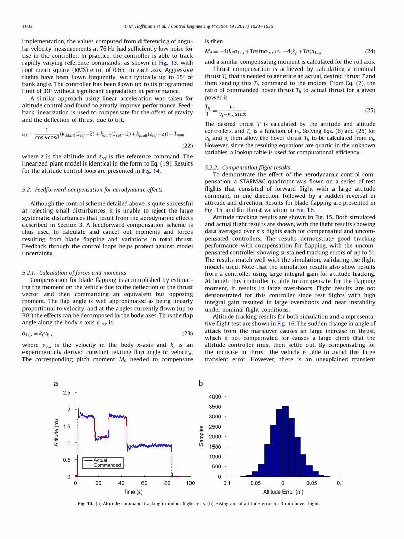
where z is the altitude and zref is the reference command. Thelinearized plant model is identical in the form to Eq. (19). Resultsfor the altitude control loop are presented in Fig. 14.
5.2. Feedforward compensation for aerodynamic effects
Although the control scheme detailed above is quite successfulat rejecting small disturbances, it is unable to reject the largesystematic disturbances that result from the aerodynamic effectsdescribed in Section 3. A feedforward compensation scheme isthus used to calculate and cancel out moments and forcesresulting from blade flapping and variations in total thrust.Feedback through the control loops helps protect against modeluncertainty.
5.2.1. Calculation of forces and moments
Compensation for blade flapping is accomplished by estimat-ing the moment on the vehicle due to the deflection of the thrustvector, and then commanding an equivalent but opposingmoment. The flap angle is well approximated as being linearlyproportional to velocity, and at the angles currently flown (up to301) the effects can be decomposed in the body axes. Thus the flapangle along the body x-axis a1s,x is
a1s,x ¼ kf vb,x ð23Þ
where vb,x is the velocity in the body x-axis and kf is anexperimentally derived constant relating flap angle to velocity.The corresponding pitch moment My needed to compensate
0 20 40 60 80 1000
0.5
1
1.5
2
2.5
Time (s)
Alti
tude
(m)
ActualCommanded
Sam
ples
Fig. 14. (a) Altitude command tracking in indoor flight tests
is then
My ¼�4ðkba1s,xþThsina1s,xÞ ��4ðkbþThÞa1s,x ð24Þ
and a similar compensating moment is calculated for the roll axis.Thrust compensation is achieved by calculating a nominal
thrust Th that is needed to generate an actual, desired thrust T andthen sending this Th command to the motors. From Eq. (7), theratio of commanded hover thrust Th to actual thrust for a givenpower is
Th
T¼
vh
vi�v1sina ð25Þ
The desired thrust T is calculated by the attitude and altitudecontrollers, and Th is a function of vh. Solving Eqs. (6) and (25) forvh and vi then allow the hover thrust Th to be calculated from vh.However, since the resulting equations are quartic in the unknownvariables, a lookup table is used for computational efficiency.
5.2.2. Compensation flight results
To demonstrate the effect of the aerodynamic control com-pensation, a STARMAC quadrotor was flown on a series of testflights that consisted of forward flight with a large attitudecommand in one direction, followed by a sudden reversal inattitude and direction. Results for blade flapping are presented inFig. 15, and for thrust variation in Fig. 16.
Attitude tracking results are shown in Fig. 15. Both simulatedand actual flight results are shown, with the flight results showingdata averaged over six flights each for compensated and uncom-pensated controllers. The results demonstrate good trackingperformance with compensation for flapping, with the uncom-pensated controller showing sustained tracking errors of up to 51.The results match well with the simulation, validating the flightmodels used. Note that the simulation results also show resultsfrom a controller using large integral gain for attitude tracking.Although this controller is able to compensate for the flappingmoment, it results in large overshoots. Flight results are notdemonstrated for this controller since test flights with highintegral gain resulted in large overshoots and near instabilityunder nominal flight conditions.
Altitude tracking results for both simulation and a representa-tive flight test are shown in Fig. 16. The sudden change in angle ofattack from the maneuver causes an large increase in thrust,which if not compensated for causes a large climb that thealtitude controller must then settle out. By compensating forthe increase in thrust, the vehicle is able to avoid this largetransient error. However, there is an unexplained transient
−0.1 −0.05 0 0.05 0.10
500
1000
1500
2000
2500
3000
3500
4000
Altitude Error (m)
. (b) Histogram of altitude error for 3 min hover flight.

0 5 10 15 20 25 30 35 40-0.15
-0.1
-0.05
0
0.05
0.1
0.15
0.2
0.25
0.3
0.35
East (m)
Alti
tude
Err
or (m
)
Simulated Altitude Error DuringStall Turn Maneuver
CompensatedDefault
0 5 10 15 20 25 30 35
-0.6
-0.4
-0.2
0
0.2
0.4
0.6
East (m)
Alti
tude
Tra
ckin
g Er
ror (
m)
Altitude Error During StallTurn Maneuver
CompensatedDefault
Fig. 16. Comparison of altitude control with and without compensation for change in thrust due to sudden change in angle of attack: (a) in simulated flight and (b) in
actual flight.
0 2 4 6 8 10 12
-20
-15
-10
-5
0
5
10
15
20Simulated Roll Responses
Time (s)
Ang
le (d
eg)
CommandedCompensatedDefaultHigh Integral Gain
0 1 2 3 4 5 6 7 8 9
-15
-10
-5
0
5
10
15
20
Roll Step Response Comparison
Time
Ang
le (d
eg)
CommandedCompensatedDefault Controller
Fig. 15. Comparison of attitude control with and without compensating for flapping. (a) Simulated results for large steps in roll. (b) Actual flight results from a series of five
flights with each controller.
G.M. Hoffmann et al. / Control Engineering Practice 19 (2011) 1023–1036 1033
behavior that causes the vehicle to drop in altitude at the end ofthe flight, as seen in Fig. 16(b). The authors were unable toreproduce this sudden descent in simulation using the modelsdescribed in Section 3, and it is currently unclear what may becausing the effect.
5.3. Position and trajectory tracking control
Position control is accomplished using successive loop closurewith the position control loop generating reference commands forthe attitude control loop. Consider control in the eE direction. UsingEqs. (4) and (1) and a small angle approximation for sinf�f, whenc¼ 0, the transfer function is XEðsÞ=FðsÞ ¼ ðTnom=mÞð1=s2Þ. Note thatthis neglects drag, induced power, and blade flapping. For thiscontrol design, those effects are again treated as disturbance forcesthat must be rejected by the control system. Setting the controlinput to uE ¼fref , the open loop plant is the convolution of the xE
dynamics with the closed loop dynamics of f, Eq. (19), using thefeedback control law of Eq. (20),
XEðsÞ
UEðsÞ¼
CðsÞTnomIf=m
s2ðts3þs2þCðsÞIfÞð26Þ
The open loop plant for the eN direction is analogous, using y ratherthan f. When ca0, the control inputs must be rotated accordingly.
A PID controller was implemented using Eq. (26). The resultsfor indoor flight tests are presented in Fig. 17. The resulting RMSeast and north error was 0.036 m. Using C(s) rather than previousPID implementations for attitude control yielded superior closedloop position control.
Extending the position controller to track trajectories wasaccomplished by changing the relevant errors signals to along-track and cross-track error. A path, LAN �R3, is defined by asequence of N desired waypoints, xd
k and desired speeds of travelvk
d along path segment Lk connecting waypoint k to kþ1, asdepicted in Fig. 18. Let tk be the unit tangent vector in thedirection of travel along the track from xd
k to xdkþ1, and nk be
the unit normal vector to the track. Then, given the currentposition xðtÞ, the cross-track error ect, error rate _ect and along-track error rate _eat are
ect ¼ ðxdk�xðtÞÞ � nk
_ect ¼�vðtÞ � nk

−0.15 −0.1 −0.05 0 0.05 0.1 0.15
−0.1
−0.05
0
0.05
0.1
East (m)
Nor
th (m
)PositionStartEnd
−0.1 −0.05 0 0.05 0.10
1000
2000
3000
4000
5000
East Error (cm)
Sam
ples
−0.1 −0.05 0 0.05 0.10
1000
2000
3000
4000
5000
North Error (cm)
Sam
ples
Fig. 17. Autonomous indoor hover performance. (a) Position plot over 3 min of flight with 0.1 m error circle. (b) Histogram of position error in north and east directions.
xx (t)d
k xdk+1tk
nk nct
uat
Λk
Fig. 18. The quadrotor travels along path segment Lk from waypoint xdk to xd
kþ1,
applying along and cross-track control inputs to track the path.
G.M. Hoffmann et al. / Control Engineering Practice 19 (2011) 1023–10361034
_eat ¼ vdk�vðtÞ � tk ð27Þ
Note that only the along-track error rate is considered, anddepends only on the velocity of the vehicle. This is done so thatthe resulting controller does not attempt to catch up or slowdown for scheduled waypoints, but simply proceeds along thetrack matching the desired velocity as closely as possible. Thisdesign choice assumes that the desired speed is selected, and thetime of achieving a waypoint is unimportant. It is straightforwardto extend the following control law by including feedback onalong-track position, if timing is important.
The trajectory tracking controller was implemented by closingthe loop on along-track rate error and cross-track error. This isessentially piecewise PI control in velocity in the along-trackdirection, and PID control in the cross-track direction,
uat ¼ Kd,at _eatþKi,at
Z t
0
_eat dt
uct ¼ Kp,ctectþKd,ct _ectþKi,ct
Z t
0
_ect dt ð28Þ
where control inputs uat and uct are the attitude commands forvehicle tilt in the along-track and cross-track directions, respec-tively. They are rotated by c and by the trajectory orientation togenerate fref and yref commands for the inner loop. Transition fromsegment k to kþ1 occurs when the vehicle crosses the line segment
normal to the path at the end of the segment. Upon completion ofLi, the integrators are reset. The trajectory controller presented hereis intended for use with a coarse set of waypoints, focusing onaccurate line tracking. It has been improved upon for finer resolu-tion paths by computing feedforward inputs to follow a least-normcontrol input solution through the waypoints, though the details areout of the scope of this paper.
The controller defined in Eq. (28) was implemented on theSTARMAC platform in both indoor and outdoor settings, withresults presented in Fig. 19. The indoor results demonstratetracking errors of under 70.1 m throughout the box shapedtrajectory, and show the largest overshoot when switching fromone track to the next, as the desired direction of travel suddenlyswitches by 901. For the outdoor flight tests, the gains on thecross-track and along-track controllers were reduced signifi-cantly, and the resulting errors increased to 70.5 m. Lower gainswere used due to increased oscillations when in hover conditionoutside, and may be attributed to either significant wind gustdisturbances or to the decreased position update rate from 15 Hzfor the indoor positioning system to 10 Hz for the carrier phasedifferential GPS solution.
This trajectory controller has some interesting properties. Sincethe path is composed only of line segments, overshoot on sharpcorners is inevitable, a systematic tracking error. This is addressed bythe alternative option using least-norm feedforward inputs, asdescribed above. Another property arises due to the lack of mandatedtimes to be at each waypoint. The trajectory tracking controller doesnot deviate from the intended path to try to meet a deadline—arequired feature when the path is meant to avoid obstacles.
5.4. Applications
The precise, accurate control enabled by the controllers describedabove have allowed STARMAC to become a useful and flexible

−0.6 −0.4 −0.2 0 0.2 0.4 0.6
−0.6
−0.4
−0.2
0
0.2
0.4
East (m)
Nor
th (m
)
−4 −2 0 2 40
2
4
6
8
10
East (m)
Nor
th (m
)
Fig. 19. Tracking a trajectory (a) indoors, at 0.5 m/s, with an error of under 0.1 m, and (b) outdoors, at 2.0 m/s, with an error of under 0.5 m.
Fig. 20. Experimental flight tests conducted using the STARMAC platform and controllers discussed in this paper showing (a) decentralized cooperative collision avoidance
using Nash bargaining; flight experiment and iterative solutions, (b) obstacle avoidance using the Tunnel-MILP algorithm; flight experiment and computed path through
the tunnel decomposition, and (c) information-theoretic cooperative search; quadrotors carrying beacon receivers and mutual information contours for one vehicle. (For
interpretation of the references to color in this figure legend, the reader is referred to the web version of this article.)
G.M. Hoffmann et al. / Control Engineering Practice 19 (2011) 1023–1036 1035
research platform. Although the details of these applications areoutside the scope of this paper, a brief discussion of several flightexperiments will be presented to highlight the utility of theSTARMAC quadrotors in developing and demonstrating multi-vehi-cle control algorithms.
Decentralized multi-vehicle collision avoidance is a veryimportant issue for multi-vehicle systems. STARMAC was usedto demonstrate a decentralized algorithm designed to generateoptimal, collision-free trajectories using Nash Bargaining(Waslander & Tomlin, 2010). For the flight test, three STARMACquadrotors were placed such that their desired trajectories wouldresult in violating a minimum separation distance. The quadro-tors communicated with each other to generate safe trajectoriesusing only their on-board computation, and successfully flewthese trajectories (see Fig. 20a).
Another important task for UAVs is performing obstacleavoidance in tight areas. For this particular experiment, a mini-mum-time, optimal trajectory was generated from an obstaclemap using the Tunnel-MILP algorithm (Vitus et al., 2008, 2010).This trajectory was generated off-board and transmitted to aSTARMAC quadrotor, which then successfully bypassed the obsta-cles placed in the field. Fig. 20b shows both the obstacle field andthe desired and actual trajectories of the STARMAC quadrotor.
Finally, another experiment was conducted using a pair ofSTARMAC quadrotors to cooperatively locate a magnetic avalancherescue beacon (Hoffmann, 2008). The STARMAC quadrotors usedon-board avalanche rescue sensors to update particle filter repre-sentations of the location of an unknown beacon (blue dots inFig. 20c) and used an information-theoretic approach to generatetrajectories that maximized information gain (Hoffmann et al.,

G.M. Hoffmann et al. / Control Engineering Practice 19 (2011) 1023–10361036
2006a; Hoffmann & Tomlin, 2010). All optimization and control wasperformed using the on-board PC104 computers.
6. Conclusion
This work describes in detail the vehicle dynamics, vehicle design,and control system design of the STARMAC quadrotor testbed. Withthe successful completion of autonomous trajectory tracking flightdemonstrations on the quadrotor helicopters of the STARMACplatform, a major milestone has been achieved not only for thetestbed but also for the development of quadrotors as viableautonomous micro-aerial vehicles. The many lessons learned in theprocess of developing these vehicles should be of significant utility toany other groups interested in accessible, trouble-free UAVdevelopment.
Many exciting avenues of future investigations are nowpossible. For example, the incorporation of the aerodynamiceffects outlined in Section 3 into the trajectory tracking controllaw will allow for more precise tracking and therefore enable highspeed operation in cluttered environments. Similarly, the expan-sion of multi-vehicle capabilities is now a priority, as is theincorporation of additional sensors to enable on-board estimationof and operation in unknown environments. With STARMAC, areliable, capable and convenient testbed of autonomous aerialvehicles, the multi-vehicle applications for which it wasdeveloped are now clearly within reach.
Acknowledgments
The authors would like to thank Jung Soon Jang, David Shoe-maker, David Dostal, Dev Gorur Rajnarayan, Vijay Pradeep, PaulYu, Justin Hendrickson, and Michael Vitus, for their many con-tributions to the development of the STARMAC testbed. We wouldalso like to thank Mark Woodward for the image processingprogram used for the USB camera system.
References
Achtelik, M., Bachrach, A., He, R., Prentice, S., & Roy, N. (2009). Autonomous navigationand exploration of a quadrotor helicopter in GPS-denied indoor environments. InAUVSI first symposium on indoor flight issues, Mayaguez, Puerto Rico.
Advanced Digital Logic (2008). ADL855 PC104þ . /http://www.adlogic-pc104.com/products/cpu/pc104/datasheets/MSM855.pdfS.
Aeryon Labs Inc., Aeryon Scout (2009). /www.aeryon.comS.Altug, E., Ostrowski, J. P., & Taylor, C. J. (2003). Quadrotor control using dual
camera visual feedback. In Proceedings of the IEEE international conference onrobotics and automation (pp. 4294–4299), Taipei, Taiwan.
Ascending Technologies GmbH, AscTec hummingbird (2008). /http://www.asctec.deS.BackCountry Access (2008). Tracker DTS Digital Avalanche Beacon. /http://www.
bcaccess.com/bca_products/tracker/index.phpS.Bouabdallah, S., Murrieri, P., & Siegwart, R. (2005). Towards autonomous indoor
micro VTOL. Autonomous Robots, 18, 171–183.Computers, G. E. (2008). Robostix and Verdex Boards. /http://www.gumstix.com/S.Courbon, J., Mezouar, Y., Guenard, N., & Martinet, P. (2010). Vision-based naviga-
tion of unmanned aerial vehicles. Control Engineering Practice, 18, 789–799.Craciunas, S., Kirsch, C., Rock, H., & Trummer, R. (2008). The javiator: A high-
payload quadrotor UAV with high-level programming capabilities. In Proceed-ings of the GNC. AIAA.
DraganFly-Innovations, DraganFlyer V (2008). /http://www.rctoys.comS.DraganFly-Innovations, DraganFlyer X4 (2009). /http://www.rctoys.comS.Escareno, J., Salazar-Cruz, S., & Lozano, R. (2006). Embedded control of a four-rotor
uav. In Proceedings of the AACC American control conference (pp. 3936–3941),Minneapolis, MN.
Gillula, J., Huang, H., Vitus, M. P., & Tomlin, C. J. (2010). Design of guaranteed safemaneuvers using reachable sets: Autonomous quadrotor aerobatics in theoryand practice. In The proceedings of the 2010 IEEE international conference onrobotics and automation, Anchorage, Alaska.
Guenard, N., Hamel, T., & Moreau, V. (2005). Dynamic modeling and intuitivecontrol strategy for an x4-flyer. In Proceedings of the IEEE inter-national conference on robotics and automation (pp. 141–146), Budapest,Hungary.
Hoffmann, G., Rajnarayan, D. G., Waslander, S. L., Dostal, D., Jang, J. S., & Tomlin, C.J. (2004). The Stanford testbed of autonomous rotorcraft for multi agentcontrol (STARMAC). In Proceedings of the 23rd digital avionics systemsconference (pp. 12.E.4/1–10), Salt Lake City, UT.
Hoffmann, G. M. (2008). Autonomy for sensor-rich vehicles: Interaction betweensensing and control actions. Ph.D. thesis, Stanford University.
Hoffmann, G. M., Huang, H., Waslander, S. L., & Tomlin, C. J. (2007).Quadrotor helicopter flight dynamics and control: Theory and experiment.In Proceedings of the AIAA guidance, navigation, and control conference, HiltonHead, SC.
Hoffmann, G. M., & Tomlin, C. J. (2010). Mobile sensor network control usingmutual information methods and particle filters. IEEE Transactions on Auto-matic Control, 55, 32–47.
Hoffmann, G. M., Waslander, S. L., & Tomlin, C. J. (2006a). Mutual informationmethods with particle filters for mobile sensor network control. In Proceedingsof the 45th IEEE conference decision and control (pp. 1019–1024), San Diego, CA.
Hoffmann, G. M., Waslander, S. L., & Tomlin, C. J. (2006b). Distributed cooperativesearch using information-theoretic costs for particle filters with quadrotorapplications. In Proceedings of the AIAA guidance, navigation, and controlconference, Keystone, CO.
Hokuyo (2008). URG-04LX Laser Range Finder. /http://www.hokuyo-aut.jp/products/urg/urg.htmS.
Huang, H., Hoffmann, G. M., Waslander, S. L., & Tomlin, C. (2009). Aerodynamicsand control of autonomous quadrotor helicopters in aggressive maneuvering.In Proceedings of the IEEE international conference on robotics and automation(pp. 3277–3282), Kobe, Japan.
Hull, L. (2010). Drone makes first UK ‘arrest’ as police catch car thief hiding underbushes. Daily Mail Online, 2010. /http://www.dailymail.co.uk/news/article-1250177/Police-make-arrest-using-unmanned-drone.htmlS.
Johnson, W. (1980). Helicopter theory. Princeton, NJ: Princeton University Presspp.126–131.
Leishman, J. G. (2000). Principles of helicopter aerodynamics. New York, NY:Cambridge University Presspp. 36–71.
Lupashin, S., Schollig, A., Sherback, M., & D’Andrea, R. (2010). A simple learningstrategy for high-speed quadrocopter multi-flips.
Michael, N., Fink, J., & Kumar, V. (2009). Cooperative manipulation and transporta-tion with aerial robots. In Robotics: Science and Systems, Seattle, WA.
Microdrones GmbH, MD4-200 quadrotor helicopter (2008). /http://www.microdrones.com/news_waypoint_navigation.htmlS.
Newman, S. (1994). The foundations of helicopter flight. New York, NY: HalstedPress (pp. 107–116).
Nice, E. B. (2004). Design of a four rotor hovering vehicle. Master’s thesis, CornellUniversity, 2004.
Park, S., et al. (2005). Ric (robust internal-loop compensator) based flight control ofa quad-rotor type uav. In IEEE/RSJ international conference on intelligent roboticsand systems, Edmonton, Alberta.
Pounds, P., Mahony, R., & Corke, P. (2006). Modelling and control of a quad-rotorrobot. In Proceedings of the Australasian conference on robotics and automation,Auckland, New Zealand.
Pounds, P., Mahony, R., & Corke, P. (2010). Modelling and control of a largequadrotor robot. Control Engineering Practice, 18, 691–699.
Pounds, P., Mahony, R., Gresham, J., Corke, P., & Roberts, J. (2004). Towardsdynamically-favourable quad-rotor aerial robots. In Proceedings of the Austra-lasian conference on robotics and automation, Canberra, Australia.
Prouty, R. W. (1990). Helicopter performance, stability, and control. Malabar,FL: Krieger Publishing Companypp. 143–146, 476–477.
Valenti, M., Bethke, B., Fiore, G., How, J. P., & Feron, E. (2006). Indoor multi-vehicleflight testbed for fault detection, isolation, and recovery. In Proceedings of theAIAA guidance, navigation, and control conference, Keystone, CO.
Videre Design (2008). STH-MDCS 2 Stereo Vision Head. /http://www.videredesign.com/sthmdcs2.htmS.
Vitus, M., Pradeep, V., Hoffmann, G. M., Waslander, S. L., & Tomlin, C. J. (2008).Tunnel-MILP: Path planning with sequential convex polytopes. In AIAAguidance, navigation and control conference and exhibit, Honolulu, Hawaii, USA.
Vitus, M. P., Waslander, S. L., & Tomlin, C. J. (2010). IEEE Journal of Robotics,submitted for publication.
Waslander, S. L., Hoffmann, G. M., Jang, J. S., & Tomlin, C. J. (2005). Multi-agentquadrotor testbed control design: Integral sliding mode vs. reinforcementlearning. In IEEE/RSJ international conference on intelligent robotics and systems(pp. 468–473), Edmonton, Alberta.
Waslander, S. L., Inalhan, G., & Tomlin, C. J. (2004). Decentralized optimization viaNash bargaining. In D. Grundel, R. Murphey, & P. M. Pardalos (Eds.), Theory andalgorithms for cooperative systems, Vol. 4 (pp. 565–585). World ScientificPublishing Co.
Waslander, S. L. & Tomlin, C. J. (2010). Decentralized optimization and the Nashbargaining solution for autonomous collision avoidance. IEEE Transactions onControl Systems Technology, submitted for publication.


![Evolution of flight in animals · 2 Evolution of insect flight Several theories have been suggested for the origin of flight in insects (summarized in Thomas and Norberg [1]).](https://static.fdocuments.us/doc/165x107/5f0850067e708231d4216393/evolution-of-iight-in-animals-2-evolution-of-insect-iight-several-theories-have.jpg)