Control and Sensing Platform of Magnetically driven ...
6
Control and Sensing Platform of Magnetically driven Microtool for On-Chip Single Cell Evaluation Tomohiro Kawahara*, Masaya Hagiwara*, Yoko Yamanishi**, and Fumihito Arai* * Graduate School of Engineering, Nagoya University, Furo-cho, Chikusa-ku, Nagoya 464-8603, Japan ** PRESTO, Japan Science and Technology Agency, 4-1-8, Honcho, Kawaguchi-shi, Saitama 332-0012, Japan Abstract: In this paper, we discuss a development of control and sensing platform for an on-chip single cell evaluation by magnetically driven microtool (MMT). The design and fabrication of the MMT is shown. Through the basic experiments, the advantage of the proposed platform, the performance of the position control (positioning accuracy: 30 m), and the force sensing (sensing accuracy: 100 N) of the MMT are confirmed. 1. INTRODUCTION In the biomedical field especially cloning procedure, an oocyte with the diameter of 100-150 m is handled in a petri dish by using human operated micromanipulators with microtools, as shown in Figure 1. However, this approach has a couple of issues; skill dependent procedure, low time efficiency, and contamination. In order to solve these problems, we have proposed an automatic oocyte actuation by microrobot called Magnetically Driven Microtool (MMT) in a microfluidic chip, as shown in Figure 2 [1]-[3]. In this approach, the MMT placed in the microchannel is driven by a magnet without contact and the microchip made by PDMS (polydimethylsiloxane) is disposable. In the conventional work, the positioning of the MMT was achieved by manual operation of the permanent magnet with the low positioning accuracy. In this paper, we discuss the vision based feedback control to improve the positioning accuracy of the MMT. By using this system, we also discuss the on-chip force sensing by MMT to evaluate the mechanical property of single cell. 2. FEEDBACK POSITION CONTROL OF MMT In the conventional work, several microtools have been proposed without sensor feedback position control [4]-[8]. Figure 3 shows the newly developed control system comprising a linear stage for magnet actuation, a microscope with a CCD camera, a PC for controlling the stage and capturing image data from the CCD camera, and a microfluidic chip with a MMT. The stage is controlled with the accuracy of 1 m by commands from the PC to a stage driver. A permanent magnet (Neodymium, 3 mm x 5 mm) is attached on the tip of the stage. The images from the CCD camera are fed into the computer through an image capture card (480 x 640 pixels) and processed for detecting the Figure 1: Human operated oocyte manipulation. Figure 2: Conceptual image of oocyte manipulation by Magnetically driven Microtool (MMT). of the MMT with the sampling rate of 30 Hz. For the position control of the MMT, we also developed the software which can interactively change the experimental parameters (magnet position, magnet speed, image processing), as shown in Figure 4. From these configurations, the controllable rate of experimental system is configured at 30 Hz. Figure 5 shows the process flow of the fabrication of the Ni type MMT ( 1 mm x 0.5 mm).
Transcript of Control and Sensing Platform of Magnetically driven ...

Control and Sensing Platform of Magnetically driven Microtool for On-Chip Single Cell Evaluation
Tomohiro Kawahara*, Masaya Hagiwara*, Yoko Yamanishi**, and Fumihito Arai*
* Graduate School of Engineering, Nagoya University, Furo-cho, Chikusa-ku, Nagoya 464-8603, Japan ** PRESTO, Japan Science and Technology Agency, 4-1-8, Honcho, Kawaguchi-shi, Saitama 332-0012, Japan
Abstract: In this paper, we discuss a development of control and sensing platform for an on-chip single cell evaluation by magnetically driven microtool (MMT). The design and fabrication of the MMT is shown. Through the basic experiments, the advantage of the proposed platform, the performance of the position control (positioning accuracy: 30 �m), and the force sensing (sensing accuracy: 100 �N) of the MMT are confirmed.
1. INTRODUCTION
In the biomedical field especially cloning procedure, an oocyte with the diameter of 100-150 �m is handled in a petri dish by using human operated micromanipulators with microtools, as shown in Figure 1. However, this approach has a couple of issues; skill dependent procedure, low time efficiency, and contamination. In order to solve these problems, we have proposed an automatic oocyte actuation by microrobot called Magnetically Driven Microtool (MMT) in a microfluidic chip, as shown in Figure 2 [1]-[3]. In this approach, the MMT placed in the microchannel is driven by a magnet without contact and the microchip made by PDMS (polydimethylsiloxane) is disposable. In the conventional work, the positioning of the MMT was achieved by manual operation of the permanent magnet with the low positioning accuracy. In this paper, we discuss the vision based feedback control to improve the positioning accuracy of the MMT. By using this system, we also discuss the on-chip force sensing by MMT to evaluate the mechanical property of single cell.
2. FEEDBACK POSITION CONTROL OF MMT
In the conventional work, several microtools have been proposed without sensor feedback position control [4]-[8]. Figure 3 shows the newly developed control system comprising a linear stage for magnet actuation, a microscope with a CCD camera, a PC for controlling the stage and capturing image data from the CCD camera, and a microfluidic chip with a MMT. The stage is controlled with the accuracy of 1 �m by commands from the PC to a stage driver. A permanent magnet (Neodymium, � 3 mm x 5 mm) is attached on the tip of the stage. The images from the CCD camera are fed into the computer through an image capture card (480 x 640 pixels) and processed for detecting the
Figure 1: Human operated oocyte manipulation.
Figure 2: Conceptual image of oocyte manipulation by Magnetically driven Microtool (MMT).
of the MMT with the sampling rate of 30 Hz. For the position control of the MMT, we also developed the software which can interactively change the experimental parameters (magnet position, magnet speed, image processing), as shown in Figure 4. From these configurations, the controllable rate of experimental system is configured at 30 Hz. Figure 5 shows the process flow of the fabrication of the Ni type MMT (� 1 mm x 0.5 mm).

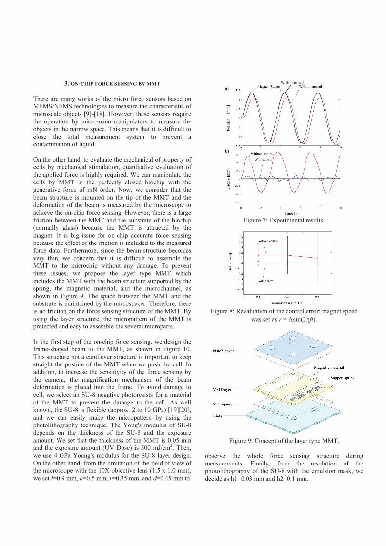
Figure 6 shows the block diagram of the position control for the MMT. By estimation the center of gravity of the MMT from the captured image data, we can achieve a feedback control of the MMT. However, magnet based precise control is difficult by well known as a stick slip effect which generates an uncontrollable area. To reducing this effect, we design an observer by estimating the stick slip effect as an input disturbance. By both the PI controller and the disturbance observer, the precise position control of the MMT is achieved. Designed system and observer are follows: [3rd order system with disturbance] [Disturbance observer] where, yMMT=x1, x2, d ,and ^ show the position of MMT estimated from the center of gravity of MMT, the velocity of MMT, the disturbance from the stick-slip effect, and the estimated value, respectively. The gain of the overseer was decided by using the pole placement method. Figure 7(a) shows the experimental results where the black line shows the magnet position, the red line shows the MMT position without control, and the blue line shows the MMT position with control, respectively. Figure 7(b) shows the positioning error. From the result of without control, we can see that the large positioning error by stick-slip effect exits with the 500 �m order. On the other hand, from the result of with vision based feedback control, we confirmed that the positioning accuracy is improved to the less than 100 �m. Figure 8 shows the mean error and the standard deviation of MMT when we changed the velocity of magnet. From this result, we can see that the mean error with control is less than 30 �m in any speed.
Figure 3: Developed system for MMT position control. Figure 4: Developed interactive software for MMT control.
Figure 5: Process flow for the Ni type MMT.
Figure 6: Designed controller with disturbance observer.
3. ON-CHIP FORCE SENSING BY MMT There are many works of the micro force sensors based on MEMS/NEMS technologies to measure the characteristic of microscale objects [9]-[18]. However, these sensors require the operation by micro-nano-manipulators to measure the objects in the narrow space. This means that it is difficult to close the total measurement system to prevent a contamination of liquid. On the other hand, to evaluate the mechanical of property of cells by mechanical stimulation, quantitative evaluation of the applied force is highly required. We can manipulate the cells by MMT in the perfectly closed biochip with the generative force of mN order. Now, we consider that the beam structure is mounted on the tip of the MMT and the deformation of the beam is measured by the microscope to achieve the on-chip force sensing. However, there is a large friction between the MMT and the substrate of the biochip (normally glass) because the MMT is attracted by the magnet. It is big issue for on-chip accurate force sensing because the effect of the friction is included to the measured force data. Furthermore, since the beam structure becomes very thin, we concern that it is difficult to assemble the MMT to the microchip without any damage. To prevent these issues, we propose the layer type MMT which includes the MMT with the beam structure supported by the spring, the magnetic material, and the microchannel, as shown in Figure 9. The space between the MMT and the substrate is maintained by the microspacer. Therefore, there is no friction on the force sensing structure of the MMT. By using the layer structure, the micropattern of the MMT is protected and easy to assemble the several microparts. In the first step of the on-chip force sensing, we design the frame-shaped beam to the MMT, as shown in Figure 10. This structure not a cantilever structure is important to keep straight the posture of the MMT when we push the cell. In addition, to increase the sensitivity of the force sensing by the camera, the magnification mechanism of the beam deformation is placed into the frame. To avoid damage to cell, we select an SU-8 negative photoresists for a material of the MMT to prevent the damage to the cell. As well known, the SU-8 is flexible (approx. 2 to 10 GPa) [19][20], and we can easily make the micropattern by using the photolithography technique. The Yong's modulus of SU-8 depends on the thickness of the SU-8 and the exposure amount. We set that the thickness of the MMT is 0.05 mm and the exposure amount (UV Dose) is 500 mJ/cm2. Then, we use 4 GPa Young's modulus for the SU-8 layer design. On the other hand, from the limitation of the field of view of the microscope with the 10X objective lens (1.5 x 1.0 mm), we set l=0.9 mm, h=0.5 mm, r=0.35 mm, and d=0.45 mm to
Figure 7: Experimental results.
Figure 8: Revaluation of the control error; magnet speed was set as r = Asin(2�ft).
Figure 9: Concept of the layer type MMT.
observe the whole force sensing structure during measurements. Finally, from the resolution of the photolithography of the SU-8 with the emulsion mask, we decide as h1=0.03 mm and h2=0.1 mm.
With control
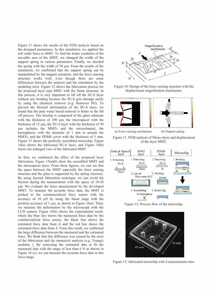
Figure 11 shows the results of the FEM analysis based on the designed parameters. In this simulation, we applied the mN order force to MMT. To find the better condition of the movable area of the MMT, we changed the width of the support spring in various parameters. Finally, we decided the spring with the width of 50 �m. From the results of the simulation, we confirmed that the support spring can be manipulated by the magnet actuation, and the force sensing structure works well, even though there are some differences between the analysis and the simulation by the modeling error. Figure 12 shows the fabrication process for the proposed layer type MMT with the flame structure. In this process, it is very important to lift off the SU-8 layer without any bending because the SU-8 gets damage easily by using the chemical remover (e.g. Remover PG). To prevent the flexural deformation of the SU-8 layer, we found that the pure water based removal is better to the lift off process. The biochip is composed of the glass substrate with the thickness of 100 �m, the microspacer with the thickness of 15 �m, the SU-8 layer with the thickness of 50 �m includes the MMTs and the microchannel, the hemispheres with the diameter of 1 mm to actuate the MMTs, and the PDMS cover with the thickness of 5 mm. Figure 13 shows the perfectly assembled microchip. Figure 14(a) shows the fabricated SU-8 layer, and Figure 14(b) shows the enlarged view of the fabricated MMT. At first, we confirmed the effect of the proposed layer fabrication. Figure 15(a)(b) show the assembled MMT and the microspacer layer. From these figures, we can see that the space between the MMT especially the force sensing structure and the glass is supported by the spring structure. By using layered fabrication technique, we can avoid the friction during the measurement with the space of 10-20 �m. We evaluate the force measurement by the developed MMT. To measure the accurate force data, the MMT is pushed to the commercialized force sensor with the accuracy of 10 �N by using the linear stage with the position accuracy of 1 �m, as shown in Figure 16(a). Then, we measure the deformation by the microscope with the CCD camera. Figure 16(b) shows the experimental result, where the blue line shows the measured force data by the commercialized force sensor, the black line shows the estimated force data from �, and the red line shows the estimated force data from X. From this result, we confirmed the large difference between the measured and the estimated force. We think that this difference was caused by the error of the fabrication and the numerical analysis (e.g. Young's modulus ). By correcting the estimated data to fit the measured data with the range of less than 6 N as shown in Figure 16 (c), we can measure the accurate force data in this force range.
Figure 10: Design of the force sensing structure with the displacement magnification mechanism.
(a) Force sensing mechanism (b) Support spring
Figure 11: FEM analysis of Mises stress and displacement of the layer MMT.
Figure 12: Process flow of the microchip.
Figure 13: fabricated microchip with 4 measurement sites.

Figure 14: Fabricated MMT layer.
Figure 15: Assembled the MMT layer (without Fe hemisphere) and the microspacer layer.
Figure 16: Force calibration of the sensing structure.
4. CONCLUSION In this paper, we discussed a control and sensing platform of magnetically driven microtool (MMT) for an on-chip single cell evaluation. The main results obtained through the work are as follows: 1. We achieved the precise position control of the MMT with the positioning accuracy of 30 �m in microfluidic chip. The designed vision based controller is composed of the PI controller with the disturbance observer. In the future work, we will expand the proposed control method to multiple MMT control for cell (e.g. swine oocyte) rotating/cutting application. 2. We also achieved an on-chip force sensing by MMT with the frame based force sensing structure includes the displacement magnification mechanism. The microchip is composed of a microspaceer, an MMT layer, an Fe hemisphere and a PDMS cover. These parts are assembled by layer fabrication technique. It is confirmed that the fore measurement accuracy of the MMT is 100 �N in the developed microchip. 3. Through our basic experiments, we have confirmed the effectiveness of the fabrication method and the performance of the developed platform. We think that the developed platform is useful for evaluation of living cells in the biochip. The combination of the MMT and disposable PDMS bio-chip, and the camera based measurement achieves very low cost control/measurement system.
ACKNOWLEDGEMENT This work has been supported by the Ministry of Education, Culture, Sports, Science and Technology Great-in-Aid for Scientific Research (22860030) and the Nagoya University Global COE Program, ``COE for Education and Research of Micro-Nano Mechatronics," .

REFERENCES
[1] Y. Yamanishi, S. Sakuma, and F. Arai, ``On-chip cell manipulation by magnetically modified soft microactuators,'' Proc of the IEEE Int Conf on Robotics and Automation, pp. 899-904, 2008. [2] Y. Yamanishi, S. Sakuma, K. Onda, and F. Arai, ``Powerful actuation of magnetized microtools by focused magnetic field for particle sorting in a chip,'' Biomed Microdevices, vol. 10, pp. 411-419, 2008. [3] M. Hagiwara, T. Kawahara, Y. Yamanishi, and F. Arai, ``Driving method of microtool by horizontally arranged permanent magnets for single cell manipulation,'' Applied Physics Letters, vol. 97, no. 013701, pp. 1-3, 2010. [4] M. Barbic, J. J. Mock, A. P. Gray, and S. Schults, “Electromagnetic micromotor for microfluidics applications”, Applied Physics Letters, vol. 79, no. 9, pp. 1399-1402, 2001. [5] G. A. Mensing, T. M. Pearce, M. D. Graham, and D. J. Beebe, “An externally driven magnetic microstirrer”, Phil Trans R Soc London, Ser.A, vol. 362, pp. 1059-1068, 2004. [6] J. Atencia and D. J. Beebe, “Magnetically-driven biomimetic micro pumping using vortices”. Lab on a Chip, vol. 4, pp. 598-602, 2004. [7] M. Roper, R. Dreyfus, J. Baudry, M. Fermigier, J. Bibette, and H. A. Stone, “On the dynamics of magnetically driven elastic filaments”, J of Fluid Mechanics, vol. 554, pp. 167-190, 2006. [8] L. Gao, N. J. Gottron, L. N. Virgin and B. B. Yellen, “The synchronization of superparamagnetic beads driven by a micro-magnetic ratchet”, Lab on a Chip, vol. 10, pp. 2108-2114, 2010. [9] M.E. Fauver, D.L. Dunaway, D.H. Lilienfeld, H.G.Craighead, and G.H. Pollack, ``Microfabricated cantilevers for measurement of subcellular and molecular forces,'' IEEE Trans on Biomedical Engineering, vol. 45, no. 7, pp.891-898, 1998. [10] Y. Sun, B.J. Nelson, D.P. Potasek, and E. Enikov, ``A bulkmicrofabricated multi-axis capacitive cellular force sensor using transverse comb drives,'' J Micromech Microeng, vol. 12, pp. 832-840, 2002. [11] Y. Sun, K.T. Wan, K.P. Roberts, J.C. Bischof, and B.J. Nelson, ``Mechanical property characterization of mouse zona pellucida,'' IEEE Trans on Nanobioscience, vol. 2, no. 4, pp. 279-286, 2003. [12] K.H. Jeong, C. Keller, and L. Lee, ``Direct force measurements of biomolecular interactions by nanomechanical force gauge,'' Applied Physics Letters, vol. 86, no. 193901, pp. 1-3, 2005. [13] S. Koch, G. Thayer, A. Corwin, and M. de Boer, ``Micromachined piconewton force sensor for biophysics investigations,'' Applied Physics Letters, vol. 89, no. 173901, pp. 1-3, 2006.
[14] B. Wacogne, C. Pieralli, C. Roux, and T. Gharbi, ``Measuring the mechanical behaviour of human oocytes with a very simple SU-8 micro-tool,'' Biomed Microdevices, vol. 10, pp. 411-419, 2008. [15] M. Nakajima, M.R. Ahmad, S. Kojima, M. Homma, and T. Fukuda, ``Local stiffness measurements of {¥it C. elegans} by buckling nanoprobes inside an environmental SEM,'' Proc of the IEEE/RSJ Int Conf on Intelligent Robots and Systems, pp. 4695-4700, 2009. [16] D.J. Cappelleri, G. Piazza, and V. Kumar, ``Two-dimensional, vision-based �N force sensor for microrobotics,'' Proc of the IEEE Int Conf on Robotics and Automation, pp. 1016-1021, 2009. [17] K. Ikuta, F. Sato, K. Kadoguchi, and S. Itoh, ``Optical driven master-slave controllable nano-manipulator with real-time force sensing,'' Proc of the IEEE Int Conf on Micro Electro Mechanical Systems, pp. 539-5421, 2008. [18] M. Papi, L. Sylla, T. Parasassi, R. Brunelli, M. Monaci, G. Maulucci, M. Missori, G. Arcovito, F. Ursini, and M.D. Spirito, ``Evidence of elastic to plastic transition in the zona pellucida of oocytes using atomic force spectroscopy,'' Applied Physics Letters, vol. 94, no. 153902, pp. 1-3, 2009. [19] H.S. Khoo, K.K. Liu, and F.G. T, ``Mechanical strength and interfacial failure analysis of cantilevered SU-8 microposts,'' J Micromech Microeng, vol. 13, pp. 822-831, 2003. [20] D. Bachmann, B. Schoberle, S. Kuhne, Y. Leiner, and C. Hierold, ``Fabrication and characterization of folded SU-8 suspensions for MEMS applications,'' Sensors and Actuators A, vol. 130-131, pp. 379-386, 2006.