Contribution to Software Development Method … based on Generalized Requirement Approach ... Figure...
114
i Metropolitan University Faculty of Information Technology Contribution to Software Development Method based on Generalized Requirement Approach DISSERTATION submitted in partial satisfaction of the requirements for the degree of DOCTOR OF SCIENCE in Software Engineering Thesis supervisor PhD Candidate Radoslav Stojic Aleksandar Bulajic Beograd, 2014 © Aleksandar Bulajic, 2014. All rights reserved.
-
Upload
truongtram -
Category
Documents
-
view
213 -
download
0
Transcript of Contribution to Software Development Method … based on Generalized Requirement Approach ... Figure...

i
Metropolitan University
Faculty of Information Technology
Contribution to Software Development Method based on Generalized
Requirement Approach
DISSERTATION
submitted in partial satisfaction of the requirements for the degree of
DOCTOR OF SCIENCE
in Software Engineering
Thesis supervisor PhD Candidate
Radoslav Stojic Aleksandar Bulajic
Beograd, 2014
© Aleksandar Bulajic, 2014.
All rights reserved.

ii
Acknowledgments
I would like first of all to thank God, who helped me to carry this burden and who rewarded me with family and a place where I can freely express my feelings and find support.
The most important people in my life are my grandchildren, Elena and Katja, who helped me to forget about the hard work and refreshed my motivation to finish this project successfully. Many thanks and all the best to both of the Bulajic princesses!
My wife, Ljiljana, deserves special thanks for all her patience and sacrifice that not just caused her social life to suffer during this study. My boys, Nikola and Boris, and my nephew, Mark Conda, deserve special thanks too, for encouragement and infinitely believing in my skills. I wish one day to read my name in the Acknowledgements of their works, dedicated to an occasion like this one. My daughter-in-law, Mila Bulajic, deserves many thanks for extending our family and keeping us all together.
Many thanks to my mother, Dragica, for not hiding her pride, (although it can sometimes be annoying), when she touts the deeds of her great-granddaughters, grandchildren, and children.
My father, Milos, unfortunately died long ago, but I am very happy to recognize that his spirit, courage, and intelligence are still living on in our children and grandchildren.
Many thanks to Samuel Sambasivam, Chair and Professor of the Department of Computer Sciences at Azusa Pacific University in California, for more than ten years of support, friendship, and fruitful collaboration.
Professor Milan Stamatovic deserves special thanks for his positive attitude and his compliments that helped me to rise up again and again.
I would like to say thanks to my mentor, Professor Radoslav Stojic, for advising me, effectively solving administrative obstacles, and for helping me finish this study program successfully.
I would like to say thanks to Professor Dragan Domazet for his sincerity, flexibility, and quick and effective solutions of any kind of situation.
I would like to say thanks to Professor Olga Timcenko, for accepting to be a member of dissertation committee.
I would like to say thanks to Professor Slobodan Jovanovic and Professor Nenad Filipovic, who helped me to complete the study program successfully.
I would like to thank the Metropolitan University who made all this possible. Last, but not least, I would like to say thanks and express my deep regards to my dear
friend and much respected adviser, Jennifer Schoonover Sadler, who accomplished the complex job of proofreading sixteen technical and philosophical articles published in computer journals and at technical conferences all over the world. Jennifer acted as my secret mentor since the beginning of this study and pointed to inconsistencies that none else saw. Jennifer, thank you very much!

iii
Abstract
Requirements’ gathering is one of the first steps in the software development process.
Gathering business requirements, when the final product requirements are dictated by a known
client, can be a difficult process. Even if the client knows their own business best, often their
idea about a new business product is obscure, and described by general terms that contribute
very much to common misunderstandings among the participants. Business requirement
verification when the requirements are gathered using text and graphics can be a slow, error-
prone, and expensive process. Misunderstandings and omitted requirements cause the need for
revisions and increase project costs and delays.
This research work proposes a new approach to the business software development process
and is focused on the client’s understanding of how the business software development process
works as well as a demonstration of the business requirement practices during requirement
negotiation process..While the current software development process validates the business
requirement at the end of the development process, this method implementation enables
business requirement validation during the requirement negotiation phase.
The process of the business requirement negotiation is guided by a set of predefined questions.
These questions are guidelines for specifying a sufficient level of requirement details for
generating executable code that is able to demonstrate each requirement. Effective
implementation of the proposed method requires employment of the GRA Framework. Besides
providing guidelines for requirement specification, the Framework shall create executables and
provide the test environment for a requirement demonstration.
This dissertation implements an example framework that is built around a central repository.
Stored within the repository is the data collected during the requirement negotiations process.
Access to the repository is managed by a Web interface that enables a collaborative and
paperless environment. The result is that the data is stored in one place and updates are
reflected to the stakeholders immediately.
The executable code is generated by the Generator, a module that provides general
programming units that are able to create source code files, databases, SQL statements,
classes and methods, navigation menus, and demo applications, all from the data stored in the
data repository. The generated software can then be used for the business requirement
demonstration. This method assumes that any further development process is built around the
requirements repository, which can provide continuous tracking of implementation changes.
Besides readily documenting, tracking, and validating the requirements, this method addresses
multiple requirement management syndromes such as the insufficient requirements description
details provision, the IKIWISI (“I’ll know it when I see it”) Syndrome, the Yes, But Syndrome
(“That is not exactly what I mean”), and the Undiscovered Ruins Syndrome (“Now that I see it, I
have another requirement to add”).”
Keywords
Generalized Requirement Approach, Requirement Management, Business Requirements,
Software Development method, Requirement Negotiation Process

iv
Table of Contents Table of Contents ............................................................................................................iv
List of Figures ..................................................................................................................vi
1 Introduction .............................................................................................................. - 1 -
2 Research Problems .................................................................................................. - 4 -
2.1 Requirement elicitation and verification issues .................................................. - 6 -
2.2 Requirement validation issues ........................................................................... - 8 -
2.3 Missing Appropriate Tools ............................................................................... - 10 -
3 Related Work ......................................................................................................... - 12 -
3.1 Sequential Software Development Method ...................................................... - 13 -
3.2 Evolutionary Software Development Method ................................................... - 13 -
3.3 Iterative and Incremental Software Development Method ............................... - 14 -
3.3.1 SCRUM ..................................................................................................... - 16 -
3.3.2 Test-Driven Development.......................................................................... - 16 -
3.4 Formal System Development methodology ..................................................... - 17 -
3.5 Unified Software Development Process .......................................................... - 18 -
3.6 Microsoft Solution Framework (MSF) .............................................................. - 19 -
3.7 Prototyping....................................................................................................... - 20 -
3.8 Application and Code Generators .................................................................... - 21 -
3.9 Requirement Management Tools ..................................................................... - 25 -
3.10 Requirement Verification ............................................................................... - 26 -
3.11 Efficiency of Existing SDM ............................................................................. - 28 -
4 Traditional Software Development Method (SDM) ................................................. - 28 -
5 Generalized Requirement Approach (GRA) ........................................................... - 29 -
6 Generalized Requirement Approach Framework (GRAF) ...................................... - 31 -
6.1 Document and Store Requirements in the Structured Text Format Described by
Customer Language .............................................................................................. - 34 -
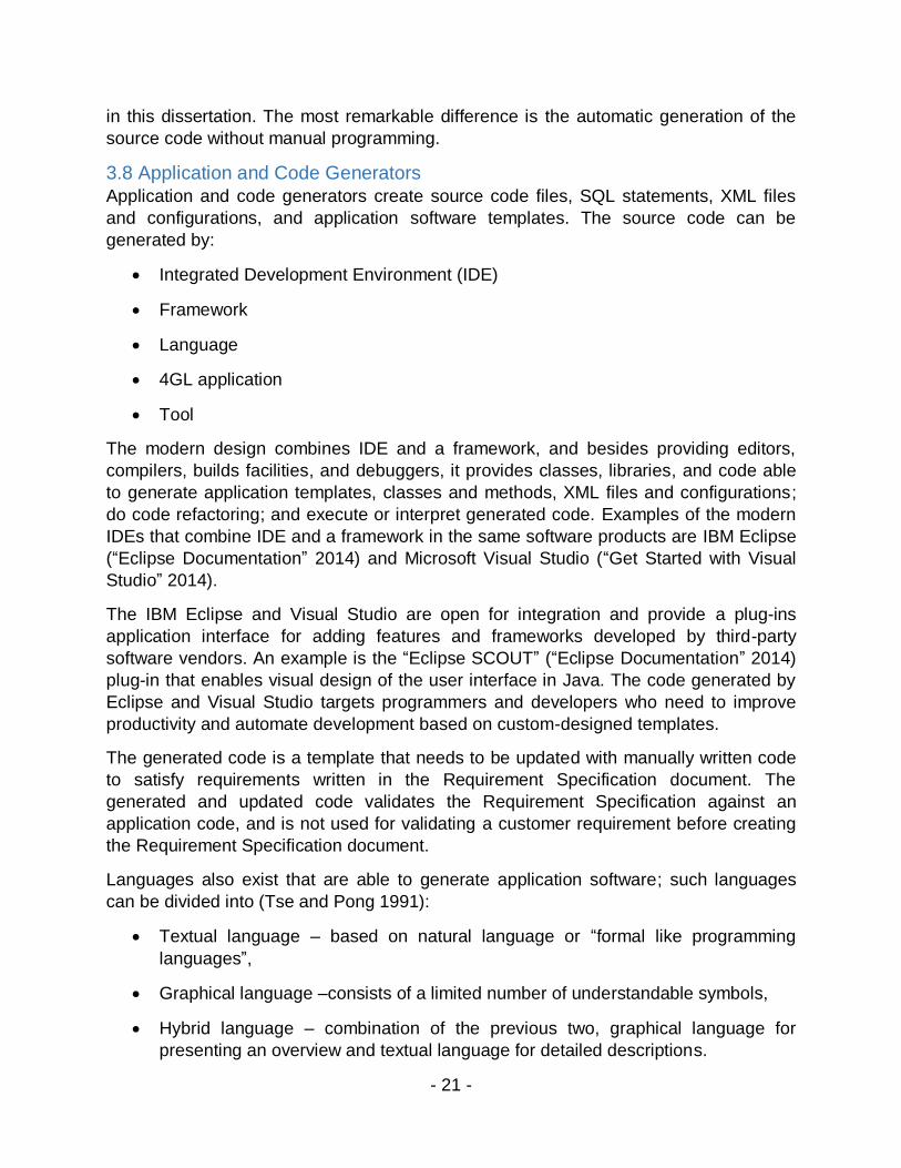
6.2 Generate Source Code without Manual Programming .................................... - 35 -
6.3 GRA Framework Generic Methods Implementation Details............................. - 37 -
6.3.1 mathFormula ............................................................................................. - 39 -
6.3.2 sqlMathExpression .................................................................................... - 41 -
6.3.3 addRowToDataSource .............................................................................. - 41 -
6.3.4 updateRowToDataSource ......................................................................... - 42 -

v
6.4 Demonstrate Working Software during the Requirement Negotiations Process- 43
-
6.5 Provide a collaborative environment ................................................................ - 43 -
7 GRA Framework Validation .................................................................................... - 44 -
7.1 Retail Store Example Application ..................................................................... - 45 -
7.2 Generating Source Code and Executables ...................................................... - 51 -
8 Summary of GRA Features and Comparison to other Approaches ........................ - 53 -
8.1 Software Development Method Generalized Requirement Approach (GRA) vs.
Agile/Prototyping.................................................................................................... - 54 -
8.2 Software Development Method Generalized Requirement Approach (GRA) vs.
Visual Modeling ..................................................................................................... - 55 -
8.3 Software Development Method Generalized Requirement Approach (GRA) vs.
Formal System Development Methodology ........................................................... - 55 -
8.4 Software Development Method Generalized Requirement Approach (GRA) vs.
Rapid Prototyping .................................................................................................. - 56 -
9 Generalized Requirement Approach Limitations .................................................... - 56 -
10 Research Contribution .......................................................................................... - 57 -
11 Conclusion ........................................................................................................... - 58 -
12 Bibliography ......................................................................................................... - 61 -
13 Appendix A – Definition of Terms ......................................................................... - 67 -
13.1 Generic Programming Unit ............................................................................ - 67 -
13.2 Generalized Requirement Approach .............................................................. - 67 -
13.3 Generalized Requirement Approach Framework ........................................... - 67 -
13.4 GRA Framework Artifacts .............................................................................. - 67 -
13.5 Generalized Requirement Approach Framework Templates and Libraries ... - 67 -
14 Appendix B – Generating Source Code ............................................................... - 68 -
15 Appendix C – Retail Store Example ..................................................................... - 71 -
16 Appendix D – Retail Store Test Documentation ................................................... - 94 -
16.1 Generated Source Code Validation ............................................................... - 94 -
16.2 Retail Store Functional Testing ...................................................................... - 96 -
16.2.1 Save Button Add Record ......................................................................... - 97 -
16.2.2 Save Button Update Record .................................................................... - 98 -
16.2.3 Delete Button .......................................................................................... - 99 -
16.2.4 Browse Buttons ..................................................................................... - 100 -

vi
16.2.5 Add To Shopping Cart Button .............................................................. - 101 -
16.2.6 Create Order ......................................................................................... - 102 -
16.2.7 Delivery Info .......................................................................................... - 103 -
16.2.8 Calculate Order Items Total .................................................................. - 104 -
16.2.9 Calculate Order Total With Handling Fee .............................................. - 105 -
16.2.10 Calculate Order Total With VAT .......................................................... - 106 -
16.2.11 Credit Card Payment ........................................................................... - 107 -
List of Figures Figure 1 V Model ................................................................................................................................ - 9 - Figure 2 Traditional Software Development Process .................................................................... - 28 - Figure 3 Generalized Requirement Approach (GRA) Overview ..................................................... - 30 - Figure 4 The GRA Framework Design Overview ............................................................................ - 32 - Figure 5 Generalized Requirement Approach Framework Source Code Generations ................. - 35 - Figure 6 Retail Store Product Purchase Process ........................................................................... - 38 - Figure 7 mathFormula ..................................................................................................................... - 40 - Figure 8 addRowToDataSource ...................................................................................................... - 42 - Figure 9 updateRowToDataSource ................................................................................................. - 43 - Figure 10 Product Components ...................................................................................................... - 46 - Figure 11 AddProductToShoppingCartUC Use Case .................................................................... - 47 - Figure 12 AddProductTC Test Case ............................................................................................... - 48 - Figure 13 AddProductTC Test Step ................................................................................................ - 49 - Figure 14 ProductForms Forms ...................................................................................................... - 50 - Figure 15 Generate Code ................................................................................................................ - 52 - Figure 16 Product Forms Generated .............................................................................................. - 52 - Table 1 Product Form Fields Description ....................................................................................... - 68 - Figure 17 The GRA Framework Implementation v1 ....................................................................... - 71 - Figure 18 The GRA Framework Front End Design ......................................................................... - 72 - Figure 19 Retail Store Project ......................................................................................................... - 73 - Figure 20 Product Component ........................................................................................................ - 74 - Figure 21 AddProductToShoppingCartUC Use Case .................................................................... - 75 - Figure 22 AddProductTC Test Case ............................................................................................... - 76 - Figure 23 AddProductTC Test Step ................................................................................................ - 77 - Figure 24 ProductForms Forms ...................................................................................................... - 78 - Figure25 Product Forms Fields ...................................................................................................... - 80 - Figure 26 Add Action addRowToDataSource ................................................................................. - 81 - Figure 27Add Action Parameter List............................................................................................... - 82 - Figure 28 ApplicationObject Component GenericMethodClass .................................................... - 83 - Figure 29 SalesOperation Component ........................................................................................... - 84 - Figure 30 SalesOperation Component Design Details................................................................... - 85 - Figure 31 Math Formula Example ................................................................................................... - 86 - Figure 32 Generate Code ................................................................................................................ - 87 - Figure 33 Product Forms Generated .............................................................................................. - 88 - Figure 34 Product Forms Defect ..................................................................................................... - 89 - Figure 35 Orderdemo Designed Actions ........................................................................................ - 90 - Figure 36 Orderdemo Forms Generated ......................................................................................... - 91 - Figure 37 Orderdemo Form Initial Test ........................................................................................... - 92 -

vii
Figure 38 Orderdemo Form Handlingfee and Vat amount Changed Test ..................................... - 93 - Figure 39 Generated Source Code Validation ................................................................................ - 95 -

- 1 -
1 Introduction Gathering business requirements can be a difficult process, especially in cases when
the final product requirements are dictated by a known client. Although the client knows
his own business best, often his idea about a new product is obscure and described
using general terms that greatly contribute to common misunderstandings. Business
requirement validation in the case when requirements are gathered using text and
graphics can be a slow, error-prone, and expensive process. Misunderstandings and
omitted requirements can cause revisions that in turn increase project costs and delays
The later in a project that issues related to requirements are discovered, the greater are
costs and delays. Discovering and modifying requirements in the Design Phase can be
three to six times more expensive, in the Coding Phase it can be up to ten times more
expensive, and in the Development Testing Phase it may reach fifteen to forty times
more expensive. By the time the Acceptance Phase is reached, modification can
become thirty to seventy times more expensive, and in Operation Phase it could well be
forty to a thousand times more expensive. (Dragon Point Inc. 2008)
Architecture and design directly depends on the Requirement Specification. A
misunderstanding or wrong interpretation of the requirement can lead to erroneous
architectural and design decisions, which in turn propagate failure during coding and
further project phases. One of the worst case scenarios is when wrongly implemented
requirements are discovered after deployment on the production platform.
One research study reported that more than a quarter of completed projects contain
only 25% to 49% of the originally specified features and functions (The Standish Group
1995).
The IBM Project Management presentation uses the Meta Group study to illustrate that
70% of large IT projects failed or did not meet customer expectations (IBM 2007).
The current methodology verifies requirements by using manual procedures, reviews,
traceability matrices, and workshops. Today, prototyping as a requirement validation
method has been mostly replaced by the agile software development approach. The
current methods for requirement verification and validation are described in the Chapter
2 “Research Problems”.
This dissertation proposes a new approach to the software development process, called
the Generalized Requirement Approach (GRA), to improve the requirements negotiation
process and enable requirement validation during the requirement negotiation process.
While the current software development process validates the business requirement at
the end of the coding phase, this method implementation enables business requirement
validation during the requirement negotiation process. The source code and
executables are generated by the Generic Programming Units (GPU), which are part of
the GRA Framework. The GRA Framework is the implementation of the GRA method,
and this framework provides procedures for documenting and specifying requirements,

- 2 -
and describes methods and libraries that are used to generate source code and
executables. The questions that are part of the GRA Framework are guidelines for
specifying a sufficient level of requirement details to successfully generate sources and
executable code for requirement demonstration. Besides requirement documenting,
tracking, and validating, this method addresses several requirement management
syndromes that commonly make up the category of insufficient details provision (Bulajic
et al. 2013a), including the IKIWISI (“I’ll know it when I see it”) Syndrome, the Yes, But
Syndrome (“That is not exactly what I mean”), and the Undiscovered Ruins Syndrome
(“Now that I see it, I have another requirement to add”).
Utilized in this document are the standard definitions of terms according to the “IEEE
Standard Glossary of Software Engineering Terminology”, IEEE-Std 610.12 (“IEEE
Standard Glossary of Software Engineering Terminology” 1990) in addition to the
standard definitions of terms according to the Microsoft .NET technology (“Visual Studio
and .NET Framework Glossary” 2013).
Regarding those terms where the definition differs from the IEEE-Std 610.12 standard
and Microsoft .NET standards, they are additionally described in the Chapter 13
“Appendix A – Definition of Terms”.
The proposed solution is implemented in the Microsoft .NET technology under Windows
7 Professional Operating System (OS), by using Microsoft .NET Framework version
4.5.50709, ASP.NET version 2012.3.41009, Visual Studio Express 2012 for Web,
MySQL database version 5.6.10.1, MySQL Connector NET version 6.6.5, and C#
Microsoft .NET language. Therefore, all examples in this dissertation are coded by
using C# language and ASP.NET commands.
The solution presented in this dissertation is relevant for business and E-Commerce
applications that are based on the user input, and storing and retrieving data that can be
described by programming language and SQL available data types. The proposed
solution is not recommended to applications that are based on the complex data models
and relations, simulations, graphical applications, real-time applications, and complex
algorithms.
The proposed solution can be implemented by using different technologies, for
example, Java technology, but such implementation will require different technical
platforms.
This dissertation is organized in the following chapters:
1. Introduction
2. Research Problems
3. Related Work
4. Traditional Software Development Method (SDM)

- 3 -
5. Generalized Requirement Approach (GRA)
6. Generalized Requirement Approach Framework (GRAF)
7. GRA Framework Validation
8. Summary of GRA Features and Comparison to other Approaches
9. Generalized Requirement Approach (GRA) Limitations
10. Research Contribution
11. Conclusion
12. List of References
13. Appendix A – Definition of Terms
14. Appendix B – Generating Source Code
15. Appendix C – Retail Store Example
16. Appendix D – Retail Store Test Documentation
Chapter 2 “Research Problems” discusses the requirement verification, validation, and
specification issues that contribute to false requirement understandings.
Chapter 3 “Related Work” presents software development methods and tools that have
contributed to the software development process. The Chapter 3 “Related Work”
presentation is limited to the major methods and tools that are currently used for
software development.
Chapter 4 “Traditional Software Development Method (SDM)” is an overview of the
current software development process structure that is common for the software
development methods presented in the Chapter 3 “Related Work”.
Chapter 5 “Generalized Requirement Approach (GRA)” describes the proposed method
for improving the software development process based on requirement validation during
the requirement negotiation process. For successful requirements validation during the
requirement negotiation, an automatically generated source code and executables are
used.
Chapter 6 “Generalized Requirement Approach Framework (GRAF)” describes the GRA
Framework, which is the implementation of the GRA method. The GRA Framework is
responsible for guiding a user to specify requirements, store requirement descriptions in
the structured text format, and generate source code and executables that are used for
requirement validation.
Chapter 7 “GRA Framework Validation” describes the implementation of the Retail
Store, a fictitious E-commerce application, which is used to validate the GRA
Framework implementation.

- 4 -
Chapter 8 “Summary of GRA Features and Comparison to other Approaches” describes
the differences between the solution proposed in this dissertation and current software
development methods.
Chapter 9 “Generalized Requirement Approach (SDMGRA) Limitations” presents the
limitations of the proposed method, as well as issues and obstacles that were
discovered during implementation of the Retail Store application.
Chapter 10 “Research Contribution” describes the benefits of the proposed solution and
its contribution to the software development process.
Chapter 11 “Conclusion” draws a final conclusion and proposes further work.
Chapter 12 “List of References” contains the list of literature used for writing this
dissertation.
Chapter 13 “Appendix A – Definition of Terms” contains definitions of those terms that
have definitions differing from the IEEE-Std 610.12 standard and Microsoft .NET
standard.
Chapter 14 “Appendix B – Generating Source Code” is an example of the generating
source code for PRODUCT form.
Chapter 15 “Appendix C – Retail Store Example” contains a full example of the Retail
Store application, the fictitious E-Commerce application that is used for validation of the
GRA Framework.
Chapter 16 “Appendix D – Retail Store Test Documentation” contains documentation
that can be used for testing the generated source code with the Retail Store application,
the fictitious E-Commerce application used for validation of the GRA Framework.
2 Research Problems The focus of this research work is on requirement negotiation issues and the verification
and validation of requirements during the requirement negotiation phase. The software
development process depends on proper understanding of these requirements.
Propagating a misunderstanding from the requirement negotiation phase to later project
phases can be expensive and badly affect the project’s duration and budget. This
research work identifies and discusses several requirement negotiation issues: the
typical levels of insufficient details seen during a project, (Bulajic et al. 2013), and the
common issues related to the requirements’ verification and validation.
The verification process is defined as “(1) the process of evaluating a system or
component to determine whether the products of a given development phase satisfy the
conditions imposed at the start of that phase. Contrast with: validation. (2) Formal proof
of program correctness” (“IEEE Standard Glossary of Software Engineering
Terminology” 1990).

- 5 -
The IEEE Standard 610.12 defines a validation as “The process of evaluating of system
component during or at the end of the development process to determine whether it
satisfies requirements. Contrast with: verification” (“IEEE Standard Glossary of Software
Engineering Terminology” 1990).
The software development process needs planning, estimation, and resource allocation,
and is a costly process that needs to be justified by the software product. Although it
can be argued that it is most important that the developer understand the customer’s
requirement, the process of documenting requirements and decisions is equally
important, especially in case of distributed software development teams and
outsourcing (Bulajic and Domazet 2012).
“Developing a software system without a specification is a random process. The
implementation is doomed to be modified, sometimes forever, because it never
precisely matches the client’s needs. The goal of a specification is to capture the client’s
requirements in a concise, clear, unambiguous manner to minimize the risks of failure in
the development process. It is much cheaper to change a specification than to change
an implementation”. (Frappier and Habrias 2001)
Writing requirement specification documents can be a difficult process. Different
stakeholders, users, managers, architects and designers, and developers need different
kinds of information (Boehm et al. 2001). Before implementation of the requirement
specification, the requirements need to be verified. The requirements verification
process based on the manual reviews can be a slow, expensive, and error-prone
process (Sommerville 2001). Pictures, diagrams, and textual explanations are important
tools for improving understanding, but these means are not a sufficient guarantee to
avoid misunderstandings. The verification process based on the manual reviews cannot
often solve the requirements syndromes that arise, such as the IKIWISI (“I’ll know it when
I see it”) Syndrome, the Yes, But Syndrome (“That is not exactly what I meant”) and the
Undiscovered Ruins Syndrome (“Now that I see it, I have another requirement to add”)
(Leffingwell and Widrig 2000).
In software development, the working product and User Acceptance Tests validate
requirement specifications. Waiting to determine whether the development process will
create a successful software product is a risky and costly method. For project success it
is crucial that the requirement specifications are correctly quantified before the start of
the next software development process phase.
The issues that can contribute to false requirement understandings are:
1. Requirement elicitation and verification issues,
2. Requirement validation issues,
3. Missing appropriate tools.

- 6 -
2.1 Requirement elicitation and verification issues The requirement elicitation process can be described as an understanding of the
application domain, requirements collecting, and sorting and prioritizing input. The most
important output from this process is the Requirement Specification document. For
requirement elicitation and validation, good practice in requirement engineering,
according to Wiegers (Wiegers 2003), recommends the following steps:
1. Requirement elicitation,
2. Requirement analysis,
3. Requirement specification,
4. Requirement verification.
5. Sommerville describes the requirement engineering good practice as
(Sommerville 2001):
6. Feasibility study,
7. Requirement elicitation and analysis,
8. Requirement specification,
9. Requirement verification,
10. Requirement management.
Sommerville (Sommerville 2001) includes a Feasibility study in Requirement
Engineering as a step that precedes the Requirement Elicitation and describes an
iterative approach between the Requirement elicitation and analysis phase and the
Requirement specification phase, as well as between the Requirement specification and
the Requirement verification phases.
Rational Unified Process (IBM Rational Unified Process (RUP) 2012), applies a
structured method as a system specification.
“The Rational Unified Process applies a structured method in developing a set of
graphical system models that act as system specifications. The set of models describe
the behavior of the system and are annotated with additional information describing, for
example, its required performance or reliability”. (Sommerville 2001)
Sommerville (Sommerville 2001) argues that although the structured method’s role in
case of requirement engineering can be important, it does not provide effective support
for the early requirement elicitation process.
Wiegers (Wiegers 2003) offers a long list of the steps that belong to the Requirement
elicitation phase. This inventory starts with the definition of the requirements
development process, writing a vision and scope document, and continues over to the

- 7 -
identification of stakeholders, using workshops and other learning techniques about the
customer’s current job, and possible system improvement. (Wiegers 2003:47)
Leffingwell and Widrig (Leffingwell and Widrig 2000) describe the following technique
used for requirement elicitation:
Interviewing and questionnaires,
Requirements workshops,
Brainstorming and idea reduction,
Storyboards,
Use cases,
Role playing,
Prototyping.
Sommerville sees prototyping as a requirement verification technique and specifies the
following techniques for the requirement validation process (Sommerville 2001):
1. Requirement reviews,
2. Test case generation,
3. Automated consistence analysis, in case requirements are specified as “a
system model or formal notation.”
For requirement verification, Wiegers (Wiegers 2003) favours the technique of a formal
inspection of the requirements document accomplished inside of small teams where
different views are represented, such as an analyst, a customer, a developer, and a
tester. This technique is supported through testing requirements by developing
functional test cases and specifying acceptance criteria (Wiegers 2003).
In cases of the RUP, verification can be done by using a traceability feature (Leffingwell
and Widrig 2000). A requirement or a need in RUP terminology is linked to a feature. A
feature is linked to a software requirement and use case. The use case is linked to test
cases. If some of the links are missing it is considered an indication that the requirement
is not properly verified. Requirement verification in this case is considered done only if a
link to a use case and a test case exists.
Creating a traceability matrix is a time-consuming process, and depends on personal
experience and competence. The quality of the final results, when multiple people are
involved, even inside the same IT company, can differ significantly.
“By its very nature, a specification cannot be ‘proved’ to match the client’s requirements.
If such a proof existed, then it would require another description of the requirements. If
such a description is available, then it is a specification.” (Frappier and Henri 2001)

- 8 -
Manual requirement verification is a whiteboard and pencil technique, and drawing
diagrams on a computer screen does not make any difference. Even if the future
solution can be visualized, it is still far from the working system. The manual process
does not ensure requirement understanding or the specification of system features that
are not desired, unused, or even counterproductive.
In this dissertation a solution is proposed that validates the requirement during the
requirement negotiation phase. The validation of the requirement is accomplished by
generating source code and executables from the structured textual description of
requirement. The generated executables are used for requirement clarification and a
better understanding of the requirement.
2.2 Requirement validation issues The validation process is a confirmation of the software product implementation after
the software application is installed in a test environment that is as similar as possible to
the production environment. It is assumed that the test and development environments
are completely separated and do not share code, data, or configuration settings. The
requirement validation in this case is a User Acceptance Test (UAT).
If the requirement engineering process is properly accomplished, then the acceptance
criteria, as well as test cases and expected results, are already known.
The following are issues that can arise during the requirement validation process:
Time gap between client requirements specification and requirements validation,
Time gap between specification of the acceptance criteria, generating of test
cases, and releasing software,
Amount of time available for User Acceptance Test,
Resources availability for User Acceptance Test.
A time gap between requirements specification and requirements validation is illustrated
in Figure 1:

- 9 -
Figure 1 V Model
The time gap between requirements specification and requirements validation is equal
to the sum of time spent during Architecture & Design, Implementation, Code
Development, Integration and Unit Testing, and System Testing processes.
The green line represents a part of the Software Development Process where
verification of the requirements and design is done on the conceptual level, by using
tools such as interviews, drawings, charts, and diagrams, and supported by textual
descriptions. The red line represents the requirement validation process when
accomplished by testing code developed in the Code Development phase.
Although it could reduce time during conceptual level verification, final validation and
approval is done during User Acceptance Testing. If a time gap between Requirement
Specification and User Acceptance Testing is longer than normal, requirement changes
are most likely. If this process is shorter than normal, the requirement could have been
misunderstood. In cases where the requirement is wrongly implemented, it will require
additional work to correct the implementation according to the client’s desires.
When projects use agile development methodologies, a limited part of the requirements
are validated at the end of each iteration. The agile approach cannot assure that the
next iteration, as well as the final iteration, will not discover conflicts that will require
redesign and refactoring work.
Acceptance criteria need to be specified during the requirement negotiation process.
Test cases need to be generated shortly after as a part of the requirement validation
process. Software is released some weeks or months later. That which seems well
defined during requirement negotiation in the Requirement Specification phase can
succumb to the Yes, But Syndrome (“That is not exactly what I mean”), and/or the
Undiscovered Ruins Syndrome (“Now that I see it, I have another requirement to add”).
(Leffingwell and Widrig 2000)

- 10 -
The amount of time available for the User Acceptance Test (UAT) is limited. UAT is a
process testing a limited number of critical functionality. Even this critical part cannot be
tested properly, because the number of combinations and interactions can be high,
while the sufficient amount of variable test data is not yet available. Test resources
quality and availability are important factors during UAT. Introducing new people that
were not involved in the previous discussions and do not know the requirement’s history
can be a result-disturbing factor.
This dissertation shows that requirements validation can be accomplished during the
requirement negotiation process. The approach proposed in this dissertation
demonstrates the requirement during requirement negotiation. Requirement
demonstration is used for requirement clarification and improved requirement
understanding.
2.3 Missing Appropriate Tools The first step in the software development process is acquiring the requirement
description and clarification. While most of the existing tools provide registration,
categorization, and querying/reporting capabilities, the procedure for guiding a user to
correctly specify requirements is not supported. The requirement is usually described by
free text and structured according to the best understanding of the user. The guidelines
for specifying requirements are expressed by using general terms that cannot be easily
applied to the requirement specifics and, by their nature, are difficult to be measured
objectively.
The IEEE 1998b standard describes the characteristics of a good requirement definition
practice as (“IEEE Recommended Practice for Software Requirements Specification”
1998):
1. Correct,
2. Unambiguous,
3. Complete,
4. Consistent,
5. Ranked for importance and/or stability,
6. Verifiable,
7. Modifiable,
8. Traceable.
The Unified Approach (Leffingwell and Widrig 2000) added a ninth characteristic,
Understandable.
Other authors, such as Wiegers, describe the characteristics of excellent requirement
statements as (Wiegers 2003):

- 11 -
1. Complete,
2. Correct,
3. Feasible,
4. Necessary,
5. Prioritized,
6. Unambiguous,
7. Verifiable.
Wiegers (Wiegers 2003) distinguishes between a Requirement Description and a
Requirement Specification, and a good Requirement Specification is described as:
1. Complete,
2. Consistent,
3. Modifiable,
4. Traceable.
The author of this dissertation would add to this list another characteristic, “Elaborated”.
The generalizations, enumerations, algorithms, nonspecific statements and
observations, state transitions, and inputs and expected outputs needs to be described
sufficiently. Sufficiency in this case means that general statements are avoided, such as
“other”, “some”, or “few”, or enumerations are not left unfinished, as, for example, “etc.”.
Requirement specifications shall be detailed enough to be ready for translation to the
machine’s or implementation’s specific language.
While other authors have focused on making requirements understandable for humans,
the author of this dissertation believes that it is even more important to make it
understandable for the machine, in this case a computer. This is because the end of the
journey for a requirement is implementation in the final software product.
A requirement and specification are not necessary the same. A requirement is the
customer’s description about a needed or wanted solution. While the customer’s
viewpoint can be described by plain text and contain general descriptions, specification
requires elaborated description.
Frappier and Habrias tried to answer the question of “What’s the difference between a
specification and a requirement? The quotation above gives a clue: the requirement is
what somebody wants, while the specification says what the system that is supposed to
‘match’ those wants should actually do. This distinction introduces one of the
fundamental problems in requirements engineering — showing that the requirements
are met, first by the specification and then by the actual implementation itself” (Frappier
and Habrias 2001).

- 12 -
Business requirement gathering is a manual process. Documenting requirements is also
a manual process, which uses manual tools, such as interviews, reviews, diagrams and
drawings, or UML. Yet, despite that these tools’ purpose is for requirement clarification
and understanding, these tools are insufficient for guaranteeing that there will be an
avoidance of misunderstandings.
Even in cases when recommendations about specifying a good requirement are clear
and elaborated, as well as supported by valid examples, proper requirement
specification still can be a challenge.
The solution offered in this dissertation guides stakeholders during the requirement
negotiation process to specify requirements with a sufficient level of details (Bulajic et
al. 2013).
3 Related Work The history of software development is a chronicle of the continuous search for a better
methodology and tools that can improve the software development process. This
chapter is a presentation of the software methodologies and tools that have thus far
contributed to the improvement of the software development methodology. The
presentation in this chapter is limited to the major methods and tools that are currently
used for software development.
The software development process can be very complex and there is not a single
method or tool in existence that can satisfy the entire spectrum of issues that a software
development process will need to solve. Each methodology or tool available is to solve
a particular set of issues and can be successfully used on a class of related problems.
This chapter’s presented methods are based on the implementation of the Software
Development Method (Benington 1956; Royce 1970). The Software Development
Method (SDM) is a process of software development that can be described by the
following development phases and activities:
1. Analysis – system requirements management,
2. Architecture & Design – system design,
3. Development – internal design and coding ,
4. Test – test and validation,
5. Deployment – operation and maintenance.
The SDM is a structured approach to software development. The purpose of the SDM is
the production of high-quality software in a cost-effective way (Sommerville 2001). The
structuring process purpose is to enable process planning and controlling. The SDM
process structure is implemented in the different software methodologies, sequential
and iterative, incremental and evolutionary, rapid application development and
prototyping. For this dissertation, the SDM approach is called the Traditional Software

- 13 -
Development Method and a more detailed description can be found in Chapter 4
“Traditional Software Development Method (SDM)”.
3.1 Sequential Software Development Method
The sequential approach to the SDM is identified by the Waterfall (Benington 1956;
Royce 1970) software development method. The traditional requirement management
approach is often identified by the Waterfall software development method, where
comprehensive requirement analysis and documenting is completed before starting the
next project phase. Requirements verification is accomplished by manual reviews and a
traceability matrix. Requirements are validated in the test phase. The Waterfall method
is most appropriate for large projects where requirements are stable and do not change
often.
By the 1950s, software developers were already aware that the development of the
large computer programs was a challenge and suggested an evolutionary software
development approach (Benington 1956).
For traditional requirement management, the time difference between requirement
specification and requirement validation can be months or even a year in the large
software development projects. Software requirements are subject to continuous
changes. If the time difference grows longer, then the probability that the requirement
will be changed becomes more likely. Analysis shows that an average of 25% of
requirements change in the typical project, and the change rate can go even higher, to
35% to 50% for large projects (Larman 2005).
Doctor Winston W. Royce wrote about the challenges that are introduced during
development in the large software system: “The required design changes are likely to
be so disruptive that the software requirements upon which the design is based and
which provides the rationale for everything are violated. Either the requirements must be
modified, or a substantial change in the design is required. In effect, the development
process has returned to the origin and one can expect up to a 100-percent overrun in
schedule and/or costs” (Royce 1970).
Other statistics show an “average of 45% of the features in Waterfall requirements are
never used, and early Waterfall schedules and estimates can vary up to 400% from the
final actuals” (Larman 2005).
3.2 Evolutionary Software Development Method “The EVO development model divides the development cycle into smaller, incremental
Waterfall models in which users are able to get access to the product at the end of each
cycle. The users provide feedback on the product for the planning stage of the next
cycle and the development team responds, often by changing the product, plans, or
process. These incremental cycles are typically two to four weeks in duration and
continue until the product is shipped.” (May and Zimmer 1996)

- 14 -
The EVO development model fits best to the middle-size and larger software
development projects.
Hewlett-Packard experimented with implementation of the Evolutionary Development
method (EVO) “to improve software development process, reduce the number of late
changes in the user interface, and reduce the number of defects found during system
testing”. (May and Zimmer 1996) The first failed attempt lasted a year and half, and four
developers delivered over 30 releases in one- or two-week delivery cycles. The second
attempt involved six to eight project managers and approximately sixty engineers that
used four- to six-week scheduled releases, and failed to deliver the expected features
and expected results (May and Zimmer 1996).
The third attempt involved one project manager and eight engineers using a modified
approach and called it “phased development”. For the first month they worked on a
prototype, and demonstrated and collected feedback. After four to six months of
implementation, they delivered world-class product (May and Zimmer 1996).
The experience gathered from the Hewlett-Packard experiment recommends:
1. Small teams,
2. Start coding as earlier as possible,
3. Demonstrate and use feedback to improve product.
The Hewlett-Packard experiment shows that short iterations and release cycles, such
as one to two weeks maximum, can be an issue. The short iterations are recommended
only in cases when the release needs clean-up, performance tuning, or correction of
blocking errors. Each release introduces overhead and uses up resources and available
time.
“Successful use of EVO can benefit not only business results but marketing and internal
operations as well. From a business perspective, the biggest benefit of EVO is a
significant reduction in risk for software projects. This risk might be associated with any
of the many ways a software project can go awry, including missing scheduled
deadlines, unusable products, wrong feature sets, or poor quality. By breaking the
project into smaller, more manageable pieces, and by increasing the visibility of the
management team in the project, these risks can be addressed and managed.” (May
and Zimmer 1996)
The Hewlett-Packard experiment, with regard to full-scale industrial projects, shows the
importance of creating prototypes and early solution demonstration for reducing risk and
improving final product quality.
3.3 Iterative and Incremental Software Development Method An iterative and incremental approach breaks the project up into more pieces or
phases, where each phase output is functional software that implements a limited set of
requirements. The last phase is supposed to deliver the fully functional software that

- 15 -
implements all the requirements. Each phase adds a new value to the existing software
and incrementally builds the entire product. The requirements are refined during
planning of the next phase, and corrected by a better understanding of what is needed,
information that is collected during the development phase and feedback received from
a client (Cockburn 2008). The iterative and incremental approach reduces the risk that
the final product will not satisfy customer expectation.
The agile software development approach is the implementation of the iterative and
incremental software development method (Beck 2001). The agile software
development approach does not wait until all requirements are specified, nor does it
require that the whole requirement is specified. Development starts as soon as a part of
the requirement is considered to be understood (Beck 2002).
The agile approach best fits small projects and small project teams. According to the
agile method philosophy, requirements are subject to continuous changes, and there is
no reason to waste time on detailed specifications. The agile method relies on a fast
release delivery that should provide requirement clarification and quick user feedback.
The agile method approach also incorporates the Waterfall method, and divides an
entire project in short Waterfall cycles. Short Waterfall cycles can make a significant
difference when requirements are not well known or are changed frequently. Another
important difference is that frequent deliveries cause frequent test execution and
feedback from clients and testers. Mistakes and failures are discovered earlier.
However, creating releases is not free, and each release requires additional time for
building, documenting, and testing. Agile development assumes that a payoff is quick at
discovering any misunderstandings of requirements, and that there will be an
improvement of final software product quality as consequence of testing more often and
user feedback.
The agile development approach is criticized for scope creep and a lack of project
planning. Without knowing all the requirements it is not possible to know when a project
will be completed in order to do project scheduling, budget planning, and resource
allocation.
McConnell (McConnell 2004) agrees that construction is the only activity during
software development that cannot be avoided, but he recommends proper project
planning, and states that the “assertion that architecture, design, and project planning
aren’t useful on modern software projects is not well supported by research, past or
present, or by current data” (Mc Connell 2004:29).
Today the agile software development approach is implemented in several different
software development methods, such as Extreme Programming, SCRUM, Test-Driven
Development (TDD), and Feature-Driven Development (FDD).

- 16 -
3.3.1 SCRUM
In 1993, Jeff Sutherland created SCRUM—an agile software development method
(Sutherland and Schwaber 2011). SCRUM is best known for its uses in SPRINT
planning, SCRUM backlog, monitoring team member and team performances by burn-
down graphs, daily SCRUM stand-up meetings, and the SCRUM retrospective. As with
other agile software development methods, this method best fits to smaller development
teams (Sutherland and Schwaber 2011).
The SCRUM meeting is an attempt to follow a project’s progress on daily basis.
Frederic Brooks (Brooks 1995) published the first edition of his book in 1975 and
explained that the planning describes an effort to accomplish a task, but this cannot be
used to track the project’s progress.
“First, techniques of estimating are poorly developed. More seriously, they reflect an
unvoiced assumption which is quite untrue, i.e., that all will go well. Second, our
estimating techniques fallaciously confuse effort with progress, hiding the assumption
that men and months are interchangeable.” (Brooks 1995)
The software development tools offered by major software companies such as IBM,
Microsoft, and Hewlett-Packard all support the SCRUM software development method.
“In 2011, SCRUM is used in over 75% of agile implementations worldwide” (Sutherland
and Schwaber 2011).
SCRUM best fits to those projects where the requirements are created in-house. The
successful SCRUM implementation requires continuous customer involvement. It is not
a realistic expectation if the requirements are dictated by a client of the IT company.
The experience that the author of this dissertation has had with SCRUM implementation
in a full-scale industrial project shows that the SCRUM daily meetings can waste a large
amount of time. Furthermore, continuous monitoring of the team members and team
performances can create a lot of tension in a troublesome project.
3.3.2 Test-Driven Development
Besides creating Extreme Programming and helping define agile software development
methodologies, Kent Beck reinvented the test-first or Test Driven Development (TDD)
approach. Sometimes the TDD acronym is translated as Test Driven Design (Beck
2002a).
The TDD approach requires writing test code before writing implementation code, and
implementation code is refactored to remove duplicates when additional test code is
written. This approach improves test coverage and testing culture (Bulajic and Stojic
2011).
A number of studies and experiments have been accomplished at universities and large
software companies, such as IBM and Microsoft, where the primary goal was
determining the answer to the question of how effective is the TDD software
development method.

- 17 -
Bulajic et al. 2012 (Bulajic et al. 2012), analyzed the results of multiple published
research projects and experiments where the primary purpose was to receive
confirmation about the claimed benefits and advantages of TDD. This paper analyzed
the reliability of the results and reliability of the empirical project’s design and
participants. The analyzed project accomplished at IBM, Microsoft, and the North
Carolina University shows that the TDD methodology is not used strictly, but rather used
a hybrid approach where the TDD is combined with requirement analysis and upfront
application design.
It is difficult to draw a decisive conclusion regarding the accuracy of the TDD
methodology’s claims that it improves internal software design, makes further changes
and maintenance easier, and uses the same amount of time or less for project
development, because the results of empirical studies differ significantly (Bulajic et al.
2012).
3.4 Formal System Development methodology The Formal Development Methodology (FDM) (Wing 1988) is based on the systematical
formal mathematical transformations of requirements into more detailed mathematical
representations that are finally converted into an executable program. Wing (Wing
1988) requires that a formal specification “has a precise and unambiguous semantics”.
“A precise and unambiguous semantic is given by mathematics usually in the form of a
set of definitions, a set of logical formulas, or an abstract model. These three
approaches to giving formal semantics roughly correspond to the denotational,
axiomatic, and operational approaches of giving semantics to a program”. (Wing 1988)
Wing (Wing 1988) further considers a specification executable “if an abstract model of
specification is a machine-executable interpreter (like a Prolog interpreter)”, and thus
provides a list of the authors and languages/project for execution of formal specification,
such as Lisp, Prolog, Sasco, Please, and SXL.
The Formal Development Method is used for safety-critical computer systems. The
advantage of this method is that defects are eliminated through the process of
transformations and verifications where each transformation represents the correct
mathematical system and is a true implementation of specification (Sommerville, Ian
2001).
The disadvantage of this methodology is that this method requires specialized expertise
and there is a lack of significant costs advantages. Parnas (Parnas 1985) in his famous
paper about the Strategic Defense Initiative (SDI) describes the limitations of formal
system methods:
“We can prove that certain small programs in special programming languages meet a
specification. The word ‘small’ is a relative one. Those working in verification would
consider a 500-line program to be large”.

- 18 -
Parnas further describes how programs are “often written in programming languages
whose semantics are difficult to formalize” (Parnas 1985).
3.5 Unified Software Development Process
The Unified Software Development Process (UP), a case-driven iterative and
incremental component-based software development method, architecture-centric and
risk-focused, was created by Ivar Jacobsen, Grady Booch, and James Rumbaugh
(Leffingwell and Widrig 2000).
The UP software development method defines four development phases, called :
1. Inception,
2. Elaboration,
3. Construction, and
4. Transition.
Each of these four phases can have one or more iterations in which are executed
Business Modeling, Requirements, Analysis & Design, Implementation, Test, and
Deployment activities. This method uses the Unified Modeling Language (UML) for
object-oriented modeling.
Leffingwell and Widrig, describe a road map in the Unified Process method as
(Leffingwell and Widrig 2000):
1. The Problem Domain,
2. Stakeholder Needs,
3. Moving Toward the Solution Domain,
4. Features of the System,
5. Software Requirements.
A Problem Domain is identified by Needs, while the Features and Software
Requirements belong to the Solution Domain (Leffingwell and Widrig 2000).
The IBM Rational Unified Process (RUP) component-based process is an
implementation of the Unified Process (UP). The RUP further refines the UP method
and provides a large software suite for supporting and documenting the modeling
process.
“The IBM Rational Unified Process (RUP) is a comprehensive process framework that
provides industry-tested practices for software and systems delivery and
implementation and for effective project management. It is one of many processes
contained within the Rational Process Library, which offers best practices guidance

- 19 -
suited to your particular development or project need.” (IBM Rational Unified Process
(RUP) 2012)
The RUP can be considered expensive for small-sized projects and the learning
process can be long. The investment in the learning process is lost if a company
decides to change its tool or method. RUP is open for integration with other agile
software development methods, such as Extreme Programming (Beck 2002), SCRUM
(Sutherland and Schwaber 2011), etc. Some programmers consider the RUP method
too heavy, although it is possible to tailor solution to one’s current needs.
3.6 Microsoft Solution Framework (MSF) The Microsoft Solutions Framework (MSF) is the implementation of Microsoft’s best
practice method for delivering software according to specifications, on time and on
budget (“Microsoft Solution Framework 3.0 Overview”2003).
Besides the MSF disciplines Project Management, Risk Management, and Readiness
Management, the MSF key concept is based on the proven practice and foundational
principles that foster open communications, shared vision, learning from experiences,
agility, and focus on delivering business values, and team models (“Microsoft Solution
Framework 3.0 Overview” 2003).
The MSF Process Model is based on phases and milestones and is a combination of
the waterfall and spiral software development methods. The spiral software
development model implements an incremental software development model and is a
combination of the waterfall and evolutionary software development process. The spiral
software development model is focused on project planning, requirement documenting,
and risk assessment. The MSF implements an agile approach and delivers the release
as early as possible. The MSF Process Model defines the following phases and
milestones (“Microsoft Solution Framework (MSF) Overview”2014):
1. Envisioning – milestone Vision/Scope Approved
2. Planning – milestone Project Plan Approved
3. Developing – milestone Scope Complete
4. Stabilizing – milestone Release Readiness Approved
5. Deploying – milestone Deployment Complete
The MSF addresses key software development issues, such as understanding the
business problem for a development team, solving problems with internal and external
team communications, and dealing with issues related to the requirements “that fail to
address the real customer problems, cannot be implemented as stated, omit important
features, and/or include an unsubstantiated feature’s purpose” (“Microsoft Solution
Framework 3.0 Overview” 2003).

- 20 -
The latest version of MSF was released in Visual Studio 2013 and is “an adaptable
approach for successfully delivering technology solutions faster, with fewer people and
less risk, while enabling higher quality results” (“Microsoft Solution Framework (SDM)
Overview” 2014).
Besides addressing software development issues and documenting and tracking
outputs from each phase, the MSF addresses issues related to the deployment of a
solution to the production environment.
3.7 Prototyping Prototyping is a well-known practice in the software industry. Wiegers (Wiegers 2003)
defines a prototype as “a partial or possible implementation” and describes three major
purposes: requirements clarification, design alternatives exploration, and growth into the
ultimate product. Wiegers describes numerous different types of prototype (Wiegers
2003):
1. Horizontal prototypes (behavioral or mock up), focused on the user interface and
able to show limited workflow and navigation without implementing real
functionality or touching architectural issues,
2. Vertical prototypes (structural prototypes or proof of concept), working through
layers and used as proof of concepts of the architecture and design,
3. Throwaway prototypes,
4. Evolutionary prototypes,
5. Paper and Electronic prototypes, which are cheap prototypes made on plain
paper, sticky notes, etc.
Davis (Davis 2005) provides a comprehensive discussion about software prototypes.
Sommerville sees prototyping as a requirement verification technique (Sommerville
2001). Sommerville (Sommerville 2001) describes the following prototype categories:
1. Throwaway prototyping,
2. Evolutionary prototyping.
Sommerville compares prototyping to the evolutionary software development method;
“prototype is therefore part of the requirements engineering process. However, the
distinction between prototyping as a separate activity and mainstream software
development has blurred over the past few years. Many systems are now developed
using an evolutionary approach where an initial version is created quickly and modified
to produce a final system” (Sommerville 2001).
Even the Generalized Requirement Approach, the solution proposed in this dissertation,
can be considered a prototyping, but there are significant differences that are presented
- 21 -
in this dissertation. The most remarkable difference is the automatic generation of the
source code without manual programming.
3.8 Application and Code Generators
Application and code generators create source code files, SQL statements, XML files
and configurations, and application software templates. The source code can be
generated by:
Integrated Development Environment (IDE)
Framework
Language
4GL application
Tool
The modern design combines IDE and a framework, and besides providing editors,
compilers, builds facilities, and debuggers, it provides classes, libraries, and code able
to generate application templates, classes and methods, XML files and configurations;
do code refactoring; and execute or interpret generated code. Examples of the modern
IDEs that combine IDE and a framework in the same software products are IBM Eclipse
(“Eclipse Documentation” 2014) and Microsoft Visual Studio (“Get Started with Visual
Studio” 2014).
The IBM Eclipse and Visual Studio are open for integration and provide a plug-ins
application interface for adding features and frameworks developed by third-party
software vendors. An example is the “Eclipse SCOUT” (“Eclipse Documentation” 2014)
plug-in that enables visual design of the user interface in Java. The code generated by
Eclipse and Visual Studio targets programmers and developers who need to improve
productivity and automate development based on custom-designed templates.
The generated code is a template that needs to be updated with manually written code
to satisfy requirements written in the Requirement Specification document. The
generated and updated code validates the Requirement Specification against an
application code, and is not used for validating a customer requirement before creating
the Requirement Specification document.
Languages also exist that are able to generate application software; such languages
can be divided into (Tse and Pong 1991):
Textual language – based on natural language or “formal like programming
languages”,
Graphical language –consists of a limited number of understandable symbols,
Hybrid language – combination of the previous two, graphical language for
presenting an overview and textual language for detailed descriptions.

- 22 -
The Textual languages based on the Natural Language Processing (NLP) belong to the
field of Artificial Intelligence (AI), and are searching for algorithms “that allow computers
to process and understand human languages” (“The Stanford Natural Language
Processing Group” 2014).
The natural language is subject to different interpretations and can cause ambiguities.
“Standard English prose is not suitable even for specifications which are processed
manually. Languages that have a better defined syntax and slightly more restrictive
semantics would therefore be preferred. These languages are more formal in nature
and resemble a programming language or a mathematical language” (Tse and Pong
1991).
One example of a formal specification language is the Requirement Specification
Language (RSL). “The purpose of RSL is to describe precisely the external structure of
a system comprised of hardware, software, and human processing elements. To
overcome the deficiencies of informal specification languages, RSL includes facilities for
mathematical specification” (Frincke 1992).
Another example of a formal specification language is the Specification and Description
Language (SDL). SDL is used for real-time telecommunication applications, and the
development and simulation of the complex event-driven communications systems
(“Improve SDL software development for communications systems” 2014).
The formal specification languages are based on the mathematical analysis and
algorithms. While mathematical techniques are widely accepted and used in other
engineering industries, such as mechanics, civil engineering, and electrical engineering,
the mathematical techniques are not widely used in industrial software development
(Sommerville 2001).
Sommerville (Sommerville 2001) pointed out that software development is based on the
three levels of specifications: the user requirements specification (most abstract), the
system requirements specification, and the software design specification (most
detailed). Formal specification languages are generally supporting processes that are
“somewhere between the system requirements specification and software design
specification”.
Tse and Pong (Tse and Pong 1991) emphasized the importance of the formal
framework and precise notation with unique interpretation. “In order to eliminate the
problems of ambiguity during the construction and implementation of a target system,
the requirements specification should be expressible in a precise notation with a unique
interpretation. A formal framework must, therefore, be present. It helps to reduce the
probability of misunderstanding between different designers. At the same time,
automated tools based on the formal framework can be used to validate the consistency
and completeness of the specification” (Tse and Pong 1991).

- 23 -
Graphical language enables visual modelling and helps generate textual system
descriptions, source code, scripts, and applications. Visual Modeling is often delivered
as part of the IDE. For example, the Eclipse Modelling Framework (EMF) is integrated
in the Eclipse IDE.
“The Eclipse Modeling Framework (EMF) is a modeling-framework and code-generation
facility for building tools and other applications based on a structured data model, from a
model specification described in XML. EMF provides tools and runtime support to
produce a set of Java classes for the model, a set of adapter classes that enable
viewing and command-based editing of the model, and a basic editor”. (“Eclipse
Documentation” 2014)
The IBM Rational® software development platform delivers visual modeling tools based
on the UML 2.0 as separate software suites, Rational Web Developer and Rational
Software Modeler, or as an integrated part of the Rational Application Developer and
Rational Software Architect (“Discover IBM Rational visual tools for application
development” 2014).
IBM Rational software products and Microsoft Visual Studio visual modeling are based
on the implementation of the UML language.
Bonitasoft, Inc. developed “Bonita BPM Studio” visual modeling software for Business
Process Modeling (BPM). Bonita BPM Studio is used for analyzing, visualizing, and
modeling of the business process (“Discover Bonita BPM 6” 2014). Even Bonita BPM
Studio does not generate code—it uses visual modeling to create and execute
applications that can be used for business process demonstration, analysis, and
improvement. The primary users of the BPM software are business analysts and
managers. The authors did not have the experience of using BPM tools during the
requirement negotiation process, but trend analyses from Gartner Group and Forrester
Research predict that BPM use will significantly increase by 2017 and 2020,
respectively (Hamby and McConnell, Mac (2012).
Hybrid languages support the graphical languages using textual description. “Although
graphical languages are better than textual languages in presenting an overview of a
complex situation, textual languages are regarded as better tools for detailed
description. Although formal languages have precise semantics, their meanings are
often explained through natural languages. We need, therefore, a language which exists
in more than one format” (Tse and Pong 1991).
The Fourth Generation Language (4GL) is a tool for rapid application development. The
4GL’s intention was to improve the productivity of developers and programmers and
reduce the effort needed for creating application software. The new application software
is created by changing configurations and properties of the predefined set of the
application controls and objects. The workbench that implements the drag-and-drop
feature speeds up development and generates source code and application during the
build procedure. Oracle in the mid 1980’s introduced SQL Forms, considered to be

- 24 -
“powerful database application development tools” (“Oracle Application Express SQL
Forms” 2014).
Microsoft developed Visual Basic at the beginning of 1990s (“Visual Basic resources”
2014). Oracle Java technology offers JavaServer Faces (JSF) “for building server-side
user interfaces” (“Java Server Faces Technology” 2014). Today SQL Forms, Visual
Basic, and JSF are not promoted as 4GL applications, but delivered features can be
described by 4GL application features that provide rapid application development
environment, such as generating source code and applications based on the changing
predefined controls and components parameters; using drag-and-drop features; visual
modeling of components and interfaces; and easy integration with back-end systems
such as what’s found in databases.
The source code can be generated by using specialized tools. The tool in this case is an
executable software program that is able to generate source code from the
configuration that is usually expressed as an XML file. One example of such tool is
wsdl.exe for generating a proxy class for XML Web Service client (“Web Services
Description Language Tool (Wsdl.exe)” 2014). The wsdl.exe is able to create a proxy
class in different languages. The target language is possible to specify by changing the
wsdl.exe “/language” parameter (“Web Services Description Language Tool (Wsdl.exe)”
2014).
The software products presented in this chapter are targeting programmers and
developers. The presented software’s purpose is to support code and scripts generation
based on custom-designed templates rather than support the requirement specification
process.
Sommerville (Sommerville 2001) pointed that software development is based on three
levels of specifications— the user requirements specification (most abstract), the
system requirements specification, and the software design specification (most
detailed), and formal specification languages generally support processes that are
“somewhere between a system requirements specification and a software design
specification”.
While the software products presented here can reduce the effort necessary for creating
application software, the use of these software products during the requirement
negotiation process is limited by the tools’ complexity and the need for a certain level of
competence before the software product can be effectively used. The probability that an
end-user will understand the software product and technical platform is marginal; using
a software product during the requirement negotiation process that the end-user does
not understand can cause more harm than good.
This dissertation proposes a solution that combines several presented features, such as
code and application generation and structured requirement description, but is adapted
to the user’s language.

- 25 -
3.9 Requirement Management Tools On the market are currently available several tools for Software Requirement
Management (SRM). Reviewing each individual tool can be a waste of time; therefore,
this chapter contains only reviews of the tools delivered by leading IT companies, such
as Microsoft, IBM, Hewlett Packard (HP), and Borland.
Hewlett Packard recently acquired a Test Director from Mercury Interactive Corporation
and changed its name from Test Director to HP Quality Center (HP QC). Requirement
Management is one of the most important parts of the Application Lifecycle
Management (ALM) tools. “The HP Quality Center supports requirements definition and
management, release and cycle management, test planning and scheduling, defects
management and reporting—all within a single platform with complete traceability
driving collaboration between business analysts, QA, and development teams” (“Quality
Center Software” 2012).
The HP QC enables requirement description, requirement breakdown to sub-
requirements, and links of requirement to implementation through the work packages
definition. It also defines software releases, creates and links test cases to one or more
requirements, executes test cases in the Test Lab, and creates Defects. Cross-linked
references and reporting is supported by dynamically creating conditional statements
that help to quickly navigate from requirement to test case and defect. Reports can be
textual and graphical. Graphical reports helps visualize the information about work
already done and the remaining work. Reports can quickly discover requirements that
are uncovered by test cases. HP QC is a team collaboration platform and the Web
interface enables the project team to access and change requirements, to add
comments, and to inspect and execute test cases.
While HP QC offers an integrated platform for requirement management, release
management, test management, and defect management, IBM provides different tools
for requirement management, test and defect management, and project management.
“However, IBM provided multiple solutions in some of these areas, leading to confusion
about what exactly each of these tools was supporting and how they all worked
together. That confusion has largely dissipated with IBM’s current ALM offering. Not
only has IBM continued development of its strong suite of products, but it has also
stitched them together in a more coherent way.” (Grant et al. 2012)
IBM Rational tools are integrated in the IBM development tools—for example, Rational
Application Developer (RAD)—and this development environment enables visual
modeling by using UML, which, according to IBM, accelerates development. IBM RAD
is generally supportive of Java technologies, and Web and mobile application
development, Java EE and SOA, as well as C/C++ languages.
While HP QC links requirements to test cases and defects, IBM Rational Requisite Pro
links requirements to use cases, and use cases to the test case.

- 26 -
Borland Caliber provides the possibility to visualize the user’s conceptual idea (called
the user story) through storyboarding, prototyping, and simulations. Borland Caliber
supports integration to Rally and Microsoft Team Foundation Server.
Rally is, according to Forrester Research, a leader in Agile/Lean tool providers, and
these tools “are optimized for Agile planning, project management, status reporting, and
other actions that happen within and outside sprints” and can be “less attractive for non-
agile than other general-purpose ALM tools” (Grant et al. 2012).
The Microsoft Team Foundation Server (TFS) is a Microsoft solution and is a part of the
Visual Studio development environment.
“The Visual Studio Team Foundation Server 2012 (TFS) is the collaboration platform at
the core of Microsoft’s application lifecycle management (ALM) solution. TFS supports
agile development practices, multiple IDEs and platforms locally or in the cloud, and
gives you the tools you need to effectively manage software development projects
throughout the IT lifecycle.” (“Team Foundation Server” 2012)
The TFS Version 2012 offers new features and enhancements in Visual Studio 2012,
such as better support for SCRUM agile development, illustrating requirements with
storyboards, engaging stakeholders by frequent and continuous feedback, modeling
applications by creating dependencies graphs, testing with Microsoft Test Manager, and
many other assets that support mobile development, debugging, and code visualizing.
“Microsoft deserves recognition for understanding how central collaboration is to ALM.
While the “M word” management is part of the ALM acronym, ALM initiatives frequently
fail because they emphasize control over collaboration.” (Grant et al. 2012)
The purpose of the tools presented in this chapter, besides requirement management,
is project management and team collaboration support. These tools presented here
enable requirement description and storage, define the columns and fields and state
transitions, and provide searching and filtering, traceability and reporting, as well as
team collaboration through Web interface.
Specifying requirements takes time this time can be wasted if the requirement is not
clearly specified or the requirement’s purpose is not clearly explained. The presented
tools are not able to generate source code and executables to validate a requirement’s
description.
“Many IT organizations expect their requirements management tools to measure or
even to improve the quality of their requirements. But requirements management tools
are agnostic about requirements contents: They store, associate, and form
requirements without any respect to their quality”. (Schwaber and Sterpe 2007)
3.10 Requirement Verification The software development methods analyzed in this chapter assume that the first step
in the software development process is dedicated to Requirement Engineering.

- 27 -
Requirement Engineering is described as a process of requirement analysis, elicitation,
specification, and verification (Wiegers 2003).
The goal of the requirement verification process is confirmation that a requirement is
specified according to a good requirement definition practice. A good requirement
definition practice means that the requirement description is consistent, complete,
correct, verifiable, traceable, and testable. The business requirements expressed by
customer language often need to go through a requirement breakdown procedure to
satisfy the good requirement specifications.
“It would be wonderful if the human brain was capable of understanding the whole,
without instinctively dividing everything into its parts, and if human knowledge was
capable of providing laboratories and equipment for such kinds of massive research.
Reality teaches us that the human capability of understanding and interacting with
complex systems is limited. Because of this, to be able to understand and control a
process, humans must divide it into a lesser degree of the whole so it can be analyzed
and explained, and then group and recombine the process to its greater whole that is
concatenated by theories and laws”. (Bulajic et al. 2013b)
The requirement verification requires that the requirement specification is already
written. Sommerville (Sommerville 2001) describes requirement verification as an
iterative process that occurs between requirement specification and verification of
requirement specification.
The requirement verification is accomplished by a formal inspection of the requirement
specification document usually using small teams. The inspection can be supported by
developing functional test cases and specifying acceptance criteria (Wiegers 2003).
With the Rational Unified Process (RUP) implementation of the Unified Process (UP),
verification is accomplished with a traceability matrix. In this matrix, requirements are
linked to features, the features are linked to Use Cases, and the Use Cases are linked
to Test Cases. If any of these links are missing, the requirement is not considered
properly verified.
Linking requirements described by the User Story to Use Cases, and linking the Use
Cases to Test Cases is a common verification technique that is used in iterative and
incremental development methods, such as agile methods. The verification is based on
the peer review techniques and inspection of the requirement documentation. The agile
approaches most often use the User Story as a requirement description and from the
User Story develop a number of Use Cases and Test Cases. The inspection process
should confirm that the User Story requirements are covered by Use Cases and Test
Cases.
Despite that the inspection technique, traceability matrix, and model drawings can
improve requirement understanding, they are still manual verification techniques based
on the text and graphics description. A business requirement verification established

- 28 -
when requirements are gathered by using text and graphics can be slow, error prone,
and expensive.
3.11 Efficiency of Existing SDM
Despite the existence of so many software development methods, the software
development success rate is getting worse, according to Standish Chaos Report 2009.
The 2006 Standish Group reported that 35% of the projects were successful, 46%
challenged, and 19% failed, and in 2009 they reported that 32% were successful, 44%
challenged, and 24% failed (Eveleens and Verhoef 2010).
The aim of this research work is to improve the project success rate.
All further discussion in this dissertation is limited to the traditional Software
Development Methodology (SDM), because the traditional Software Development
Methodology process structure is implemented in the sequential software development
methods, such as the waterfall method, and also in the iterative and incremental
software development methods, such as the agile software development methods.
4 Traditional Software Development Method (SDM) The current software development methods, regardless of whether it is sequential,
iterative and incremental, or evolutionary, all follow a traditional Software Development
Method process structure. The software development process begins with requirement
analysis and must go through system architecture and design before coding and testing
can start. The customers can validate the development process result whether or not
the customer requirements will be satisfied at the end of the development process. The
Traditional Software Development Method is described in Figure 2:
Figure 2 Traditional Software Development Process

- 29 -
An idea about a new business product is often obscure, and described using general
terms that contribute to common misunderstandings. The requirements are collected
during the Analysis phase and described by text and graphics. Requirement verification,
in the event when requirements are gathered using text and graphics, is a slow, error-
prone, and expensive process. Misunderstandings and omitted requirements result in
revisions and will increase the project’s costs and delays.
Although it is common knowledge that written texts as well as graphics are ambiguous
and subject to different interpretations, the Requirement Specification is used as a
reference document during the software development process. A Requirement
Specification is not a guarantee that requirements are properly understood. At this
moment during the process, misunderstandings are not yet visible.
The Architecture & Design phase can use specific technical terms and graphics. The
architectural drawings and descriptions can be obscure even for people who work in the
same company and may require additional explanations from the authors.
In the Development phase the requirements are described by code and syntax that is
specific for particular programming languages. The code is translated to even more
obscure binary code and executables.
The executables created in the Development phase are used during Testing &
Validation process to validate the Requirement Specification. At this point in the
process, the customer can see if implementation satisfies his needs he expressed at the
beginning of this process with text and graphics. It is only now that the design team will
learn whether they have a problem.
This process can be improved by introducing requirement demonstration as early as
possible to avoid wasting time and resources on the implementation and modification of
misunderstood requirements.
5 Generalized Requirement Approach (GRA) The Generalized Requirement Approach (GRA) proposes a new methodology to the
business software development process and is focused on the validation of a business
requirement during the requirement negotiation process. While the current software
development process validates business requirement at the end of the coding process,
this method implementation offers business requirement validation during the
requirement negotiation process.
The following features describe the GRA method:
1. Requirements are described via customer language and stored in the structured
text format
2. Source code is generated from a requirement description without manual
programming

- 30 -
3. Working software is demonstrated during the requirement negotiations process
Figure 3 illustrates the GRA method:
Figure 3 Generalized Requirement Approach (GRA) Overview
The GRA assumes that customer requirements are described by a language that may
be converted to a structured text format. This is true in most cases for a functional
business requirement.
Before translation to the Requirement Specifications, the customer requirements must
go through a Requirement Normalization process. This Requirement Normalization
process is responsible for:
Describing requirements with a sufficient level of details by using customer
language and storing it in the structured text format,
Demonstration of requirements by generating source and executable code from
the requirement description without manual programming.
The Requirement Normalization process is considered complete when the requirement
is possible to describe with a sufficient level of details from which it is possible to
generate source code and build executables. There is no limitation of how detailed the
customer requirements will be described during Requirement Normalization phase
before continuing to next phase, the Coding phase.

- 31 -
The Requirement Normalization is the GRA method’s driving force during the
requirement negotiation process. The outputs from this process are:
Requirement Specification,
Source Code,
Test Cases, if test cases are created during the requirement documentation
process.
The Requirement Specification is used in the Coding phase and needs to be updated by
implementation-specific solutions, comments, and issues. It is assumed that
architecture and design activities are accomplished during the Coding phase. A direct
update of the Requirement Specification is not recommended by the GRA because
Requirement Specification is generated by the GRA. The Requirement Specification
should be updated through Customer Requirements and Requirement Normalization
processes.
The source code generated in the Requirement Normalization phase can be used in the
coding phase for further development. If the Coding phase is using generated source
code, then the Coding phase is responsible for code optimization, implementation of
non-functional requirements, and the creation of the production code version.
The Coding phase can write source code from the beginning and use generated source
code for requirement understanding and testing purposes.
The output from the Coding phase results in source code and executables and these
are validated in the Code Testing and Validating phase. The Code Testing and
Validating phase corresponds to the Test phase in the traditional software development
method.
The Requirement Normalization involves implementation of the GRA method. The GRA
method strongly depends on this implementation, which is the tool that enables the
Requirement Normalization process. This application process is called the GRA
Framework (GRAF), and besides its documentation purpose, the GRA Framework
contains classes and libraries that are used for automatic code generation, which is one
of the preconditions for the Test & Validation process.
6 Generalized Requirement Approach Framework (GRAF) “Implementing an idea can be a challenge. The best example is an idea about human
rights. This idea is simple and easy understandable, but implementation is not properly
accomplished even in the most developed countries in this world.” (Aleksandar Bulajic)
The Generalized Requirement Approach Framework (GRAF) implementation was
created to support the GRA method. The GRA Framework contains objects, classes,
and libraries responsible for guiding a user to provide detailed requirement

- 32 -
specifications that are sufficient for generating source code and executables. The GRAF
is responsible for implementation of the GRA features.
It is recommended that the GRA Framework be employed as an interactive, event-
driven application. Interactive event-driven applications, besides visualizing data
through a User Interface (UI), enables the execution of the specific data processing
based on the external stimulus; for example, a mouse click on an action button, or the
execution of the processing based on a specific occurrence, such as a data-changed
event. Both these features can be important during requirement negotiation to visualize
data and execute data processing. Even in cases where the applications are not
interactive, visualizing data and executing processing is necessary during the
requirement negotiation process.
Figure 4 illustrates the GRA Framework’s high level design:
Figure 4 The GRA Framework Design Overview

- 33 -
The designer is responsible for storing the requirement description in the structured text
format in the database. The designer is also responsible for guiding a user to specify a
sufficient amount of details. A Code Generator is responsible for generating source
code by using structured text data stored in the Database. Source code is generated in
a standard programming language, for example, C# or Java. The generated source
code is executed in the Runtime Environment. The requirements are validated in the
Test & Validation process. If the requirement validation does not satisfy the user’s
expectation, the process can be repeated and returned back to the Designer.
While method features are generally valid and are used as guidelines and
recommendations, the utilization of the method features can be implementation-specific.
Each implementation can be based on the different object types. The GRA Framework
used in this thesis identifies the following groups of objects that are applied by a
Designer during the requirement negotiation process:
Objects responsible for requirement-documenting the User Story, Requirement,
Use Case, Test Case, Project, Component, Transaction and Defect objects. The
information stored in the attributes of each of these objects is not used for
generation of source code,
Objects responsible for storing data in a structured text format that are used to
generate source code: Forms, Data Sources, Application Objects, and Interfaces.
Each GRA Framework object is mapped to one or more corresponding database
entities that are used for storing data in the structured text format and for retrieving data
when the GRA Framework needs it.
The following is a description of each of the objects responsible for requirement
documenting:
User Story – describes customer requirements by using a common User Story
template “As <role> I need/want <goal> because of <benefits>”. The User Story
describes a customer’s business need and interest, and before implementation
usually needs to be broken down into a formal requirement description
Requirement – represents the formal requirement description according to the
good requirement description practice. The good requirement definition practice
means that the requirement is consistent, complete, correct, verifiable, traceable,
and testable
Use Case – describes the steps and expected results of each step during the
interaction between the stakeholder and application software. Use Cases are
usually created from the User Story and Requirement
Test Case – describes the steps and data that are used for testing a particular
application software feature. The Test Case can be created from the User Story,
Use Cases, and Requirements

- 34 -
Project – describes the general information of the assignment, such as the
project name, project description, project business purpose, project owners,
project start and end dates, contract ID, and estimated effort. The project groups
together all project-related information
Component –used to structure project-related information into sub-groups
Defect – stores information about defects discovered during the software
development process
The objects responsible for storing data in structured text format are business
application building blocks. The following text describes each of these objects and the
context in which the objects are used:
Forms – describes entry fields and other predefined Graphical User Interface
(GUI) controls, and enables the user to enter data, assign actions to data, and
process data with a mouse click
Data Sources –responsible for creating database tables and relations
Application Objects – objects responsible for backend or batch job processing
Interfaces – objects that are at the same time Application Objects, but for here
are a specific communication with sources of data external to the application
Details about Code Generator are described in the Figure 5, in the Chapter 6.2
“Generate Source Code without Manual Programming”.
6.1 Document and Store Requirements in the Structured Text Format Described
by Customer Language Storing requirement descriptions in the structured text format is the precondition for
automatic source code generation. The requirement description is guided by a set of
predefined objects and their attributes. Each object stores data about a closely related
class of objects. For example, the User Story can be generally described by a common
template: “As <role> I need/want <goal> to achieve <benefit>”, or by using a definitive
documenting template, such as the Five Ws template (Who, When, Where, What, Why).
Documenting requirements in the structured text format as they are described by the
customer’s language is illustrated by the Form example. The Form is used for customer
interactive communication with the application software. While each form can have
different names, fields, field’ types, and lengths, and each field can be presented by
different control types, each form can generally be described by using the same general
terms, such as the form’s name, field name, etc. The form description can be
generalized by following a textual description structure:
form name,
field name,
- 35 -
data type,
length,
number of decimal places,
control type,
action type.
The Form’s description is used to describe various forms, and each form can have
different fields. For example, PRODUCT and PAYMENT forms can have different fields
and a multiple number of fields.
The Form name as well as the name of each form field can be described by customer
language. For example, a form name can be PRODUCT and the fields’ names can be
PRODUCT_NAME, PRODUCT_DESCRIPTION, PRICE, and QUANTITY. Another
example of a form name can be PAYMENT, and the field names can be
CREDIT_CARD_TYPE, CREDIT_CARD_NUMBER, EXPIRATION_DATE, and
CONTROL_CODE. The customer understands the business meaning and context of
the forms where these names are/can be used.
6.2 Generate Source Code without Manual Programming The GRA method assumes that the source code is generated without manual
programming. Figure 5 illustrates how this feature can be implemented:
Figure 5 Generalized Requirement Approach Framework Source Code Generations

- 36 -
The structured text descriptions are stored in the database tables. The source code is
generated from the structured text descriptions using the GRA Libraries. The GRA
Libraries contain the parameterized methods and templates. The templates are
parameterized statements expressed by valid syntax that is supported by a particular
programming language. The template’s contents are dictated by implementation
technology. In this particular implementation, Microsoft ASP.NET technology is used
and the templates are dictated by the ASP.NET supported languages and by the
ASP.NET technology design and architecture. In situations where the GRA Framework
is implemented by using Java and Java Server Pages (JSP) technology, the templates
shall be adapted to the Java language syntax as well as to the JSP technology design
and architecture.
The methods and templates are adapted to requirement specifics, and inserted in the
generated source code. Therefore, the methods and templates are the building blocks
to create new source code. The process of source code generation is initiated externally
from an Actor by sending a name of the object that needs to be generated.
The Generic Programming Unit (GPU) is a computer code that generates source code
by using structured text descriptions stored in the Database, along with the GRA Library
methods and Templates. In other words, the GPU reads the data stored in the
Database for each particular object and generates the source code according to
structured text descriptions by using the GRA Libraries and Templates.
The outputs from the GPU are HTML Web Page, Data Object Class, SQL statements,
and Code-Behind Class. Code-Behind Class is an ASP.NET page code that is
contained within a separate class file for clean separation of HTML code from
presentation logic (“ASP.NET Code-Behind Model Overview” 2013).
The Data Object Class is responsible for data mapping from an object to the persistent
data source and from persistent data source to an object. The Data Object Class is a
part of the Data Access Object (DAO) design pattern implementation. The DAO Design
Pattern is used for separating object persistence and data access logic from a particular
persistence mechanism or API (Bulajic 2011).
The generated SQL statements are used in the implementation of create, read, update,
and delete (CRUD) database operations.
The Runtime Environment is responsible for execution of the generated source code.
The GRAF implementation described in this dissertation supports ASP.NET application
types and the Runtime Environment requires installation of the Microsoft .NET
Framework and Common Language Runtime (CLR) to be able to execute generated
source code. The CLR is included in the Microsoft .NET Framework installation.
The ASP.NET compiles Code Behind Class on the fly when file is new or updated, and
the ASP.NET detects updates when a class file is requested through a timestamp

- 37 -
change (“INFO: ASP.NET Code-Behind Model Overview” 2013). Therefore it is not
necessary to compile and build generated source code before an execution. The
ASP.NET compiles each class to an object code when a class is requested, and
enables Web page access to the object properties and event handlers.
The process of generating source code is illustrated on a generating source code for
PRODUCT form. The example is generated according to the Microsoft ASP.NET
specific implementation requirements, and for this example uses the Microsoft
ASP.NET specific templates and libraries. The process of generating source code,
illustrated in the Figure 5, is described further in the Chapter 14 “Appendix B –
Generating Source Code”.
6.3 GRA Framework Generic Methods Implementation Details This chapter describes methods that are specific for Retail Store applications. In the
GRA Framework, the Retail Store specific methods are implemented as generic
methods that can solve classes of similar problems, as for example, mathematical
operations on the internal variables or mathematical operations on the SQL data. While
the common method design is focused on solving a particular programming problem
where the variables and affected objects are known in advance, the Generalized
Requirement Approach requires a design that can solve a related class of programming
problems. Solving a class of related programming problems inside the same method is
achieved by parameterizing—by dynamically changing parameter values during method
execution. The parameters are combined by a segment of code that adapts processing
according to the parameter values.
The GRA Framework generic methods are identified during the development of the
Retail Store application, a fictive E-Commerce application. A detailed description of the
Retail Store application development is in Chapter 15 “Appendix C – Retail Store
Example”.
Implemented in the GRA Framework are the following generic methods:
mathFormula – math operations on the numeric data stored in the application
internal memory,
sqlMathExpression – for calculation based on the data stored in the SQL tables,
addRowToDatasource – adds current row data to the output data source,
updateRowToDatasource – updates row in the database by using current object
data.
The method identification and development are the author’s own interpretation and it is
implemented as such. The implementation effort was halted when the implemented
methods were able to support the Retail Store application requirements. The test of the
implementation was focused on proving that the solution works, and thus in this

- 38 -
implementation of the GRA Framework, only the errors are corrected that prevent
application execution or display incorrect operation results.
Additional requirements for this application are described by the RetailStoreProject User
Story, BuyerStory User Story, and SalesDepartmentStory User Story in Chapter 7 “GRA
Framework Validation”. Figure 6 describes the purchase process and related
calculations, and is based on the requirements as described in the BuyerStory User
Story and SalesDepartmentStory User Story:
Figure 6 Retail Store Product Purchase Process
The purchasing process starts with selecting a Product and adding the Product to the
Shopping Cart.

- 39 -
The Shopping Cart items are used for creating an Order. Besides calculating the
selected product item’s total price, the Order needs to calculate the VAT amount and
total price. The total price and VAT amount calculations are based on the item’s total
price and handling fee. The Order total amount is a sum of the item’s total price,
handling fee, and VAT amount.
In the event-driven application, method execution can be assigned to a specific
application event, for example, a mouse-click event or text-changed event. With the
ASP.NET and HTML, the event is assigned to the predefined set of controls that are
part of the HTML and ASP.NET technology, such as action button controls or input
controls. The GRA Framework developed in this dissertation solves the method
execution issues by using event-driven features built inside the ASP.NET and HTML
controls, and assigns method execution during generation of source code according to
the requirement description.
While creating generic methods can be a challenge for less experienced developers,
the experience collected during the development of this framework shows that it
becomes easier to write new generic methods as the code basis increases. Already
created generic methods can be used to form new generic methods. This approach
requires using abstract classes, abstract data types and interfaces, loose coupling, and
internal implementation details need to be hidden, which fits well to the Object-Oriented
(OO) basic concepts.
Design patterns (Gamma et al. 1995) can be a great inspiration for designing and
writing general purpose methods. Refactoring techniques (Fowler et al. 1999) can be
used to learn about improving code reusability. Analyzing design patterns such as Data
Access Object, Abstract Factory (Bulajic and Jovanovic 2012), MVC pattern, and
Strategy Pattern can be useful for designing general purpose methods.
6.3.1 mathFormula
The mathFormula generic method is used for calculations that can be expressed with
implementation language notation and available math functions, and is executed on the
numeric data stored in the application internal memory. Besides solving the Retails
Store specific calculation problems, this method can solve any other mathematical
calculation problem that can be expressed using basic mathematical operators—
addition, subtraction, multiplication, division—and by parentheses to manage the order
of operations.
This method enables storage of the mathematical operations sub-results in the internal
variables in order to use the sub-results as mathematical operands in the next
calculation.
Figure 7 illustrates the use of sub-results:

- 40 -
Figure 7 mathFormula
In the Figure 7, an operand is used in the b value calculations, and a and b are used in
the c math operations. The a, b, and c variables should exist when calculations need to
be executed.
Describing the operands and math operations is the responsibility of the requirement
negotiation team. Operands are stored in the requirement description together with the
math operations.
The GPU is responsible for reading the requirement description, defining the variables,
and assigning math operations. Because the math operations are based on the basic
set of the math operators that are available in the C# language, the GPU does not need
to use any GRA Libraries or Templates. Each math expression is assigned directly to
the variable. Based on the example described in the Figure 7, the GPU generates the
following code:
public int a; public string handlingfee; public string vatamount;
a = 10; b = a + 20; c = a + b / (a - b);
The result of each of calculations is stored in the corresponding variable: a, b, and c.
This approach enables the creation of complex mathematical calculations by storing
sub-results in the internal variable and using it in the next calculations as operands. The
number of variables is not limited by this GRA Framework implementation and is a
subject of limitations related to the implementation technology.
In the Retail Store application, the formula for calculating the Order total amount is
used:
itemstotal + handlingfee + ( itemstotal + handlingfee ) * vatamount / 100

- 41 -
The above formula adds the Handling Fee to the Items Total and then adds the VAT
amount that is calculated as percentage (vatamount) of the sum of Items Total plus the
Handling Fee.
6.3.2 sqlMathExpression
The sqlMathExpression executes math operations on the SQL data stored in the tables
in the SQL database. The sqlMathExpression method is implemented in the GRA
Framework as a method that has the following two parameters:
name of the table where SQL data is stored,
SQL math expression.
The name of the table parameter enables execution of the SQL statements against any
of available SQL tables.
The SQL math expression describes the math operations and SQL table columns
involved. By changing the SQL math expression, it is possible to execute different math
operations on different SQL table columns.
Access to the SQL data in the GRA Framework is based on the implementation of the
Data Access Object pattern (Martin and Martin 2006). The GRA Framework implements
a Data Object (DO) class and Data Access Object (GenericDAO) class. Each Data
Object (DO) class employs an abstract (AbstractDO) class. The AbstractDO class
contains processes that each class has to implement. The GenericDAO class contains
methods that are responsible for reading, storing, and updating data from the SQL
database. The GenericDAO method parameters are based on the AbstractDO type. The
GenericDAO is able to process objects that employ the AbstractDO class.
The sqlMathExpression method in the GRA Framework is utilized as a method that
requires two parameters: the data source parameter and the math expression
parameter:
public string sqlMathExpression(string dataSource, string mathExpression)
The dataSource parameter requires the name of the table where SQL data is stored.
The mathExpression parameter describes the math operations and involved SQL table
columns.
In the Retail Store application, the sqlMathExpression method is used for calculating the
total amount of the selected items and that result is assigned to the itemstotal variable
according to the math formula described in the Chapter 6.3.1 “MathFormula”:
itemstotal + handlingfee + ( itemstotal + handlingfee ) * vatamount / 100
6.3.3 addRowToDataSource
The addRowToDataSource method adds the data from one source SQL table row to
another target SQL table row. The addRowToDataSource uses the GenericDAO and

- 42 -
AbstractDO to store and update data inside of the SQL database. The
addRowToDataSource is designed as a method that requires one parameter, a target
SQL table name:
targetDataSourceName.
The targetDataSourceName is the name of the SQL table where a row should be stored
is a part of the requirement description. The GPU uses the GenericDAO class to read a
requirement description and generate source code where the targetDataSourceName
parameter is replaced by the name of the target SQL table name stored in the
requirement description.
The implementation of the GRA Framework in this dissertation requires that target SQL
table has the same column names as the source SQL table. This is to simplify
development. Otherwise, it would be necessary to create mapping of source SQL table
columns to the target SQL table columns. Figure 8 shows the process of adding a row
form source SQL table to the target SQL table:
Figure 8 addRowToDataSource
In Figure 8, all columns with the same name will be added to the target SQL table. The
“col 2” value will not be added to the target SQL table because the target SQL table
does not have “col 2”; “col 6” in the target SQL table will be empty or null as well,
depending on the specific implementation platform and “col 2” data type.
The addRowToDataSource method, in combination with the updateRowToDataSource
method described in Chapter 6.3.4 “updateRowToDataSource”, can satisfy a wide
spectrum of related programming issues, enable inserting and updating SQL tables’ row
dynamically, and create new relations and complex tables from the already existing
database tables.
6.3.4 updateRowToDataSource
The updateRowToDataSource utilizes the GenericDAO and AbstractDO to store and
update data inside of the SQL database. The updateRowToDataSource is designed as
a method that requires one parameter, a target SQL table name:
targetDataSourceName.

- 43 -
While the addRowToDataSource method inserts a new row in the SQL table, the
updateRowToDataSource updates an existing SQL table row. The
updateRowToDataSource method requires that the target SQL table has the same
column names as the source SQL table/tables. Figure 9 shows an example of updating
the existing target SQL table row:
Figure 9 updateRowToDataSource
In Figure 9, the target SQL table rows are updated from two different source SQL tables
in two different steps. In each step the corresponding columns are updated. The
number of updating steps is not limited, but a single parameter in the
updateRowToDataSource method enables only one update operation per step.
6.4 Demonstrate Working Software during the Requirement Negotiations
Process Generating source code for each particular object would not be sufficient to
demonstrate the software application. Before it is possible to demonstrate a working
application, the source code needs to be compiled and linked. These tasks can be
automated with scripting languages, such as UNIX shell script, Windows Power Schell,
or the Python languages. Another solution is to use Web-related technologies, like
JavaScript or ASP.NET, and employ the Web browsers as a run-time environment.
In this dissertation are provided advantages that can offer programmers Microsoft
ASP.NET technology and a Microsoft Visual Studio development environment. The
Microsoft Visual Studio development environment compiles each class to an object
code when it is necessary and enables Web page access to the object’s properties and
event handlers. Therefore, it is not necessary to compile and build generated source
code before execution.
6.5 Provide a collaborative environment A collaborative environment in the Internet era requires data- and information-sharing
between stakeholders anytime and anywhere. This is important in the distributed
development environment when software is created by multiple distributed development

- 44 -
teams that can be located in different countries, on different continents, and in different
time zones.
Data- and information-sharing is not always sufficient and the collaborative environment
needs to be able to provide data and information history and automatic notification in
the event of any kind of data or information changes.
The history of changes can be managed by versioning or by a design that prevents
modification and deletion of the existing data and information, and supports only adding
changes.
The automatic notification can be implemented as an automatic mail notification to
stakeholders. “Automatic mail notifications are a powerful tool for information-sharing
and distribution, and can save a lot of time spent on writing and answering e-mails, and
significantly reduce communication overhead. Besides informing stakeholders that a
requirement has been changed, a mailed message contains all the details about the
change. While creating such a message is an easy job for a computer, for a human
being this can be a daunting and error-prone task that can take a lot of time, remove
focus, and affect creativity, effectiveness, and productivity” (Bulajic et al. 2013).
7 GRA Framework Validation The GRA Framework is used for the development of a fictive application called Retail
Store. The more detailed Retail Store application example is presented in Chapter 15
“Appendix C – Retail Store Example”. The Retail Store application is available at the
http://www.port85.com URL for testing purposes. The test documentation is available in
Chapter 16 “Appendix D – Retail Store Test Documentation”.
The Retail Store application is designed for E-commerce and is implemented as a Web
application for the online sale of merchandise. The Retail Store application
requirements are described by fictive User Stories. The RetailStoreProject User Story
describes the application’s high-level requirements, and the SalesDepartmentStory and
BuyerStory User Stories provide more detailed requirements information.
The RetailStoreProject User Story:
“As the Retail Store, we want to sell our products on-line through the Internet in order to
increase product availability, get in touch with more customers, and increase sales and
profit”.
The SalesDepartmentStory User Story:
“As a Salesman, I need to be able to add a product to the product list for sale, update
and remove products from the product list in order to enable product on-line sales, and
keep information such as product descriptions, prices, and quantities up-to-date”.
The BuyerStory User Story:
“As a Buyer I need to be able to:

- 45 -
* select a product,
* enter the desired product quantity
* add products to a shopping cart
* review and update a shopping list
* create an order
* provide a delivery address
* purchase a product using a credit card
in order to save time and resources used during the purchasing process”.
Each User Story can be described in more detail with Use Cases and Test Cases, but it
would draw attention away from the GRA method. The purpose of the Retail Store
example is to demonstrate how this method collects requirements and create
executables for requirement demonstration.
7.1 Retail Store Example Application From the RetailStoreProject User Story, the following can be identified:
ProductComponent object,
Sales Operation.
Although a Product from a design point of view can be considered a single object, in the
case of the GRA Framework, it is designed as a collection of objects. Using the name
“ProductComponent” makes clear that the product is a collection of objects. Besides
data components and methods, User Stories, Use Cases, and Test Cases can be
assigned to the ProductComponent, creating a Form that will visualize a Product and
enable the execution of interactive methods. The number of objects that can be
assigned to the Product Component is not limited; any number of Test Cases can be
designed, for example.
How the Product will be represented is a designer choice and this is only an example.
The Product can be represented by a User Story object, for example, and Use Cases,
Test Cases, and Forms can be attached to the User Story.
The ProductComponent is defined as “a sales article that is described by a product
identification number, product name and description, available quantity, and price” and
is used “to provide a list of products for on-line sales”. Figure 10 shows all
ProductComponent objects:

- 46 -
Figure 10 Product Components
The left part of the screen contains a tree view structure and each node corresponds to
the GRA Framework object, such as Project, User Story, Use Case, Test Case, and
Form for example. The right side of the screen contains the form that describes the
corresponding GRA Framework object structure.
The ProductComponent contains:
FormsContainer,
UserStoryContainer.
These two containers are used for storing Form design information and the User Story,
SalesDepartmentStory, and AddProductToShoppingCartUC Use Case. Within the
SalesDepartmentStory, the Sales Department and Salesman expectations are
described. The SalesDepartmentStory User Story is described in more detail by the
AddProductToProductListUC Use Case. The Use Case is a child node of the User
Story, but the Use Case can be moved to its own container, and a link can be assigned

- 47 -
to each Use Case that points to a corresponding User Story or Component or any other
Object. In this Framework version, links are provided to the parent node and
descriptions. Figure 11 illustrates a Use Case template and guidelines, and revealing
more details about a Product object:
Figure 11 AddProductToShoppingCartUC Use Case
The AddProductToShoppingCartUC Use Case describes all the steps and the order of
execution to add a product to the shopping list. The Use Case object is a template and
a guideline for creating the Use Case. The Framework enables a designer to add a new
step, or update or delete any existing step features.
The purpose of the AddProductToShoppingCartUC Use Case is for clarifying the
requirements described in the parent node, the BuyerStory. Figure 12 illustrates the
Test Case template and guidelines:

- 48 -
Figure 12 AddProductTC Test Case
The Test Case template and guidelines provide information about Test Case’s purpose
as well as describing details about each Test Case step.
The objects of the Test Case and Test Case steps provide a standard set of database
operations, such as insert, update, delete, and search. It is possible to copy a Test
Case or Test Step by changing the ID and using the Save option. This is generally an
available feature for all Framework objects.
Figure 13 illustrates the Test Case template and guidelines:

- 49 -
Figure 13 AddProductTC Test Step
The GRA Framework enables the adding, moving, and/or deleting of each object or
node. Deletion of a node will not delete the node’s description. The node description will
still exist and can be reused by another node. This is the implementation’s specific
feature.
The ProductComponent contains the FormsContainer node. While the previously
mentioned objects are used for design and documenting purposes, the Forms object is
used by a Code Generator to generate source code and executables. Figure 14
illustrates the Forms objects template and guidelines:

- 50 -
Figure 14 ProductForms Forms
The details about using the ProductForms form’s data for generating source code are
explained in Figure 5 in Chapter 6.2 “Generate Source Code without Manual
Programming”.
It is possible to assign an action to each of the Form’s fields. The action can be a
validation of the field type, an execution of a piece of code, an algorithm, a call to
internal and external procedures, a redirection of the application flow, an execution of a
request for the form’s data processing, or any other kind of action that can be executed
by source code. The Application Objects are responsible for creating actions. The
Application Objects belong to the GRA Framework objects responsible for storing data
in structured text format that are used to generate source code, and the Application
Objects are responsible for backend or batch job processing. Each of the Application
Objects is represented by a corresponding class and class methods.

- 51 -
The Code Generator is responsible for adding code to each form’s fields and the code is
executed when an event on that field is fired. This is a straightforward process and is
guided by the Application Object. If the Code Generator needs to add code to the form’s
field, then the Application Object class and method code should already exist. In the
Retail Store application, the GenericMethodClass Application Object is used, and the
GenericMethodClass methods include:
addRowToDatasource – adds current objects data to the output data source,
mathFormula – is used for math operations,
redirectToPage – used for moving workflow to the next Web page,
sqlMathExpression – used in case when calculations are executed by using SQL
statement and data stored in the database table,
updateRowToDatasource – used for update row in the database by using current
object data.
7.2 Generating Source Code and Executables
Generated source code and executables are used for requirement validation, and any
further work is directly dependent on the validation’s results. The forms are used for
requirement visualization, test, and validation of future product features. The generated
source code and executables are used for validating whether there is a sufficient level
of details.
For example, the mathFormula assigned to the orderdemo forms total field is described
as “itemstotal + handlingfee + ( itemstotal + handlingfee ) * vatamount / 100”
If any of the operands are missing, a compiler will issue an error.
If any operand contains an illegal value, such as a null value, the compiler will issue an
error.
If there are no compiler errors, the executables will enable the testing of the math
formula. The user will be able to assign different values to each or a selected number of
operands, and then inspect the displayed calculation results.
To enable validation, it is necessary to generate source code and executables. This job
is accomplished by the Code Generator. For each Framework object, the Code
Generator reads, the design information stored in the database and translates them to
the C# source code. It will be necessary to choose the desired design object and
generator options, and then involve the Code Generator with a single click on the
Generate Code button.
Figure 15 illustrates this button’s position and options:

- 52 -
Figure 15 Generate Code
In the dropdown list are the available options for creating code_only,
code_and_datasource, datasource_only, or for otherwise altering code and data source.
Once the Forms are selected and generated, the Framework should redirect the
workflow to the last generated page. Figure 16 illustrates the Generate Code result:
Figure 16 Product Forms Generated

- 53 -
On the left side of the screen is the navigation tree that shows all generated objects. On
the right is the last generated form.
The GRA Framework’s job is accomplished when the source code and executables are
generated. The GRA Framework provides a working application and requirement
demonstration. The team responsible for the requirement negotiation can use the
generated application for requirement testing and tuning.
Generated forms are fully functional applications. On the top of the product forms are
previous (“<“) and next (“>“) navigation buttons, as well as “Save” and “Delete” buttons.
Attached to the “Save” button are insert and update SQL row functions. If an SQL row
already exists, it will be updated; otherwise, a new row will be inserted. Assigned to the
“Add to ShoppingCart” is a generic method addRowToDatasource and to the “Shopping
Cart” button is assigned a redirectToPage method. The “redirectToPage” method
assigned to the “Shopping Cart” button is a generic system that can be used to test
application workflow.
8 Summary of GRA Features and Comparison to other
Approaches The solution presented in this dissertation is generally applicable for business and E-
Commerce applications that are based on the user’s input where storing and retrieving
data can be described by programming language and SQL available data types.
The GRA Framework does not require manually writing source code. The code is
already written and is a part of the GRA Framework’s templates and libraries.
The requirement description is guided by the GRA Framework objects and object
attributes, and these guidelines ensure a sufficient details level for each requirement
description. The sufficient level of details is represented by the Framework’s predefined
set of objects and object attributes. These attributes are guidelines for specifying a
sufficient numbers of details.
The GRA Framework object functionality supports the negotiation process and
demonstrates a solution. This demonstration is different from prototyping because it
does not require establishing a development environment or development team, nor
does it require the writing of code. The demonstration is created on demand, and is a
part of the Framework.
While it can be argued that prototyping is already an established practice, the GRA is
significantly different.
While a prototype is developed in a separate development process by programmers,
the GRA generates a working application during requirement negotiation process
together with the customers.

- 54 -
While a prototype is developed by writing source code in the computer specific
programming language, the GRA generates source code from a requirement description
described by the customer’s language.
While the prototype development can take weeks or months, the GRA generated source
code and executables can be available immediately during the requirement negotiation.
Requirement demonstration is based on the data provided by requirement negotiation
parties. Each demonstration is documented by the participants of the negotiation
process, and executables are product of the requirements as described by customer
language.
Using customer language is an important motivation for the customer’s active
involvement. A customer can follow the process, make decisions, and test those
decisions.
Although the customer’s active involvement is important for the project’s success, it is
an unrealistic expectation that the customer will be available the entire time of the
process. The customer has his or her own job and responsibilities. A customer’s
motivation and interest are best at the beginning of a project. The interest seen during
the first releases decreases with every next release, and the amount of lost motivation
is proportional to the number of defects found and the customer’s specific amount of
necessary work on the project. A customer’s interest is refreshed when the project is
closer to deadline in expectation of the final release.
To be able to participate actively, a customer should understand the process and
language. This is a reason why the Framework uses the customer’s language, not
scripts or technical notations.
A predefined set of generic objects is included in the Framework to eliminate the need
for writing code during the requirement negotiation process. When the requirement
negotiation process starts, any break or interruption can affect the process, decreasing
motivation or splitting negotiations in different directions. Sometimes a lunch break can
be enough to cause distractions. What might happen if negotiations need to wait weeks
or a month before release?
The experience collected during the Framework’s development shows that creating new
generic objects speeds up if there are more generic objects available. The reason for
this is that generic objects programming increases object reusability and promotes the
design of the reusable classes and methods. The new generic object reuses existing
features, classes, and methods.
8.1 Software Development Method Generalized Requirement Approach (GRA)
vs. Agile/Prototyping
Although it can be argued that the GRA is an agile and fast prototyping approach, the
GRA differs from both.

- 55 -
The first difference is that the proposed solution does not require specific development
and environment setup. The method’s implementation by default has a development
and test environment.
While agile/prototyping needs to write a source code and create a release, the GRA is
based on a set of predefined artifacts that create executables by default. Therefore, in
GRA, code writing is not necessary. The GRA’s focus is on the requirement testing, and
providing sufficient details as required by each of the GRA’s artifacts.
While an agile/prototyping development team creates a first release, in the GRA
Framework, a customer is supposed to be the driving force in creating an initial version
and defining the artifacts’ details.
In the agile/prototyping method, development starts when only a part of a requirement is
known, and it is assumed the requirement be well known. The GRA system assumes
that the requirement is not well known until it is validated. While agile validates the
requirement at the end of development iteration, GRA validates requirement during the
requirement negotiation process.
While agile/prototyping writes source code manually, the GRA uses a set of predefined
artifacts to generate source code and validate requirements.
8.2 Software Development Method Generalized Requirement Approach (GRA)
vs. Visual Modeling While visual modeling is based on the diagrams and relations between the diagrams
that are then translated to executable code, the current method is based on a data-
driven development method, and the executable code is generated from the
requirement-structured text descriptions.
Visual modeling uses a complex notation, but the GRA uses the customer’s language.
The customer decides what terminology will be used.
In the case of visual modeling, “Visualize Design” is one of the first steps in the software
development process, after requirement elicitation. With the GRA approach,
requirement elicitation is an iterative process that involves a requirement description
and requirement validation cycles.
8.3 Software Development Method Generalized Requirement Approach (GRA)
vs. Formal System Development Methodology A formal specification is usually written in a concrete language that has a precisely
defined syntax and semantics (Wing 1988). A formal specification is executed by a
machine-executable interpreter, like Prolog or Lisp.
Formal System Development methodology is based on the systematical formal
mathematical transformations of requirements into more detailed mathematical
representations that are finally converted into an executable program.
- 56 -
The GRA is not based on systematical formal mathematical transformations, nor is
language specific, although it can and does generate a language-specific source code.
The GRA is not described by mathematic formulas, but rather by descriptions that are
expressed in the customer’s language.
The GRA stores descriptions in the requirement repository that consist of the database
tables and relations. The GRA generates source code from information stored in the
structured text format. Generated source code can be used for further development, for
modifying existing features, and for adding new features.
8.4 Software Development Method Generalized Requirement Approach (GRA)
vs. Rapid Prototyping Although there are many similarities between rapid prototyping and the GRA, there are
also many important differences.
The GRA does not require manual code writing. The rapid prototype is usually created
using the drag-and-drop of the controls to the forms, setting control properties and
events, and manual writing source code. This is not a part of the GRA. The GRA works
with the already predefined components and controls, and does not write a source code
manually. While rapid prototyping uses computer language-specific code for creating
executables, the GRA uses customer language and structured text descriptions.
While in the case of rapid prototyping the developers, programmers, designers, and IT
professionals are all involved in creating an executable application and writing code,
using the GRA, executables are created in the background and the person who creates
the executables does not need to be aware of how it is done, or what kind of software
was used.
The rapid prototyping’s driving force is an IT professional who is an expert for a
particular software. When using the GRA, the driving force is the customer and
requirement negotiation team.
While in rapid prototyping the technical knowledge is dominant and important, in the
GRA, business knowledge is equally important. The GRA’s focus is the description of
business needs, and business components and entities.
9 Generalized Requirement Approach Limitations The GRA’s limitations are related to non-functional requirements, such as
performances, security, robustness, and further design development. The GRA is not
suited for non-functional requirements. While generating source code can be a good
starting point for further application software development, the source code generated
by the Framework is not optimized. Data normalization, code optimization, and security,
according to this method, are moved to the next step and in this step developer
specialists and experts will need to be involved for these kinds of tasks.

- 57 -
The same is valid for the database design. The data model is not normalized and using
a not-normalized data model is preferable because it simplifies the generic methods
writing. The GRA-created data model cannot be used in the production environment
and will need normalization, indexes, and performance tuning.
Although the generic methods are written to support the generation of broad features, it
is not possible to know in advance what specific feature is going to be requested by
customers.
The proposed solution is not recommended to applications that are based on complex
data models and relations, simulations, graphical applications, technical applications,
and complex algorithms.
The implementation of the proposed model is not a simple task and requires
experienced developer knowledge. Generic methods are more difficult to debug. The
use of abstract classes and interfaces can make the code obscure and hide
implementations. The size of the Framework in this implementation is more than 50,000
lines of code.
Any changes in the Framework’s engine can affect a large part of the Framework.
Writing generic code is different than the standard programming approach. It requires
time to adapt in order to a create solution using the same clump of code.
Designing new features can take more time than was required in the classic procedural
or object-oriented programming approach.
The fast code generation can hide a problem’s complexity give the customer the wrong
idea that a solution can be created quickly.
10 Research Contribution “If you develop software without understanding the requirements, you’re wasting your
time. On the other hand, if a project spends too much time trying to understand the
requirements, it will end up late and/or over-budget. And products that are created by
such projects can be just as unsuccessful as those that fail to meet the basic
requirements.” (Alan Mark Davis, “Just Enough Requirements”)
Requirement management is one of the most important parts of the software
development process. Requirement management is starting point for any further work.
Without a requirement, it is meaningless to create the architecture and design or write
any line of code. The proposed solution, the Generalized Requirement Approach
(GRA), can contribute to:
Closing the gap between requirement specification and requirement validation,

- 58 -
Producing an environment where the requirements definition is guided by an
already predefined set of artifacts and artifact attributes, and where requirements
can be executed, analyzed, observed, and validated,
Providing a solution for the Known Requirements Syndrome, the IKIWISI (“I’ll
know it when I see it”) Syndrome, the Yes, But syndrome (“That is not exactly what
I mean”), and the Undiscovered Ruins Syndrome (“Now that I see it, I have
another requirement to add”),
Providing an environment where all requirement negotiation-related
documentation is located in one place, and is up-to-date by default,
Promoting the customer’s active participation, and increasing the customer’s
motivation for project success,
Effectively using the customer’s and IT developer’s time, and reducing
communication overhead by providing a sufficient level of details during the
requirement negotiation process,
Reducing or removing misunderstanding between clients and IT developers.
Although not a primary purpose of this research, this method might also be used for
improving project estimations, resource allocation, and impact analysis.
11 Conclusion This dissertation discusses business software development efficiency and proposes a
different method that improves development effectiveness. This dissertation offers a
solution to the following requirement negotiation issues:
the IKIWISI Syndrome (“I’ll know it when I see it”),
the Yes, But Syndrome (“That is not exactly what I mean”),
the Undiscovered Ruins Syndrome (“Now that I see it, I have another
requirement to add”),
the insufficient details level specification.
In this dissertation the following has been accomplished:
discussed existing software development methodologies analysis,
described the new method for business application development,
developed the Framework, a tool for business application development,
demonstrated the Framework implementation to the business application
development,

- 59 -
demonstrated solution feasibility to the business application development and
presented advantages compared to other software development methods.
Besides discussing research associated to the related works and the theoretical part
that describes the proposed solution, the GRA Framework has been implemented as a
part of this dissertation and a demonstration application example was developed. The
application example demonstrates the proposed solution and addresses the above-
mentioned requirement negotiation issues.
The result of the experiment, in the form of the Retail Store application, demonstrates
the proposed solution’s feasibility. The predefined set of the Framework’s objects and
code that uses data defined during requirement negotiation process is sufficient for
generating a working application without a need for writing code manually. The
Framework’s object attributes are guidelines for specifying a requirement and providing
the sufficient level of details. The data stored in the predefined set of objects are
described by customer language. The generic programming units, as part of the GRA
Framework, are able to generate a working application example from the requirement
specification data stored in the GRA objects. The generic programming units—the GRA
Framework’s objects where generic code is stored—are able to generate:
Source code (front-end and back-end processing codes),
HTML pages,
Code-behind pages,
Object-relational data mapping,
CRUD set of permanent storage operation,
Navigation and menus controls.
Application code generated in this Framework implementation is Microsoft .NET
specific, because the GRA implementation was adapted to Microsoft Visual Studio IDE
and .NET requirements, but the design can be reused by other technology that supports
event-driven and interactive communication between the end-user and the software
executable code, such as, for example, Java or JavaScript.
The generated executables are fully functional applications that can be executed and
tested according to the requirement description. The Retail Store demo application
demonstrates workflow and algorithms, and can be used for ad-hoc testing.
The results are demonstrated through the development of a purpose that is typical for
E-Commerce business applications. The GRA feasibility is validated through the
development of a framework that is able to create executables from the GRA data
collected by the GRA guidelines during requirement negotiation process, and stored in
the common repository.

- 60 -
The reader can test the proposed method and the GRA Framework by using this
dissertation’s results and test documentation described in Chapter 16, “Appendix 16 –
Retail Store Test Documentation”.
This dissertation proposes a new approach to the requirement negotiations process by:
Creating a working application example without manual programming,
Creating a working application example together with a customer during the
requirement negotiation process,
Creating a generalized approach to a wide spectrum of common programming
issues.
While it can be argued that prototyping is already established, the GRA is significantly
different. The GRA approach does not require development environment setup,
resource allocation, or manual code writing.
While a prototype is developed in a separate development process by programmers,
the GRA generates a working application during the requirement negotiation process
together with the customers.
While a prototype is developed by writing source code in a computer-specific
programming language, the GRA generates source code from specifications described
in the customer language.
While waiting for a prototype can take weeks or months, the GRA’s working application
example is generated immediately.
While prototyping implements specific requirements for particular business issues, the
GRA is a generalized approach to a wide spectrum of the common programming issues
related to the creation of the business software application.
Comparing prototyping and the proposed solution is not always appropriate. Prototyping
can be used for purposes other than requirement clarification. For example, structural
prototypes or proof-of-concept prototypes work through layers and is used to
demonstrate feasibility of architecture and design.
The primary purpose of the solution proposed in this dissertation is requirement
clarification. The experiment with the Retail Store application is sufficient to establish
proof of concept, but it is not sufficient to make any conclusion about the solution’s
potential. This means that any expectation related to this product future is a subjective
opinion and as such is the subject of criticism.
What can be concluded is that the implemented example can be used as a proof of
concept. According to the up-to-date collected experience of the author, the critical part
of this approach is providing a sufficient amount of the features that are in the GRA
represented by an Application Object. The Application Object represents the classes
- 61 -
and generic methods that solve any particular programming issue. For example, it can
test a unique ID, moving rows from one relation table to another, or creating new
entities that are combinations of existing entities. In the Retail Store demo application,
an illustration of such features is provided by the methods stored in the
GenericMethodClass. For example, the addRowToDataSource generic method is able
to add a current data source row to any other data source that is specified in the
method’s parameters.
From the requirement clarification point of view, the proposed solution provides an
advantage because the working software application can be generated immediately.
Diagrams and overviews can hide misunderstandings, as well as other details that can
later cause significant delays. The issues and misunderstandings are discovered during
implementation, when low-level details are required and ambiguities become visible.
The proposed method enables documenting requirements using User Stories and
Requirements, and the description of low-level details by Forms, Data Sources,
Algorithms, and Interfaces. Defining low-level objects and low-level object attributes has
the following purposes:
Admonish requirement negotiations participants to describe a sufficient level of
details,
Provide executable code generation during the requirement negotiation process.
From the low-level detail descriptions, an application is generated that can be used for
demonstration and testing purposes. The generated application does not require
installation and deployment. The generated application is a Web application and can be
shared with requirement negotiation participants anywhere where an Internet
connection is available. The proposed solution can save a lot of time and resources
used for code writing, installation, and deployment.
Despite that the implementation of the GRA Framework is sufficient for demonstrating
the method’s use in generating source code and executables, this is not yet a software
product; this implementation is limited to academic and research purposes. The
proposed solution needs to be implemented as a software product. The solution needs
to be evaluated on a full-scale level of industrial projects. The solution needs to reach a
certain level of maturity to be evaluated properly. This requires further investment.
12 Bibliography 1. Beck, Kent (2002), “ Introduktion til Extreme programming”, IDG, 30-05-2002
2. Beck, Kent, Mike Beedle, Arie van Bennekum, Alistair Cockburn, Ward
Cunningham, Martin Fowler, James Grenning, Jim Highsmith, Andrew Hunt, Ron
Jeffries, Jon Kern, Brian Marick, Robert C. Martin, Steve Mellor, Ken Schwaber,
Jeff Sutherland, Dave Thomas (2001), “Manifesto for Agile Software
Development”, available at <http://agilemanifesto.org/

- 62 -
3. Beck, Kent, Mike Beedle, Arie van Bennekum, Alistair Cockburn, Ward
Cunningham, Martin Fowler, James Grenning, Jim Highsmith, Andrew Hunt, Ron
Jeffries, Jon Kern, Brian Marick, Robert C. Martin, Steve Mellor, Ken Schwaber,
Jeff Sutherland, Dave Thomas (2001a), “Principles behind the Agile Manifesto”,
available at http://agilemanifesto.org/principles.html
4. Beck, Kent (2002a), “Test Driven Development by Example”, Addison-Wesley,
November 18, 2002
5. Benington, Herbert D. (1956), “Production of Large Computers Programs”,
Symposium on Advanced Programming Methods for Digital Computers
sponsored by the Navy Mathematical Computing Advisory Panel and the Office
of Naval Research, June 1956, available at
http://csse.usc.edu/csse/TECHRPTS/1983/usccse83-501/usccse83-501.pdf
6. Boehm, Barry, Grünbacher, Paul, Briggs, Robert O. (2001), “Developing
Groupware for Requirements Negotiation: Lessons Learned”, University of
Southern California, University Linz, GroupSystems.com, 2001
7. Brooks, Frederic P. (1995), “Mythical Man Month”, Addison-Wesley
8. Bulajic, Aleksandar (2014), “Retail Store Application”, available at
http://www.port85.com/
9. Bulajic, Aleksandar, Stojic, Radoslav (2011), “Analysis of the Test Driven
Development by example”, Scientia Journal “Res Computeria”, ISSN 2230‐9454
2011 I Vol. 2 I Issue 6I 01‐09 Available online at
www.assobp.org/scientiapublication, Mumbai, India, 2011
10. Bulajic, Aleksandar, Sambasivam, Samuel, Stojic, Radoslav (2013), “An Effective
Development Environment Setup for System and Application Software”, “Issues
in Informing Science and Information Technology”, Informing Science Institute,
2013
11. Bulajic, Aleksandar, Stamatovic, Milan, Cvetanovic, Slobodan (2013b),
“Comparison of Different Approaches to Scientific Research Methods”,
Ekonomika, 1/2013, 2013
12. Bulajic, Aleksandar (2011), “Design Patterns Past and Future”, InSITE,
Information Technology Education Joint Conference, Novi Sad, Serbia, June 18-
23, 2011
13. Bulajic, Aleksandar, Jovanovic, Slobodan (2012), “An Approach to Reducing
Complexity in Abstract Factory Design Pattern”, Journal of Emerging Trends in
Computing and Information Sciences, Vol. 3, No 10, 2012

- 63 -
14. Bulajic, Aleksandar, Stojic, Radoslav, Sambasivam, Samuel (2013a), “Gap
Between Service Requestor and Service Provider”, “Applied Internet and
Information Technologies” ICAIIT2013 , Zrenjanin, Serbia, October 26, 2013
15. Bulajic, Aleksandar, Domazet, Dragan (2012), “Globalization and Outsourcing
and Offshoring”, Journal of Emerging Trends in Computing and Information
Sciences, Vol. 3, No 9, 2012
16. Bulajic, Aleksandar, Filipovic, Nenad (2012), “Implementation of Tree Structure in
the XML and Relational Database”, Informing Science and Information
Technology Education 2012 Conference (InSITE) in Montreal, Canada, June 22–
27, 2012
17. Bulajic, Aleksandar, Sambasivam, Samuel, Stojic, Radoslav (2012), “Overview of
the Test Driven Development Research Projects and Experiments”, Informing
Science and Information Technology Education 2012 Conference (InSITE) in
Montreal, Canada, June 22–27, 2012
18. Bulajic, Aleksandar, Stamatovic, Milan, Cvetanovic, Slobodan (2012), “The
importance of defining the hypothesis in scientific research”, International Journal
of Education Administration and Policy Studies Vol. 4(8), pp. 170 – 176, July,
2012, DOI: 10.5897, 2012
19. Cockburn, Alistair (2008), “Using Both Incremental and Iterative Development “,
CROSSTALK The Journal of Defence Software Engineering, May 2008,
available at http://www.crosstalkonline.org/storage/issue-
archives/2008/200805/200805-Cockburn.pdf
20. Davis, Alan Mark (2005), “Just Enough Requirements Management: Where
Software Development Meets Marketing”, Dorset House, 2005
21. DeMarco, Tom (1979), “Structured Analysis and System Specification”, Yourdan
Press, Prentice Hall, PTR, Upper Saddle River, NJ 07458, 1979
22. “Discover Bonita BPM 6” (2014), Bonitasoft Inc., 2014, available at
http://www.bonitasoft.com/resources/webinar/discover-bonita-bpm-6
23. “Discover IBM Rational visual tools for application development” (2014), IBM
Developer Works, IBM, 2014 available at
http://www.ibm.com/developerworks/library/ar-visual1/
24. DragonPoint Inc. (2008), Company Newsletter issue No. 3, “Requirements
Capture: Keys 6 Through 10 to a Successful Software Development Project”,
available at
http://www.dragonpoint.com/CompanyNewsletters/RequirementsCaptureKeys61
0.aspx

- 64 -
25. “Eclipse Documentation” (2014), The Eclipse Foundation, 2014, available at
http://www.eclipse.org/documentation/
26. Eveleens, Laurenz J, Verhoef Chris (2010), “The Rise and Fall of the Chaos
Report Figures”, IEEE Software, January/February 2010
27. Fowler, Martin, Beck, Kent, Brant, John, Opdyke, William, Roberts, Dean (1999),
“Refactoring: Improving the Design of Existing Code”, Addison-Wesley, 1999
28. Frappier, Marc, Habrias, Henri (2001), “Software Specification Methods:
An Overview Using a Case Study”, Springer (FACIT), 2001.
ISBN 1852333537 (paper)
29. Frincke, Deborah; Wolber, Dave; Fisher, Gene; Cohen, Gerald C (1992),
“Requirements Specification Language (RSL) and supporting tools”, NASA Tech
Docs, NASA, 1992
30. Gamma, Erich, Helm, Richard, Johnson, Ralph, Vlissides, John (1995), “Design
Patterns Elements Of Reusable Object-Oriented Software”, Addison-Wesley Pub
Co, Boston, partially available at http://c2.com/cgi/wiki?DesignPatternsBook)
31. “Get Started With Visual Studio” (2014), MSDN Microsoft, Microsoft, 2014,
available at http://msdn.microsoft.com/en-us/vstudio/dn439939
32. Grant, Tom, McNabb, Kyle, Anderson, Alissa (2012), “The Forrester Wavetm:
Application Lifecycle Management, Q4 2012”, Forrester Research Inc., available
at http://landing.rallydev.com/forrester2
33. Hamby, Steve, McConnell, Mac (2012), “The Future of BPM: Trends & Customer
Pain Points”, Bonitasoft Inc., 2012
34. IBM (2007), “IBM Project Management”, available at
http://facweb.cs.depaul.edu/yele/Course/IS372/Guest/Dawn%20Goulbourn/IBM
%20PM%20presentation%20for%20DePaul.ppt
35. “IBM Rational Unified Process (RUP)” (2012), IBM, 2012-11-13, available at
http://www-01.ibm.com/software/awdtools/rup/
36. “IEEE Recommended Practice for Software Requirements Specification” (1998),
Software Engineering Standards Committee of the IEEE Computer Society
37. “IEEE Standard Glossary of Software Engineering Terminology” (1990), IEEE-
Std 610.12, IEEE Standard Board, September 28, 1990
38. “Improve SDL software development for communications systems” (2014),
Rational SDL Suite, IBM Software, IBM, 2014
39. “INFO: ASP.NET Code-Behind Model Overview” (2013),Microsoft MSDN, 2013,
available at http://support.microsoft.com/kb/303247

- 65 -
40. “Java Server Faces Technology” (2014), Oracle Technology Network, Oracle,
2014, available at
http://www.oracle.com/technetwork/java/javaee/javaserverfaces-139869.html
41. Larman, Craig (2005), “Applying UML and Patterns”, Pearson Education, 2005
42. Larman, Craig, Basili, Victor R. (2003), “Iterative and Incremental Development:
A Brief History”, IEEE Computer Society 36 (6): 47–56, 2003, available at
http://www.craiglarman.com/wiki/downloads/misc/history-of-iterative-larman-and-
basili-ieee-computer.pdf
43. Leffingwell, Dean, Widrig, Don (2000), “Managing Software Requirements : A
Unified Approach”, Addison-Wesley, 2000
44. Long, Erik (2006), “Discover IBM Rational visual tools for application
development”, IBM Developer Works, IBM, 2014, available at
http://www.ibm.com/developerworks/library/ar-visual1/
45. Martin, C, Robert, Martin, Micah, “Agile Principles, Patterns, and Practices in
C#”, Prentice Hall, 2006, ISBN-13: 978-0-13-185725-4
46. May, Elaine L., Zimmer, Barbara A. (1996), “The Evolutionary Development
Model For Software”, Hewlett-Packard Journal, August 1996
47. Mc Connell, Steve, “Code Complete 2: A Practical Handbook of Software
Construction”, Microsoft Press, 2004
48. “Microsoft Solution Framework 3.0 Overview” (2003), “Microsoft Solution
Framework White Paper”, Microsoft, 2003, available at
http://www.microsoft.com/en-us/download/details.aspx?id=13870
49. “Microsoft Solution Framework (MSF) Overview” (2014), MSDN Microsoft,
Microsoft, 2014, available at http://msdn.microsoft.com/en-
us/library/jj161047.aspx
50. “Oracle Application Express SQL Forms” (2014), Oracle Technology Network,
ORACLE, 2014, available at http://www.oracle.com/technetwork/developer-
tools/apex/application-express/apex-for-forms-098747.html
51. Parnas, David Lorge (1985), “Software Aspects of Strategic Defense Systems”,
Communications of the ACM, December 1985, Volume 28, No 12
52. “Quality Center Software” (2012), Hewlett-Packard Development Company L.P.,
2012, available at http://h20195.www2.hp.com/v2/GetPDF.aspx/4AA1-
2115ENW.pdf
53. Royce, Winston W. (1970), “Managing The Development of Large Software
Systems”, Proceedings of IEEE WESCON 26, August 1970, available at
http://www.cs.umd.edu/class/spring2003/cmsc838p/Process/waterfall.pdf

- 66 -
54. Schwaber, Carey, Sterpe, Peter, “Selecting The Right Requirements
Management Tool – Or Maybe None Whatsoever”, Forrester Research, Inc.,
September 28, 2007
55. Sommerville, Ian (2001), “Software Engineering 6th Edition”, Pearson Education
Limited
56. Sutherland, Jeff, Schwaber, Ken (2011), “The Scrum Papers: Nuts, Bolts, and
Origins of an Agile Framework”, Paris, 29–11–
57. “Team Foundation Server” (2012), Microsoft MSDN, available at
http://msdn.microsoft.com/en-us/vstudio/ff637362.aspx
58. The Standish Group (1995), “Chaos Report”, available at
http://net.educause.edu/ir/library/pdf/NCP08083B.pdf
59. “The Stanford Natural Language Processing Group” (2014), Stanford NLP
Group, Stanford, 2014, available at http://www-nlp.stanford.edu/
60. Tse, T.H., Pong, L (1991), “An Examination of Requirements Specification
Languages”, Department of Computer Science, The University of Hong Kong,
1991, available at
http://citeseerx.ist.psu.edu/viewdoc/summary?doi=10.1.1.14.6414
61. “Visual Basic resources” (2014), MSDN Visual Studio, MSDN Microsoft, 2014,
available at http://msdn.microsoft.com/en-us/vstudio/hh388573.aspx
62. “Visual Studio and .NET Framework Glossary” (2013), Microsoft Developer
Network, Microsoft MSDN, 2013, available at http://msdn.microsoft.com/en-
us/library/6c701b8w%28v=vs.90%29.aspx
63. “Web Services Description Language Tool (Wsdl.exe)” (2014), Microsoft
Developer Network, MSDN Microsoft, 2014, available at
http://msdn.microsoft.com/en-us/library/7h3ystb6%28v=vs.80%29.aspx
64. Wiegers, Karl E. (2003), “Software Requirements”, Microsoft Press, A Division of
Microsoft Corporation, One Microsoft Way, Redmond, Washington, 2003
65. Wing, Jeannette M. (1988), “A Study of 12 Specifications of Library Problem”,
Carnegie Mellon University, IEEE Software, 0740-7459/88/0700/0066,1988

- 67 -
13 Appendix A – Definition of Terms In this document standard definitions of terms are used according to the “IEEE Standard
Glossary of Software Engineering Terminology”, IEEE-Std 610.12 (“IEEE Standard
Glossary of Software Engineering Terminology” 1990) as well as the Microsoft .NET
technology (“Visual Studio and .NET Framework Glossary” 2013).
Only terms where definition differs from IEEE-Std 610.12 standard and Microsoft .NET
standard are described in this chapter, Chapter 13 “Appendix A – Definition of Terms”.
13.1 Generic Programming Unit The Generic Programming Unit (GPU) is a code, method, class, or module that
generates source code from the requirement description stored in the GRA Framework
Artifacts and the GRA Framework Templates and Libraries. The GPU is part of the GRA
Framework.
13.2 Generalized Requirement Approach
This is a software development method based on requirement validation during the
requirement negotiation process. Requirement validation is accomplished by automatic
generation of the source code and executables from the requirement description,
described using the customer’s language and stored in the structured text format.
13.3 Generalized Requirement Approach Framework The GRA Framework (GRAF) is the implementation of the Generalized Requirement
Approach (GRA) method. The GRA Framework is responsible for guiding a user to
specify requirements, store requirement descriptions in the structured text format, and
generate source code and executables that are used for requirement validation. The
GRA Framework contains the GRA Framework Templates and Libraries, and the
Generic Programming Units.
13.4 GRA Framework Artifacts The Generalized Requirement Approach Artifacts are objects that are responsible for
documenting requirements, storing requirement descriptions in the structured text
format, guiding the user to specify a sufficient level of detail for translating requirements
to a computer specific language, and generating source code.
13.5 Generalized Requirement Approach Framework Templates and Libraries The GRA Framework Templates and Libraries contain the templates and methods that
are used for generating source code specific to the implementation technology. For
example, if the implementation technology is Microsoft ASP.NET, the GRA Framework
needs to use templates and libraries adapted to generate source code according to the
syntax of the ASP.NET languages, such as C# or VB.NET. If the implementation
technology is Java or Java Server Pages (JSP), then the GRA Framework will use
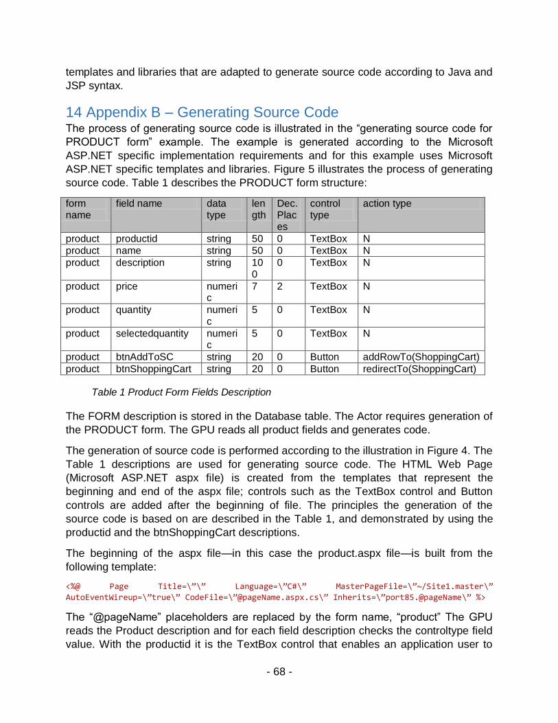
- 68 -
templates and libraries that are adapted to generate source code according to Java and
JSP syntax.
14 Appendix B – Generating Source Code The process of generating source code is illustrated in the “generating source code for
PRODUCT form” example. The example is generated according to the Microsoft
ASP.NET specific implementation requirements and for this example uses Microsoft
ASP.NET specific templates and libraries. Figure 5 illustrates the process of generating
source code. Table 1 describes the PRODUCT form structure:
form name
field name data type
length
Dec. Places
control type
action type
product productid string 50 0 TextBox N
product name string 50 0 TextBox N
product description string 100
0 TextBox N
product price numeric
7 2 TextBox N
product quantity numeric
5 0 TextBox N
product selectedquantity numeric
5 0 TextBox N
product btnAddToSC string 20 0 Button addRowTo(ShoppingCart)
product btnShoppingCart string 20 0 Button redirectTo(ShoppingCart)
Table 1 Product Form Fields Description
The FORM description is stored in the Database table. The Actor requires generation of
the PRODUCT form. The GPU reads all product fields and generates code.
The generation of source code is performed according to the illustration in Figure 4. The
Table 1 descriptions are used for generating source code. The HTML Web Page
(Microsoft ASP.NET aspx file) is created from the templates that represent the
beginning and end of the aspx file; controls such as the TextBox control and Button
controls are added after the beginning of file. The principles the generation of the
source code is based on are described in the Table 1, and demonstrated by using the
productid and the btnShoppingCart descriptions.
The beginning of the aspx file—in this case the product.aspx file—is built from the
following template:
<%@ Page Title=\”\” Language=\”C#\” MasterPageFile=\”~/Site1.master\” AutoEventWireup=\”true\” CodeFile=\”@pageName.aspx.cs\” Inherits=\”port85.@pageName\” %>
The “@pageName” placeholders are replaced by the form name, “product” The GPU
reads the Product description and for each field description checks the controltype field
value. With the productid it is the TextBox control that enables an application user to

- 69 -
enter the productid value interactively. For generating source code for the productid
field, the following TextBox template is used:
<asp:TextBox ID=\”@id\” runat=\”server\” OnTextChanged=\”@id_TextChanged\”> </asp:TextBox>
The placeholder @id is replaced by productid and added to the product.aspx file:
<asp:TextBox ID=“productid” runat=“server” OnTextChanged=“productid_TextChanged”></asp:TextBox>
To generate source code for btnShoppinCart field, the following Button template is
used:
<asp:Button ID=\”@id\” runat=\”server\” Height=\”34px\” Text=\”@text\” Width=\”184px\” OnClick=\”@id_Click\” />
The placeholder @id is replaced by btnShoppingCart and added to the product.aspx file
<asp:Button ID=“btnShoppingCart” runat=“server” Height=“34px” Text=“Shopping Cart” Width=“184px” OnClick=“btnShoppingCart_Click” />
The same process is applied to all PRODUCT forms fields and the fields are added to
the product.aspx file. The product.aspx file is closed by the </asp:Content> end tag.
The ASP.NET architecture can require a generation of the Code-Behind Class; in this
case, the product.aspx.cs file. The generation of this file is based on the same principles.
Generation of this file employs information stored in Table 1 and templates specific for
Code-Behind File and the GRA Libraries. The Code-Behind Class shall provide
implementation for each of Product form’s field events. In the case of the productid field,
it is the productid_TextChanged event that is called each time the productid field contents
are changed. The btnShoppingCart_Click event is called each time the mouse clicks on
the btnShoppingCart button. The productid_TextChanged and the btnShoppingCart_Click
methods are generated from the following templates:
protected void @id_TextChanged(object sender, EventArgs e)\n{\n
protected void @id_Click(object sender, EventArgs e)\n{\n
The @id is replaced by corresponding field name, and each method’s declaration is
closed by the end method parenthesis “}\n”. This is the resulting code that is appended
to the product.aspx.cs file:
protected void productid_TextChanged(object sender, EventArgs e) { logUserAction(“event=textchanged “, “control=productid”, “ value=“ +
productid.Text); } protected void btnShoppingCart_Click(object sender, EventArgs e)
{ logUserAction(“event=click “, “control=btnShoppingCart”, ““); Response.Redirect(“shoppingcart.aspx?cmdstr=add”); }

- 70 -
Either method can be considered implementation-specific. In both methods any kind of
C# source code can be inserted.
The btnShoppingCart_Click method redirects workflow to the shoppingcart.aspx page,
which is an action that is described in the action type column for the btnShoppingCart
field.
In the products.aspx.cs file can be inserted any other kind of source code, methods, or
declared variable. This is implementation-specific and how the form field will be mapped
to the method call is a design and implementation issue.
The GPU also generates the Data Object (DO) Class and SQL statements. It has
already been mentioned that the DO Class is used in the context of implementation of
Data Access Object pattern (Gamma et al. 1995). The DO Class is used to map
relational data to object data and for updating data stored inside of the database tables.
Although the Data Object (DO) Class and SQL are represented as two different source
code outputs from the GPU as seen in Figure 5, the generated SQL statements can be
appended or inserted in any other generated source code files, if necessary.
The process of generating the productDO.cs class is the same as for any other source
code file. It uses a class beginning and end template. The following is an example of the
source code from a generated productDO.cs class:
public class productDO : AbstractDO { public string productid; public string name;
public string description; public string price; public string quantity; public string selectedquantity; public string btnAddToShoppingCart; public string btnShoppingCart;
public const string DBNAME = “product”; public const string PRIMARY_KEY = “productid”; public const string PARENT_KEY = “productid”; public const string CHILD_KEY = “productid”; public productDO(){ } public override string createTable(AbstractDO abstractDO) {
string sqlstr = “CREATE TABLE `product` (productid VARCHAR(50), name VARCHAR(50), description VARCHAR(100), price decimal(7,2), quantity int(5), selectedquantity int(5), `tstamp` timestamp NOT NULL DEFAULT CURRENT_TIMESTAMP ON UPDATE CURRENT_TIMESTAMP ,PRIMARY KEY (productid) ) ENGINE=InnoDB DEFAULT CHARSET=utf8;”; return sqlstr; }
public override string dropTable(AbstractDO abstractDO) { string sqlstr = “DROP TABLE IF EXISTS “ + DBNAME; return sqlstr; } public override AbstractDO getClassName() {

- 71 -
return new productDO(); }
Besides each field declaration, the methods and SQL statements that support CRUD
operations are located in this class.
Creating a detailed description of this class does not make sense because the GPU
implementation as well as the templates and GRA Library methods are all
implementation-specific. The implementation presented in this chapter is the author’s
own design, and this implementation was created for research and experiment
purposes. How the requirement description will be structured and where it will be stored
is also implementation-specific.
Generating an application without manual programming assumes that the methods are
generic and can solve a class of related programming problems. Design patterns
(Gamma et al. 1995) can be a great inspiration for designing and writing general
purpose methods. Refactoring techniques (Fowler et al. 1999) can be used to learn
about improving code reusability. Analyzing design patterns, such as Data Access
Object, Abstract Factory (Bulajic and Jovanovic 2012), MVC pattern, and Strategy
Pattern, can be useful for designing general purpose methods.
15 Appendix C – Retail Store Example This chapter introduces an implementation example and the chapter’s purpose is to
inspire readers and let them perform further research for more specific examples on
their own.
The Retail Store application is developed by the Framework that is the implementation
of the GRA’s high-level design described in Figure 4, in Chapter 6 “Generalized
Requirement Approach Framework (GRAF)”. Figure 17 illustrates the GRA Framework
front-end design:
Figure 17 The GRA Framework Implementation v1
The first set of objects, circled in red, is responsible for requirement documenting. The
second set of objects, located in the next row following the objects in the red circle, are

- 72 -
the objects responsible for storing data in structured text format, which are used to
generate source code.
Displayed on the left side of the middle part of the screen are the GRAF objects in the
tree view structure. “A tree structure is a powerful tool for storing and manipulating all
kind of data, without differences is it used for natural language analysis, compiling
computer languages, or storing and analyzing scientific or business data. Algorithms for
searching and browsing tree structures are well known, and a numbers of tools for
manipulating tree structures are available for free in multiple computer languages”
(Bulajic and Filipovic 2012).
Displayed on the right side of the screen is each GRAF object’s attributes. The
attributes are guidelines for specifying a sufficient level of details for each of the GRAF
objects. Figure 18 illustrates the tree structure on the left side of the screen and the
GRAF objects’ attributes on the right side of the screen:
Figure 18 The GRA Framework Front End Design
The implementation of the GRA, the GRA Framework, is tested on the Retail Store
application. The Retail Store is a fictive E-Commerce application and is described by
the RetailStoreProject User Story in Chapter 7 “GRA Framework Validation”. Figure 19
illustrates the RetailStoreProject User Story:

- 73 -
Figure 19 Retail Store Project
From the RetailStoreProject User Story is possible to identify:
ProductComponent object
Sales Operation
The ProductComponent is described as “a sale article that is described by a product
identification number, product name and description, available quantity, and price” and
is used “to provide a list of products for on-line sale”. Figure 20 shows all
ProductComponent objects:

- 74 -
Figure 20 Product Component
The ProductComponent contains:
FormsContainer
UserStoryContainer
These two containers are used for storing Forms design information and the User Story,
SalesDepartmentStory, and AddProductToShoppingCartUC Use Cases.
In the SalesDepartmentStory described in Chapter 7 “GRA Framework validation” are
the Sales Department and Salesman expectations. The SalesDepartmentStory is
described in more detail by the AddProductToProductListUC Use Case. Figure 21
illustrates the Use Case template and guidelines and reveals more details about the
Product object:

- 75 -
Figure 21 AddProductToShoppingCartUC Use Case
Described in the AddProductToShoppingCartUC Use Case are all the steps and the
order of execution to add a product to the shopping list. The Use Case object is a
template and guideline for creating a Use Case. The Framework enables a user to add
a new step, or update or delete an existing step feature.
If it is necessary to review why this Use Case is essential, a mouse click on the parent
node, BuyerStory, will explain it to the user. The BuyerStory User Story is reused in the
ShoppinCartComponent. This will be demonstrated later. Although this User Story is
assigned to two different nodes and components, there is only one instance of this
story. It means that any BuyerStory changes will be reflected to all nodes. While this
feature is an advantage for documentation, it can create a side effect of defects,
because changes will affect an unknown number of objects.
Figure 22 illustrates the Test Case template and guidelines:
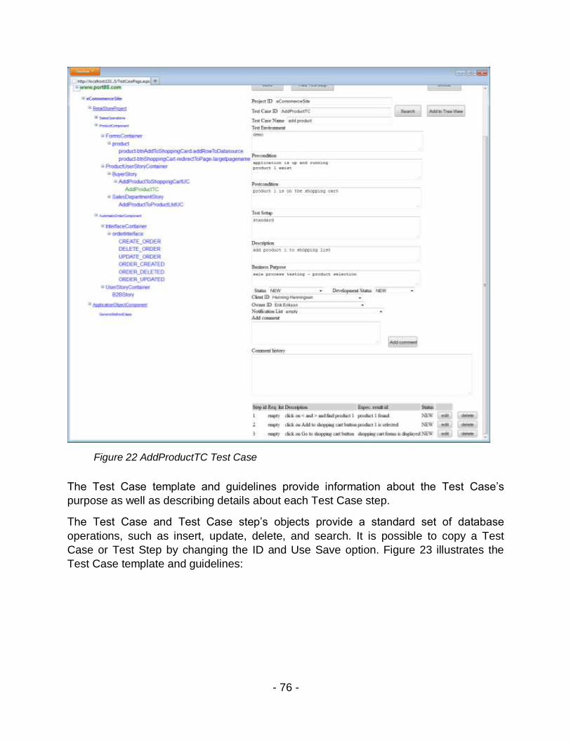
- 76 -
Figure 22 AddProductTC Test Case
The Test Case template and guidelines provide information about the Test Case’s
purpose as well as describing details about each Test Case step.
The Test Case and Test Case step’s objects provide a standard set of database
operations, such as insert, update, delete, and search. It is possible to copy a Test
Case or Test Step by changing the ID and Use Save option. Figure 23 illustrates the
Test Case template and guidelines:

- 77 -
Figure 23 AddProductTC Test Step
The Framework enables adding, moving, and deleting each object or node. The deletion
of a node will update tree view, but the node’s description and corresponding node
object will still exist and can be reused by another node
The ProductComponent contains the FormsContainer node. The FormsContainer in this
implementation is used for design structuring purposes. While the previously mentioned
objects are used for design and documenting purposes, the Forms object is used by the
Generator to generate source code and executables. Figure 24 illustrates the Forms
objects template and guidelines:

- 78 -
Figure 24 ProductForms Forms
The decision about where in the hierarchy to put a Forms object can be important for a
better design understanding. For experimental purposes, the product Forms is assigned
to the FormsContainer. Another possibility would be to add product forms to the User
Story or Use Case node. The product forms can be described by more than one User
Story and Use Case. To resolve the M:N (many to many) relationship within database
modeling, it is necessary to create a complex entity that contains IDs from both involved
entities. Under the circumstances of the tree structure this relationship should not be an
issue as long as the same product form is a unique object. This means that there is only
one instance of the same product forms stored in the permanent storage. Here it is
possible to assign product forms as top level nodes and assign related User Stories,
Use Cases and Test Cases to the descendent nodes. This can be considered upside-
down logic, because the User Stories specify a Forms object.

- 79 -
This dilemma is not easy to resolve and it illustrates the need for different views of the
same design structure. Different views and design structure transformations improve the
system’s understanding and relations between objects and structures. The tree
structure’s transformation capability fits well to these requirements.
In this case, the design choice has been driven by requirements to clearly demonstrate
method implementation and the Framework’s objects. That is the reason why it was
necessary to create the FormsContainer to demonstrate the Forms object templates
and guidelines.
The Forms object describes forms fields, field’s type and length, and a set of triggers
that can be assigned to the forms level and to the each forms field. While the field’s
purpose is to accept user inputs and commands, triggers represent processing actions
that software products should execute after the rising of event. These events can be
raised on the forms level or on the field level. These actions can be simple, such as
redirecting a Web page to another URL, but they can also be complex and can require
complex algorithms, access to the complex data structures and relations, and require
complex validation. Figure 25 illustrates the template and guideline for defining form
fields:

- 80 -
Figure25 Product Forms Fields
The Forms field’s description provides information about field data type, field size, field
type—such as a database or a memory field—and what the Generator uses to decide if
it is necessary to provide a place for a field value in the permanent storage or if it is a
temporary variable that will disappear after processing. There are a number of Y/N
options that provide detailed information about a field’s significance, visibility, field
validation and lookup data sources, and about triggers and actions, as well as the
control type used to create a field’s representation in the Forms object. The control type
is important not only because of the design issues, but also because the control type
decides what kind of events can be assigned to a particular control type. For example,
in the case of Microsoft .NET, it is possible to assign to the Button control an OnClick
event, but this kind of event does not exist in the event of the TextBox control.
Figure 26 illustrates the Add Action to Forms Fields template and guidelines:

- 81 -
Figure 26 Add Action addRowToDataSource
The Forms ID and Field ID are forms and forms fields’ unique identifiers. The App.
Object ID, Method ID, and Parameter ID are class, method, and parameter identifiers.
The Generator translates this to the code that is assigned to the forms fields and is
executed when an event on that field is fired. In this particular case when a click event is
fired on the btnAddToShoppingCart fields, it will call upon an addRowToDatasource
method and this method’s parameter, targetdatasourcename, will be set to the
“shoppingcart” value.
When a method requires more parameters, the Parameter ID dropdown list contains the
parameter list and to each parameter it is possible to add a field or a value. This is
illustrated in Figure 27:

- 82 -
Figure 27Add Action Parameter List
This is a straightforward process and is guided by the Framework’s ApplicationOb ject
object and applicationobjectmethodsparameters_formsfields entity. In the above
example, the sqlMathExpression requires two parameters: the first parameter is
datasourcename and the second parameter is sqlmathexpression.
Figure 28 illustrates the generic methods used for creating an example application:

- 83 -
Figure 28 ApplicationObject Component GenericMethodClass
To be able to execute method and assign parameters, the class and method should
already exist. Another requirement is that class and method should be generic and
should adapt the execution to parameter values.
To build this example application, research identified following the five procedures:
addRowToDatasource – adds current objects’ data to the output data source.
Used to add product to the ShoppingCart as well as for adding ShoppingCart
items to Order,
updateRowToDatasource – updates row in the database by using current object
data. Used to update Order with delivery info.
sqlMathExpression – for calculation based on the data stored in the SQL tables.
Used for calculating the total price of the product items,
mathFormula – calculation based on math operations. Used for calculations that
can be expressed by implementation language notation and available mat
functions, and is executed on the numeric data stored in the application internal
memory. In this particular case, it is used for calculating the Order’s total amount,
redirectToPage – moves workflow to the next Web page. Used for navigation
purposes and changing application workflow

- 84 -
Writing the redirectToPage method in generic code is a simple task, because this
method needs a target page name and eventual parameters list. Writing the math
Formula, however, requires more time to be designed to remove the complexity and the
sqlMathExpression needs more effort to make the method reusable,
The real complex methods for most programmers are algorithms where detailed data
model relations are involved. To reduce this kind of complexity, the data model built by
the Generator is simple and this model is not normalized. Normalization and entity
relations increase the processing complexity and require access to multiple tables,
storing and keeping track of temporary results, and enabling transaction management.
In the case of the GRA Framework implementation, the simplicity is the preferred
approach. Data normalization, code optimization, and security, according to this
method, were moved to the next step where developer specialists and experts are
involved for each task.
The steps in the ProductComponent design demonstrate the design process and the
use of the Framework’s objects. The tree view is built from the predefined set of objects
and each node description is a template that provides the sufficient number of details for
specifying each selected object. The SalesOperation component design is illustrated in
Figure 29:
Figure 29 SalesOperation Component
The SalesOperation component contains the PaymentOperations and
ShoppingCartComponent. The PaymentOperations component contains the
PaymentDemoComponent and ShoppingCartComponent. These components are built
using the same Framework objects as the ProductComponent. Figure 30 illustrates
these components’ internal design:

- 85 -
Figure 30 SalesOperation Component Design Details
The FormsContainer in the PaymentDemoComponent contains two different forms
objects, paymentdemo forms and deliveryinfo forms. The reason for two forms is that
payment options require the provision of a delivery address (deliveryinfo forms) and
credit card details (paymentdemo forms).
The OrderAndInvoiceComponent contains the Order and Invoice components. In a real-
life project these two components are separated. The reason to keep these two together
here is to simplify the example application.
The last step in this process is generating source code and executables. Generated
source code and executables are used for requirement validation, and any further work
is directly dependent on the validation results. The Generator already utilizes a defined
object from the design components. The forms are used for requirement visualization,
test, and validation of future product features. The generated source code and
executables are used to validate a sufficient level of detail.
For example, the mathFormula assigned to the orderdemo forms total field is described
as “itemstotal + handlingfee + ( itemstotal + handlingfee ) * vatamount / 100”
If any of the operands is missing, the compiler will issue an error.
If any of operand contains an illegal value, such as a null value, the compiler will issue
an error.

- 86 -
If there are no compiler errors, the executables will enable testing of the math formula
by assigning different values to each or a selected number of operands, and display the
calculation results. Figure 31 illustrates the orderdemo forms design:
Figure 31 Math Formula Example
To enable validation, it is necessary to generate source code and executables. This job
is accomplished by the Generator. The Generator reads each Framework object
design’s information and translates it to the C# source code. Before the Generator is
involved the desired design object and Generator options should be selected, and then
the Generator is involved with a single click on the Generate Code button.
Figure 32 illustrates this button position and options:

- 87 -
Figure 32 Generate Code
In the dropdown list are the options for creating code_only, code_and_datasource,
datasource_only, or for altering code and data source. This version of the Framework
implements the two first options, code_only and code_and_datasource options.
When each of the Forms is selected and generated, the Framework will redirect
workflow to the generated page. Figure 33 illustrates the Generate Code result:

- 88 -
Figure 33 Product Forms Generated
On the left side of the screen is the navigation tree that shows all the generated objects.
On the right is the last generated forms display. The Framework’s job is accomplished
when the source code and executables are generated. The Framework has nothing
more to do with validation and code execution. Responsible for the code testing and
validation are the customers and requirement negotiation team. The code is adapted to
be executed inside of a Microsoft Visual Studio environment and future testing and
validations are executed in a development and test environment.
Generated forms are fully functional applications. On the top of the product forms are
previous (“<”) and next (“>”) navigation buttons, as well as “Save” and “Delete” buttons.
The insert and update row functions are attached to the “Save” button. If a row already
exists it will be updated, otherwise a new row will be inserted. This task belongs to the
standard functionality that is assigned to each form and is created by the Framework.

- 89 -
Methods from the GenericMethodClass are assigned to the “Add to ShoppingCart” and
“Shopping Cart” buttons, as described in the Figure 28. The “redirectToPage” method
assigned to “Shopping Cart” button is a generic method that can be used to test
application workflow.
In Figure 33 is evidence of a cosmetic defect. The “Add to Shopping Card” button title
should be renamed to “Add to Shopping Cart” title. A Defect can be added to the design
and to the place where defect occurs, the product forms.
The Figure 34 shows AddToShoppingCardDefect in the FormsContainer and product
form design:
Figure 34 Product Forms Defect
In Figure 34, the AddToShoppingCardDefect is assigned to the product form. The
product form has two action buttons designed, and to the btnAddToShoppingCard field
is assigned a addRowToDatasource application object method and to the
btnShoppingCart is assigned a redirectToPage application object method.
The Generator generates each designed object according to the definitions that are
stored in the permanent storage, and creates a fully functional application that is able to

- 90 -
receive user inputs and store inputs in the permanent storage, and process data
according to the design requirements. Figure 35 illustrates more actions that are
assigned to the orderdemo form fields:
Figure 35 Orderdemo Designed Actions
The tree view shows each of designed actions and forms fields where action is
assigned. When a form is generated, the Framework redirects to the form Web page.
Figure 36 illustrates the orderdemo Web page:

- 91 -
Figure 36 Orderdemo Forms Generated
The orderdemo form is interesting because to this form are assigned math functions
that calculate the Items Total amount and order Total amount, based on the number of
product items, item price, VAT amount, and handling fee amount. In Figure 36 the
orderdemo form design details are displayed.
The orderdemo form test is described in Chapter 16.2.8 “Calculate Order Items Total”
Use Case, in Chapter 16.2.9 “Calculate Order Total With Handling Fee” Use Case, and
in Chapter 16.2.10 “Calculate Order Total With VAT” Use Case. Figure 37 shows the
expected results according to the test described in Chapter 16.2.8 “Calculate Order
Items Total” Use Case:

- 92 -
Figure 37 Orderdemo Form Initial Test
The Items Total initial value is set to 5. This means that the generic methods attached to
the Items Total have been fired and calculated the Selected Quantity * Price for each
order item.
The Total is set to 5 and is correct because the Handling Fee and VAT amount are set
to 0, but this test cannot confirm that the Total calculation is working as expected. To be
sure that this calculation is triggered and is working as expected, it is necessary to
change these two values.

- 93 -
Figure 38 shows the expected results according to the test described in Chapter 16.2.10
“Calculate Order Total With VAT” Use Case:
Figure 38 Orderdemo Form Handlingfee and Vat amount Changed Test
The Items’ Total amount is correct and is not changed. The Total amount is changed
and is correct according to the designed calculation “5 + (5 + 1) * 10 /100 = 6.6”.
This test confirms that calculations are triggered and executed according to the design
information created by the GRA Framework, and confirms that the designed operands
are used correctly in the calculations.

- 94 -
16 Appendix D – Retail Store Test Documentation “Beware of bugs in the above code; I have only proved it correct, not tried it.” (Donald
Knuth)
This chapter is dedicated to the validation of the generated source code and testing of
the Retail Store application. The development effort in this dissertation has been
focused on proving that the functional requirements are working, and in this
implementation of the GRA Framework only the errors that prevent application
execution or the appearance of incorrect operation results are corrected. The Use
Cases used for the Retail Store application testing, where the primary focus is on the
successful scenario workflow and where alternative scenarios are ignored, reflects this
intention.
For the implementation of the GRA, only the available technical platform features are
used to reduce the amount of work necessary to develop code for employing that which
can be reused. Such features are implementation-specific and different technical
platforms would require different solutions. In this dissertation the following technical
platform is used:
Microsoft Windows 7 Professional Operating System (OS)
Microsoft .NET Framework version 4.5.50709
Microsoft ASP.NET version 2012.3.41009
Microsoft Visual Studio Express 2012 for Web
Microsoft C# language
Oracle MySQL database version 5.6.10.1
Oracle MySQL Connector NET version 6.6.5
In this software list only Microsoft Windows 7 Professional Operating System (OS)
requires a payable license. The other software that belongs to the technical platform
can be downloaded free of charge from the Microsoft and Oracle Web sites. Each
product contains a detailed installation guide.
Although the presented solution is sufficient for demonstrating method implementation
and the generation of source code, this is not yet a software product and this
implementation solely has academic and research purposes.
16.1 Generated Source Code Validation The generated source code is validated by a:
Compiler
Runtime environment

- 95 -
Using the compiler and runtime environment for generated code validation fits well to
the GRA's basic philosophy to use already available technical platform features to
reduce the amount of the work necessary for developing code to implement that which
can be reused.
The workflow diagram in Figure 39 describes source code validation process:
Figure 39 Generated Source Code Validation
The source code generated by the GRA Framework is immediately available for the MS
Visual Studio Express 2012 for the Web, and the GRA Framework tries to execute the

- 96 -
generated source code. Before the generated code can be executed, the MS Visual
Studio needs to compile it. The ASP.NET/C# compiler will check syntax and semantics,
parsing and preprocessing, and report any kind of compiler errors. If there is a compiler
error, such as an undefined variable or reference to an undeclared class or method, the
user may be able to correct it by changing the descriptions in the GRA Framework;
otherwise, the error needs to be reported as a Defect. A compiler error can be related to
the wrong MS Visual Studio version or a missing installation of the correct Microsoft
.NET framework. Such kinds of errors should be corrected by the installation of the
software versions required by technical platform described in Chapter 16 “Appendix D –
Retail Store Test Documentation”.
If compilation is accomplished successfully, then the ASP.NET Development Server—
the Web server delivered as a part of the MS Visual Studio installation package—
executes a generated source code. The Client's access to the application code is
achieved using a Web browser. When the code is executed, a runtime error can occur.
The runtime errors are usually related to an improper technical platform software
installation or to the corrupted database files or configuration files. The runtime error
example can be missing the connection to the MySQL database, which can be caused
by a missing or incorrect installation of Oracle MySQL Connector NET version 6.6.5. If
the runtime error cannot be corrected then it is reported as a Defect. The Defect
reporting’s primary purpose is to keep track of issues that need to be implemented in
the next version.
16.2 Retail Store Functional Testing The Use Cases presented in this chapter are used to test the Retail Store application.
The Use Cases are based on the following User Stories described in Chapter 7 “GRA
Framework Validation”:
The RetailStoreProject
The BuyerStory
The SalesDepartmentStory
While the RetailStoreProject User Story describes requirements related to the
application architecture, the Retail Store functional requirements are described in the
BuyerStory User Story and SalesDepartmentStory. Figure 6 describes the Retail Store
application workflow.
The test of the implementation has been focused on proving that the functional
requirements are working and in this implementation of the GRA Framework, only errors
that prevent application execution or a display of incorrect operation results are
corrected. The Use Cases used for the Retail Store application testing—where the
primary focus is on the success of the scenario workflow and alternative scenarios are
ignored—reflects this intention.

- 97 -
16.2.1 Save Button Add Record
Name Save Button Add Record
Scope Web Interface, Back-end, database
Primary Actor User
Precondition Internet connection, Web Browser is running, connection to URL
http://www.port85.com//test/eCommerceSite/product.aspx?cmdstr=null
Record Product ID = 1 and Product ID = 2 do not exist
Post-
condition
Brief
Description
Save Button adds new record to the database table
Main Scenario 1. Enter URL address in the Web Browser address field and press
ENTER
2. Browser displays: Projectt > eCommerceSite.product form.
3. Enter : Product ID = 1, Name = 1, Description = 1, Price = 1,
Quantity = 1, Selected Quantity = 1
4. Click Save button.
5. Browser resets all fields described in step 3
6. Enter: Product ID = 2, Name = 2, Description = 2, Price = 2,
Quantity = 2, Selected Quantity = 2
7. Click Save button.
8. Click on the “>” button
9. Browser displays record Product ID = 1
10. Click on the “>” button
11. Browser displays record Product ID = 2
Alternate
Scenario
Business
Rules If the record Product ID exists, the fields described in the step 3
will not be reset
If the record Product ID exists and any field’s value is changed,
after clicking on Save button the record will be updated with the

- 98 -
changed field value
Special
Requirements
Parent Use
Case
Child Use
Case
Reference SalesDepartmentStory User Story, described in the Chapter 7 “GRA
Framework Validation”
Success
criteria
The currently entered record is added to the database table.
16.2.2 Save Button Update Record
Name Save Button Update Record
Scope Web Interface, Back-end, Database
Primary Actor User
Precondition Save Button Add Record Use Case successfully executed
Record Product ID = 2 does exist
The currently displayed record is record where Product ID = 2 Post condition
Brief Description Save Button updates currently selected record
Main Scenario Continue after step 12 Main Scenario in Save Button Add
Record Use Case.
1. Enter : Quantity = 5
2. Click Save button.
3. Click on the “>” button until you get Product ID = 2
4. Browser displays record where Product ID is 2 and
Quantity = 5
Alternate Scenario
Business Rules If the record Product ID exists and any field’s value is
changed, after clicking on Save button the record will be

- 99 -
updated with the changed field value
Special
Requirements
Parent Use Case Save Button Add Record
Child Use Case
Reference SalesDepartmentStory User Story, described in Chapter 7 “GRA
Framework Validation”
Success criteria The currently changed record is updated in the database table.
16.2.3 Delete Button
Name Delete Button
Scope Web Interface, Back-end, Database
Primary Actor User
Precondition Save Button Add Record Use Case successfully executed
The currently displayed record is record where Product ID = 2
Post-condition
Brief Description Delete Button deletes currently selected record
Main Scenario Continue after step 12 Main Scenario in Save Button Add
Record Use Case.
1. Click on the “Delete” button
2. All fields are set to empty values
3. Click on the “>” button and verify that record Product ID
= 2 does not exist
4. The current record is Product ID = 1
5. Click on the “Delete” button
6. Click on the “>” button and verify that record Product ID
= 1 does not exist
Alternate Scenario
Business Rules
Special

- 100 -
Requirements
Parent Use Case Save Button Add Record
Child Use Case
Reference SalesDepartmentStory User Story, described in Chapter 7
“GRA Framework Validation”
Success criteria The currently selected record is deleted from the database
table.
16.2.4 Browse Buttons
Name Browse Buttons
Scope Web Interface, Back-end, Database
Primary Actor User
Precondition Save Button Add Record Use Case successfully executed
The currently displayed record is record where Product ID = 2
Post-condition
Brief Description Delete Button deletes existing record
Main Scenario Continue after step 12 Main Scenario in Save Button Add
Record Use Case.
1. Click on the “<” button
2. Verify that currently selected record changes to
Product ID = 1
3. Click on the “>” button
4. Verify that currently selected record changes to
Product ID = 2
Alternate Scenario
Business Rules
Special
Requirements
Parent Use Case Save Button Add Record
Child Use Case

- 101 -
Reference SalesDepartmentStory User Story and BuyerStory User
Story, described in Chapter 7 “GRA Framework Validation”
Success criteria Browse through list of the available records.
16.2.5 Add To Shopping Cart Button
Name Add to Shopping Cart Button
Scope Web Interface, Back-end, Database
Primary Actor User
Precondition Browse Buttons Use Case successfully executed
The currently displayed record is record where Product ID = 2
Post-condition
Brief Description Add to Shopping Cart Button adds selected record to the
shopping cart list
Main Scenario Continue after step 4 Main Scenario in Browse Buttons Use
Case.
1. Click on the “Add to Shopping Cart” button
2. Click on the “<” button
3. Verify that currently selected record is changed to
Product ID = 1
4. Click on the “Add to Shopping Cart” button
5. Click on the “eCommerceSite.shoppingcart “link in the
navigation bar on the left side of the screen
6. Verify that currently displayed form is Project >
eCommerceSite.shoppingcart form
7. Click on the “>” button
8. Verify that currently displayed record is Product ID = 1
9. Click on the “>” button
10. Verify that currently displayed record is Product ID = 2
Alternate Scenario

- 102 -
Business Rules
Special
Requirements
Parent Use Case Browse Buttons
Child Use Case
Reference BuyerStory User Story, described in Chapter 7 “GRA
Framework Validation”
Success criteria The shoppingcart list contains Product ID = 1 and Product ID
= 2 records.
16.2.6 Create Order
Name Create Order
Scope Web Interface, Back-end, Database
Primary Actor User
Precondition Add to Shopping Cart Button Use Case successfully
executed
Post-condition
Brief Description Create Order creates order items from the shoppingcart list
Main Scenario Continue after step 10 Main Scenario in Add to Shopping
Cart Button Use Case.
1. Click on the “Add to Order” button
2. Click on the “<” button
3. Verify that currently selected record is changed to
Product ID = 1
4. Click on the “Add to Order” button
5. Click on the “eCommerceSite.orderdemo” link in the
navigation bar on the left side of the screen
6. Verify that currently displayed form is Project >
eCommerceSite.orderdemo form
7. Verify that in the order items list are Product ID = 1 and
Product ID = 2 items

- 103 -
Alternate Scenario
Business Rules
Special
Requirements
Parent Use Case Add to Shopping Cart Button
Child Use Case
Reference BuyerStory User Story, described in Chapter 7 “GRA
Framework Validation”
Success criteria The selected shoppingcart list records are added to the list of
order items.
16.2.7 Delivery Info
Name Delivery Info
Scope Web Interface, Back-end, Database
Primary Actor User
Precondition Create Order Use Case successfully executed
Post-condition
Brief Description Delivery Info adds delivery information to the order items from
the shoppingcart list
Main Scenario 1. Click on the “eCommerceSite.deliveryinfo” link in the
navigation bar on the left side of the screen
2. Enter: Customer Id = testcustomer, Customer Name =
TEST_CUSTOMER, Delivery Address = Kongens
Lyngby 48, ZIP code = 2800, Delivery City =
Copenhagen, Delivery Country = Denmark
3. Click on the “Update Order” button
4. Click on the “eCommerceSite.orderdemo” link in the
navigation bar on the left side of the screen
5. Verify that the currently displayed form is Project >
eCommerceSite.orderdemo form
6. Click on the “>” button
7. Verify that Customer Id = testcustomer, Customer

- 104 -
Name = TEST_CUSTOMER, Delivery Address =
Kongens Lyngby 48, ZIP code = 2800, Delivery City =
Copenhagen, Delivery Country = Denmark
Alternate Scenario
Business Rules
Special
Requirements
Parent Use Case Create Order
Child Use Case
Reference BuyerStory User Story, described in Chapter 7 “GRA
Framework Validation”
Success criteria Delivery information is added to the orderdemo.
16.2.8 Calculate Order Items Total
Name Calculate Order Items Total
Scope Web Interface, Back-end, Database
Primary Actor User
Precondition Delivery Info Use Case successfully executed
Post-condition
Brief Description Calculate order Items Total according to the following formula:
Items Total = (Selected Quantity 1 * Price 1) + (Selected
Quantity 2 * Price 2) + (Selected Quantity n * Price n)
Main Scenario Continue after step 7 Main Scenario in Delivery Info Use
Case.
1. Click on the “<” button
2. Verify that Items Total = 5
3. Click on the “Update Order” button
4. Click on the “eCommerceSite.orderdemo” link in the
navigation bar on the left side of the screen
5. Verify that currently displayed form is Project >

- 105 -
eCommerceSite.orderdemo form
6. Click on the “>” button
7. Verify that Customer Id = testcustomer, Customer
Name = TEST_CUSTOMER, Delivery Address =
Kongens Lyngby 48, ZIP code = 2800, Delivery City =
Copenhagen, Delivery Country = Denmark
Alternate Scenario
Business Rules
Special
Requirements
Parent Use Case Delivery Info
Child Use Case
Reference BuyerStory User Story, described in Chapter 7 “GRA
Framework Validation”
Success criteria Order Items Total = 5, which is calculated from the two order
items, products 1 and 2, according to the formula (1 * 1) + (2 *
2) = 1 + 4 = 5
16.2.9 Calculate Order Total With Handling Fee
Name Calculate Order Total With Handling Fee
Scope Web Interface, Back-end, Database
Primary Actor User
Precondition Calculate Order Items Total Use Case successfully
executed
Post-condition
Brief Description Calculate order Total according to the following formula: Items
Total = itemstotal + handlingfee + ( itemstotal + handlingfee )
* vatamount / 100
Main Scenario 1. Enter: Handling Fee = 1 and press ENTER key
2. Verify that Total = 6

- 106 -
Alternate Scenario
Business Rules
Special
Requirements
Parent Use Case Calculate Order Items Total
Child Use Case
Reference BuyerStory User Story, described in Chapter 7 “GRA
Framework Validation”
Success criteria Order Total = 6 what is calculated from the two order items,
and handling fee Total = 5 + 1 + (5 + 1 ) * 0/100 = 5 + 1 + 0 =
6
16.2.10 Calculate Order Total With VAT
Name Calculate Order Total With VAT
Scope Web Interface, Back-end, Database
Primary Actor User
Precondition Calculate Order Total With Handling Fee Use Case
successfully executed
Post-condition
Brief Description Calculate order Total according to the following formula: Items
Total = itemstotal + handlingfee + ( itemstotal + handlingfee )
* vatamount / 100
Main Scenario 1. Enter: VAT amount = 10 and press ENTER key
2. Verify that Total = 6.6
Alternate Scenario
Business Rules
Special
Requirements
Parent Use Case Calculate Order Total With Handling Fee

- 107 -
Child Use Case
Reference BuyerStory User Story, described in Chapter 7 “GRA
Framework Validation”
Success criteria Order Total = 6.6, which is calculated from the two order
items, and handling fee Total = 5 + 1 + (5 + 1 ) * 10/100 = 5 +
1 + 0.6 = 6.6
16.2.11 Credit Card Payment
Name Credit Card Payment
Scope Web Interface, Back-end, Database
Primary Actor User
Precondition
Post-condition
Brief Description Layout for entering credit card information for online payment
Main Scenario 1. Click on the “eCommerceSite.paymentdemo” link in the
navigation bar on the left side of the screen
2. Enter: Payment Id = 1, Credit Card Name = VISA,
Credit Card Number = 1234567890123456, Expiration
Month = 1, Expiration Year = 19, Code Number = 123
3. Click on the “Confirm Payment” button
4. Verify that all form fields are empty
Alternate Scenario
Business Rules
Special
Requirements
Parent Use Case
Child Use Case
Reference BuyerStory User Story, described in Chapter 7 “GRA
Framework Validation”
Success criteria It is possible to enter credit card information.