First Results of GPS data and the contribution for water loading evaluation in Amazon Basin
Upload
truongduongCategory
view
226download
1
CONTRIBUTION TO LOADING TEST PROCEDURE Of GROUND ANCHORS
Contribution à la méthode d'essais des tirants d'ancrage
by
B.K. MAZURKIEWICZand
T. NAJDERGdansk Technical University, Gdansk - Poland
SOMMAIRE
La communication contient les principaux renseignements sur la technologie de construction etsur les méthodes d'essais de la résistance d'ancrages temporaires ou permanents installés dansla structure d'une cale sèche. Des analyses particulières furent faites pour le choix de la meilleureméthode de perforation et son influence sur larésistance obtenue pour des ancrages dans dessols sableux intercalés de lits d'argile. Les essaisde tirants ont été faits à partir d'un· programmemodifié de la norme DIN 4125, cependant qu'unecomparaison des résultats obtenus en utilisantdifférentes méthodes connues dans le monde, apermis de définir la meilleure. Au cours desessais, on a cherché à obtenir des informationssur l'influence du temps qui s'écoule entre laconstruction des ancrages et l'essai de chargement sur l'amplitude des déformations et la résistance des ancrages. Le frottement sur la longueurlibre de l'ancrage et la préservation de cettelongueur ont aussi été étudiés en fonction de laméthode de construction. Enfin, des chargementsrépétés des mêmes ancrages ont été faits quipermettent de donner des conclusions sur l'influence de ce facteur.
D'après les observations et les résultats desessais in situ, une analyse théorique est présentéede la stabilité des murs de soutènement ancréset des fondations soumises à des tractions.
SUMMARY
The paper contains basic data on the technologyof construction and on the testing methods ofbearing capacity of ground anchors, temporaryand permanent, installed in the structure of a drydock. Particula.rly analyses were made concerning the choice of a proper drilling method and itsinfluence on the bearing capacities obtained ofanchors in sandy soils with clay interbeddings. Thetests of the bearing capacity of the ground anchorswere made according to a modified program basedon the results of an analysis of the method given byDIN-4125, whilst a comparison of results obtainedusing different methods known in the world, hasoffered the possibility of definirs the most adequateone. During the tests, efforts were made to obtaindata on the influence on the magnitude of deformations and bearing capacities of the anchors of thetime period, between the construction of theground anchor and the loading test. Also themagnitude of friction of the free part of theanchor and the preservation of this length asdependent on the construction method were considered. Additionally repeated loadings of the sameanchors were made, and conclusions made concerning the influence of this factor.
The theoretical analysis concerns the problemof the stability of anchored retaining walls and offoundation subjected to tension forces, based onobservations and test results made on the site.
1. INTRODUCTION
During construction of a dry dock, ground anchorswere used as permanent anchors of sheet wallsof the dry dock ,wall and as temporary anchors ofspecial foundations used for erection of a heavy gantrycrane. Analyses were particularly made concerning thechoice of a proper drilling method and its influenceon the bearing capacity of the above anchors in sandysoils with clay interbeddings. AlI anchors were testedby means of loading tests made according to a modifiedprogram based on the result of an analysis of the(German standard DIN, 4125) method. _A comparisonof results obtained using diff~rent methods known
87
throughout the world has shown that .the chosenmethod can be the most adequate one.
The performed tests, described in the paper, weremade with an assulnption that the results obtainedwould deliver information about the influence ofthe time period which elapsed between the construction of the ground anchor and the loading test,on the magnitude of deformations and bearing capacities of the grotind anchors. Also the magnitude offriction of the free part of the anchor and the preservation of this length as dependent on the constructionmethod were considered, whilst repeated loadings ofthe same anchors should bring results on the influenceof these loadings on the bearing capacity.
2. CONSTRUCTION Of GROUND ANCHORS
The permanent ground anchors investigated weremade using the rotary-percussive drill method called«Alvik-X». Casing tubes 3.5 and flushing water wereintroduced on the free length equal to 17.0 m.The crawler drill on wheels was of the Atlas Copcotype BVB-33 whilst the tubes and extension rodswere placed in the soil by power rotated drill(top hammer) of the BBE 57-01 type. Number ofof blows == 1950/60 s, torque moment == max. 80 kpm,inclination == 1:3. The boring along the length bondto ground, equal to 10.0 m, was performed using thesame method but without casing tube and with bentonitflushing. After the assumed depth has been reached thebentonit suspension was pressed out by cement grout(aqueous colloidal dispersion) with w/ c == 0.4 to 0.5Through raising the grout from the hole bottom levelconcreting of the borehole took place whilst at thesame time through the upper end of the tube therewas a discharging of the ground and bentonite Thepressing of grout was stopped about 5 min aftera total removal of bentonit flushing occured. Immediately after grouting a 7.5 0 Bridon wire strandwith centralisers placed in 2.0 rn_distance along thewhole anchoring length was pressed in the grout.Grouting tubes were also installed. To avoid concreting of steel strands along the free length specialpackers were used.
Once the strands in the grout the anchor head. wasclosed and the pressure was raised to about 15 at(1.5 N/mm2) to increase the bond of the anchorto the ground. One week after concreting of theanchor a prestressing tests was made by means of ahollow ram multi strand jack VSL for a force of 88 Mpon one anchor. The loading force was then low~red
to working load of 59 Mp.The temporary anchors were made using the over
burden drilling method (00) with a very rich waterflushing. Reaching the assumed depth, the waterflushing was replaced by cement grout of w/c == 0.4.The hole was filled with grout from the bottom levelusing flexible tubes. The reinforcement consists of
"7.5 0 wire strands but without centralisers. Thepulling out of casing tubes was connected with additionof grout to keep a constant grout level in the hole.Once the casing tube pulled out a 6.0 m long injectionpipe with one way valve was placed. By means ofthis pipe the injection was performed under a pressureof 7 at (0.7 N/mm2). Seven days later the anchorswere prestressed to 90 Mp. After prestressing the
.loading was loweied to 72 Mp.Both methods used for construction of perma
nent and temporary anchors, belong to the rotary-
percussive drill method." The action of the bit isa combination of torque and impact with a highfrequency, and of axial thrust. It causes a very effective remoulding of the ground whilst the removal ofthe remoulded ground is assured by water flushing.To obtain an optimum interaction between the groundand the anchor, the remoulding of the ground aroundthe casing tube should extend as low as possible whilstthe water flushing should be limited as much as possible. "These conditions are fuifilled using the Alvik-X system,depending on the action of an eccentric bit boring ahole which has a diameter slightly bigger than thediameter of the casing tube. The tube penetrates byfollowing the bit but it does not rotate. This causesa lesser remoulding of the soil along the tube shaft.. Thebit, because of the impact and torque, cuts thesoil simultaneously by the bit part and the reamer. Thewater flushing is discharged through extension rodsand holes in the bit which has a special constructedguide. This guide protects the pipe from inflow ofsoil what means that a certain amount of grains ispressed back into the soil whilst through the tube onlywater flushing is discharged. In sandy soils it givesa big increase of density.
In the OD-method the bit and the tube are in thetip protected by a ring. They are under a torque andimpact transmitted by a common part, namely theshank adapter. In the described cases, however, asimplified OO-method was used. The penetrationtook place using only casing tube whilst the soilfrom the tube was removed by water flushing.
Analyzing both methods and the bearing capacitiesof anchors obtained it can be stated that the 00method which seems to be simpler and needs lesswork, does not give any significant increase of efficiency when compared with the Alvik-X method.The remoulding of the ground when using water flushing and casing pipes, as occurs in the OO-method, hasvery small influence on the bearing capacities obtained.However, in the existing conditions the soil conditionshave had the most important influence existing aroundthe grouted body.
1t was additionally stated that if boring in layeredsubsoil it is very important to observe the whole timewhat kind of soil is' removed from the casing tube.Only such an observation gives the possibility toadjust the length of the anchor being installed. Itshould also be" mentioned that it was found that thebearing capacity of an anchor is strictly dependenton the removal of bentonite
3. LOADING TESTS
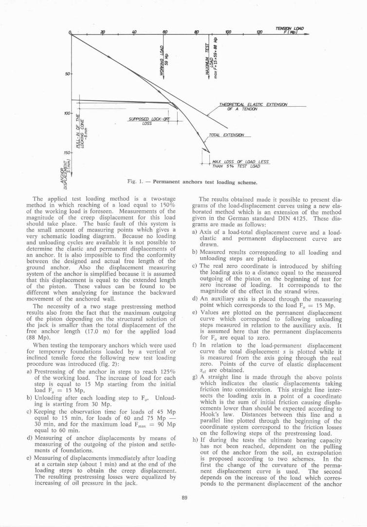
Loading tests of the permanent anchors by a forceof 88 Mp were performed in a simple way in thefollowing stages (fig. 1):
a) Prestressing of the anchor to 60 Mp with simultaneously measuring of the jack ram extension.
b) Locking-off the loading force through loosening ofthe jack. The moving back wire strands placed inthe anchor" block of the VSL system pull thegripping wedges and block the pulling system.
88
c) Moving back of the piston and further prestressingto 88 Mp. The piston, when moving, is pulling outthe strand wires together with the stressing head.Measuring of piston displacement for the maximumload.
d) Measuring of prestressing losses one hour afterapplication of maximum force.
e) Releasing of prestressing load. The strand wh'estogether with the stressing head are moving back tothe bearing plate.
T. ELAST1C EXTENSION
0
t
•.~
~~...,J~
50 ~E
SlPPOSED LOCK-J.I ~LDSS l t-
OF A TENlXJN
150 DMAX WSS OF WAD LESSTHAN 5 % TEST LOAD
Fig. 1. - Permanent anchors test Ioading scheme.
li.
The applied test loading method is a two-stageInethod in which reaching of a load equal to 110%of the working load is foreseen. Measurements of themagnitud~ of the creep displacement for this loadshould take place. The basic fauIt of this system isthe small amount of measuring points which gives avery schematic loading diagram. Because no loadingand unloading cycles are available it is not possible todetermine the elastic and permanent displacements ofan anchor. It is also impossible to find the conformitybetween the designed and actual free length of theground anchor. Aiso the displacement measuringsystem of the anchor is simplified because it is assumedthat this displacement is equal to the extended lengthof the piston. T'hese values can be found to bedifferent when analyzing for instance the backwardmovement of the anchored wall.
The necessity of a two stage prestressing methodresults also from the fact that the maximum outgoingof the piston depending on the structural solution of .the jack is smaller than the total displacement· of thefree anchor length (17.0 m) for the .applied load(88 Mp).
When testing the temporary anchors which were usedfor temporary foundations loaded by a vertical orinclined tensile force the following new test loadingprocedure was introduced (fig. 2):
a) Prestressing of the anchor in steps to reach 125°iOof the working load. The increase of load for eachstep is equal to 15 Mp starting from the initialload Fo == 15 Mp,
b) Unloading' after each loading step to Fo. Unloading is starting from 30 Mp.
c) Keeping the observation time for loads of 45 Mpequal to 15 min, for loads of 60 and 75 Mp 30 min, and for the maximum load Fmax == 90 Mpequal to 60 min.
d) Measuring of anchoJ; displacements by means ofmeasuring of the outgoing of the piston and settlements of foundations.
e) Measuring of displacements immediately after loadingat a certain step (about 1 min) and at the end of theloading steps to obtain the creep displacement.The resulting prestressing losses were equalized byincreasing of oil pressure in the jack.
The results obtained made it possible to present diagrams of the load-displacement curves using a new elaborated method which is an extension of the methodgiven in the German standard DIN 4125. These diagrams are made as follows:a) Axis of a load-total displacement curve and a load
elastic and permanent displacement curve aredrawn.
b) Measured results corresponding to all loading andunloading steps are plotted.
c) The real zero coordinate is introduced by shiftingthe loading axis to a distance equal to the measuredoutgoing of the piston on the beginning of test forzero increase of loading. .. 1t corresponds to themagnitude of the effect in the strand wires.-
d) An auxiliary axis is placed through the measuringpoint which corresponds to the load Fo == 15 Mp.
e) Values are plotted on the permanent displacementcurve which correspond to following unloadingsteps measured in relation to the auxiliary axis. Itis assumed here that the permanent displacementsfor Fo are equal to zero.
f) In relation to the load-permanent displacementcurve the total displacement S is plotted while itis measured from the axis going through. the realzero. Points of the curve of elastic displacementSel are obtained.
g) A straight line is made through the above points 'which indicates the elastic displacements takingfriction into consideration. This straight line intersects the loading axis. in a point of a coordinatewhich is the sum of initial friction causing displacements lower than should be expected according toHook's law. Distances between this line and aparallel line plotted through the beginning of thecoordinate system correspond to the friction losseson the following steps of the prestressing load.
h) If during the tests the ultimate bearing capacityhas· not been reached, dependent on the pullingout of the anchor from the soil, an extrapolationis proposed according to two schemes. In thefirst the change of the curvature of the permanent displacement curve is used. The seconddepends on the increase of the load which corresponds to the permanent displacement of the anchor
89
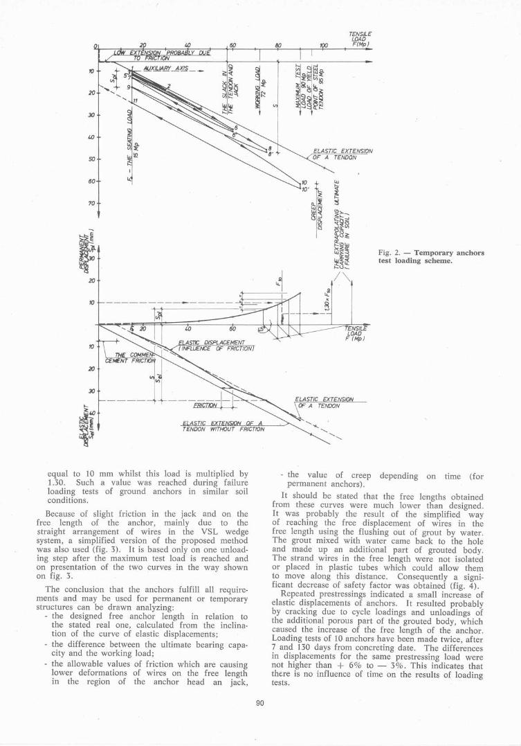
Fig. 2. - Temporary anchorstest loading scheme.
TENSILELDAD
F fMp}
ELA5T/C EXTENSIONOF A TENDON
ELAST/C EXTENSION
:::. A TENDON
........... ''*-..
"'-...........
...........
88'
TENSILELOAD
80 FfMp}
10
~
~
li)
70
20
10
20
10
30
equal to 10 mm whilst this load is multiplied by1.30. Such a value was reached during failureloading tests of ground anchors in similar soilconditions.
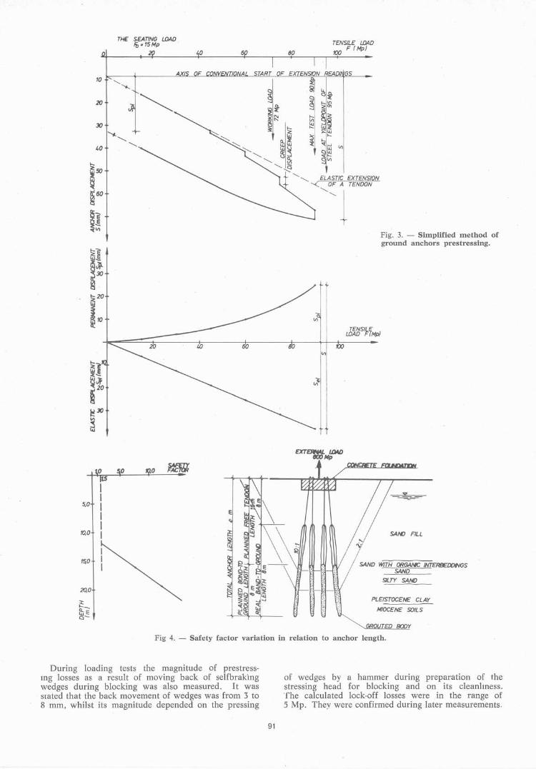
Because of slight friction in the jack and on thefree length of the anchor, mainly due to thestraight arrangement of wires in the VSL wedgesystem, a simplified version of the proposed methodwas also used (fig. 3). 1t is based only on one unloading step after the maximum test load. is reached andon presentation of the two curves in the way shownon fig. 3.
The conclusion that the anchors fulfill an requirements and may be used for permanent or temporarystructures can be drawn analyzing:
- the designed free .anchor length in relation tothe stated real one, calculated from the inclination of thecurve of elastic. displacements;
- the diffèrence between the ultimate bearing capacity and the working load;
- the allowable values of friction which are causinglower deformations of wires on the free lengthin the region of the anchor head an jack,
- the value of creep depending on time (forpermanent anchors).
1t should be stated that the free lengths obtainedfrom these curves were much lower than designed.1t was probably the result of the simplified wayof reaching the free displacement of wires in thefree length· using the flushing out of grout by water.The grout mixed with water came back to the holeand made up an additional part of grouted body.The strand wires in the free length were not isolatedor placed in plastic tubes which could allow themto move along this distance. Consequently a significant decrease of safety factor was obtained (fig. 4).
Repeated. prestressings indicated a small increase ofelastic displacements of anchors. 1t resulted probablyby cracking due to cycle loadings and unloadings ofthe additional porous part of the grouted body, whichcaused the increase of the free length of the anchor ..Loading tests of 10 anchors have been made twice, after7 and 130 days .fron1 concreting date. The differencesin displacements for the same prestressing load werenot higher than + 6% to - 3 °10. This indicates thatthere is no influence of time on the results of loadingtests.
90
10
20
30
THE SEATING LDADFb =15Mp TENSILE LOAD
100 F (Mp)
Fig. 3. - Simplified method ofground anchors prestressing.
TENSILéLOAD F(Mp)
5,0
tQO
1!iO
20,0
o
EXTERNAL IJJAD«XJNp
v
SAM) FILL
SAND W!TH ORGANe INTFRBEDDIVGSSAND
SlLTY SAND
PLEISTOCENE CLAY
MIDCENE SOILS
GROUTED BODY
Fig 4. - SaIety factor variation in relation to anchor length.
During loading tests the magnitude of prestressing lasses as a result of moving back of selfbrakingwedges during blocking was also measured. It wassrated that the back movement of wedges was from 3 ta8 mm, whilst its magnitude depended on the pressing
91
of wedges by a hammer during preparation of thestressing head for blocking and on its cleanhness.'fhe calculated lock-off lasses were in the range of5 Mp. They were confirmed during later measurements,