
Contribution of new technologies and methods for 3D land ... · interpretation of 2D seismic data....
4
Contribution of new technologies and methods for 3D land seismic acquisition and processing applied to reservoir structure enhancement – Block 10, Yemen Marc Girard*, TOTALFINAELF, Fabienne Pradalié, Jean Jacques Postel, CGG Summary The need to optimise the development of a marginal field in Yemen, in an awkward topographical environment, led to a 3D acquisition/processing operation being recommended in 2000, to be conducted in an extremely short timeframe and with tight budget constraints. The main objectives of the new 3D survey were to: • Reduce structural uncertainties at the top of the reservoir, • Reach a global improvement in the original 2D image, not only for the main reservoir, but also at deeper levels, down to the basement, • Help position and pilot future drilling. After a feasibility study, combined work on behalf of the operator and the contractor both in the field and during data processing led to optimised results, in terms of both quality and planning, without exceeding the total budget approved by the partners, and without any impact on the environment or accidents. The success of this operation was mainly due to: • Close co-operation between the Operator and Contractor throughout their joint efforts, with experienced supervisory personnel being mobilised for both acquisition and processing, • The innovative approach adopted both in the field (first use of the Sercel 408UL recorder in heliborne 3D production) and for the processing sequence (3D FK filtering and Pre Stack Time Migration on a routine basis). Introduction Block 10, operated by TOTALFINAELF E&P Yemen, in partnership with KUFPEC, SOCO and OXY, produces an average of 28,000 b/day mainly from its two fields, KHARIR and ATUF. Production started in 1997, on the KHARIR field, with the support of a tight 2D seismic grid (vibroseismic or explosive source, depending on the surveys). Block 10 is located on a limestone plateau, at a mean altitude of 1,000 m. It is heavily cut through by a very dense network of canyons (“wadis”) whose depth may reach 300 m. Surface conditions are variable on the plateau, meaning that while areas remote from the canyons have well consolidated terrain that transmits the seismic signal fairly correctly, the parts on the edges of the ravines are heavily eroded and consist of karst, generating very high energy ground roll and back scattered noise. On the KHARIR field, the main reservoir is located in the Upper Biyad sandstone formation dating from the Lower Cretaceous. Its average thickness is a hundred metres, for an oil column varying from 60 to 70 m. Reservoir depth, in relation to the datum (950 m), is about 1700 to 1800 m, corresponding to 1100 ms TWT on the seismic data. This is therefore a very shallow target. During the first two drilling phases, several well results (including some horizontal ones) highlighted the lack of accuracy of the depth maps, which were based on interpretation of 2D seismic data. Indeed, the quality of this data was limited due to several factors such as the only partial resolution of the problem of static corrections, a mixing of traces that filters discontinuities (making fault picking tricky) and an unfavourable signal/noise ratio, considering the already mentioned surface conditions. Feasibility study The main objectives of the feasibility study conducted on the KHARIR area were to: • Determine land parameters for 3D acquisition, optimised in terms of imagery for Biyad level, and if possible down to the underlying basement, • Choose a 3D geometry that would minimise the surface grid footprints after DMO, • Investigate operational aspects, especially the choice of source to be used (vibrators, dynamite or combination), • Recommend a standard processing sequence, • Simulate acquisition and processing costs. During the two first phases of the study, it was mainly through an analysis of existing 2D seismic data that we were able to draw up a first set of parameters. The study thus started with re-processing of a correctly sampled seismic line, followed by field reconnaissance. The choice of final 3D geometry requires the use of the SIM3D internal software, whose principle is summarized in Figure 1. SEG International Exposition and 72nd Annual Meeting Main Menu
Transcript of Contribution of new technologies and methods for 3D land ... · interpretation of 2D seismic data....

Contribution of new technologies and methods for 3D land seismic acquisition and processing applied to reservoir structure enhancement – Block 10, Yemen Marc Girard*, TOTALFINAELF, Fabienne Pradalié, Jean Jacques Postel, CGG Summary The need to optimise the development of a marginal field in Yemen, in an awkward topographical environment, led to a 3D acquisition/processing operation being recommended in 2000, to be conducted in an extremely short timeframe and with tight budget constraints. The main objectives of the new 3D survey were to: • Reduce structural uncertainties at the top of the
reservoir, • Reach a global improvement in the original 2D image,
not only for the main reservoir, but also at deeper levels, down to the basement,
• Help position and pilot future drilling. After a feasibility study, combined work on behalf of the operator and the contractor both in the field and during data processing led to optimised results, in terms of both quality and planning, without exceeding the total budget approved by the partners, and without any impact on the environment or accidents. The success of this operation was mainly due to: • Close co-operation between the Operator and
Contractor throughout their joint efforts, with experienced supervisory personnel being mobilised for both acquisition and processing,
• The innovative approach adopted both in the field (first use of the Sercel 408UL recorder in heliborne 3D production) and for the processing sequence (3D FK filtering and Pre Stack Time Migration on a routine basis).
Introduction Block 10, operated by TOTALFINAELF E&P Yemen, in partnership with KUFPEC, SOCO and OXY, produces an average of 28,000 b/day mainly from its two fields, KHARIR and ATUF. Production started in 1997, on the KHARIR field, with the support of a tight 2D seismic grid (vibroseismic or explosive source, depending on the surveys). Block 10 is located on a limestone plateau, at a mean altitude of 1,000 m. It is heavily cut through by a very dense network of canyons (“wadis”) whose depth may reach 300 m. Surface conditions are variable on the plateau, meaning that while areas remote from the canyons have well consolidated terrain that transmits the seismic signal fairly correctly, the parts on the edges of the ravines are heavily eroded and consist of karst, generating very high energy ground roll and back scattered noise.
On the KHARIR field, the main reservoir is located in the Upper Biyad sandstone formation dating from the Lower Cretaceous. Its average thickness is a hundred metres, for an oil column varying from 60 to 70 m. Reservoir depth, in relation to the datum (950 m), is about 1700 to 1800 m, corresponding to 1100 ms TWT on the seismic data. This is therefore a very shallow target. During the first two drilling phases, several well results (including some horizontal ones) highlighted the lack of accuracy of the depth maps, which were based on interpretation of 2D seismic data. Indeed, the quality of this data was limited due to several factors such as the only partial resolution of the problem of static corrections, a mixing of traces that filters discontinuities (making fault picking tricky) and an unfavourable signal/noise ratio, considering the already mentioned surface conditions. Feasibility study The main objectives of the feasibility study conducted on the KHARIR area were to: • Determine land parameters for 3D acquisition,
optimised in terms of imagery for Biyad level, and if possible down to the underlying basement,
• Choose a 3D geometry that would minimise the surface grid footprints after DMO,
• Investigate operational aspects, especially the choice of source to be used (vibrators, dynamite or combination),
• Recommend a standard processing sequence, • Simulate acquisition and processing costs. During the two first phases of the study, it was mainly through an analysis of existing 2D seismic data that we were able to draw up a first set of parameters. The study thus started with re-processing of a correctly sampled seismic line, followed by field reconnaissance. The choice of final 3D geometry requires the use of the SIM3D internal software, whose principle is summarized in Figure 1.
SEG International Exposition and 72nd Annual Meeting Main Menu
Contribution of new technologies and methods for 3D land seismic acquisition and processing applied to reservoir structure enhancement – Block 10, Yemen
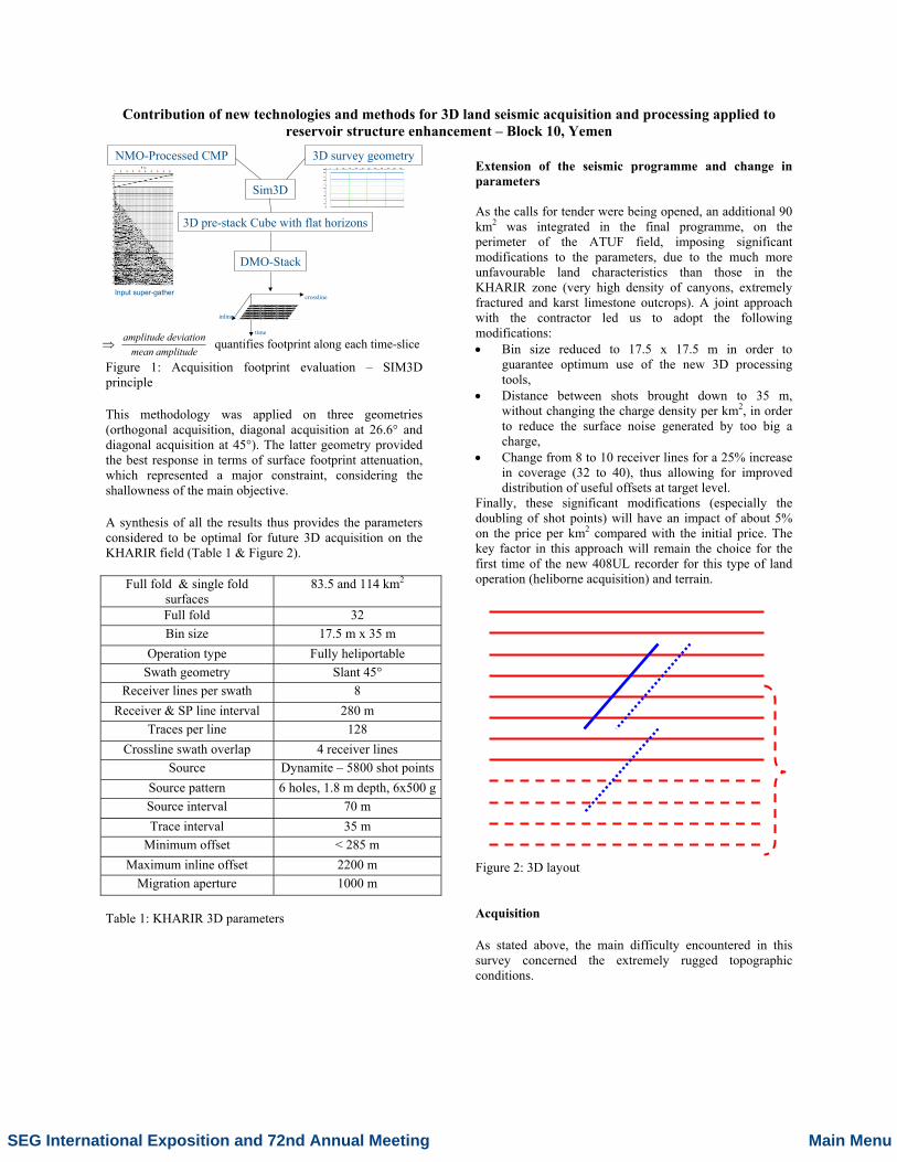
amplitudemeandeviationamplitude
⇒ quantifies footprint along each time-slice
NMO-Processed CMP 3D survey geometry
Sim3D
3D pre-stack Cube with flat horizons
DMO-Stack
time
crossline
inline
Input super-gather
Figure 1: Acquisition footprint evaluation – SIM3D principle This methodology was applied on three geometries (orthogonal acquisition, diagonal acquisition at 26.6° and diagonal acquisition at 45°). The latter geometry provided the best response in terms of surface footprint attenuation, which represented a major constraint, considering the shallowness of the main objective. A synthesis of all the results thus provides the parameters considered to be optimal for future 3D acquisition on the KHARIR field (Table 1 & Figure 2).
Full fold & single fold surfaces
83.5 and 114 km2
Full fold 32 Bin size 17.5 m x 35 m
Operation type Fully heliportable Swath geometry Slant 45°
Receiver lines per swath 8 Receiver & SP line interval 280 m
Traces per line 128 Crossline swath overlap 4 receiver lines
Source Dynamite – 5800 shot points Source pattern 6 holes, 1.8 m depth, 6x500 gSource interval 70 m Trace interval 35 m
Minimum offset < 285 m Maximum inline offset 2200 m
Migration aperture 1000 m Table 1: KHARIR 3D parameters
Extension of the seismic programme and change in parameters As the calls for tender were being opened, an additional 90 km2 was integrated in the final programme, on the perimeter of the ATUF field, imposing significant modifications to the parameters, due to the much more unfavourable land characteristics than those in the KHARIR zone (very high density of canyons, extremely fractured and karst limestone outcrops). A joint approach with the contractor led us to adopt the following modifications: • Bin size reduced to 17.5 x 17.5 m in order to
guarantee optimum use of the new 3D processing tools,
• Distance between shots brought down to 35 m, without changing the charge density per km2, in order to reduce the surface noise generated by too big a charge,
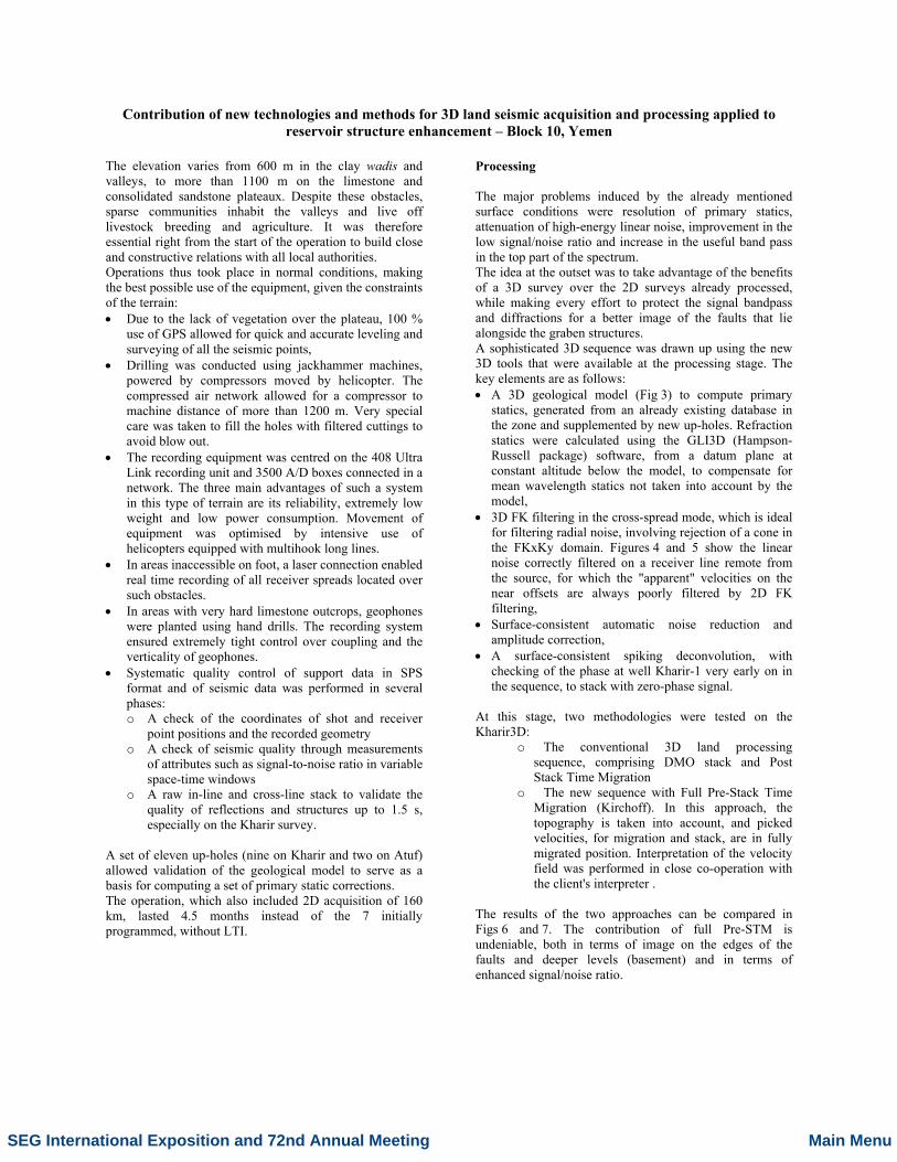
• Change from 8 to 10 receiver lines for a 25% increase in coverage (32 to 40), thus allowing for improved distribution of useful offsets at target level.
Finally, these significant modifications (especially the doubling of shot points) will have an impact of about 5% on the price per km2 compared with the initial price. The key factor in this approach will remain the choice for the first time of the new 408UL recorder for this type of land operation (heliborne acquisition) and terrain. Figure 2: 3D layout Acquisition As stated above, the main difficulty encountered in this survey concerned the extremely rugged topographic conditions.
SEG International Exposition and 72nd Annual Meeting Main Menu
Contribution of new technologies and methods for 3D land seismic acquisition and processing applied to reservoir structure enhancement – Block 10, Yemen
The elevation varies from 600 m in the clay wadis and valleys, to more than 1100 m on the limestone and consolidated sandstone plateaux. Despite these obstacles, sparse communities inhabit the valleys and live off livestock breeding and agriculture. It was therefore essential right from the start of the operation to build close and constructive relations with all local authorities. Operations thus took place in normal conditions, making the best possible use of the equipment, given the constraints of the terrain: • Due to the lack of vegetation over the plateau, 100 %
use of GPS allowed for quick and accurate leveling and surveying of all the seismic points,
• Drilling was conducted using jackhammer machines, powered by compressors moved by helicopter. The compressed air network allowed for a compressor to machine distance of more than 1200 m. Very special care was taken to fill the holes with filtered cuttings to avoid blow out.
• The recording equipment was centred on the 408 Ultra Link recording unit and 3500 A/D boxes connected in a network. The three main advantages of such a system in this type of terrain are its reliability, extremely low weight and low power consumption. Movement of equipment was optimised by intensive use of helicopters equipped with multihook long lines.
• In areas inaccessible on foot, a laser connection enabled real time recording of all receiver spreads located over such obstacles.
• In areas with very hard limestone outcrops, geophones were planted using hand drills. The recording system ensured extremely tight control over coupling and the verticality of geophones.
• Systematic quality control of support data in SPS format and of seismic data was performed in several phases: o A check of the coordinates of shot and receiver
point positions and the recorded geometry o A check of seismic quality through measurements
of attributes such as signal-to-noise ratio in variable space-time windows
o A raw in-line and cross-line stack to validate the quality of reflections and structures up to 1.5 s, especially on the Kharir survey.
A set of eleven up-holes (nine on Kharir and two on Atuf) allowed validation of the geological model to serve as a basis for computing a set of primary static corrections. The operation, which also included 2D acquisition of 160 km, lasted 4.5 months instead of the 7 initially programmed, without LTI.
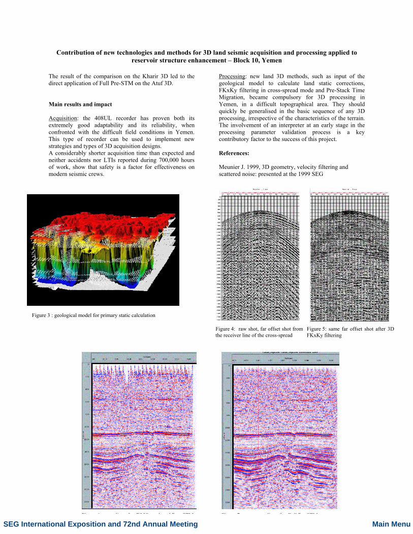
Processing The major problems induced by the already mentioned surface conditions were resolution of primary statics, attenuation of high-energy linear noise, improvement in the low signal/noise ratio and increase in the useful band pass in the top part of the spectrum. The idea at the outset was to take advantage of the benefits of a 3D survey over the 2D surveys already processed, while making every effort to protect the signal bandpass and diffractions for a better image of the faults that lie alongside the graben structures. A sophisticated 3D sequence was drawn up using the new 3D tools that were available at the processing stage. The key elements are as follows: • A 3D geological model (Fig 3) to compute primary
statics, generated from an already existing database in the zone and supplemented by new up-holes. Refraction statics were calculated using the GLI3D (Hampson-Russell package) software, from a datum plane at constant altitude below the model, to compensate for mean wavelength statics not taken into account by the model,
• 3D FK filtering in the cross-spread mode, which is ideal for filtering radial noise, involving rejection of a cone in the FKxKy domain. Figures 4 and 5 show the linear noise correctly filtered on a receiver line remote from the source, for which the "apparent" velocities on the near offsets are always poorly filtered by 2D FK filtering,
• Surface-consistent automatic noise reduction and amplitude correction,
• A surface-consistent spiking deconvolution, with checking of the phase at well Kharir-1 very early on in the sequence, to stack with zero-phase signal.
At this stage, two methodologies were tested on the Kharir3D:
o The conventional 3D land processing sequence, comprising DMO stack and Post Stack Time Migration
o The new sequence with Full Pre-Stack Time Migration (Kirchoff). In this approach, the topography is taken into account, and picked velocities, for migration and stack, are in fully migrated position. Interpretation of the velocity field was performed in close co-operation with the client's interpreter .
The results of the two approaches can be compared in Figs 6 and 7. The contribution of full Pre-STM is undeniable, both in terms of image on the edges of the faults and deeper levels (basement) and in terms of enhanced signal/noise ratio.
SEG International Exposition and 72nd Annual Meeting Main Menu
Contribution of new technologies and methods for 3D land seismic acquisition and processing applied to reservoir structure enhancement – Block 10, Yemen
The result of the comparison on the Kharir 3D led to the direct application of Full Pre-STM on the Atuf 3D. Main results and impact Acquisition: the 408UL recorder has proven both its extremely good adaptability and its reliability, when confronted with the difficult field conditions in Yemen. This type of recorder can be used to implement new strategies and types of 3D acquisition designs. A considerably shorter acquisition time than expected and neither accidents nor LTIs reported during 700,000 hours of work, show that safety is a factor for effectiveness on modern seismic crews.
Processing: new land 3D methods, such as input of the geological model to calculate land static corrections, FKxKy filtering in cross-spread mode and Pre-Stack Time Migration, became compulsory for 3D processing in Yemen, in a difficult topographical area. They should quickly be generalised in the basic sequence of any 3D processing, irrespective of the characteristics of the terrain. The involvement of an interpreter at an early stage in the processing parameter validation process is a key contributory factor to the success of this project. References: Meunier J. 1999, 3D geometry, velocity filtering and scattered noise: presented at the 1999 SEG
Figure 4: raw shot, far offset shot from the receiver line of the cross-spread
Figure 5: same far offset shot after 3D FKxKy filtering
Figure 3 : geological model for primary static calculation
Figure 6: cross-line after DMO stack and Post STM Figure 7: same cross line after Full Pre STM
SEG International Exposition and 72nd Annual Meeting Main Menu