Continuously Variable Transmission-Assessment of ... · PDF fileContinuously Variable ......
33
- --- -- L 1 \ 11 \ 11111 \ 111 \ II \\11 11 \111 \111 \1\ \ II 11 \\ 11 \11 \ II \11\ 111\\\ II I 1\ 3 1176 00166 1835 .. DOE/NASA/51 044-23 e NASA TM-82700 NASA-TM-82700 19810024941 Continuously Variable Transmission-Assessment of Applicability to Advanced Electric Vehicles Stuart H. Loewenthal and Richard J. Parker National Aeronautics and Space Administration Lewis Research Center Work performed for U.S. DEPARTMENT OF ENERGY Conservation and Renewable Energy Office of Vehicle and Engine R&D Prepared for Electric Vehicle Council Symposium VI Baltimore, Maryland, October 21 - 23 , 1981 LIBRARY COpy OCT 2 9 1981 LANGLEY R"S 7/\R.- , : £NTER UBP..t.RY, NASA HAMPTON, VIRGINIA https://ntrs.nasa.gov/search.jsp?R=19810024941 2018-05-20T12:36:18+00:00Z
Transcript of Continuously Variable Transmission-Assessment of ... · PDF fileContinuously Variable ......

- - - - - -
L
1\ 11\ 11111\ 111\ II \\11 11\111 \111 \1\\ II 11\\ 11\11\ II \11\ 111\\\ II I 1\ 3 1176 00166 1835
..
DOE/NASA/51 044-23 e NASA TM-82700 NASA-TM-82700 198 10024941
Continuously Variable Transmission-Assessment of Applicability to Advanced Electric Vehicles
Stuart H. Loewenthal and Richard J. Parker National Aeronautics and Space Administration Lewis Research Center
Work performed for U.S. DEPARTMENT OF ENERGY Conservation and Renewable Energy Office of Vehicle and Engine R&D
Prepared for Electric Vehicle Council Symposium VI Baltimore, Maryland, October 21 - 23, 1981
LIBRARY COpy OCT 2 9 1981
LANGLEY R"S 7/\R.- , : £NTER UBP..t.RY, NASA
HAMPTON, VIRGINIA
https://ntrs.nasa.gov/search.jsp?R=19810024941 2018-05-20T12:36:18+00:00Z

\ \
~, • I
" I
NOTICE
This report was prepared to document work sponsored by I
the United StateS Government. Neither the United States nor its agent, the united States Department of Energy, nor any Federal employees, nor any of their contractors, subcontractors or their employees, makes any warranty, express or implied, or assumes any legal liability or responsibility for the accuracy, completeness, or usefulness of any information, apparatus, product or process disclosed, or represents that its use woul~ not infringe privately owned rights.
~.

,F-
Continuously Variabl~ Transmission-As'sessment of Applicability to Advanced Electric Vehicles
Stuart H. Loewenthal and Richard J. Parker National Aeronautics and Space Administration Lewis Research Center Cleveland, Ohio 44135
Work performed for U.S. DEPARTMENT OF ENERGY Conservation and Renewable Energy Office of Vehicle and Engine R&D Washington, D.C. 20545
DOE/NASA/51 044-23 NASA TM-82700
;. . Under Interagency Agreement DE-AI04-77CS51 044
Electric Vehicle Council Symposium VI Baltimore, Maryland, October 21-23, 1981
~.
t/<l1-J.3 $I ~~

CONTINUOUSLY VARIABLE TRANSMISSION - ASSESSMENT OF
APPLICABILITY TO ADVANCED ELECTRIC VEHICLES
by Stuart H. Loewenthal and Richard J. Parker
National Aeronautics and Space Administration Lewis Research Center
Cleveland, Ohio 44135
ABSTRACT
A brief historical account of the evolution of continuously variable transmissions- (CVT) for automotive use is given. CVT concepts which are potentially suitable for application with electric and hybrid vehicles are discussed. The arrangement and function of several CVT concepts are cited
'along with their current developmental status. The results of preliminary design studies conducted under contract to NASA for DOE on four CVT concepts for use in advanced electric vehicles are discussed. For these studie~ a 1700 kg (3750 Ib) vehicle with an energy storage flywheel was specified. Requirements of the CVTs were a maximum torque of 450 N-m (330 lb-ft), a
~ maximum output power of 75 kW (100 hp), and a flywheel speed range of 14 000 ~ to 28 000 rpm. System life was to exceed 2600 hours at a 90-percent proba-W bility of survival. Efficiency, size, weight, cost, reliability, maintain
ability, and controls were evaluated for each of the four concepts. The design studies were performed by Garrett/AiResearch (torodial traction CVT), Battelle Columbus Labs (steel V-belt CVT), Kumm Industries (flat belt variable diameter pulley CVT) , and Bales-McCoin Tractionmatic (cone-roller traction CVI). All CVTs exhibited relatively high calculated efficiencies (86 to 97 percent) over a broad range of vehicle operating conditions. Esti~ated weight and size of these transmissions were comparable to or les~ than an equivalent automatic transmission.
INTRODUCTION
The range of an electric vehicle is primarily dependent on the energy capacity of the batteries and the rate at which power is withdrawn. Electric vehicles have been constructed without multi-speed transmissions but the lack of torque multiplication that the transmission affords results in high current drains on the batteries during starting, passing and hill climbing. High discharge currents not only adversely affect battery capacity and life but, moreover, require the use of unnecessa~ily large motors and more costly controls. Furthermore, using only voltage 'control with a D.C. motor results in less efficient motor operation over the vehicle's driving cycle than that attainable with a variable speed transmission. In a recent propulsion system design study (ref. 1). The addition of a multiratio transmission significantly reduced propulsion system weight and lessened its cost for an electric vehicle powered by a DC shunt motor with field'control. Incorporating a continuously variable transmission (CVT) and flywheel energy storage device into this system resulted in the lightest of the 17 configurations investigated and the fourth least expensive (ref. 1).

, ,"
Although CVTs offer potential p~rformance advantages, the bulk of transmissions currently used in electric vehicle are either one speed (direct coupled) or discrete multispeed units (ref. 2). Host of the multispeed units are small passenger car transmissions. In the case of cars converted to run on electrical power, existing transmissions are usually left in place. In most cases, the size and speed ratios of these transmissions are not well matched to the operating characteristics of the electric motor and vehicle.
The limited use of CVTs in passenger cars has hindered their application to electric vehicles. As will be discussed, CVTs were quite popular with designers of early automobiles but this popularity was relatively short lived. Improvements in the shifting characteristics of manual gearboxes in the late 1920's lessened the incentive to develop improved continuously variable transmissions. Through the years there have been occasional attempts, both here and in Europe, to commercially introduce CVTs into passenger cars. Several of these efforts proved technically feasible, but they were never really serious contenders to replace the automatic, torqueconvertor, gear-shift transmission which was introduced in the early 1940's. Up until the 1970's, the primary emphasis for automatic transmissions was on transmission shift quality and cost while efficiency was basically a secondary consideration. In recent years the emphasis has changed to improving passenger car fuel economy by improving drive train efficiency. The shortage of petroleum has also stimulated research on alternate types of automotive powerplants, such as electric and gas turbine. Onboard flywheel energy storage devices are also being investigated as a means of improving fuel economy. These factors, in turn, have triggered renewed CVT activity. The eVT's "infinite" number of shift points offers the engine designer the greatest possible latitude in optimizing his drive train, no matter what the powerplant.
It is the intent of this paper to review some of the ~ast and more recent CVT development activities, particularly those which are potentially suitable for electric and hybrid vehicle applications. A second objective is to review the results of preliminary design studies that have been recently conducted on four CVT concepts for use with a flywheel equipped electric vehicle.
Past Automotive CVTs
Although the potential performance benefits associated with a continously variable transmission for various types of machinery had been recognized at an early date, it wasn't until the-introduction of the horseless carriage at the end of the nineteenth century that the goa~ of developing a CVT took on real meaning. It quickly became apparent to the designers of early automobiles that a highly flexible transmission was badly needed to compensate for the lack of flexibility of "the early gasoline engines. These engines had a tendency to run well at only one speed. As noted by P. M. Heldt in an unusually comprehensive review of the development of the automatic transmission (ref. 3), the chief objection to early sliding-gea~ transmission, apart from their lack of flexibility was the difficulty in gear shifting. The gearboxes used on many of the early vintage cars, such as 1890 Panhard, were adopted from the clash gears used in factory equipment
2

(ref. 4). Gear changing was not merely difficult but potentially damaging to the gear teeth. According'to Hodgesafld'Wise (ref. 5), "the best technique with those early cars was to slip the clutch gently and bang the gears home as quickly as possible, in the hope that you might catch the cogs unawares." {Although Prentice and Shiels patented the syn~hromesh principle back in 1904, it wasn't until the late nineteen twenties that General Motors perfected the syncromesh gearshift for production which allowed almost any driver to shift from one speed to the next without clashing the gears (ref. 6». In view of the limitations and inconveniences associated with gear changing, it is not surprising that the inventors of the day looked for a simple means of continuously and, hopefully, automatically varying the speed ratio between the engine and the wheels. '
Mechanical ratchet, hydraulic and electro-mechanical drives were tried but drives using friction power transfer were the first mass-produced automobile transmissions to provide continuous ratio selection. The earliest of these were rubber V-belt drives appearing on the 1886 Benz and Daimler cars, the first mass-produced gasoline engine powered vehicles. Friction disk drives, similar in construction to the Gearless Transmission as illustrated in a 1906 advertisement shown in figure 1 (ref. 7) were used as regular equipment on a number of early motor cars. These included the 1906 Cartercar, ,1907 Lambert, 1909 Sears Motor Buggy and 1914 Metz Speedster. An early advertisement for the Lambert appears in figure 2.
The Cartercar, pictured in figure 3, ,had an extremely simple friction drive consisting of a metal'disk driven by the engine crankshaft which was in traction contact with a large, fiber-covered spoked wheel mounted on a transverse countershaft. The countershaft, in turn, was connected to the rear axle by an ordinary chain drive. To vary speed ratio, a driver operated lever (see fig. 3) was used to radially position the output follower wheel across the face of the metal disk; turntable fashion. Neutral was achieved when the follower wheel was centered. By moving the follower wheel past center, reverse rotation would occur to allow the vehicle to back up. The smoothness and ease of operation of the Cartercar transmission made it quite popular. It is not well known that Mr. W. C. Durant, founder and first president of General Motors Company, acquired the Cartercar Company in 1908 because of his expectation that friction drives would soon be universally used in automobiles (refs. 6 and 8).
From 1909 until 1912, Sears marketed a two-cylinder, l4-horsepower '''Motor Buggy," also equipped with a friction drive (ref. 9). "Absolutely simplicity, its positiveness under the most severe conditions and its unequalled flexibility," boasted one of the Sear's ads. However, by about 1915, cars equipped with friction drives had virtually disappeared (ref. 9), presumably due, in part, to the need to frequently renew the friction
" material. Despite the limited success of these earlier attempts, the goal of
designing an automotive transmission that smoothly and automatically shifted was not lost. In the late 1920's, the Buick Division of General Motors was given the task of developing a continuously variable, oil lubricated, steelon-steel traction drive. This transmission was similar in design to the Hayes double toroidal traction drive,patented in 1929. The Hayes SelfSelector Transmission (ref. 10), although originally developed in the U.S., was later offered as an option on the 1935 British Austin Sixteen (ref. 11).
3

The geometry of the G.M. toroidal drive, later called the Toric transmission, is remarkably similar to the 1877 Hunt drive with the addition of a second toroidal cavity and a ball differential to balance loading between the two cavities. An extensive test program was conducted on this drive. Seventeen road test vehicles equipped with the Toric drive accumulated over 300 000 miles of road testing (ref. 8). A 20 percent improvement in highway fuel mileage was reported. In 1932, G.M. made the decision to produce this type of transmission (ref. 6). However, no cars equipped with the Toric drive were ever sold to the public. The reasons for halting production were never really made clear. Some say that there were unresolved discrepancies in service life data obtained during road tests and that obtained from laboratory bench ~esters. Others believe that the availability of premium quality bearing steel which was needed in large amounts to make each drive was simply not great enough at the time to meet expected production requirements. Whatever the reasons, Alfred P. Sloan, Jr., then president of G.M., turned the transmission down for production with the belief that it would simply be too e~pensive to make (ref. 6).
Work on various types of automatic transmissions, beginning in the early 1920's finally lead to the production of the 1937 Oldsmobile semiautomatic, self-shifting transmission. This transmission still required the use of a clutch ped~l for stopping and starting. The Hydra-matic, torque converter automatic shifting gearbox soon followed. It was the first massproduced, fully automatic transmission, and appeared first on the 1940 Oldsmobile (ref. 6). This transmission was the predessor of the modern automatic transmission used in virtually all of today's cars.
Transmission Requirements for an Electric Vehicle
In any vehicle, the role of the transmission is to efficiently match the operating character~stics of the power plant to that of the vehicle. Low cost, long life, small size, low weight and smoothness of operation are also sought after. In the case of electric vehicles, transmission noise can be particularly offensive, since the usual background noise of the engine is virtually absent. Electric vehicles tend to be heavier than cars with internal combustion engines due to battery and motor weight. Also electric motors for these vehicles have significantly less available power. Consequently transmissions for electric vehicles tend to spend more time at high reduction ratios where there is more torque amplification available.
Motor characteristics. - DC series wound motors are used on the majority of electric vehicles because of their favorable operating characteristics and their availability (ref. 2). Series motors tend to produce more torque per ampere than other types of electrical motors under heavy loads, thereby reducing battery drain during passing or hill climbing (ref. 2). The highest torques are produced at the lowest speeds where efficiency is relatively low as shown in figure 4. Thus using a multi-speed transmission to requce motor torque would have a beneficial effect on efficiency. The 400 ampere motor current limit line represents the maximum torque that the motor can safely generate. Efficiency appears to increase with power, suggesting that light duty operation such as low speed cruise would be relatively inefficient. Motor efficiency is relatively speed insensitive above about 2000 rpm. This suggests that the deviation from the best-motor-
~
4

efficiency-line 'that would result from using a'twoor three-speed trans-mission would compromise performance in a minor way. '
DC shunt wound motors, although not as popular as series type for electric vehicles, lend themselves to regenative braking and require significantly lower battery currents above base speed (ref. 2). Figure 5 shows the efficiency/speed characteristics of a typical D.C. shunt wound electric motor from a study performed in reference 1. It is clear from this figure that the D.C. shunt motor is most efficient between 40 to 70 percent of rated power. Like the series motor, efficiency of the shunt motor is relatively speed insensitive. In view of this relatively small efficiency spread a continuously variable transmission would not be an absolute necessity. However, other considerations such as transmission efficiency, ratio range, cost, or smoothness of operation might still justify the use of a CVT over a multi-shift gear transmission.
In the case of an A.C. induction motor, the efficiency is fairly flatrated with power, as shown in figure 6 from reference 1. Since A.C. lnachines do not have brushes, they can be operated at higher speeds than D.C. motors. This can result in a significantly smaller frame size for the A.C. motor (ref. 1). For the A.C. motor of figure 6, the rated speed is 26 500 rpm. However, to take advantage of this small size, a means must be found to regulate speed. One approach would be to use a CVT. A second approach would be to use variable frequency control, as illustrated in figure 7. The penalty for frequency control is the attendant complexity and cost of the inverter. Figure 7 from reference 1, shows that relatively high motor efficiency can be maintained at low power levels, provided that ~otor, speed can be kept at sufficiently high levels. Ideally, this could be accomplished witha CVT but a 2- or 3-speed gear box would probably suffice.
Hybr~~'!.~Q1.whe~!.~stems. - Adding a heat engine either in series or in parallel with an electric motor can increase the performance and range of the vehicle but at the expense of added complexity and cost. In a parallel arrangement, the electric drive can be the same as in an all-electric vehi-' ' cle but the transmission must accept power inputs from both the heat engine and the electric motor.
The operating efficiency of' most heat engines, i.e., spark-ignition, diesel or gas turbine, is sufficiently sensitive to engine speed as to significantly benefit from the use of a CVT. However, the extent that CVTs
'benefit fuel economy relative to advanced automatic transmissions for a car with a spark ignition engine is often a point of controversy (ref. 12). A recent Ford Motor Co. computer simulation showed a substantial 25 percent ,fuel mileage improvement using a CVT relative to an advanced 4-speed automatic transmission with torque converter lockup (ref. 13). This calculation was performed for a 1815 kg car over the metro driving cycle, using a conservative 82 percent efficiency for the CVT and correcting the fuel mileage for exhaust emissions. A test vehicle equipped with an Orshansky hydromechanical CVT demonstrated a 23 percent fuel economy improvement over the Federal composite driving cycle relative to the same vehicle with the production three-speed automatic transmission (ref. 14). These tests were conducted on a chassis dynamometer, and no adjustments for exhaust emissions were made. The above results lends support to the presumption that a CVT would be beneficial to a hydrid vehicle drive system because of the heat engine.
5

Flywheel energy storage can significantly improve the range, acceleration performance and battery life of an electric vehicle (refs. 15 to 17). Range and battery life are extended by the load leveling effect provided by the flywheel and by its ability to rapidly recover braking energy. With a flywheel, electric vehicle performance can be maintained over the life of the battery regardless of age or depth of discharge of the battery (ref. lS). Actual performance tests show that regenerative braking can increase the range of electric vehicles (ref. 2).
In the case of vehicles equipped with flywheels, some forms of CVT is needed to continuously regulate the speed, hence torque delivered by the flywheel to the vehicle and vice versa. Because of the quick discharge capability of the flywheel, acceleration performance of a flywheel electric vehicle can temporarily equal or exceed that of a heat engine vehicle. The ratio range requirements of a CVT for a flywheel vehicle is typically greater than a vehicle without a flywheel since the flywheel might be operating at some minimum speed while the vehicle is at some maximum speed and vice versa. This is more demanding on the CVT than a conventional vehi~ cle where the power plant itself has a wide speed range and where the speed of the power plant tends to increase with vehicle speed due to the greateF power required.
Advanced Vehicle CVT Applications
Within the last decade, there have been a number of attempts to reintroduce CVTs into passenger automobiles (refs. 2, 14, 19 and 20). Although these attempts have, thus, far, been largely unsuccessful from a commercial stand point, virtually all of the car Inakers have some amount of CVT assessment activity underway. Fiat, Volvo, British Leyland, Renault, and Volkswagen (refs. 21 to 25) are the most prominent in the field with active CVT development programs, while domestic car manufacturers are either quietly assessing the technology as it evolves or have seme low level, undisclosed CVT projects. The foreign car producers tend to place more emphasis on CVTs than we do, with gasoline 2 to 3 times more expensive than here and with a far smaller capital investment in the production of conventional automatic transmissions. u.s. auto manufacturers have been slowly upgrading the performance of some of their automatic transmission by adding an overdrive speed range, torque converter lockup or by splitting part of the power between the relatively inefficient torque converter and the mechanical gearing. Relatively modest (less than 10 percent) fuel mileage improvements have been realized overall with these improved transmissions (refs. 13 and 26). The largest economy gains are realized during highway driving when overdrive and the torque converter lockup features are being more heavily utilized.
Rubber V-belt CVTs. - Variable speed V-belt drives have been used on low power vehicles, such as snowmobiles, for many years. They appeared briefly on early automobiles at the turn of the century along with variable ratio friction drives. Their simplicity relative to other types of speed changers makes them attractive for automotive service where periodic belt replacement can be tolerated. The only automobile being Inass produced today that is equipped with a CVT has a rubber belt transmission. The car is the Volvo 343, a medium size sedan weighing about 900 kg (ref. 22). Its twin
6

, ~,'
rubber V-belt transmission, referred to as.the Variomatic, has a ratio range of 3.7 to 1 and transmits a maximum of 52 kW~ The design of this transmission is at least 20 years old. It was originally developed in Holland for use on the DAF 66, introduced in 1972. An improved, microprocessor con-
-~~rolled V-belt drive with a wider ratio range of 4.6 to 1 is being evaluated by Volvo. Their tests show about a 20 percent drop in fuel consumption
, during city driving relative to the 4-speed manual transmission test car. -At higher speeds there is little difference between the two systems.
Some of the Japanese can manufacturer are purportedly evaluating rubber V-belt drives for their small cars. In 1980, Fiat published a report (ref. 25) on tests conducted with a Fiat 127 equipped with an experimental, single rubber V-belt CVT having a 4.75 to I ratio range. The V-belt transmission gave approximately a 15 percent drop in fuel consumption relative to
-: the some type of test vehicle equipped with the production manual trans.mission. This is noteworthy, as reference 25 points out, because going from a manual to an automatic transmission generally increases fuel consumption by approximately 10 percent.
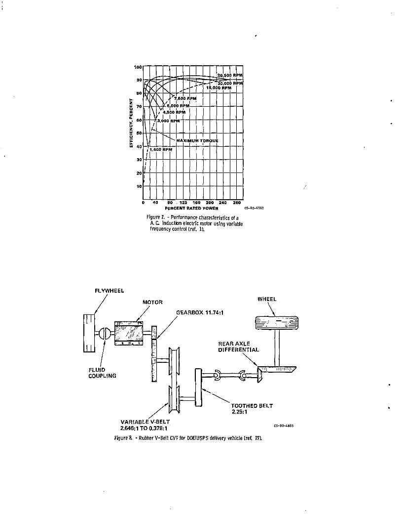
Rubber V-belt drives have also seen applied to electric vehicles. The Waterman OAF sedan, powered by a 6.7 kW DC series motor is one example (ref. 2). Another example is the flywheel-electric DOE/USPS postal vehicle. A schematic of the power train for this vehicle appears in figure 8 (ref. 27). A 36 OOO-rpm flywheel is working in tandem with an electric motor. The flywheel drives, through a reduction gear, a rubber V-belt drive with a 7-to-1 ratio range, to power the vehicle up to its 33 mph cruise speed. At speeds of 7 mph or less, the flywheel is decoup1ed from the vehicle by the fluid coupling, and the electric motor does all the driving.
In summary, for small, relatively low powered vehicles, the rubber· V-belt CVT offers the combination of relatively low cost and efficient operation. Average efficiencies in the low nineties can be expected. However durability-limitations hampers the application of these systems to larger vehicles. The OAF and Volvo approach of combing two V-belt drives in parallel raises acceptable power limits at the expense of added cost and complexity. Average service lives of 40 000 to 50 000 km for medium size vehicles are not unco~non. Improvements in the technology of rubber V-belt construction are continually being made, but current power limits, basically defined by the temperature limits of rubber, confine their current use to smaller systems such as small cars and snowmobiles.
Metal V-belt CVTs. - A promosing new entry to the automotive CVT race, is the compression, steel V-belt transmission. It is called a compression belt because the driver pulley "pushes" rather than "pulls" the driven pulley through a stack of V-shaped metal blocks. The principles of operation will be discussed in more detail later. The compression V-belt drive
i is produced by van Doorne Transmissie B.V. of the Netherlands (ref. 28) • . ' Recently, Borg-Warner and Fiat have joined van Doorne to form a consortium .~ to further the development of this concept and to prepare it for possible
production in cars or light trucks. Several test vehicles, including a fleet of Fiat test cars, have been retrofitted with the van Doorne transmission and have apparently shown acceptable operation. Reliability and endurance characteristics of this transmission as appiied t~ automobiles, although inherently higher than those of rubber V-belt drives, are still being established by Fiat's road test program.
7

Renualt reports (ref. 21) a 28 percent boost in fuel mileage with the van Doorne Transmatic transmission replacing the normal 4-speed manual gearbox in the ,Renault l4TL test car. Mechanical efficiencies of the Transmatic are reported to be somewhat better (ranging from 88 to 92 percent) than that of·a conventional automatic transmission. However Renault officials, according to a·recent (8/10/81) Automotive News article, are somewhat critical of this CVT because of "secondary noise problems and unusual acceleration characteristics" obtained during recent tests with an advanced, fuel efficient vehicle.
Chain-type CVTs. - Although variable speed chain drives are basically industrial in nature, they have been evaluated for car applications. One example is test program conducted by GKN Transmission Ltd in England. Tests were conducted on a front wheel drive car equipped with a continuously variable PIV variator made in West Germany. The PIV variator consists of a chain whose links are connected by smooth, round-ended pins which are trapped between two smooth faced, V-shaped pulley sheaves. Speed ratio is varied in the same manner as any other V-belt drive. In the GKN installation, the PIV varia tor is integrated with a ratio expanding, gear differential to provide control down to zero vehicle speed. Fuel economy improvements of up to 25 percent were realized. Based on projections, pin end wear would require that the chain be renewed approximately every 80 000 km on the average.
In reference 29, application of the PlV variator for both in-plant and highway vehicles is discussed. weight PlV varia tor was developed having efficiencies mately 85 to 90 percent over its 4 to 1 ratio range.
to electric vehicles A special, light ranging from approxi-
Hydraulic and hydromechanical CVTs. - Hydraulic variable speed ·.drives have a long history of use in vehicles. Hydrostatic (variable speed pump/motor) drives are used extensively in construction and off-the-road vehicles because of their durability and their ability to handle high alnounts of power in a small package size. Their relatively low efficiency and high noise makes them unsuitable for passenger carrying automobiles without the. addition of power-splitting mechanical gearing to minimize the power transmitted hydraulically. Hydromechanical (hydraulic plus mechanical) transmission have been investigated for car, truck and bus applications (refs. 14 and 30).
In the late 1970's, Orshansky Corp. demonstrated a 23 percent fuel economy improvement with their hydromechanical CVT relative to the stock 3 speed automatic test car (ref. 14). Israel's Scientific Research Foundation (SRF) purportedly (ref. 31) doubled the range of an ordinary electric powered van using a new nickel-zinc battery, a mechanical flywheel and a hydro-. mechanical CVT with a novel, rotating-case hydrostatic module.
Even with power-splitting gearing, hydromechanical units tend to be less efficient and considerably noiser than other types of CVTs. On an electric vehicle, the hydraulic noise would be troublesome. However, with a hydraulic transmission it is relatively straight forward to add an energy storage system in the form of hydraulic accumulators. Because hydraulic accumulators tend to be relatively weight inefficient, such a system lends itself to a larger vehicle such as a bus. M.A.N., one of Germany's largest bus and truck manufacturers, recently installed a hydraulic, energy storage system on an experimental city bus (ref. 30). Because of the bus's frequent
8

,',L ";'" '\
stop/start driving cycle and the braking energy recovery of the hydraulic accumulators, this drive train' is expected to reduce fuel consumption by about 25 percent. A gyrobus using basically the same hydraulic transmission but with a flywheel replacing the accumulators will also be tested by M.A.N.
Fluid coupling or torque converted type transmissions also have a iong a~tomotive history, appearing on same foreign cars in the '20's (ref. 7). The torque converter, invented in 1908 by Dr. Herman Fottinger, a German engineer, didn't see wide spread use on cars, until GM introduced the HydraMatic transmission on the 1940 Oldsmobile. By 1955, virtually all U.S. auto makers offered torque converter automotic transmissions (ref. 32).
The torque converter, unlike a fluid coupling, has the ability to mUltiply torque, typically by a factor ranging from 2 to 3 for today's automotive transmissions. A torque converter is not truely a CVT, since the
,speed ratio cannot be controlled independently of transmitted torque. An exception to this is if the torque converter contains variable geometry. Such is the case for the power-splitting, variable stator torque converter CVT being jointly developed by Garrett Turbine Engine Co. and Ford Motor Co. for'use on an experimental single-shaft gas turbine powered automobile. This transmission, which uses a power-splitting planetary to reduce the power through the relatively inefficient torque converter, is described 1n reference 33.
Torque converter transmissions from production cars are readily available, provide ample torque multiplication and can be readily adapted to electric vehicles, particularly for conversion cars. However, their rela- . dvely low efficiency, averaging 85 percent or less compared to 90 percent or mor~ for manual gear types and advanced CVTs, lessens their desireability for future electric vehicles where maximum range is sought.
As a means to circumvent the inefficient torque converter, several organizations, including Eaton, Fiat, Renault and England's Automotive Products, are working on electronically shifted gearboxes. These transmissions are, in principle, automatic versions of the semi-automatic transmission first appearing on 1937 Oldsmobile, where some of step-ratio shifts were hand initiated. A microprocessor-shifted 3- or 4-speed gearbox would, undoubtedly provide excellent efficiency, but the shift smoothness normally afforded by the torque converter would be sacrificed.
Electrical CVTs. - An electric transmission (generator/motor) is a logical consideration for an electric vehicle. These transmissions saw first use on very early automobiles like the Columbia and Owen-Magnetic passenger cars and are still used today on diesel locomotives. When General Motors Research Corporation was established in 1920, electrical transmissions were the first examined and were used for a time on GH busses (ref. 6). However, after 1923, GM's interest in electrical transmissions declined in favor of traction and hydraulic types!
A good example of an electrical transmission is that developed by Garrett-AiResearch for their flywheel equipped electrical vehicle (ref. 34), as shown in figure 9. The flywheel, together with the two electrical machines, are mechanically coupled to a planetary gear differential. One of these two electrical machines is coupled to the output gear while both are electrically coupled together. In this way one can serve as the motor and the other as the generator, or vice versa, depending on the power flow direction. This combination of gearing and an electrical drive constitute
9
"
an electro-mechanical transmission, analogous to the hydromechanical type discussed previously. The intent to minimize the power flowing through lesser efficient motor/generator circuit is the same. The concept of power splitting is often used to maximize overall CVT efficiency. The drawback is that the overall ratio of the transmission is always less than or equal to the ratio range of the variable speed drive element alone. The greater the degree of power-splitting, the smaller the total transmission ratio range. In the case of an infinitely variable motor/generator drive this is not a problem, but for a drive element with a limited ratio range, like a V-belt drive, the loss in overall ratio range generally requires additional gearing and clutches to compensate for the ratio range loss.
Daimiler-Benz is also studying the applicability of an electromechanical CVT to an experimental, l7-passenger mini-bus with flywheel energy storage (ref. 30). The addition of an electric transmission and flywheel will allow the 50 kW diesel engine to run at nearly constant speed to minimize fuel consumption and emissions.
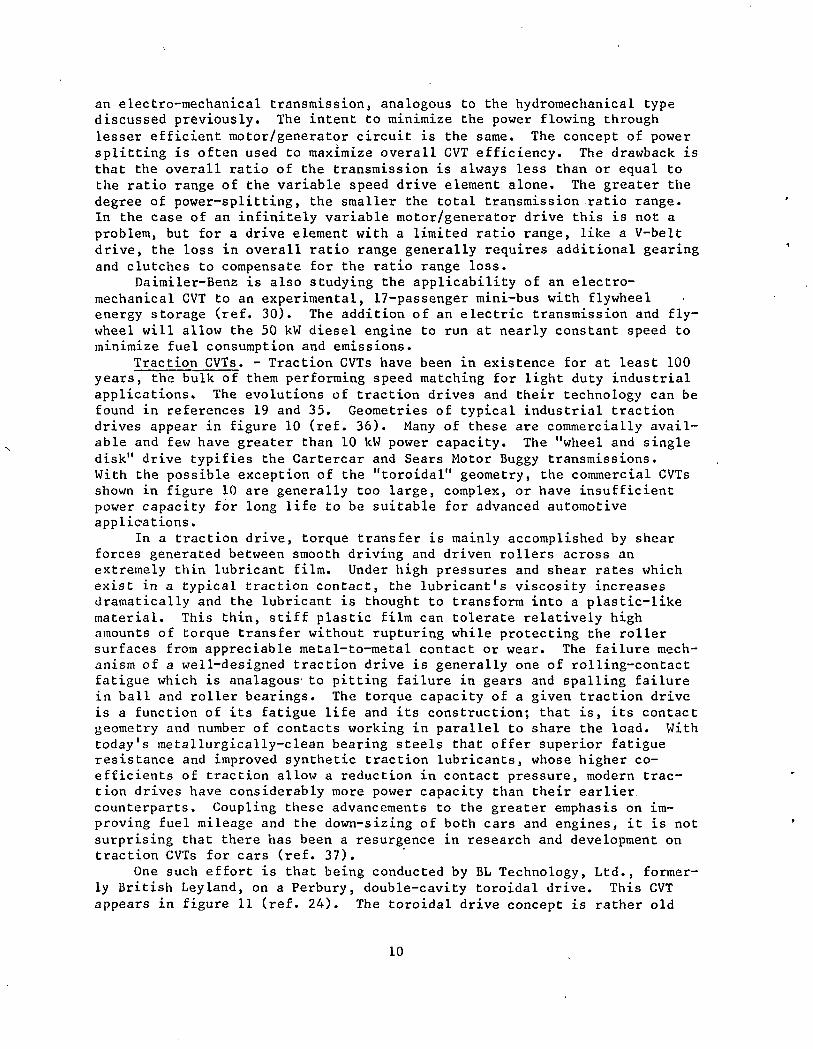
Traction CVTs. - Traction CVTs have been in existence for at least 100 years, the bulk of them performing speed matching for light duty industrial applications. The evolutions of traction drives and their technology can be found in references 19 and 35. Geometries of typical industrial traction drives appear in figure 10 (ref. 36). Many of these are commercially available and few have greater than 10 kW power capacity. The "wheel and single disk" drive typifies the Cartercar and Sears Motor Buggy transmissions. With the possible exception of the "toroidal" geometry, the commercial CVTs shown in figure 10 are generally too large, complex, or have insufficient power capacity for long life to be suitable for advanced automotive app 1 iC'a t ions.
In a traction drive, torque transfer is mainly accomplished by shear forces generated between smooth driving and driven rollers across an extrelnely thin lubricant film. Under high pressures and shear rates which exist in a typical traction contact, the lubricant·s viscosity increases dramatically and the lubricant is thought to transform into a plastic-like material. This thin, stiff plastic film can tolerate relatively high amounts of torque transfer without rupturing while protecting the roller surfaces from appreciable metal-to-metal contact or wear. The failure mechanism of a well-designed traction drive is generally one of rolling-contact fatigue which is analagous' to pitting failure in gears and spalling failure in ball and roller bearings. The torque capacity of a given traction drive is a function of its fatigue life and its construction; that is, its contact geometry and number of contacts working in parallel to share the load. With today·s metallurgically-clean bearing steels that offer superior fatigue resistance and improved synthetic traction lubricants, whose higher coefficients of traction allow a reduction in contact pressure, modern traction drives have considerably more power capacity than their earlier. counterparts. Coupling these advancements to the greater emphasis on improving fuel mileage and the down-sizing of both cars and engines, it is not surprising that there has been a resurgence in research and development on traction CVTs for cars (ref. 37). .
One such effort is that being conducted by BL Technology, Ltd., formerly British Leyland, on a Perbury, double-cavity toroidal drive. This CVT appears in figure 11 (ref. 24). The toroidal drive concept is rather old
10

(first patented in 1877). It.is also rather.well-explored, having}been investigated by the G.M. Research Laboratory in the early 30's and late 50's, demonstrated in a 1934 Austin-Hayes, later in a 1957 Hillman-Minx and
'also in a 1973 Ford Pinto, but with offset rollers. The B.L./Perbury transmission was installed in a medium size test car having a 4-cy1inder, 60 kW engine. The test car showed fuel mileage improvements of 15 t020 percent for an average mix of European driving (ref. 24). Also, acceleration times were comparable to a manual transmission car having 10 percent higher power/weight ratio and driven by a skilled driver. However, the future production picture of this transmission remains unclear at this time.
There are several other projects of recent taking advantage of the latest technology to develop traction CVTs for vehicle use. A nutating, double-cone traction CVT being developed by Vadetec is one such example (ref. 38). Several prototypes have been built and tested, one of these reportedly showing successful operation as part of a tractor drive train.
The Fafnir Bearing Division of Textron is currently working on a planetary, cone roller type CVT (ref. 39). This transmission is directed toward the mobile equipment market, particularly as.an inexpensive replacement to hydrostatic transmission in garden and light duty tractors up to about 37 kW.
It is likely that the smoothness, simplicity and potentially high efficiency of traction CVTs will encourage more entires into the field in the future.
CVT Design Studies
Design requirements. - As part pf the DOE Electric .and Hybrid Vehicle Program, 9-month preliminary design studies were performed on four CVT concepts under contract to NASA Lewis Research Center. The CVT concepts were designed for a 1700 kg (3750 1b) vehicle equipped with a 14 000 to 28 000 rpm energy storage flywheel. The goal of NASA Lewis's CVT program is to provide enabling CVT technology to permit commercialization in the 1985-1990 time frame. It was expected that these four preliminary design studies would yield one or more promising CVT concepts which could be selected for detailed design, fabrication and testing. Another expected result of these studies would be the identification of new technology advancements needed to make each of the CVT's viable for electric vehicles.
The basic design requirements and general drive train arrangement used in these studies are shown in figure 12. These design requirements were not selected for any specific vehicle but were arbitrarily chosen to evaluate all CVT concepts on a common basis. A flywheel electric vehicle system is a logical choice for a CVT study not only from the standpoint that some form, of CVT is an absolute necessity but, moreover, the selected CVT must have a particularly broad ratio range. This is because the flywheel speed may be at its maximum value when the vehicle's speed is at its 10west~ or vice ·versa. In this particular study the speed ratio of the CVT was to be continuously controllable from flywheel speeds of 14 000 to 28 000 rpm to 'transmission output speeds of zero to 5000 rpm. However, as an option, the minimum CVT output speed could be 850 rpm and a slipping clutch element be used on the output side of the CVT to drop the speed from 850 rpm to zero. Using the 850 rpm minimum output speed, the CVT's ratio range is 11.8 to 1. In addition to the requirements listed in figure 12, the CVT must be capable
11·

of bi-directional power flow for flywheel regeneration during braking; capable'of handling normal driving shock loads; and· have some clutching means to disengage and re-engage the flywheel from the rest of the drive train. The CVT did not have to have reverse rotation capability since the electric motor could be used to back-up the vehicle. The clutch between the,motor and the differential permits flywheel charging when the vehicle is stopped.
The eVT designs were to be evaluated on the basis of the following criteria in order of overall importance:
1. Efficiency - particularly at operating conditions where the CVT spends most of its time.
2. Cost - on the basis of 100 000 units per year. 3. Size and weight - comparable to or less than present automatic
transmissions. 4. High reliability - 2600 hours with 90-percent reliability at the
weighted average conditions noted in figure 12. 5. Noise - minimize its generation and maximize its containment in the
housing. 6. Controls - provide driver "feel" as close to current automobile
transmissions as possible. 7. Haintainability - equal or better than current automobile trans
missions. Description of CVT concepts. - Preliminary design layouts of the four
CVT studies listed in table I appear in figures 13, 15 to .17. A general description of each CVT concept will be given in this section. For those interested, a more thorough discussion can be found in reference 40 and specific details in references 41 to 44.
Steel V-belt CVT. - A preliminary layout of Battelle's steel V-belt CVT (ref. 41) appears in figure 13. This transmission uses two V-belts in series to achieve, the minimum required ratio range of'11.8 to 1. An output nlodulation clutch is used to lower the output speed from 850 rpm down to zero and provide over-torque protection. A 2.8 to 1 spur gear set reduces the flywheel speed entering the high-speed belt. The belts are only used as reducers, varying from about 1:1 to 1:3.9 for the high-speed belt and from 1:1 to 1:3.3 for the low-speed belt. A microprocessor-controlled hydraulic system controls belt shifting and regulates the axial clamping force between pulleys to achieve the best compromise between drive efficiency and belt life.
Battelle's steel V-belt concept had received some early hardware development by Battelle Columbus Labs back in the 1960's. The construction of their belt as shown in figure 14 is similar to that of the van Doorne V-belt (ref. 28). The van Doorne V-belt was briefly discussed in a previous section. The belt is composed of a stack of solid cross-struts gathered together by a nested set of thin, steel bands. The bands' lie freelY'on the' top of these cross-struts allowing relative motion between the individual bands themselves and also between the band set and the struts. The ends of the struts contact the face of the V-shaped pulleys. This type of belt is termed a compression belt since the driver pulley pushes the driven pulley through the stack of cross-struts. The set of bands keep the struts from buckling. Consequently, the bands carry high-tensile forces and are subjected to high bending stresses as they travel around the pulleys. It is basically the bending fatigue strength of these bands that limits the torque
12

capacity and minimum pulley diameters (or the ratio range) of the drive. Also, since the bands slide over each other and over the struts as the belt moves, proper lubrication and material selection are important to prevent de~tructive surface galling. ,
Flat rubber belt CVT. - Figure 15 illustrates the variable pulley diameter, flat rubber belt CVT concept of Kumm Industries (ref. 42). A pair of ,variable diameter pulleys are used in combination with differential gearing (not shown) to achieve the required speed variation. The differential gearing is used only in the IIlowll speed mode to attain zero output rpm while "the 4-to-l ratio range (2:1 to 1:2) of the pulleys is used in IIdirect" drive to achieve maximum vehicle speed in the "high" speed mode. The "low" arid "high" speed modes are separated by synchronous clutching. Step-down gearing from the flywheel insures that the pulley speeds never exceed about
,10 000 rpm. The flat belt is in contact with a set of drive elements or cross
struts. The ends of these drive elements are contained in guideways or circular arcs which have been machined in a pair of inner discs and a pair 'of outer, discs, but in opposite directions (see figure 15). The radial position of these drive elements; hence, pulley diameter, is determined by the intersection of the inner-disc guideways that are curved one way and the guideways of the outer discs that are curved in the opposite direction. As the inner and outer discs are rotated relative to one another by a hydraulic rotary actuator, the drive elements are moved radially in and out, changing drive ratio. A hydraulic control circuit is used to control the actuator which also provides sufficient belt tension to prevent slippage without overloading.
Toroidal traction CVT. - The preliminary design layout of AiResearch's toroidal traction CVT appears in figure 16 (ref. 43). The double-cavity toroidal drive, containing two power rollers per cavity, is permanently connected to differential gearing to form a single mode, power "recirculating ll CVT. The differential gearing expands the 5.8 to 1 ratio range of toroid~l drive section to cover the 0 to 5000 rpm output sp~ed requirement of the study. The double toroidal drive elements are similar in many respects to the drive elements in the GM Toric drive, the Austin-Hayes tiansmission and the Perbury drive as discussed earlier.
The input shaft, through the input reduction gear set, drives the two outer toroids and the sun gear of the output differential. The tilting of the power rollers varies the speed of the inner toroids which is connected to the ring gear of the output differential via the tra~sfer shaft. The power that is recirculating between the toroidal cavities and the output differential is always somewhat greater than the output power. A mechanical loading cam mechanism automatically increases the clamping force between the rollers and toroids in proportion to the transmitted torque. This insures. that the traction contact will always have sufficient load to prevent slip while minimizing contact overloading under light torque conditions. The CVT ratio is controlled by a pressure-balanced hydraulic control system. This sys te'm liS teers ll the power rollers into a new "tilt" position when the com-' mand pressure acting on the roller's reaction piston is no~ exactly balanced by the traction forces acting on the roller. Commanding more torque increases hydraulic pressure, causing the rollers to upshift the transmission which, in turn, causes the vehicle to accelerate and load the transmission.
13

This ,type of "torque controlled" ratio change system is ideally suited for' flywheel drive systems where even small changes in speed can mean large surges of power. "
Cone-roller CVT. - The mechanical arrangement of the Bales-McCoin coneroller traction CVT appears in figure 17 (ref. 44). In this design, the variable ratio traction assembly is connected to output planetary differential through a set of bevel/helical idler gears. As in some of the prior examples, there is an output differential which expands the approximate 3.6 to 1 ratio range of the traction roller assembly to achieve output speeds from 5000 down to 850 rpm. A modulating clutch (not shown) is used to attain output speeds down to zero.
The traction assembly consists of a central traction roller surrounded by four cone rollers whose axes are inclined. By inclining the cones, their inner contact surface can be made parallel to axis of the roller. The wormscrew drive shown in figure 17 axially positions the central roller to change speed ratio. Bevel gears attached to the end of the cones drive the ring gear of the output planetary through the idler gears. The sun gear of the planetary is driven by the input shaft which is part of the traction roller ball spline. The output shaft is connected to the "planet carrier.
The cones are loaded against the central roller with individual hydraulic pistons. The hydraulic pressure, hence contact load, is regulated by a novel ~icroprocessor control system to attain the minimum load needed to prevent significant roller slip at any given operating conditions. The control system senses the instantaneous change in slip rate using speed measuring encoders attached to the roller and cone shafts and a linear transducer sensing the axial position of the roller. Based on these signal inputs, the microprocessor continuously computes whether to increase or decrease cone pressure, depending on the current slip rate. Ideally, with this type of "updating" loading control system, efficiency and fatigue life of the traction contacts can be improved. However, with the proposed design, control system reliability and response time needs to be established."
Comparisons of predicted performance. - The efficiency, weight'and size for each of the CVT preliminary designs were evaluated. The calculated efficiency was based on installed power losses which included bearing, "gear, seal, traction contact or belt contact losses and the losses associated with the hydraulic system. The calculated efficiencies of the four CVT concepts are compared in figure 18 at an output power of 16 kW (22 hp) and speed of 3000 rpm for different flywheel speeds. This operating condition "is the nominal, weighted averaged power condition used in the study to det~rmine the reliability of the CVT. Predicted CVT efficiencies over the full range of speed and power conditions can be found in references 41 and 44. FrOIn figure 18 it is apparent that flywheel speed has little effect on efficiency. At this power level, the belt type CVTs ~ppear to have about a 4-point efficiency advantage over the traction types. However, all predicted efficiencies are significantly higher than the nominal 75 to 85 percent values measured for current automatic transmissions (refs.' 45 to 47). Predicted efficiencies at a low speed cruise condition'where output power is only 5 kW (7 hp) are approximately 92, 90, 92 and 89 percent for the steel V-belt, flat belt, toroidal traction and cone-roller traction CVTs, respectively (ref. 40). Because the typical duty cycle of a car is, on the whole,
14
..

quite modest, the relatively .good predicted performance of these CVTs at low power levels is quite significant to drive train energy economy.
One of the criteria for the preliminary design was that the size and weight should not be significantly greater than present automotive transmissions of equal power rating. No restriction on shape or input/output relative position (such as inline or offset) were given. As seen by the layouts in figures 13, 15 to 17, the shapes vary considerably. Table II gives dimensions of the four CVT designs. The two traction CVTs have inline input and output shafts, whereas both belt-type CVTs have offsets.
The estimated weights of the four CVT designs are also given in table II. All are equal or less than the weight of comparable automatic transmissions which generally are in the range of from 68 to 82 kg (150 to 180 lb) for comparably sized cars.
Cost estimates based on high volume manufacture of 100 000 units per year were difficult to make because detailed drawings were not prepared in the preliminary design. However, there are many similarities between the parts of these CVTs and present automatic transmissions. Machining and processing techniques for the unique CVT components are or will be well established by the time production commences. It is, therefore, expected that costs per pound for the CVTs would be similar or only slightly higher than that of present automatic transmissions.
Required Technology Advancements
Before these CVT concepts will be viable for large-scale electric vehicle application, extensive testing and development will be required. The four CVT concepts have received different levels of previous development. None of them are presently in production for automotive use. However, prototype transmissions using either the steel V-belt, toroidal traction, and cone-roller traction drive concepts have been fabricated and have received some road testing in internal-combustion engine automobiles. The flat belt cvr, on the other hand, has not yet been fabricated or tested.
To satisfy the design requirements and criteria of this program, each of the cvr concepts require unique components and advancements in technology as identified by the contractors in references 41 to 44.
For the steel V-belt CVT, the selection of band material and determination of its fatigue strength is of prime importance. Cost effective means of fabricating the band and the struts of the steel V-belt will need to be developed. The electrohydraulic control valves required for pulley actuation will require some development to be cost effective in an automotive system.
The flat belt CVT has been designed to use existing fiat belt technology. It is possible that improved flat belt construction, perhaps as described in reference 42, could give improved belt life or allow greater bending stresses to be used in the design of the belt. The variable pulley 'concept, not having been fabricated or tested, will require some development to perfect its operation. In addition, the fabrication of strong, lightweight drive elements must be made cost effective, possibly by using extrusion or casting processes.
For the traction type CVTs, some improvements in the traction fluids commercially available are desriable. Traction fluids tend to have too a
15

high viscosity at low temperatures so a decrease in the viscosity index would be welcome. Also traction fluids tend to trap and retain air at low temperatures and pressures. Although this is not a serious problem to the drive's operation, it is desireable to minimize air entrainment for automo-
,tive systems. In addition, more test data would be useful on the traction': properties of these traction fluids under conditions simulating those in actual transmission service.
All four of the CVT concepts require control systems that res~ond' rapidly to driver commands and smoothly control the magnitude and direction of power flow through the CVT. This requirement is difficult since the CVT is located between the flywheel and the vehicle, both of which have high inertia.
It is desired that the control system provide a driver feel similar to that of current automobiles with automatic transmissions. Whether similar driver "feel" could be achieved with a flywheel-electric vehicle or whether drivers would accept a different driveability characteristic are questions which as of now are unanswered. In tomorrow's automobile, the transmission control system would likely be integrated with the vehicle control system utilizing a microprocessor. Control systems using microprocessors should potentially provide smooth, reliable operation of a CVT equipped, flywheelelectric vehicle.
Based upon the encouraging results of this preliminary design study, a follow-up program is underway to detail design, fabricate and test one of the CVT concepts and possibly a second. The Kumm flat-rubber belt CVT has already received funding for tests on the variable speed components. Pending encouraging results from these component tests, the entire CVT will be constructed and tested.
CONCLUDING REMARKS
CVT technology has shown slow but steady progress through the years. Increasing concern over our diminishing petroleum resources, coupled with recent technological adyancements in materials and design techniques, has hastened the likelihood that a commercially viable, automotive CVT will be produced. Some of the CVT designs reviewed in this paper are already nearing the point of commercial acceptance and undoubtedly there will be improvements with time. The CVT field also offers plenty of opportunity for innovation.
In the case of electric and hybrid vehicles, CVTs are beneficial" provided they are efficient, which most are, possessing good reliability characteristics and are not too costly. In the case of flywheel-equipped electric vehicles, some form of CVT is a necessity.
In assessing the general level of CVT technology, it-appears that the basic technology is in hand to make most CVTs functional. However, power limits, cost and reliability factors are largely unknown. Furthermore, identification of critical technology elements where improvements can be obtained is warranted. Full scale demonstration of advanced CVT technology as applied to electrical vehicles is also needed. These are some of the goals of the NASA CVT technology program, the preliminary CVT design phase of which was reported in this paper.
16
": "':"".

This paper has attempted to "show the wide variety of approaches to , developing a successful automotive CVT. Examples of electrical, hydromechanical, hydrokinetic, rubber and metal belt, chain and tractiori"type
,CVTs as installed in experimental vehicles were presented. Each,of the CVT ;"types, given sufficient development, would provide satisfac tory operation on
a battery electric or hybrid electric vehicle, although some are obviously more desirable than others. In this regard, the belt and traction designs look particularly promosing for advanced CVT applications with belt drives appearing somewhat nearer term.
REFERENCES
1. Raynard, A. E.; and Forbes, F. E.: Advanced Electric Propulsion System Concept for Electric Vehicles. (AiResearch-79-l6l82, Garrett Corp.; Contract DEN3-81) DOE/NASA/008l-79/l, NASA CR-15965l, 1979.
2. State-of-the-Art Assessment of Electric Vehicles and Hybrid Vehicles. NASA TM 73756, 1977.
3. Heldt, P. M.: Automatic Transmissions. S.A.E. Trans., vol. 40, no. 5, May 1937, 206-220.
4. DeBono, E.: Eureka: An Illustrated History of Inventions from the Wheel to the Computer. Holt, Rinehart, and Winston, New York, 1974, p. 33.
5. Hodges, D. and Wise, D. B.: The Story of the Car. Hamlyn Publication Group, Ltd., London, 1974, p. 18.
6. Sloan, Alfred P.: My Years with General Motors. Doubleday and Company, Inc., New York, 1964.
7. Clymer, F., Historical Motor Scrapbook. Vo1s. 1 and 2, Clymer Motor Publications, Los Angeles, California, 1944. ,
8. Caris, D. F.; and Richardson, R. A.: Engine-Transmission Relationships for High Efficiency. S.A.E. Trans., Vol. 61, 1953, pp. 81-96.
9. Improved Technology is Giving an Old Principle a New Drive. Monsanto Magazine, Summer 1974, pp. 14-16. '
10. Carson, R. W.: Focus on Traction Drives: 100 Years of Traction Drives. Power Transmission Design, May 1975, pp. 84 and 88.
11. Perry, F. G.: The Perbury Transmission. ASME Paper No. 80-GT-22, 1980. 12. Chana, H. E.; Fedewa, W. L.; and Mahoney, J. E.: An Analytical Study of
Transmission Modifications as Related to Vehicle Performance and Economy. S.A.E. Paper 770418, 1977.
13. Radtke, R. R.; Unnewehr, L. E.; and Freedman, R. Continuously Variable Transmission with Emission No. 810107, Feb. 1981.
J.: Optimization of a Constraints. SAE Paper,
14. Huntley, P.: Design Factors of Hydromechanical Transmissions for Passenger Cars. Fourth International Symposium on Automotive Propulsion Systems, April 18-22, 1977, CONF-770430, 651-671.
, 15. McAlevy, R. F. III: The Impact of Flywheel-Transmissions on Automobile Performance: A Logical Basis for Evaluation. UCRL-52758, 1979.
16. Edson, D. V.: Researchers Advance Heat Engine/Flywheel Technology. Design News, Sept. 8, 1980, pp. 127-140. '
17. Strauch, S.: Flywheel Systems for Vehicles. Proceedings of Electric and Hybrid Adv. Technology Symposium, Dec. 1980, pp. 221-234.
17

18. Kirk, Robert S. and Davis, Philip W., "A View of the Future Potential of Electric and Hybrid Vehicles," Electric and Hybrid Vehicle Program· Quarterly Report, DOE/CS-0026-l0, May 1980. .
. 19. Loewenthal, S. H.: A Historical Perspective of Traction Drives 'and Related Technology. Proceedings of NASA Advanced Power Transmission Symposium (to be published).
20. Edson, D. V.: Continuously Variable Transmission: A Concept Whose Time Has Come? Design News, Jan. 5, 1981, pp. 42-55.
21. Baudin, P.: Continously Variable Transmissions for Cars with High Ratio Range. SAE Paper No. 790041, 1979.
22. Scott, D.: Volvo 343; Swedish Smoothie with a Belt Transmission. Popular Science, Jan. 1977, p. 81.
23. Scott, D.: Belt-Drive Automatic Programmed for Economy. Automotive Eng., Vol. 86, No.8, Aug. 1978, pp. 98-99.
24. Stubbs, P. W. R.: The Development of a Perbury Traction Transmission for Motor Car Applications. ASME Trans., J. of Mech. Deg., Vol. 103, No.4, Jan. 1981, pp. 29-40.
25. Castelli, P. and Morello, L.: The Optimization of Engine Transmission Matching Reduces Fuel Consumption. ASME Paper No. 80-GT-130, 1980.
26. Nomazawa, A. et al.: Toyota Four Speed Automatic Transmission with Overdrive. SAE Paper No. 780097, 1978.
27. Satchwell, D. L.: An Advanced Energy Storage Unit for a U.S. Postal Service Delivery Vehicle, 1977 Flywheel Technology Symposium Proceedings, G. C. Chang and R. G. Stone, eds., CONF-77l053, 1978, 69-73.
28. Scott, David: Belt-Drive CVT for '82 Model Year. Automot. Eng., vol. 88, no. 2, Feb. 1980, 136-140.
29. Dittrich, o. and Steuer, H.: Power Transmission - How to Increase Torque Without Increasing Current. Electric Vehicle Developments, June 1979, pp. 7-9.
30. Scott, D.: Regenerative Braking Cuts Bus Fuel Needs. Automotives Eng., Vol. 87, No. 10, Oct. 1979, pp. 102-107.
31. Israel Claims EV Breakthrough. EV Focus, May 1, 1978, p. 8. 32. Kost, R. and Luchter, S.: Improving Automobile Fuel Economy with Ad
vanced Transmissions. IECEC Paper No. 779004, 1977, pp. 18-25. 33. Carriere, o. L.: Differential Split Power Transmission for a Single
Shaft Passenger Car Gas Turbine Engine. ASME Paper 80-GT-19, Mar. 1980~ 34. Towgood, D. A.: An Advanced Vehicular Flywheel System for the ERDA
Electric Powered Passenger Vehicle. Flywheel Technology Symposium. CONF-77l053, 1978, 63-68.
35. Loewenthal, S. H.: Advanced Continuously Variable Transmissions for Electric and Hybrid Vehicles. Proceedings of Electric and Hybrid Vehicle Advanced Technology Seminar, Dec. 1980, pp. 427-470.
36. Yeaple, F.: Metal-to-Metal Traction Drives Now Have a New Lease on Life. Prod. Eng., Oct. 1971.
37. McCormick, D.: Traction Drives Move to High Powers. Des. Eng., Dec. 1980, 35-3':}.
38. Continuously Variable Transmission Has High Power Density. Automot. Eng., Vol. 87, no. 9, Sept. 1979, pp. 44-47.
39. Dickinson, T. W.: Development of a Variable Speed Transmission for Light Tractors. S.A.E. Paper 770749, Sept. 1977.
18

}: .',
40. Parker, R. J.; Lowentha1",~. H.; and .. ,Fis,cher , G. K.: Design' Studies of Continuously Variable Transmis'sions' for Electric Vehicles. DOE/NASA/1044-12, NASA TM-81642, 1981.
41. Swain, J. C.; Klausing, T. A.; and Wilcox, J. P.: 'Design Study of Steel V-Belt CVT for Electric Vehicles. DOE/NASA/Oll6-80/l, NASA CR-159845, 1980.
42. Kumm, E. L.: Design Study of Flat Belt CVT for Electric Vehicles. (P-1006, Emerson L. Kumm; DEN3-114) DOE/NASA/0114-80/i, NASA CR-159822, 1980.
43. Raynard, A. E.; Kraus, J. H.; and Bell, D. D.: Design Study of Toroidal Traction CVT for Electric Vehicles. (Rept-80-l6762, AiResearch Mfg. Co.; DEN3-ll7) DOE/NASA/0117-80/1, NASA CR-159803, 1980. '
44. Walker, R. D.; and McCoin, D. K.: Design Study of a C6ntinuous1y Variable Cone/Roller Traction Transmission for Electric Vehicles. DOE/NASA/0115-80/1, NASA CR-15984l, Sept. 1980.
45. Bujold, M. P.: Small Passenger Car Transmissio~ Test-Chevrolet 200 Transmission. (ERC-LIB-79168, Eaton Engineering and Research Center; DEN3-124) DOE/NASA/0124-1, NASA CR-159835, 1980.
46. Bujold, M. P.: Small Passenger Car Transmission Test-Ford C4 Transmission. (ERC-LIB-8060, Eaton Corp.; DEN3-l24) DOE/NASA/0124-2, NASA CR-159881, 1980.
47. Bujold, M. P.: Small Passenger Car Transmission Test-Chevrolet Citation 125 Transmission. DOE/NASA/0124-4, NASA CR-159883, 1980.
19

TABLE I. CVT CONCEPTS AND CONTRACTORS : ~
FOR PRELIMINARY DESIGN STUDY
CVT,concept Contractor Reference
Variable pulley,~ Battelle Columbus Labs 41
I steel V':':belt Columbus, Ohio , ' l Variable pulley, Kumm Industries, Inc. 42 ,
flat rubber belt Tempe, Arizo~a ,
Toroidal traction Garrett Corp., AiRese~rch 43 Mfg. Co. of California . Torrance, Californii
Cone-roller traction Bales-McCoin Tractionmatic 44 El Paso, Texas
-- ---
TABLE II. - DIMENSIONS AND WEIGHTS OF CVT CONCEPTS
Dimensions, cm (in.) Contractor's estimated
Concept Length Width Height Offset weight, kgOb)
Steel V-belt 52.2(20.6) 31.503.8) 24.8(9.8) 6.1(2.4) 70.3(55)
Flat belt 30.1(11.9) 48.4(19.0) 47.6(18.8) 28.1(11.1) 44.5(98)
Toroidal traction 67.3(26.5) 23.8(9.4) 36.2( 14.3) 0 62.6(38)
Cone-roller traction 41.3(16.3) 27 .4( 10.8) 27 .4( 10.8) 0 31.8(70)
20

·' '<' ",
. '
1I«1$,t~
"Th, ..". lir.er ..... Pn""" TraumlMlOII"
THE AUTOMOBILE.
=====TH E===
Gearless Transmission The I.... r"lIDlblJH ro .. Dotb ,Jusan ... C .. aerclal ,,~Ides.
DoeI""".,. Enllrel,WICA Ihe v .. of Gtan Guru ... UDbl:llltedN_ber of',....
1906
aM .. a EmOAD IlANOB OP SPEI!DS POItWARD OR; REVER.Sa, DIRECT DR,IVB ON HIOtt SPEED. Sla,'. Lev.r eoattGl, ELiMINATINO eNTIR:ELY AU of til, Otrllc::ultt.ll!JIcont,n4 I. til •• rn ... t P ..... of TnumlAlou Emplo,.la, 0.0" wltll '1,11' AUaad. Troubl ...
Built in. _ TWO Sizes For Light and Heavy Cart . , Can Be Uaed With Either Shaft or Ch.in Drive.
We Furni.h the Tranuni •• ion AI Shown Herewith to Include Fly-wheel and Direct Clutch. The Frame il 0 f Steel. Bearin,.. Balli and Rollera. Material and Workmanlhip of Highelt Grade.
Friction Surfacel
only in ule on Intermediau Speecb Forward and Reverse.
nawl'l TrlDS.wIOll Jastallt ... Car
Write For Catalogue and Prices To-day. , Thoroughly Tested During the P.,t Two Years.
Side Friction Whtlcl. Do Hoi
Rotate on Dine! Dr!",. Central Friction Wheel i, Driven 011 Inter. mediate Speed.
by Bolb Side Whech Prom Flywheel. Note ne DIr.ct CluIcb in Hub of the Fly.heel.
""" Put. Lets Strain on the Running Gear of. Car Than Any Other Transmi •• ion.
GEAm.ESS lUANSMISSION CO., Ilochester, N. Y.
Figure 1. - An early automotive friction drive, circa 1906 from ref. 7.
MOTOR AGE MARCH 7, 1907
··IT'S A STIlONGEP... PIlOP051TION THAN YOU HAV& IMAGIN&n"
DEALERS [lJk~RI) U S t K S ~~
..
THE FRICTION DRIVE' CAR • ~ ~ 5 NEW MODELS .. ,.. ~\ "No Filled Speed" HAn,. Speed D •• I'.... .,
r .... e.I1 're ."I"lcoll, IIIIL .... 1<11 C,nlne ,.otmo ".1 Filii .. GI .... eon
i "You caD DO' MeaN Mltotr ' ... lu. ror th, prl~." Write 'O~ detailed de.-r1ptloD. TUE LAM.HKtc.T·o rlCl. T10N J,RI\'I!:" bu pro • .,D\n IbOM llu!pUt.alOllod,UUltuu.01ethodor lraIuimlellOD I, Do\ oob' poMlble, bu' ... '_, ..,_ ..... lIue_. ",ne, Te,e.,booe or Wire U'o
lo."~ t.n lIVe 'en
A
Pmr. Stcee"
lor Jean
i THE BUCKEYE MANUFACTURING CO., - ANDERSON, IND., U. S. A. Good D ...... Aa.nII Wanle' I ... rew Lot. Uti.. Member1 A.merlcan Motor Car Manufaetur&n' Alsoclatlon, Ne" York, Write for Special Art CatalOl'lI1
Figure 2. - An early friction drive car advertisement (ref. 7).

Figure 3. - 1909 Carter Car equipped with a friction CVT. (Courtesy of Henry Ford Museu m, Dearborn, MI.)
1.0 ----~ Best motor efficiency operating line ---------- 4OD-A motor current limit
.9 Horsepower
.8
25 «- 20 ~ --~- ~-... -- 15
~ c: '" 'u is .7
7.5
.6
.~~'----~~--~~~--~=-----~~--~~----~
Figure 4. - Typical efficiency map for series wound DC-motor (ref. 2),

~ UI U IIC UI 110 ,.: U Z UI
ti ii: ... UI
... z UI U IIC ... 110
,.: u Z UI
U ii: ... UI
"
'II' ",'"
."-,,' I", • l' '
100
90
80
70
60
50
40
30
20
10
00 100 200 PERCENT OF RATED POWER CS-8o-4882
100
90
80
70
60
50
40
30
20
10
0
Figure 5. - Performance characteristics of a D. C. shunt electric motor (ref. ll.
I --IL I '")
I / I
I
I
I 1 RATED TORQUE
I / II
/ /
L
/ I
I
100 200 PERCENT OF RATED POWER
Figure 6. - Performance characteristics of a A. C. Induction electric motor (ref. II.
CS-80-4880
100
90
80
... ffi 70 U II: ... A. 60 ,: U z !!! 50 u ii: ::; 40
30
20
10
20!50~ R~M
~< r> /' -~ 1-- - 30.000 RPM
" ,,," 15.000 RPM ,.
XX [\ 1>'7.500 RPM / I I I
\I 6.000 RPM
~ I I I
, 4.500 RPM f f f
.~ 3.000 RPj
\ ......... ~ ~AXIMUM TORQUE
,1.500 RPM I , , , I
o 40 80, 120 160 200 240 260 PERCENT RATED POWER
Figure 7. - Performance characteristics of a A. C. Induction electric motor using variable frequency control Iref. 1l.
CS-BD-48Bl
FLYWHEEL
FLUID COUPLING
MOTOR
/ VARIABLE V·BEL T 2.646: 1 TO 0.378: 1 .
WHEEL
GEARBOX 11.74:1
REAR AXLE DIFFERENTIAL
~ I I £"""R't ., .,' J; j; IS
~ TOOTHED BELT 2.25:1
CS-BO-4B8S
Figure 8. - Rubber V-Belt CVT for DOE/USPS delivery vehicle I ref. 2n
/ I

,.
.'"
THROTIlE
r'- f~AKE I I '- ____ _
L - ____ - ---I ~"~---~"I
SILENT/" CHAIN DRIVE
I ! DIFFERENTIAL
Vii TRANSMISSION I I ' :- GENERATOR
-L
CS-BO-4B73
Figure 9. - Electro-mechanical CVT for DOE/AIResearch flywheel ETV-2 vehicle (ref. 34).
)-Adl'
:
Figure 10. - Typical industrial traction drive geometries. (Courtesy of Design Engineering (ref. 36).

TILTABLE TOROIDAL ROLLERS
OUTPUT PLANETARY GEAR SYSlEM
CS-80-4879
Figure 11. - B. L. TechnologylPerbury traction CVT. 60 kW passenger car test Installation (ref. 24).
VEH. WT: 3750lbs MAX OUTPUT TORQUE: 330 ft-Ib MAX TRANSIENT POWER: 75 kW
14000 TO
28000 RPM.,
I I
r 0 :TO I 5000 : RPM I
,'r,------, ELECTRIC MOTOR
LCVT / / (INCLUDES /
RATIO CHANGE RATE: 2 sec 10% DE SIGN LIFE: 2600 h rs AT 16 kW;
21,000 rpm INI3000 rpm OUT
_,,- DIFFERENTIAL
/ ANCILLARY / LFLYWHEEL COMPONENTS) LCLUTCH
Figure 12. - CVT design study fly wheel-electric vehicle drive train.
'.
I
~

~'
LOW SPEED BELT-,
SYNCHRONIZING UNKAGE~\
\
MODULATING \
, , , , \
,- LARGE LOW SPEED PULLEY / \- SMALL HIGH SPEED PULLEY
/ \ __ PULLEY ACTUATING \ \ CYLINDER \ \ FIXED RATIO SPEED
.... ' OUTPUT , , , '\, /,HALL
SHAfT" ~ ~"",', .~,' ' EFFECT \ ".' Co ' " , , DIGITAL
- -"-- - " . - - ,----- - SENSOR '" " ~ _.
, -. ,
CLUTCH, '"
, ,
, , / " '/ SHAFT 1/ -I'I£~ SPLlNESJ 1ll.1~~w.-~.
, , 1 I 1
SMALL LOW SPEED PULLEY _I
, , , '
\ 1 '-HIGH SPEED BELT, \ :-LARGE HIGH , SPEED PULLEY , , '-COUNTERSHAFT
COUPLING
Figure 13. - Preliminary layout of Battelle's steel V-belt CVT (ref. 41).
A
END VIEW OF STRUTS A
Figure 14. - Steel V-belt construction (ref. 41).

r DRIVE ELEMENTS
,- INNER DISCS 1\ 1\
'\ /'
---r-.!i OUTER DISC"'\ I I I \ ~~"'-OUTER DISC
\ \
- FLAT BELT
FLAT BELT../ " " " SECTION B-B
..-ROTARY .-, ACTUATOR
Figure 15. - Preliminary layout of variable-ratio pulleys for Kumm's flat belt CVT (ref. 42).
VARIABLE-RATIO INPUT SHAFT - PLANETARY
\ DIFFERENTIAL INPUT RELEASE' TRANSFE.R OUTPUT GEAR SET -,
, SHAFT -\ I CLUTCH BRAKE BAND1 , I TORQUE ,
I \ LOADING \ LIMITING ' I CAM, I ,
INPUT REDUCTION I \ I \ CLUTCH -: , STAR GEAR SET-. I I POWER "']---1 /
I I 'ROLLERS-" I ,OUTPUT INPUT SHAFT : I \ i', I \ I SHAFT 28 000 TO , I I --=-=r ~" .I OTO I ~ r _.--- I
14000 rpm 7 I' ~\7 ~r n)~: \ '\~f~ r", I _ 5000 rpm;
\~ '"~~ ~j \~2~ ~ /
LUBE AND I
CONTROL / OIL PUMp..!
..... I
c::. FULL CAVITY ~ DUAL TOROIDAL TORQIDAL DRIVE OUTPUT SECTION SECTION
Figure 16. - Preliminary layout of AiResearch's torodial traction CVT (ref. 43).
" 'f
"
.,

t
<'t'
rCONE ENCODER
TRACTION ROLLER .,
CONE LOADER "7 ~ CLUTCH "7
t
, \ \ , ,
,CONE \ ,
\ \
, I I ,
I
I ~l ~, .,
rBEVEU I HELICAL
IDLER
/ -..:; '-ROLLER ENCODER I L, OUTPUT PLANETARY
L. INPUT PlANETARY
Figure 17. - Preliminary layout of Bales-McCoin's cone-roller traction CVT (ref. 44).
96. STEEL V-BELh
I =::::---J. ~IlT~
94 'E '" u ... 8-
> u tj u it ....
90
88 14000 21000 28000
FlYWHEEL SPEED. rpm
Figure 18. - Comparison of predicted CVT efficiencies at we ig hted ave rage ope rati ng conditions (ref. 40).

, I 2. Government Accession No. , 1. Report No. 3. Recipient's Catalog No.
I NASA TM-82700 4. Title and Subtitle 5. Report Date
CONTINUOUSLY VARIABLE TRANSMISSION - ASSESSMENT OF APPLICABILITY TO ADVANCED ELECTRIC VEHICLES 6. Performing Organization Code
I
511-58-12 7. Author(s) 8. Performing Organization Report No.
stuart H. Loewenthal and Richard J. Parker E-983 I
10. Work Unit No. .. 9. Performing Organization Name and Address
National Aeronautics and Space Administration 11. Contract or Grant No.
Lewis Research Center Cleveland, Ohio 44135
13. Type of Report and Period Covered
12. Sponsoring Agency Name and Address Technical Memorandum U. S. Department of Energy Office of Vehicle and Engine R&D " 14. Sponsoring Agency 6edeoReport No.
Washington D.C. 20545 DOE/NASA/51044 -23 15. Supplementary Notes
Prepared under Interagency Agreement DE-AIOl-77CS51044. Prepared for Electric Vehicle Council Symposium VI, Baltimore, Maryland, October 21-23, 1981.
16. Abstract A brief historical account of the evolution of continuously variable transmissions (CVT) for auto-motive use is given. CVT concepts which are potentially suitable for application with electric and hybrid vehicles are discussed. The arrangement and function of several CVT concepts are cited along with their current developmental status. The results of preliminary design studies con-ducted under contract to NASA for DOE on four CVT concepts for use in advanced electric vehi-cles are discussed. For these studies a 1700 kg (3750 Ib) vehicle with an energy storage flywheel I
was specified. Requirements of the CVTs were a maximum torque of 450 N -m (330 Ib -ft) , a maximum output power of 75 kW (100 hp), and a flywheel speed range of 14 000 to 28 000 rpm. System life was to exceed 2600 hours at a 90-percent probability of survival. Efficiency, size, weight, cost, reliability, maintainability, and controls were evaluated for each of the four con-cepts. The design studies were performed by Garrett/ AiResearch (torodial traction CVT) , Battelle Columbus Labs (steel V -belt CVT) , Kumm Industries (flat belt variable diameter pulley CVT) , and Bales -McCoin Tractionmatic (cone-roller traction CVT). All CVTs exhibited rela-tively high calculated efficiencies (86 to 97 percent) over a broad range of vehicle operating condi-tions. Estimated weight and size of these transmissions were comparable to or less than an equivalent automatic transmission.
17. Key Words (Suggested by Author(sll 18. Distribution Statement
Continuously variable transmission electric Unclassified - unlimited i .,
cars; Transmissions STAR Category 37 DOE Category UC-96
!
19. Security Classif. (of this report) 20. Security Classif. (of this page) 121. No. of Pages 122. Price'
Unclassified Unclassified -- I
• For sale by the National Technical Information Service, Springfield, Virginia 22161