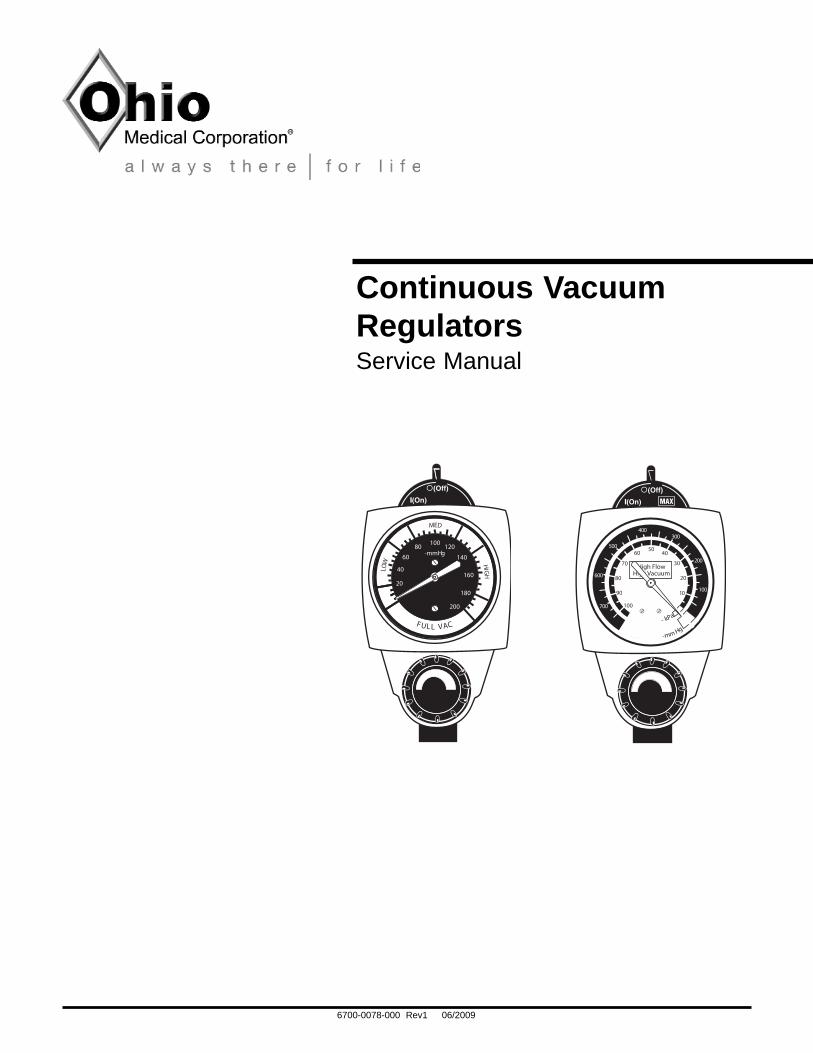
Continuous Vacuum Regulators - Frank's...
36
6700-0078-000 Rev1 06/2009 Continuous Vacuum Regulators Service Manual L O W ME D H I G H 20 40 60 80 100 120 140 160 180 200 -mmHg F U L L V A C High Flow High Vacuum 10 20 30 40 50 60 70 80 90 100 100 200 300 400 500 600 700 - k P a - m m H g
Transcript of Continuous Vacuum Regulators - Frank's...
6700-0078-000 Rev1 06/2009
Continuous VacuumRegulatorsService Manual
LOW
MED
HIGH
20
40
6080 100 120
140
160
180
200
-mmHg
FUL L VAC
High FlowHigh Vacuum
10
20
30
4050
60
70
80
90
100
100
200
300400
500
600
700
- kPa
-mm Hg

6700-0078-000 Rev1 06/2009
User Responsibility
This Product will perform in conformity with the descrip-tion thereof contained in this manual and accompanyinglabels and/or inserts, when assembled, operated, main-tained and repaired in accordance with the instructionsprovided. This Product must be checked periodically. Amalfunctioning Product should not be used. Parts thatare broken, missing, plainly worn, destroyed or contami-nated, should be replaced immediately. Should suchrepair or replacement become necessary, Ohio Medicalrecommends that a telephonic or written request for serv-ice advice be made to the nearest Ohio Medical ServiceOffice. This Product or any of its parts should not berepaired other than in accordance with written instruc-tions provided by Ohio Medical, or altered without theprior written approval of Ohio Medical’s SafetyDepartment. The user of this Product shall have the sole
responsibility for any malfunction which results fromimproper use, faulty maintenance, improper repair, dam-age, or alterations by anyone other than Ohio MedicalCorporation.
Important: Federal law in the U.S.A. and Canadarestricts this device to sale by or on the order of alicensed medical practitioner. This device is to be usedonly by persons who have been adequately instructed inits use.
Important: This document is not to be reproduced in anymanner, nor are the contents herein to be disclosed toanyone without the express authorization of OhioMedical Corporation.
The procedures described in this service manual shouldbe performed by competent individuals who have a gen-eral knowledge of and experience with devices of thisnature. No repairs should ever be undertaken or attempt-ed by anyone not having such qualifications.
Genuine replacement parts manufactured or sold byOhio Medical must be used for all repairs.
Read completely through each step in every procedurebefore starting the procedure; any exceptions may resultin a failure to properly and safely complete the attempt-ed procedure.
CCW Counterclockwise (Anti-clockwise)MAX Full Line Vacuum
in Hg Inches of mercurykPa Kilo pascals (kPa x 7.50 = mm Hg)LPM Liters per minutemm Hg Millimeters of mercury (mm Hg x .133 = kPa)°C Degrees Celsius°F Degrees FahrenheitN-m Newton-Meter (N-m x .737 = ft-lb)ft-lb Foot-Pound Force (ft-lb x 1.356 = N-m)oz OuncesDISS Diameter Index Safety SystemOES Oxequip SuctionNCG National Compressed Gases (Chemetron)NPT National Pipe Thread (USA)NPTF National Pipe Thread Female (USA)MPTS Multi-Purpose Therapy Standgal GallonPTFE Teflon®
User Responsibility
User Responsibility
6700-0078-000 Rev1 06/2009
Table of Contents
1/Precautions1.1 Definitions . . . . . . . . . . . . . . . . . . . . . . . . . . .1-11.2 Warnings . . . . . . . . . . . . . . . . . . . . . . . . . . . .1-11.3 Cautions . . . . . . . . . . . . . . . . . . . . . . . . . . . . .1-2
2/Scope2.1 North American Vacuum Regulators. . . . . . . .2-12.2 International Vacuum Regulators . . . . . . . . . .2-2
3/Description and Specifications3.1 Description . . . . . . . . . . . . . . . . . . . . . . . . . . .3-13.2 Specifications . . . . . . . . . . . . . . . . . . . . . . . . .3-2
4/Operation4.1 Equipment Set-up . . . . . . . . . . . . . . . . . . . . .4-14.2 Attaching the Safety Trap . . . . . . . . . . . . . . .4-24.3 Mode Selection . . . . . . . . . . . . . . . . . . . . . . .4-34.4 Setting the Suction Level . . . . . . . . . . . . . . . .4-44.5 Pre-Use Checkout Procedure . . . . . . . . . . . .4-44.6 Patient Set-up . . . . . . . . . . . . . . . . . . . . . . . .4-7
5/Cleaning and Sterilization5.1 Cleaning . . . . . . . . . . . . . . . . . . . . . . . . . . . . .5-1
5.1.1 Routine Exterior Cleaning . . . . . . . . . . .5-15.1.2 Internal Component Cleaning . . . . . . . .5-1
5.2 Sterilization . . . . . . . . . . . . . . . . . . . . . . . . . . .5-1
6/Troubleshooting
7/Service - Disassembly and Assembly7.1 Service Tools and Equipment . . . . . . . . . . . .7-17.2 Continuous Vacuum Regulators (All Models)7-1
7.2.1 Disassembly . . . . . . . . . . . . . . . . . . . . .7-17.2.2 Assembly . . . . . . . . . . . . . . . . . . . . . . . .7-3
7.3 Suction Level Limit Setting - Low Models ONLY . . . . . . . . . . . . . . . . . . . . . . . . .7-37.3.1 Low Vacuum Limiting Screws . . . . . . . .7-37.3.2 Vacuum Relief Valve Adjustment . . . . .7-4
7.4 Regulator Module . . . . . . . . . . . . . . . . . . . . . .7-47.4.1 Disassembly . . . . . . . . . . . . . . . . . . . . .7-47.4.2 Assembly . . . . . . . . . . . . . . . . . . . . . . . .7-5
8/Service Checkout Procedure8.1 Set-up . . . . . . . . . . . . . . . . . . . . . . . . . . . . . .8-18.2 Flow Test . . . . . . . . . . . . . . . . . . . . . . . . . . . .8-18.3 Gauge Test . . . . . . . . . . . . . . . . . . . . . . . . . . .8-2
8.3.1 High Vacuum Gauges ONLY . . . . . . . .8-28.3.2 Standard and Low Vacuum
Gauges ONLY . . . . . . . . . . . . . . . . . . .8-28.4 Regulation Test . . . . . . . . . . . . . . . . . . . . . . .8-28.5 Low Vacuum Regulators ONLY . . . . . . . . . . .8-28.6 Bleed Test . . . . . . . . . . . . . . . . . . . . . . . . . . .8-28.7 Leak Test - Supply Side . . . . . . . . . . . . . . . . .8-38.8 Leak Test - Patient Side . . . . . . . . . . . . . . . . . . .8-4
9/Maintenance9.1 General Maintenance of Suction Equipment .9-19.2 Recommended Maintenance Schedule . . . . .9-19.2.1 Maintenance Schedule . . . . . . . . . . . . . . . . . .9-19.3 Repair Policy . . . . . . . . . . . . . . . . . . . . . . . . .9-29.4 Technical Assistance . . . . . . . . . . . . . . . . . . .9-29.5 Return Instructions . . . . . . . . . . . . . . . . . . . . .9-2
10/Ordering Information10.1 Illustrated Parts . . . . . . . . . . . . . . . . . . . . . .10-110.2 Service Kits . . . . . . . . . . . . . . . . . . . . . . . . .10-210.3 Fittings and Adapters . . . . . . . . . . . . . . . . . .10-210.4 International . . . . . . . . . . . . . . . . . . . . . . . . .10-3
10.4.1 Regulator Options . . . . . . . . . . . . . . .10-310.4.2 Other Options . . . . . . . . . . . . . . . . . .10-4
AppendixInstallation procedure for Adapters/Probes and Fittings.A-1
6700-0078-000 Rev1 06/2009
1/Precautions
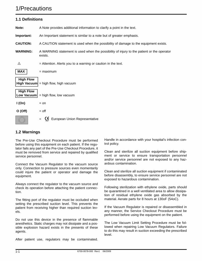
1.1 Definitions
Note: A Note provides additional information to clarify a point in the text.
Important: An Important statement is similar to a note but of greater emphasis.
CAUTION: A CAUTION statement is used when the possibility of damage to the equipment exists.
WARNING: A WARNING statement is used when the possibility of injury to the patient or the operatorexists.
= Attention. Alerts you to a warning or caution in the text.
MAX = maximum
High Flow High Vacuum = high flow, high vacuum
High Flow Low Vacuum = high flow, low vacuum
I (On) = on
O (Off) = off
= European Union Representative
1.2 Warnings
The Pre-Use Checkout Procedure must be performedbefore using this equipment on each patient. If the regu-lator fails any part of the Pre-Use Checkout Procedure, itmust be removed from service and repaired by qualifiedservice personnel.
Connect the Vacuum Regulator to the vacuum sourceonly. Connection to pressure sources even momentarilycould injure the patient or operator and damage theequipment.
Always connect the regulator to the vacuum source andcheck its operation before attaching the patient connec-tion.
The fitting port of the regulator must be occluded whensetting the prescribed suction level. This prevents thepatient from receiving higher than required suction lev-els.
Do not use this device in the presence of flammableanesthetics. Static charges may not dissipate and a pos-sible explosion hazard exists in the presents of theseagents.
After patient use, regulators may be contaminated.
Handle in accordance with your hospital’s infection con-trol policy.
Clean and sterilize all suction equipment before ship-ment or service to ensure transportation personneland/or service personnel are not exposed to any haz-ardous contamination.
Clean and sterilize all suction equipment if contaminatedbefore disassembly, to ensure service personnel are notexposed to hazardous contamination.
Following sterilization with ethylene oxide, parts shouldbe quarantined in a well ventilated area to allow dissipa-tion of residual ethylene oxide gas absorbed by thematerial. Aerate parts for 8 hours at 130oF (54oC).
If the Vacuum Regulator is repaired or disassembled inany manner, the Service Checkout Procedure must beperformed before using the equipment on the patient.
The Low Vacuum Limit Setting Procedure must be fol-lowed when repairing Low Vacuum Regulators. Failureto do this may result in suction exceeding the prescribedlevel.
1-1
6700-0078-000 Rev1 06/2009
Precautions/1
1.3 Cautions
Do not lubricate any internal components of the regulatormodule.
Do not use any Loctite® products to seal the fitting andadapter port threads (or products which containMethacrylate Ester as an active ingredient).
Only competent individuals trained in the repair of thisequipment should attempt to service it.
To help prevent aspirate from entering the regulator, as aresult of misuse, an Overflow Safety Trap and suction fil-ter should be attached prior to its use. Aspirate in the reg-ulator will impair the operation. The use of the OverflowSafety Trap and suction filter will help prevent this andextend the life of the suction equipment.
Use of lubricants other than recommended may degradeplastic or rubber components.
Prior to placing the unit back into service after repair ordissassembly, perform the Service Check-out Procedure.
Not for Field or Transport use**
®Loctite is a registered trademark of the Loctite Corp.
** The categories of Field and Transport Use are specifically defined in ISO10079-3. "Field" means use at accidents or emergencies outside a hospital."Transport" means use in ambulances, cards and airplanes. These situationsmay expose the equipment to uneven support, water, dirt mechanical shock andtemperature extremes. Ohio Medical suction equipment has not been tested tocomply with the specific requirements of these categories.
1-2
6700-0078-000 Rev1 06/2009
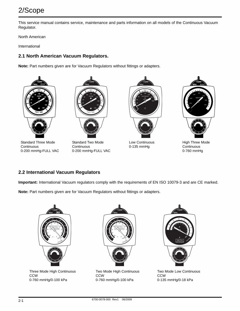
2/ScopeThis service manual contains service, maintenance and parts information on all models of the Continuous VacuumRegulator.
North American
International
2.1 North American Vacuum Regulators.
Note: Part numbers given are for Vacuum Regulators without fittings or adapters.
2.2 International Vacuum Regulators
Important: International Vacuum regulators comply with the requirements of EN ISO 10079-3 and are CE marked.
Note: Part numbers given are for Vacuum Regulators without fittings or adapters.
LOW
MED
HIGH
20
40
6080 100 120
140
160
180
200
-mmHg
FUL L VAC
Low Vacuum
100120
140
160
8060
40
20
mm HgLOW
MED
HIGH
Standard Three ModeContinuous0-200 mmHg-FULL VAC
Low Continuous0-135 mmHg
High Three ModeContinuous0-760 mmHg
Standard Two ModeContinuous0-200 mmHg-FULL VAC
High FlowHigh Vacuum
10
20
30
4050
60
70
80
90
100
100
200
300400
500
600
700
- kPa
-mm Hg
High FlowHigh Vacuum
10
20
30
4050
60
70
80
90
100
100
200
300400
500
600
700
- kPa
-mm Hg
- kPa
-mm
Hg
2
4
68
101214
1618
140
20
40
60
80100
120
20
High FlowLow Vacuum
Two Mode High ContinuousCCW0-760 mmHg/0-100 kPa
Two Mode Low ContinuousCCW0-135 mmHg/0-18 kPa
Three Mode High ContinuousCCW0-760 mmHg/0-100 kPa
2-1
6700-0078-000 Rev1 06/2009
Description and Specification/3
3.1 Description
WARNING Do not use this device in the pres-ence of flammable anesthetics. Staticcharges may not dissipate and a pos-sible explosion hazard exists in thepresence of these agents.
The Continuous Vacuum Regulator is a lightweight, com-pact unit used throughout the hospital primarily for pha-ryngeal/tracheal suctioning (airway management).Various models provide regulated or full-line vacuum forhospital suction procedures.
There are several models of the Continuous VacuumRegulators. All models contain a vacuum gauge whichindicates suction supplied by the regulator. Each has apositive pressure safety relief valve to prevent pressur-ization by either failed injector vacuum (venturi) units orinadvertent cross connection to pressurized gasses. Inaddition, the Low Continuous models include a vacuumrelief valve to limit maximum suction.
Some models operate in a regulated or non-regulated(MAX) mode. Others operate only in the regulated (limit-ed) mode.
In the non-regulated (MAX) mode, the vacuum source isconnected directly to the fitting port. The regulator mod-ule is bypassed and full-line vacuum is provided.
In the regulated (limited) mode, the vacuum source isconnected through the regulator module which functions
as an automatic valve. Turning the suction control knobadjusts the position of the regulator module and allowsselection of a predetermined level of suction when setaccording to instructions.
During use, as the flow requirement increases, the valveautomatically opens to maintain suction at the presetlevel. Conversely, when the flow requirement decreases,the valve automatically closes to maintain suction at thepreset level. The same mechanism compensates forchanges in supply vacuum and automatically maintainsthe pre-set suction level when set according to instruc-tions.
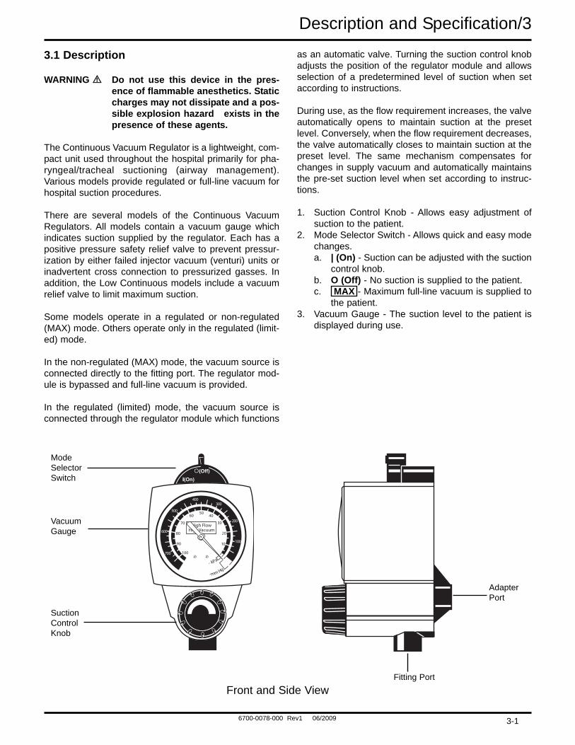
1. Suction Control Knob - Allows easy adjustment ofsuction to the patient.
2. Mode Selector Switch - Allows quick and easy modechanges.a. | (On) - Suction can be adjusted with the suction
control knob.b. O (Off) - No suction is supplied to the patient.c. MAX - Maximum full-line vacuum is supplied to
the patient.3. Vacuum Gauge - The suction level to the patient is
displayed during use.
High FlowHigh Vacuum
10
20
30
4050
60
70
80
90
100
100
200
300400
500
600
700
- kPa
-mm Hg
ModeSelectorSwitch
Front and Side ViewFitting Port
Adapter Port
SuctionControlKnob
VacuumGauge
3-1
6700-0078-000 Rev1 06/2009
3/Description and Specifications
3.2 Specifications
Gauge: Accuracy: ±5% of full scale deflection
Flow Rate: 0 to 80 LPM without fittings at full increase setting depending on supply vacuum and open air flow
Positive Pressure Safety Located in the vacuum supply line to prevent pressurization of the patient connection by Relief Valve: failed injector vacuum (venturi) units, or inadvertent cross connection to pressurized
gases
Ranges: Gauge Range Regulated Suction
Standard Models 0 to 200 mm Hg/0 to 26 kPa 0 to 760 mm Hg/0 to 100 kPaHigh Models 0 to 760 mm Hg/0 to 100 kPa 0 to 760 mm Hg/0 to 100 kPaLow Models 0 to 160 mm Hg/0 to 21 kPa 0 to 135 mm Hg/0 to 18 kPa*
* When measured with an independent measuring device.
Vacuum Relief Valve 140 mm Hg ± 5 mm Hg/18.7 kPa ± 0.7 kPa(Low Vacuum models ONLY):
Weight: 11 oz/312 grams(Less fittings)
WeightLow Vacuum models: 12 oz/340 grams(Less fittings)
Dimensions: Height: 5.7 inches/145 mm(Less fittings) Width: 3.0 inches/76 mm
Depth: 3.8 inches/96 mm
Latex tubing, 0.25 in (6.4 mm) I.D. X 0 to full vacuum12 in (30 cm) supplied: Flow dependent on source and setup
Disposable tubing (Available 0 to full vacuumseparate in some markets; Flow dependent on source and setup6 mm I.D. X 450 mm, 750 mmand 2M) to connect regulatorand collection bottle
Disposable Suction Filter: 0 to full vacuum0 to 100 Lpm @ 650 mmHg (-87 kPa)
Environmental Specifications
Operating Temperature Range: 40oF (4oC) to 120oF (49oC)Storage Temperature Range: 0oF (-18oC) to 150oF (71oC)Operating and Storage Relative Humidity: 5 to 95%
3-2
6700-0078-000 Rev1 06/2009
Operation/4
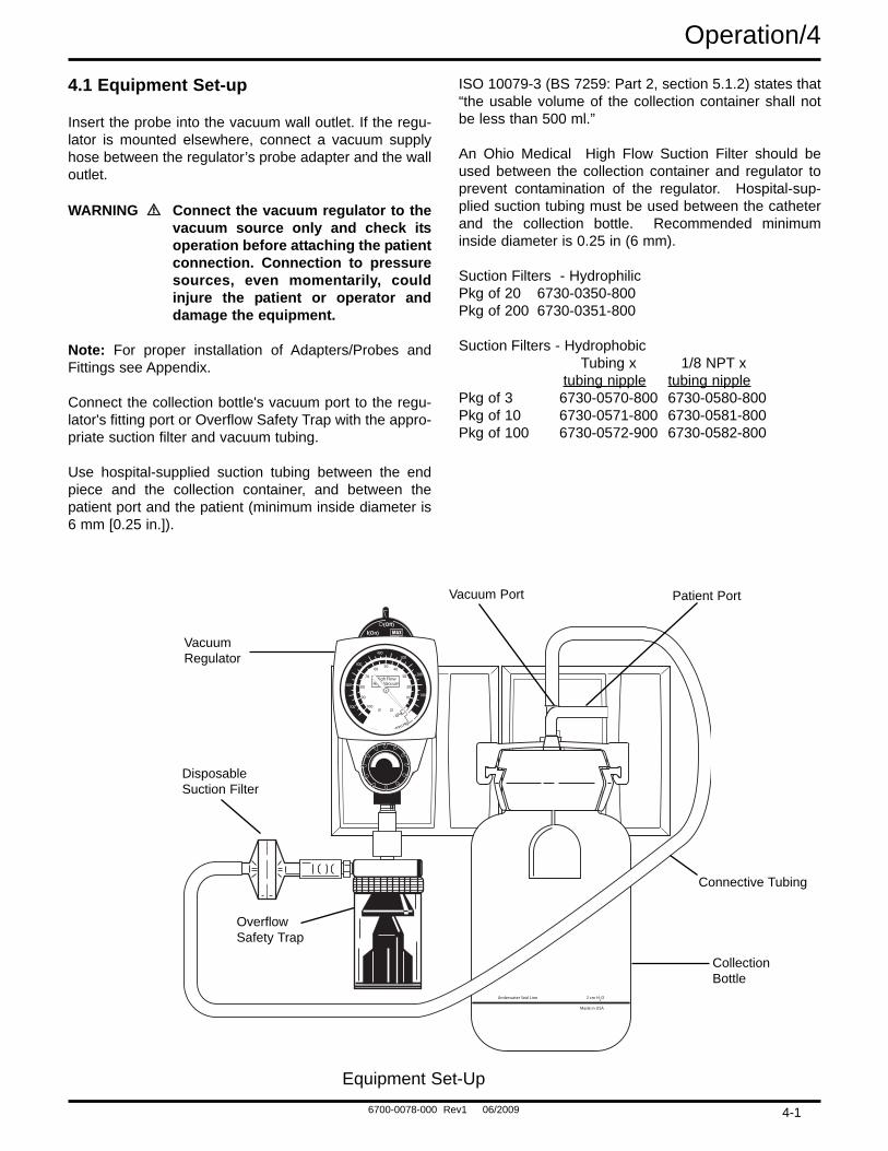
4.1 Equipment Set-up
Insert the probe into the vacuum wall outlet. If the regu-lator is mounted elsewhere, connect a vacuum supplyhose between the regulator’s probe adapter and the walloutlet.
WARNING Connect the vacuum regulator to thevacuum source only and check itsoperation before attaching the patientconnection. Connection to pressuresources, even momentarily, couldinjure the patient or operator anddamage the equipment.
Note: For proper installation of Adapters/Probes andFittings see Appendix.
Connect the collection bottle's vacuum port to the regu-lator's fitting port or Overflow Safety Trap with the appro-priate suction filter and vacuum tubing.
Use hospital-supplied suction tubing between the endpiece and the collection container, and between thepatient port and the patient (minimum inside diameter is6 mm [0.25 in.]).
ISO 10079-3 (BS 7259: Part 2, section 5.1.2) states that“the usable volume of the collection container shall notbe less than 500 ml.”
An Ohio Medical High Flow Suction Filter should beused between the collection container and regulator toprevent contamination of the regulator. Hospital-sup-plied suction tubing must be used between the catheterand the collection bottle. Recommended minimuminside diameter is 0.25 in (6 mm).
Suction Filters - HydrophilicPkg of 20 6730-0350-800Pkg of 200 6730-0351-800
Suction Filters - HydrophobicTubing x 1/8 NPT x
tubing nipple tubing nipplePkg of 3 6730-0570-800 6730-0580-800Pkg of 10 6730-0571-800 6730-0581-800Pkg of 100 6730-0572-900 6730-0582-800
Underwater Seal Line 2 cm H2O
Made in USA
High FlowHigh Vacuum
10
20
30
4050
60
70
80
90
100
100
200
300400
500
600
700
- kPa
-mm Hg
VacuumRegulator
OverflowSafety Trap
Equipment Set-Up
CollectionBottle
Connective Tubing
Patient PortVacuum Port
DisposableSuction Filter
4-1
6700-0078-000 Rev1 06/2009
4/Operation
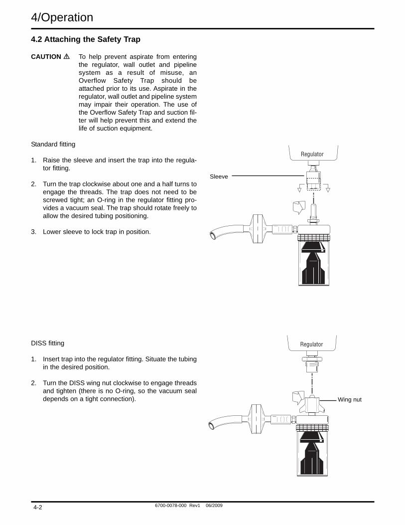
4.2 Attaching the Safety Trap
CAUTION To help prevent aspirate from enteringthe regulator, wall outlet and pipelinesystem as a result of misuse, anOverflow Safety Trap should beattached prior to its use. Aspirate in theregulator, wall outlet and pipeline systemmay impair their operation. The use ofthe Overflow Safety Trap and suction fil-ter will help prevent this and extend thelife of suction equipment.
Standard fitting
1. Raise the sleeve and insert the trap into the regula-tor fitting.
2. Turn the trap clockwise about one and a half turns toengage the threads. The trap does not need to bescrewed tight; an O-ring in the regulator fitting pro-vides a vacuum seal. The trap should rotate freely toallow the desired tubing positioning.
3. Lower sleeve to lock trap in position.
DISS fitting
1. Insert trap into the regulator fitting. Situate the tubingin the desired position.
2. Turn the DISS wing nut clockwise to engage threadsand tighten (there is no O-ring, so the vacuum sealdepends on a tight connection).
Sleeve
Wing nut
4-2
6700-0078-000 Rev1 06/2009
Operation/4
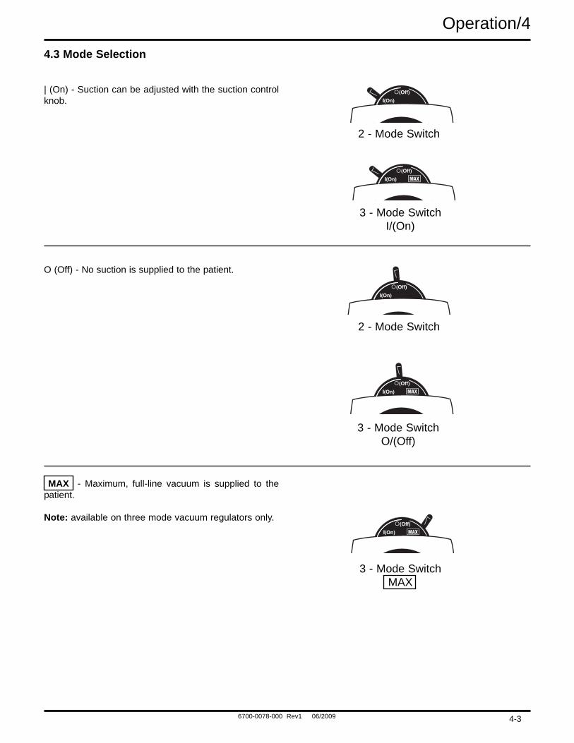
4.3 Mode Selection
| (On) - Suction can be adjusted with the suction controlknob.
O (Off) - No suction is supplied to the patient.
MAX - Maximum, full-line vacuum is supplied to thepatient.
Note: available on three mode vacuum regulators only.
2 - Mode Switch
3 - Mode SwitchI/(On)
2 - Mode Switch
3 - Mode SwitchO/(Off)
3 - Mode SwitchMAX
4-3
6700-0078-000 Rev1 06/2009
4/Operation
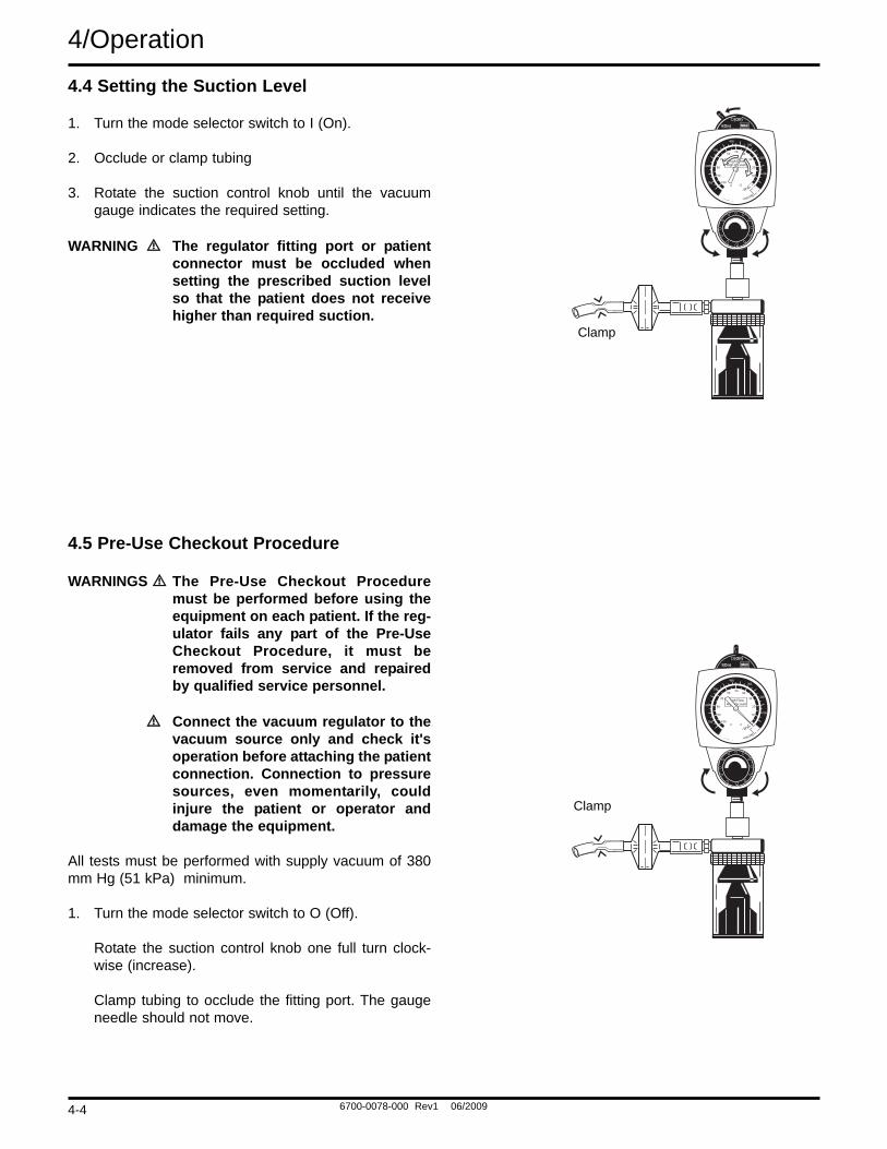
4.4 Setting the Suction Level
1. Turn the mode selector switch to I (On).
2. Occlude or clamp tubing
3. Rotate the suction control knob until the vacuumgauge indicates the required setting.
WARNING The regulator fitting port or patientconnector must be occluded whensetting the prescribed suction levelso that the patient does not receivehigher than required suction.
4.5 Pre-Use Checkout Procedure
WARNINGS The Pre-Use Checkout Proceduremust be performed before using theequipment on each patient. If the reg-ulator fails any part of the Pre-UseCheckout Procedure, it must beremoved from service and repairedby qualified service personnel.
Connect the vacuum regulator to thevacuum source only and check it'soperation before attaching the patientconnection. Connection to pressuresources, even momentarily, couldinjure the patient or operator anddamage the equipment.
All tests must be performed with supply vacuum of 380mm Hg (51 kPa) minimum.
1. Turn the mode selector switch to O (Off).
Rotate the suction control knob one full turn clock-wise (increase).
Clamp tubing to occlude the fitting port. The gaugeneedle should not move.
High FlowHigh Vacuum
10
20
30
4050
60
70
80
90
100
100
200
300400
500
600
700
- kPa
-mm Hg
Clamp
High FlowHigh Vacuum
10
20
30
4050
60
70
80
90
100
100
200
300400
500
600
700
- kPa
-mm Hg
Clamp
4-4
6700-0078-000 Rev1 06/2009
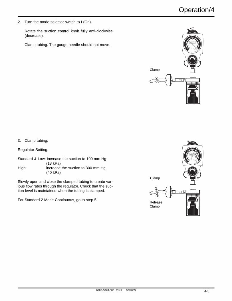
Operation/42. Turn the mode selector switch to I (On).
Rotate the suction control knob fully anti-clockwise(decrease).
Clamp tubing. The gauge needle should not move.
3. Clamp tubing.
Regulator Setting
Standard & Low: increase the suction to 100 mm Hg (13 kPa)
High: increase the suction to 300 mm Hg (40 kPa)
Slowly open and close the clamped tubing to create var-ious flow rates through the regulator. Check that the suc-tion level is maintained when the tubing is clamped.
For Standard 2 Mode Continuous, go to step 5.
High FlowHigh Vacuum
10
20
30
4050
60
70
80
90
100
100
200
300400
500
600
700
- kPa
-mm Hg
High FlowHigh Vacuum
10
20
30
4050
60
70
80
90
100
100
200
300400
500
600
700
- kPa
-mm Hg
Clamp
Clamp
ReleaseClamp
4-5
6700-0078-000 Rev1 06/2009
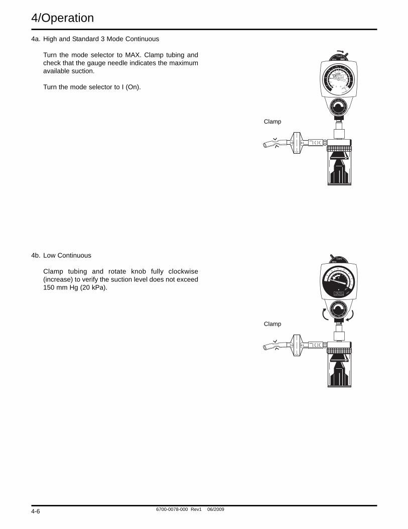
4/Operation4a. High and Standard 3 Mode Continuous
Turn the mode selector to MAX. Clamp tubing andcheck that the gauge needle indicates the maximumavailable suction.
Turn the mode selector to I (On).
4b. Low Continuous
Clamp tubing and rotate knob fully clockwise(increase) to verify the suction level does not exceed150 mm Hg (20 kPa).
High FlowHigh Vacuum
10
20
30
4050
60
70
80
90
100
100
200
300400
500
600
700
- kPa
-mm Hg
- kPa
-mmHigh Flow
Low Vacuum
2
4
68
101214
1618
140
20
40
60
80100
120
20
Clamp
Clamp
4-6
Underwater Seal Line 2 cm H2O
Made in USA
High FlowHigh Vacuum
10
20
30
4050
60
70
80
90
100
100
200
300400
500
600
700
- kPa
-mm Hg
6700-0078-000 Rev1 06/2009
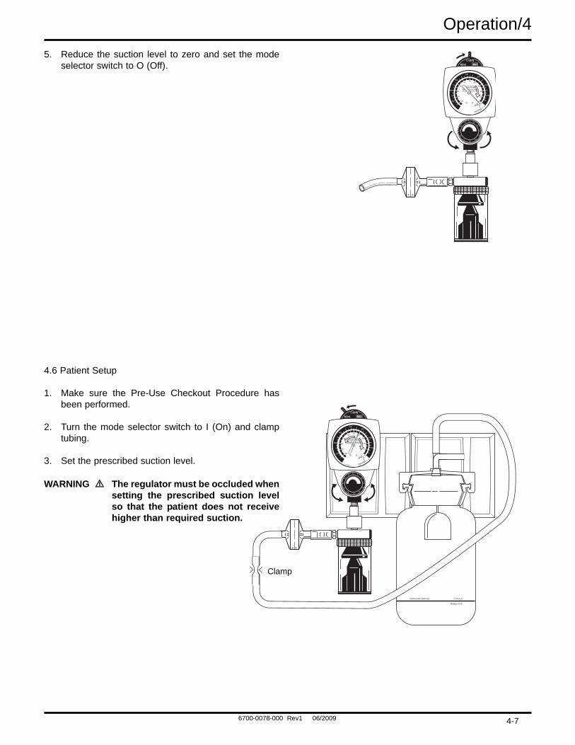
Operation/45. Reduce the suction level to zero and set the mode
selector switch to O (Off).
4.6 Patient Setup
1. Make sure the Pre-Use Checkout Procedure hasbeen performed.
2. Turn the mode selector switch to I (On) and clamptubing.
3. Set the prescribed suction level.
WARNING The regulator must be occluded whensetting the prescribed suction levelso that the patient does not receivehigher than required suction.
High FlowHigh Vacuum
10
20
30
4050
60
70
80
90
100
100
200
300400
500
600
700
- kPa
-mm Hg
Clamp
4-7

Underwater Seal Line 2 cm H2O
Made in USA
High FlowHigh Vacuum
10
20
30
4050
60
70
80
90
100
100
200
300400
500
600
700
- kPa
-mm Hg
6700-0078-000 Rev1 06/2009
4/Operation4. Turn the mode selector switch to O (Off).
5. Attach tubing to the vacuum port of the collectioncontainer.
6. Turn the mode selector switch to I (On).Important: The Low models do notdeliver suction in excess of 150mm Hg (20 kPa).
PatientConnectiveTubing
Underwater Seal Line 2 cm H2O
Made in USA
High FlowHigh Vacuum
10
20
30
4050
60
70
80
90
100
100
200
300400
500
600
700
- kPa
-mm Hg
4-8

6700-0078-000 Rev1 06/2009
Cleaning and Sterilization/5
5.1 Cleaning
WARNING After patient use, regulators may becontaminated. Handle in accordancewith your hospital’s infection controlpolicy.
5.1.1 Routine Exterior Cleaning
Routine cleaning of the regulator is recommended as astandard procedure after each use.
Wipe all exterior surfaces with a solution of water andmild detergent.
5.1.2 Internal Component Cleaning
CAUTION Cleaning the gauge may result in damage.
The regulator requires cleaning if it becomes flooded withpatient fluid as a result of misuse.
1. Refer to the Service - Disassembly and Assemblyinstructions.
2. All internal components, with the exception of thegauge, may be cleaned with a solution of warm waterand mild detergent, preferably an enzymatic cleaner.
3. Dry all components with a lint free cloth beforeassembly.
5.2 SterilizationShould misuse occur, resulting in accidental flooding ofthe regulator, the regulator may be sterilized usingEthylene Oxide (ETO). After sterilization, follow the serv-ice checkout procedures in Section 8.
WARNING Following sterilization with ethyleneoxide, parts should be quarantined ina well ventilated area to allow dissipa-tion of residual ethylene oxide gas
absorbed by the material. Aerateparts for 8 hours at 130oF (54oC).
CAUTION Do not steam autoclave or liquid sterilizethe Continuous Vacuum Regulator.Severe impairment to the operation ofthe regulator will result. The only accept-able method of sterilization is with gas(ethylene oxide).
CAUTION Sterilization with ethylene oxide mix-tures may cause crazing (minute super-ficial cracking) of some plastic parts.Crazing will be more pronounced whenmixtures containing Freon® are used.
Note: The Vacuum Regulator should only be sterilized ifit is contaminated or maintenance is to be performed.
1. The regulator should be sterilized with the modeselector switch in the | (On) position.
2. The only acceptable method of sterilization is withethylene oxide. Ethylene oxide mixtures can be usedat temperatures of 125 to 135 °F (52 - 57 °C). If thistemperature cannot be obtained, room temperaturesterilization with 100% ethylene oxide can also beused. Sterilization is not recommended as a stan-dard procedure after each use.
3. After each sterilization, check the condition of theinternal filter. If the filter appears to have shrunk,replace it before placing the regulator back in serv-ice.
4. Adequately aerate the regulator prior to disassembly,shipment or use. Aerate parts prior to reassembly.
®Freon is a registered trademark of the DuPont Company.
5-1

6700-0078-000 Rev1 06/2009
6/TroubleshootingProblem
A. No gauge indication and no suc-tion in any setting
B. No gauge indication but suctionis being delivered
C. Gauge indication but no suctionis being delivered
D. Suction level cannot be adjusted
E. Insufficient flow through regula-tor
Possible Causes
1. No supply vacuum
2. Kinked tube
3. Poor connection
4. Blocked adapter port
5. Blocked backplate
6. Blocked adapter
7. Blocked wall outlet
1. Blocked gauge pressure sensingorifice
2. Gauge mechanism locked bydebris
3. Gauge mechanism damaged
1. Blocked fitting port
2. Overflow Safety Trap shut-off
3. Blocked external filter
4. Blocked fitting
1. Mode selector switch in MAXposition
2. Regulator module small o-ringfailure
3. Regulator module diaphragmrupture
4. Regulator module stem screwloose
1. Partial blockage in wall supply
2. Partial blockage in regulator
Remedy
1. Correct supply problems
2. Straighten tube
3. Check all connections and seals
4. Unblock port
5. Clean with soap and water andpipe cleaner
6. Replace adapter
7. Unblock outlet
1. Clean or replace gauge
2. Clean or replace gauge
3. Replace gauge
1. Clean port
2. Reset flow and/or empty trap
3. Replace filter
4. Clean fitting
1. Switch to I(On)
2. Replace rubber components withregulator module replacement kit
3. Replace rubber components withregulator module replacement kit
4. Tighten stem screw
1a. Confirm wall supply open air flowmeets minimum hospital require-ments
1b. Unblock if necessary
2a. Perform the Flow Test in theService Checkout ProcedureSection of this manual
2b. Clear blockage if necessary
6-1

6700-0078-000 Rev1 06/2009
Troubleshooting/6Problem
F. Inaccurate gauge reading
Note: All gauge needles shouldcome to rest within the zerorange bracket or return to thestop pin when no suction isbeing supplied.
G. With the fitting port occluded,unable to decrease the suctionlevel and gauge needle does notreturn to zero when switched toO (Off)
H. No suction in any setting andwhistling noise from inside theregulator
Possible Causes
1. Damaged gauge
1. Blocked filter and/or orifice
2. Damaged gauge
1. Positive pressure safety reliefvalve failure
2. Vacuum relief valve failure (lowmodels ONLY)
Remedy
1. Replace gauge
1. Clear orifice and replace filter
2. Replace gauge
1. Replace positive pressure safe-ty relief valve
2. Replace o-ring and ensure thatthe steel ball is present andclean
6-2
6700-0078-000 Rev1 06/2009
7/Service - Disassembly and Assembly
7.1 Service Tools and Equipment
CAUTION Use of lubricants other than recom-mended may degrade plastic or rubbercomponents.
The following items should be on hand during any serv-ice procedure.
• Supply vacuum: 500 mm Hg/ ± 10 mmHg (67 kPa ±1.3 kPa) & 50 LPM open air flow minimum
• Supply Vacuum Regulator with Gauge, 760 mm Hg(101.3 kPa) Full Scale.
• Low Vacuum Calibration Gauge, 225 mm Hg (30kPa) Full Scale* (Ohio Medical P/N 6700-0353-800)
• High Vacuum Calibration Gauge, 760 mm Hg (101.3kPa) Full Scale*(Ohio Medical P/N 6700-0352-800)
• 50 LPM Flowmeter (Ohio Medical P/N 6700-0355-800)
• Hexagonal Allen Wrench 3/32 inch
• Phillips Head Screwdriver, No. 2
• Flat Head Screwdriver, 1/4 inch
• Pliers
• Dow® 111 Grease (Ohio Medical P/N 6700-0074-200)
• Loctite® 242 Removable Thread Locker (OhioMedical P/N 0220-5016-300)
• Tubing Clamp
• Bubble Leak Tester
• Tweezers (Filter Remover)
• Wooden Tooth Pick (O-ring Remover)
• Pipe Cleaner
(*) Accuracy: ±1% of full scale deflection
®Dow is a registered trademark of the Dow Chemical Corporation
7.2 Continuous Vacuum Regulators (AllModels)
7.2.1 Disassembly
WARNINGS If the Vacuum Regulator is repairedor disassembled in any manner, theService Checkout Procedure must beperformed before using the equip-ment on a patient.
Clean and sterilize all suction equip-ment if contaminated before disas-sembly, to ensure service personnelare not exposed to hazardous con-tamination.
When servicing a Low VacuumRegulator, perform the Vacuum ReliefValve Adjustment and Low VacuumLimit Setting Procedure.
CAUTION The gauge assembly must be handledwith utmost care to retain its precision. Ifthe lens is removed, do not rest thegauge on its face.
7-1
6700-0078-000 Rev1 06/2009
Service - Disassembly and Assembly/7
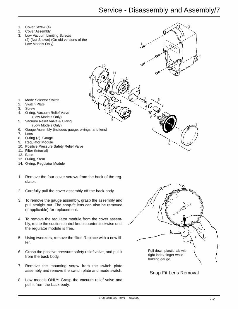
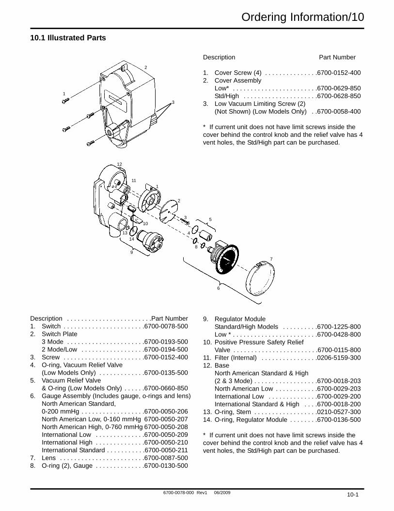
1. Cover Screw (4)2. Cover Assembly3. Low Vacuum Limiting Screws
(2) (Not Shown) (On old versions of the Low Models Only)
1. Mode Selector Switch2. Switch Plate3. Screw4. O-ring, Vacuum Relief Valve
(Low Models Only)5. Vacuum Relief Valve & O-ring
(Low Models Only)6. Gauge Assembly (includes gauge, o-rings, and lens)7. Lens8. O-ring (2), Gauge9. Regulator Module10. Positive Pressure Safety Relief Valve11. Filter (Internal)12. Base13. O-ring, Stem14. O-ring, Regulator Module
1. Remove the four cover screws from the back of the reg-ulator.
2. Carefully pull the cover assembly off the back body.
3. To remove the gauge assembly, grasp the assembly andpull straight out. The snap-fit lens can also be removed(if applicable) for replacement.
4. To remove the regulator module from the cover assem-bly, rotate the suction control knob counterclockwise untilthe regulator module is free.
5. Using tweezers, remove the filter. Replace with a new fil-ter.
6. Grasp the positive pressure safety relief valve, and pull itfrom the back body.
7. Remove the mounting screw from the switch plateassembly and remove the switch plate and mode switch.
8. Low models ONLY: Grasp the vacuum relief valve andpull it from the back body.
Pull down plastic tab withright index finger whileholding gauge
Snap Fit Lens Removal
7-2
1
2
1
12
11
1
1413
9
3
4
8
5
6
7
3
2
6700-0078-000 Rev1 06/2009
7/Service - Disassembly and Assembly7.2.2 Assembly
CAUTION To prevent stripping the plastic threads,place the screw in the hole and turncounterclockwise until it drops into theoriginal thread. Tighten screw.
1. Place the positive pressure safety relief valve in posi-tion and push onto the back body.
2. Low models ONLY: Lubricate the vacuum relief valveO-ring and install it in the valve housing.
3. Lubricate the switch gasket surface with a thin coat-ing of Dow 111 Grease. Place the mode switch onthe base with the arrow at 12 o’clock. Place theswitch plate onto the switch so that the OFF/O isunder the arrow. Install and tighten the mountingscrew. Test the mode switch at all positions.
4. Place the internal filter into the proper cavity andpush until it hits the bottom of the base.
5. Place the regulator module into the cover with thescrew thread facing the knob. Align the protrudingears at 3 and 9 o’clock and rotate the suction controlknob clockwise until the threads engage.
6. Install the snap-fit lens by placing one of the retain-ing tabs over the edge of the gauge face, and thenpressing lightly until the other tab snaps onto thegauge face. Rotate the lens to confirm proper instal-lation.
7. Install the gauge assembly by lubricating the gaugeo-rings with a thin coating of Dow 111 Grease andpushing the gauge into the base mount. Ensure thatthe gauge is properly aligned.
8. Place the cover assembly onto the base and pushtogether until the base and back of the cover areflush.
9. Install the 4 cover screws.
7.3Suction Level Limit Setting-Low Models ONLY
WARNING This Low Vacuum Limit SettingProcedure must be followed whenrepairing Low Vacuum Regulators.Failure to do this may result in suc-tion exceeding the prescribed level.
The design of the low continuous vacuum regulator hasbeen changed to eliminate the low vacuum limiting setscrews located inside the cover behind the suction con-trol knob. The vacuum relief valve has also beenchanged to limit the vacuum to the same level as the setscrews did. This new vacuum relief valve has four ventholes; the old valve had two. If a new cover is used, anew vacuum relief valve must be used.
Versions with limiting screws have two means of limitingthe suction level:
1. Low vacuum limiting screws in the cover; these canbe set at 140 mmHg/19 kPa (± 10 mmHg/1.0 kPa).
2. Vacuum relief valve; this can be set at 165 mmHg ±15 mmHg (22 kPa ± 2 kPa).
These vacuum limit settings may be reduced toaccommodate user requirements. If the vacuum limitsettings are reduced, the vacuum relief valve mustbe set 25 mmHg ± 15 mmHg (3 kPa ± 2 kPa) higherthan the vacuum limiting screws.
Versions without the limiting screws use only the reliefvalve to limit the suction level. The relief valve can be setat 140 mmHg ± 5 mmHg (18.7 kPa ± 0.7 kPa).
7-3
6700-0078-000 Rev1 06/2009
Service - Disassembly and Assembly/7
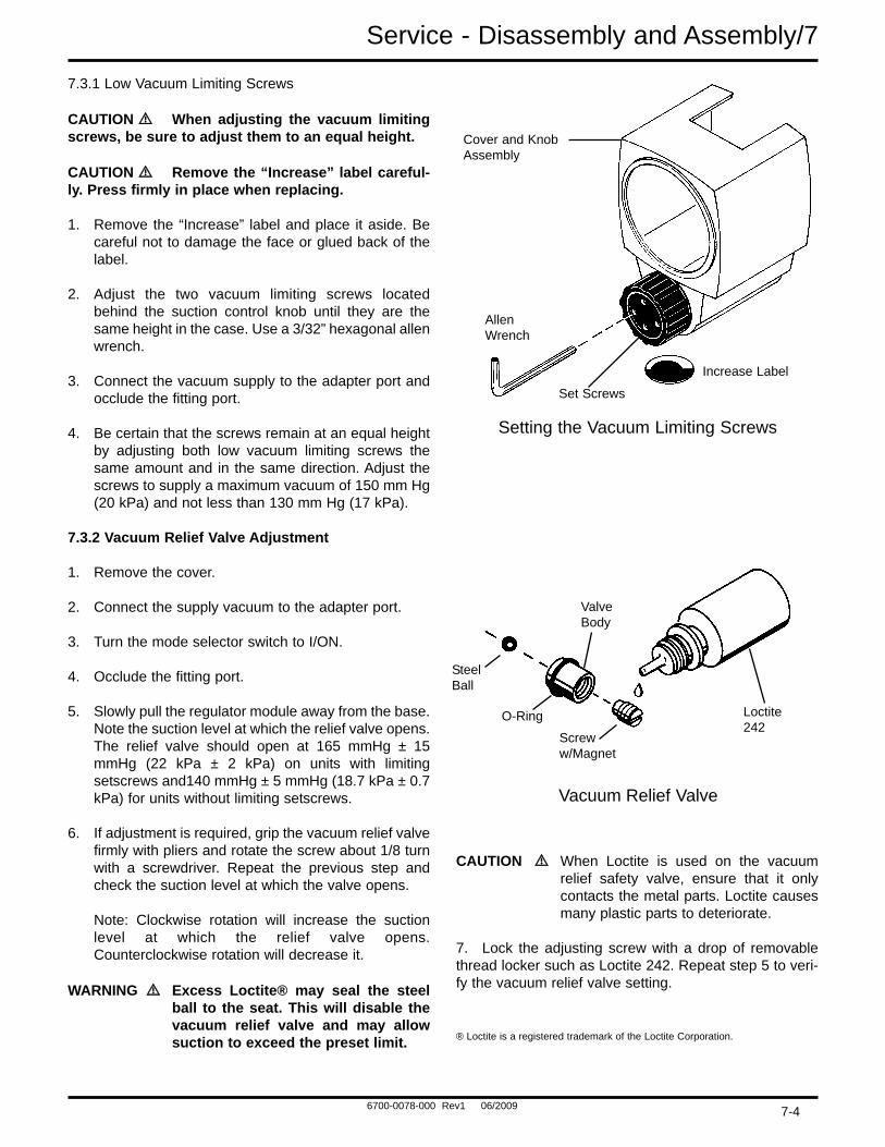
7.3.1 Low Vacuum Limiting Screws
CAUTION When adjusting the vacuum limitingscrews, be sure to adjust them to an equal height.
CAUTION Remove the “Increase” label careful-ly. Press firmly in place when replacing.
1. Remove the “Increase” label and place it aside. Becareful not to damage the face or glued back of thelabel.
2. Adjust the two vacuum limiting screws locatedbehind the suction control knob until they are thesame height in the case. Use a 3/32” hexagonal allenwrench.
3. Connect the vacuum supply to the adapter port andocclude the fitting port.
4. Be certain that the screws remain at an equal heightby adjusting both low vacuum limiting screws thesame amount and in the same direction. Adjust thescrews to supply a maximum vacuum of 150 mm Hg(20 kPa) and not less than 130 mm Hg (17 kPa).
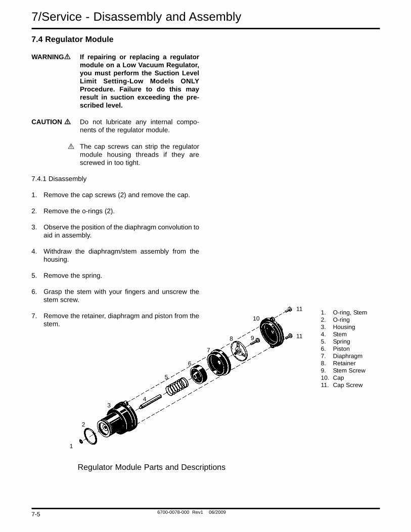
7.3.2 Vacuum Relief Valve Adjustment
1. Remove the cover.
2. Connect the supply vacuum to the adapter port.
3. Turn the mode selector switch to I/ON.
4. Occlude the fitting port.
5. Slowly pull the regulator module away from the base.Note the suction level at which the relief valve opens.The relief valve should open at 165 mmHg ± 15mmHg (22 kPa ± 2 kPa) on units with limitingsetscrews and140 mmHg ± 5 mmHg (18.7 kPa ± 0.7kPa) for units without limiting setscrews.
6. If adjustment is required, grip the vacuum relief valvefirmly with pliers and rotate the screw about 1/8 turnwith a screwdriver. Repeat the previous step andcheck the suction level at which the valve opens.
Note: Clockwise rotation will increase the suctionlevel at which the relief valve opens.Counterclockwise rotation will decrease it.
WARNING Excess Loctite® may seal the steelball to the seat. This will disable thevacuum relief valve and may allowsuction to exceed the preset limit.
CAUTION When Loctite is used on the vacuumrelief safety valve, ensure that it onlycontacts the metal parts. Loctite causesmany plastic parts to deteriorate.
7. Lock the adjusting screw with a drop of removablethread locker such as Loctite 242. Repeat step 5 to veri-fy the vacuum relief valve setting.
® Loctite is a registered trademark of the Loctite Corporation.
Cover and KnobAssembly
AllenWrench
Set Screws
Increase Label
Setting the Vacuum Limiting Screws
Vacuum Relief Valve
ValveBody
SteelBall
O-Ring
Screww/Magnet
Loctite242
7-4
6700-0078-000 Rev1 06/2009
7.4 Regulator Module
WARNING If repairing or replacing a regulatormodule on a Low Vacuum Regulator,you must perform the Suction LevelLimit Setting-Low Models ONLYProcedure. Failure to do this mayresult in suction exceeding the pre-scribed level.
CAUTION Do not lubricate any internal compo-nents of the regulator module.
The cap screws can strip the regulatormodule housing threads if they arescrewed in too tight.
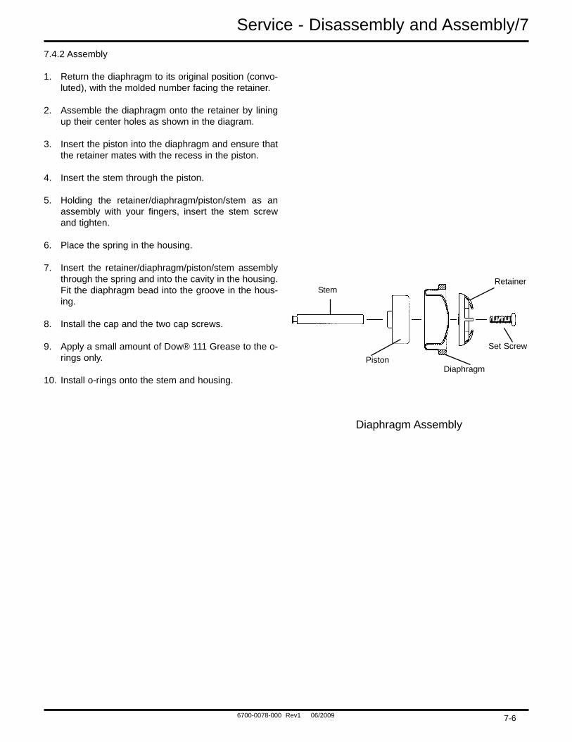
7.4.1 Disassembly
1. Remove the cap screws (2) and remove the cap.
2. Remove the o-rings (2).
3. Observe the position of the diaphragm convolution toaid in assembly.
4. Withdraw the diaphragm/stem assembly from thehousing.
5. Remove the spring.
6. Grasp the stem with your fingers and unscrew thestem screw.
7. Remove the retainer, diaphragm and piston from thestem.
7/Service - Disassembly and Assembly
1. O-ring, Stem2. O-ring3. Housing4. Stem5. Spring6. Piston7. Diaphragm8. Retainer9. Stem Screw10. Cap11. Cap Screw
1
11
1110
98
7
6
5
43
2
Regulator Module Parts and Descriptions
7-5
6700-0078-000 Rev1 06/2009
Service - Disassembly and Assembly/77.4.2 Assembly
1. Return the diaphragm to its original position (convo-luted), with the molded number facing the retainer.
2. Assemble the diaphragm onto the retainer by liningup their center holes as shown in the diagram.
3. Insert the piston into the diaphragm and ensure thatthe retainer mates with the recess in the piston.
4. Insert the stem through the piston.
5. Holding the retainer/diaphragm/piston/stem as anassembly with your fingers, insert the stem screwand tighten.
6. Place the spring in the housing.
7. Insert the retainer/diaphragm/piston/stem assemblythrough the spring and into the cavity in the housing.Fit the diaphragm bead into the groove in the hous-ing.
8. Install the cap and the two cap screws.
9. Apply a small amount of Dow® 111 Grease to the o-rings only.
10. Install o-rings onto the stem and housing.
Diaphragm Assembly
StemRetainer
Set Screw
DiaphragmPiston
7-6
6700-0078-000 Rev1 06/2009
8/Service Checkout Procedure
WARNING If the Vacuum Regulator is repaired ordisassembled in any manner, theService Checkout Procedure must beperformed before using the equip-ment on a patient.
Important: This entire Service Checkout Proceduremust be performed in numerical order.
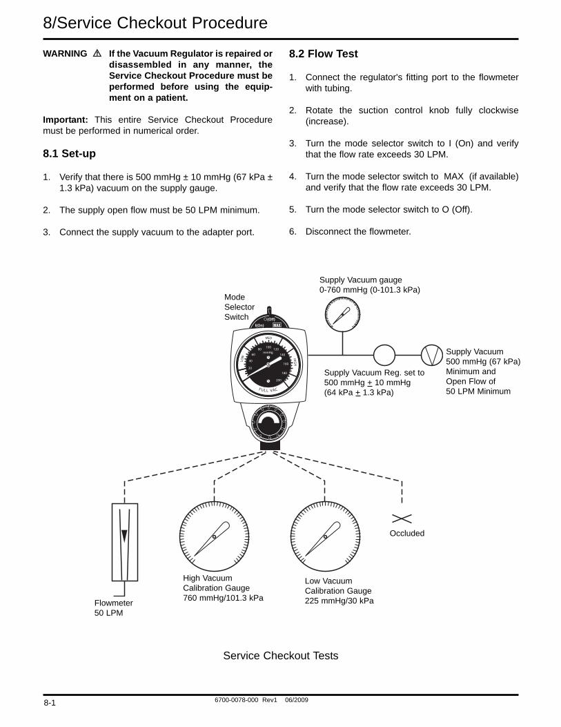
8.1 Set-up
1. Verify that there is 500 mmHg ± 10 mmHg (67 kPa ±1.3 kPa) vacuum on the supply gauge.
2. The supply open flow must be 50 LPM minimum.
3. Connect the supply vacuum to the adapter port.
8.2 Flow Test
1. Connect the regulator's fitting port to the flowmeterwith tubing.
2. Rotate the suction control knob fully clockwise(increase).
3. Turn the mode selector switch to I (On) and verifythat the flow rate exceeds 30 LPM.
4. Turn the mode selector switch to MAX (if available)and verify that the flow rate exceeds 30 LPM.
5. Turn the mode selector switch to O (Off).
6. Disconnect the flowmeter.LO
W
MED
HIGH
20
40
6080 100 120
140
160
180
200
mmHg
F UL L VAC
ModeSelectorSwitch
Supply Vacuum gauge0-760 mmHg (0-101.3 kPa)
Supply Vacuum Reg. set to500 mmHg + 10 mmHg(64 kPa + 1.3 kPa)
Supply Vacuum500 mmHg (67 kPa)Minimum andOpen Flow of50 LPM Minimum
Occluded
Low VacuumCalibration Gauge225 mmHg/30 kPa
High VacuumCalibration Gauge760 mmHg/101.3 kPaFlowmeter
50 LPM
Service Checkout Tests
8-1
6700-0078-000 Rev1 06/2009
Service Check Out Procedure/8
8.3 Gauge Test
Note: All Ohio Medical gauges are supplied with an accu-racy of ±5% of full scale deflection throughout theirrange. The table below is provided for reference.
Gauge Range ToleranceStandard 0-200 mmHg (0-26 kPa) ±10 mmHg (1.3 kPa)
VacuumLow 0-160 mmHg (0-20 kPa) ±8 mmHg (1.1 kPa)
VacuumHigh 0-760 mmHg (0-100 kPa) ±38 mmHg (5 kPa)
Vacuum
Note: All gauge needles should come to rest within thezero range bracket or return to the stop pin when no suc-tion is being supplied. Gauges which do not comply maybe out of calibration.
When checking gauge accuracy, be sure that the calibra-tion gauge has an accuracy of 1% of full scale deflectionor better.
8.3.1 High Vacuum Gauges ONLY
1. Connect the regulator's fitting port to the high calibra-tion gauge with tubing.
2. Turn the mode selector switch to I (On).
3. Assure that the gauge is in agreement with the highvacuum calibration gauge within the ±38 mmHg (5kPa) tolerance. Recommended test points are 100,300, and 500mm Hg.
8.3.2 Standard and Low Vacuum Gauges ONLY
1. Connect the regulator's fitting port to the low calibra-tion gauge with tubing.
2. Turn the mode selector switch to I (On).
3. Assure that the gauge is in agreement with the lowvacuum calibration gauge within the ±10 mmHg (1.3kPa) or the ±8 mmHg (1.1 kPa) tolerance for stan-dard and low gauges respectively. Recommendedtest points are 40, 80, and 140 mmHg.
4. For the Standard Gauge ONLY: Rotate the suctioncontrol knob fully clockwise (increase) and verify itsreading is in the FULL VAC range.
8.4 Regulation Test
1. Disconnect the calibration gauge and occlude the fit-ting port.
2. If using a High Vacuum Regulator, set its gauge to300 mmHg (40 kPa). If using a Low or StandardVacuum Regulator, set its gauge to 100 mmHg/14kPa.
3. Open and close the fitting port several times.
4. With the fitting port occluded, the gauge shouldreturn to the setting listed in step 2 within a toleranceof:±38 mmHg (5 kPa) for high vacuum gauge
or
±10 mmHg (1.3 kPa) for the standard vacuum gauges
or
±8mmHg (1.1 kPa) for the low vacuum gauge.
8.5 Low Vacuum Regulators ONLY
1. Occlude the fitting port.
2. Rotate the suction control knob fully clockwise(increase).
3. Verify that the suction delivered does not exceed 150mm Hg (20 kPa) or the maximum suction requestedby the clinician.
Note: For setting the Suction level limit, refer toSuction Level Limit Setting-Low Models ONLY.
8.6 Bleed Test
1. Occlude the fitting port and set the vacuum level to100 mm Hg (14 kPa).
2. Turn the selector switch to O (Off) and observe thegauge needle. It must return to the zero range brack-et or stop pin within 10 seconds.
8-2
6700-0078-000 Rev1 06/2009
8/Service Checkout Procedure
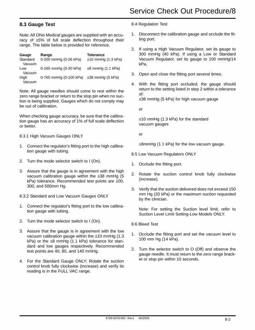
8.7 Leak Test - Supply Side
1. Connect the supply vacuum tubing to port “A” of the Bubble Leak Tester.
2. Connect port “B” of the Bubble Leak Tester to the regulator adapter port.
3. Turn the mode selector switch to O (Off). Allow the fitting port to be open to air.
4. Wait 20 seconds. No More than 6 bubbles should appear in the next ten seconds.
Important: Prior to venting port "A" of the Bubble Leak Tester to atmosphere (i.e. turning the supply regulator off),ensure the tubing from port "B" has been disconnected from the adapter port of the vacuum regulator.
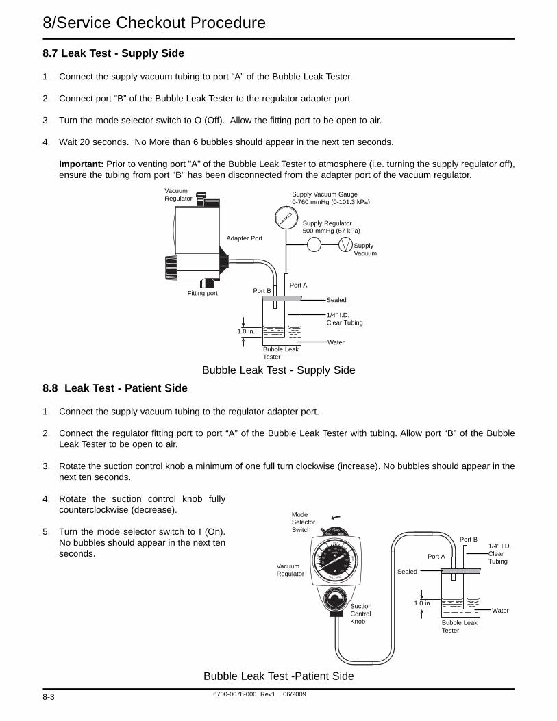
8.8 Leak Test - Patient Side
1. Connect the supply vacuum tubing to the regulator adapter port.
2. Connect the regulator fitting port to port “A” of the Bubble Leak Tester with tubing. Allow port “B” of the BubbleLeak Tester to be open to air.
3. Rotate the suction control knob a minimum of one full turn clockwise (increase). No bubbles should appear in thenext ten seconds.
4. Rotate the suction control knob fullycounterclockwise (decrease).
5. Turn the mode selector switch to I (On).No bubbles should appear in the next tenseconds.
Supply Vacuum Gauge0-760 mmHg (0-101.3 kPa)
Bubble LeakTester
1/4” I.D.Clear Tubing
SealedPort B
Port A
1.0 in.
Fitting port
Adapter Port
VacuumRegulator
SupplyVacuum
Supply Regulator500 mmHg (67 kPa)
Water
Bubble Leak Test - Supply Side
LOW
MED
HIGH
20
40
6080 100 120
140
160
180
200
mmHg
F UL L VAC
ModeSelector Switch
1.0 in.
Bubble LeakTester
Water
1/4” I.D. ClearTubing
Port B
Port A
Sealed
SuctionControlKnob
VacuumRegulator
Bubble Leak Test -Patient Side
8-3
6700-0078-000 Rev1 06/2009
Maintenance/9WARNING The Pre-Use Checkout Procedure
must be performed before using thisequipment on each patient. If the reg-ulator fails any part of the Pre-UseCheckout Procedure, it must beremoved from service and repairedby qualified service personnel.
WARNING Clean and sterilize all suction equip-ment if contaminated before disas-sembly, to ensure service personnelare not exposed to hazardous con-tamination.
Continuous Vacuum Regulators should be kept inuse or used on a rotating basis.Unused equipment may tend to dete-riorate.
Maintenance of the vacuum piping system is as impor-tant as maintenance of the suction equipment. The useof Collection Bottles with reliable shut-off valves,Overflow Safety Trap assemblies and disposable suctionfilters will protect the regulator and piping system. Theflow rate at the wall outlet should be checked on a year-ly basis and suitable cleaning of the outlets should beperformed. The flow rate measurement should meetlocal standards.
Routine maintenance and inspection are important to theperformance of suction equipment. The following is arecommended list for care of suction equipment aftereach patient use.
1. Perform a thorough cleaning by washing all bottles,tubing, metal connectors, etc, and removing allresidue.
2. Wipe all exterior surfaces with a solution of waterand mild detergent.
3. Perform a careful visual inspection.
4. Check that the High Flow Disposable Suction Filter is clean and in good condition.
5. Check that all tubing is in good condition and con-nected securely to the correct ports.
6. Check the floats in the Overflow Safety Trap andCollection Bottle for correct operation.
7. Perform the Pre-Use Checkout Procedure.
9.2 Recommended Maintenance Schedule
In addition to the Pre-Use Checkout Procedure, the following periodic maintenance should be performed.9.2.1 Maintenance Schedule
Item Minimum Frequency Comments
Service Checkout Every 12 months If the regulator does not pass the Procedure Service Checkout Procedure,refer to the Troubleshooting section ofthis manual. Repair as necessary.
Elastometric As Required Cleaning and replacement intervalComponents,O-rings, will depend greatly on hours of usage and switch gasket, environmental conditions. Replace and reg. module diaphragm, repair as necessary.positive pressure safety valve) and Internal Filter
9-1

6700-0078-000 Rev1 06/2009
9/Maintenance
9.3 Repair Policy
WARNING Clean and sterilize all suction equip-ment before shipment or service toensure transportation personneland/or service personnel are notexposed to any hazardous contami-nation.
CAUTIONS Do not steam autoclave or liquid sterilizethe Continuous Vacuum Regulator.Severe impairment to the operation ofthe regulator will result. The only accept-able method of sterilization is with gas(ethylene oxide).
Only competent individuals trained in therepair of this equipment should attemptto service it.
Do not use malfunctioning equipment. Make all neces-sary repairs. Have the equipment repaired by qualifiedservice personnel or by Ohio Medical. Parts listed in theservice manual for this product may be repaired orreplaced by a competent, trained person who has expe-rience in repairing devices of this nature. After repair, per-form the Service Checkout Procedure to ensure that it isfunctioning properly, and complies with the publishedspecifications.
9.4 Technical Assistance
If technical assistance is required, contact Ohio Medicaltechnical support or field operations listed on the backcover.
9.5 Return Instructions
1. Call 866-549-6446 for a returned goods authoriza-tion.
2. Clean and sterilize the Vacuum Regulator.
3. Package the Vacuum Regulator securely for protec-tion; preferably in the original container.
4. Include a letter describing in detail any difficultiesexperienced with the Vacuum Regulator. Include theperson, title, and telephone number to contact forfunctional questions.
5. Ohio Medical now offers a ten year warranty on vac-uum regulators sold on or after July 1, 2005. If thevacuum regulator was purchased on or after July 1,2005 and is less than ten years old or if the vacuumregulator is covered under the previous warranty andis less than five years old, include the warranty infor-mation that came with the device and a copy of theinvoice.
6. Include a purchase order to cover repair of a regula-tor not under warranty.
7. Ship the Vacuum Regulator prepaid. Write yourreturn address and billing address information on thepackage or letter that comes with the package.
For all Repairs Contact your nearest Ohio Medical officeor authorized Ohio Medical Distributor.
9-2
6700-0078-000 Rev1 06/2009
Ordering Information/10
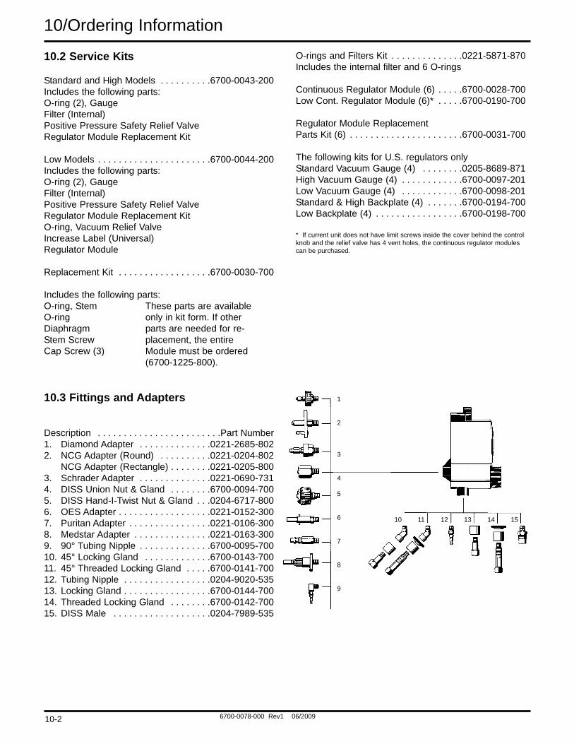
Description Part Number
1. Cover Screw (4) . . . . . . . . . . . . . . .6700-0152-4002. Cover Assembly
Low* . . . . . . . . . . . . . . . . . . . . . . . .6700-0629-850Std/High . . . . . . . . . . . . . . . . . . . . .6700-0628-850
3. Low Vacuum Limiting Screw (2)(Not Shown) (Low Models Only) . .6700-0058-400
* If current unit does not have limit screws inside thecover behind the control knob and the relief valve has 4vent holes, the Std/High part can be purchased.
Description . . . . . . . . . . . . . . . . . . . . . . . .Part Number1. Switch . . . . . . . . . . . . . . . . . . . . . . .6700-0078-5002. Switch Plate
3 Mode . . . . . . . . . . . . . . . . . . . . . .6700-0193-5002 Mode/Low . . . . . . . . . . . . . . . . . .6700-0194-500
3. Screw . . . . . . . . . . . . . . . . . . . . . . .6700-0152-4004. O-ring, Vacuum Relief Valve
(Low Models Only) . . . . . . . . . . . . .6700-0135-5005. Vacuum Relief Valve
& O-ring (Low Models Only) . . . . . .6700-0660-8506. Gauge Assembly (Includes gauge, o-rings and lens)
North American Standard, 0-200 mmHg . . . . . . . . . . . . . . . . . .6700-0050-206North American Low, 0-160 mmHg 6700-0050-207North American High, 0-760 mmHg 6700-0050-208International Low . . . . . . . . . . . . . .6700-0050-209International High . . . . . . . . . . . . . .6700-0050-210International Standard . . . . . . . . . . .6700-0050-211
7. Lens . . . . . . . . . . . . . . . . . . . . . . . .6700-0087-5008. O-ring (2), Gauge . . . . . . . . . . . . . .6700-0130-500
10.1 Illustrated Parts
9. Regulator ModuleStandard/High Models . . . . . . . . . .6700-1225-800Low * . . . . . . . . . . . . . . . . . . . . . . . .6700-0428-800
10. Positive Pressure Safety Relief Valve . . . . . . . . . . . . . . . . . . . . . . . .6700-0115-800
11. Filter (Internal) . . . . . . . . . . . . . . . .0206-5159-30012. Base
North American Standard & High (2 & 3 Mode) . . . . . . . . . . . . . . . . . .6700-0018-203North American Low . . . . . . . . . . . .6700-0029-203International Low . . . . . . . . . . . . . .6700-0029-200International Standard & High . . . .6700-0018-200
13. O-ring, Stem . . . . . . . . . . . . . . . . . .0210-0527-30014. O-ring, Regulator Module . . . . . . . .6700-0136-500
* If current unit does not have limit screws inside thecover behind the control knob and the relief valve has 4vent holes, the Std/High part can be purchased.
1
10
1413
12
111
2
3
4
8
5
9
6
7
3
2
10-1
6700-0078-000 Rev1 06/2009
10.2 Service Kits
Standard and High Models . . . . . . . . . .6700-0043-200Includes the following parts:O-ring (2), GaugeFilter (Internal)Positive Pressure Safety Relief ValveRegulator Module Replacement Kit
Low Models . . . . . . . . . . . . . . . . . . . . . .6700-0044-200Includes the following parts:O-ring (2), GaugeFilter (Internal)Positive Pressure Safety Relief ValveRegulator Module Replacement KitO-ring, Vacuum Relief ValveIncrease Label (Universal)Regulator Module
Replacement Kit . . . . . . . . . . . . . . . . . .6700-0030-700
Includes the following parts:O-ring, Stem These parts are available O-ring only in kit form. If other Diaphragm parts are needed for re-Stem Screw placement, the entire Cap Screw (3) Module must be ordered
(6700-1225-800).
O-rings and Filters Kit . . . . . . . . . . . . . .0221-5871-870Includes the internal filter and 6 O-rings
Continuous Regulator Module (6) . . . . .6700-0028-700Low Cont. Regulator Module (6)* . . . . .6700-0190-700
Regulator Module Replacement Parts Kit (6) . . . . . . . . . . . . . . . . . . . . . .6700-0031-700
The following kits for U.S. regulators onlyStandard Vacuum Gauge (4) . . . . . . . .0205-8689-871High Vacuum Gauge (4) . . . . . . . . . . . .6700-0097-201Low Vacuum Gauge (4) . . . . . . . . . . . .6700-0098-201Standard & High Backplate (4) . . . . . . .6700-0194-700Low Backplate (4) . . . . . . . . . . . . . . . . .6700-0198-700
* If current unit does not have limit screws inside the cover behind the controlknob and the relief valve has 4 vent holes, the continuous regulator modulescan be purchased.
10/Ordering Information
10.3 Fittings and Adapters
Description . . . . . . . . . . . . . . . . . . . . . . . .Part Number1. Diamond Adapter . . . . . . . . . . . . . .0221-2685-8022. NCG Adapter (Round) . . . . . . . . . .0221-0204-802
NCG Adapter (Rectangle) . . . . . . . .0221-0205-8003. Schrader Adapter . . . . . . . . . . . . . .0221-0690-7314. DISS Union Nut & Gland . . . . . . . .6700-0094-7005. DISS Hand-I-Twist Nut & Gland . . .0204-6717-8006. OES Adapter . . . . . . . . . . . . . . . . . .0221-0152-3007. Puritan Adapter . . . . . . . . . . . . . . . .0221-0106-3008. Medstar Adapter . . . . . . . . . . . . . . .0221-0163-3009. 90° Tubing Nipple . . . . . . . . . . . . . .6700-0095-70010. 45° Locking Gland . . . . . . . . . . . . .6700-0143-70011. 45° Threaded Locking Gland . . . . .6700-0141-70012. Tubing Nipple . . . . . . . . . . . . . . . . .0204-9020-53513. Locking Gland . . . . . . . . . . . . . . . . .6700-0144-70014. Threaded Locking Gland . . . . . . . .6700-0142-70015. DISS Male . . . . . . . . . . . . . . . . . . .0204-7989-535
1
2
3
4
5
6
7
8
9
10 11 12 13 14 15
10-2
6700-0078-000 Rev1 06/2009
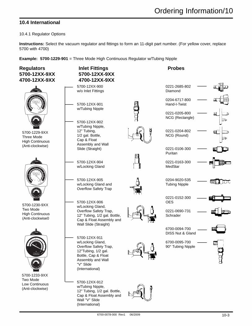
Ordering Information/1010.4 International
10.4.1 Regulator Options
Instructions: Select the vacuum regulator and fittings to form an 11-digit part number. (For yellow cover, replace5700 with 4700)
Example: 5700-1229-901 = Three Mode High Continuous Regulator w/Tubing Nipple
5700-12XX-900w/o Inlet Fittings
5700-12XX-901w/Tubing Nipple
5700-12XX-902w/Tubing Nipple,12" Tubing, 1/2 gal. Bottle,Cap & FloatAssembly and WallSlide (Straight)
5700-12XX-904w/Locking Gland
5700-12XX-905w/Locking Gland andOverflow Safety Trap
5700-12XX-906w/Locking Gland,Overflow Safety Trap,12" Tubing, 1/2 gal. Bottle,Cap & Float Assembly andWall Slide (Straight)
5700-12XX-911w/Locking Gland, Overflow Safety Trap,12"Tubing, 1/2 gal.Bottle, Cap & FloatAssembly and Wall "V" Slide (International)
5700-12XX-912w/Tubing Nipple,12" Tubing, 1/2 gal. Bottle,Cap & Float Assembly andWall "V" Slide (International)
0221-2685-802Diamond
0204-6717-800Hand-I-Twist
0221-0205-800NCG (Rectangle)
0221-0204-802NCG (Round)
0221-0106-300Puritan
0221-0163-300MedStar
0204-9020-535Tubing Nipple
0221-0152-300OES
0221-0690-731Schrader
6700-0094-700DISS Nut & Gland
6700-0095-70090° Tubing Nipple
Regulators Inlet Fittings Probes5700-12XX-9XX 5700-12XX-9XX4700-12XX-9XX 4700-12XX-9XX
High FlowHigh Vacuum
10
20
30
4050
60
70
80
90
100
100
200
300400
500
600
700
- kPa
-mm Hg
High FlowHigh Vacuum
10
20
30
4050
60
70
80
90
100
100
200
300400
500
600
700
- kPa
-mm Hg
- kPa
-mm
Hg
2
4
68
101214
1618
140
20
40
60
80100
120
20
High FlowLow Vacuum
5700-1229-9XXThree ModeHigh Continuous(Anti-clockwise)
5700-1233-9XXTwo ModeLow Continuous(Anti-clockwise)
5700-1230-9XXTwo ModeHigh Continuous(Anti-clockwise0
10-3
6700-0078-000 Rev1 06/2009
10/Ordering Information
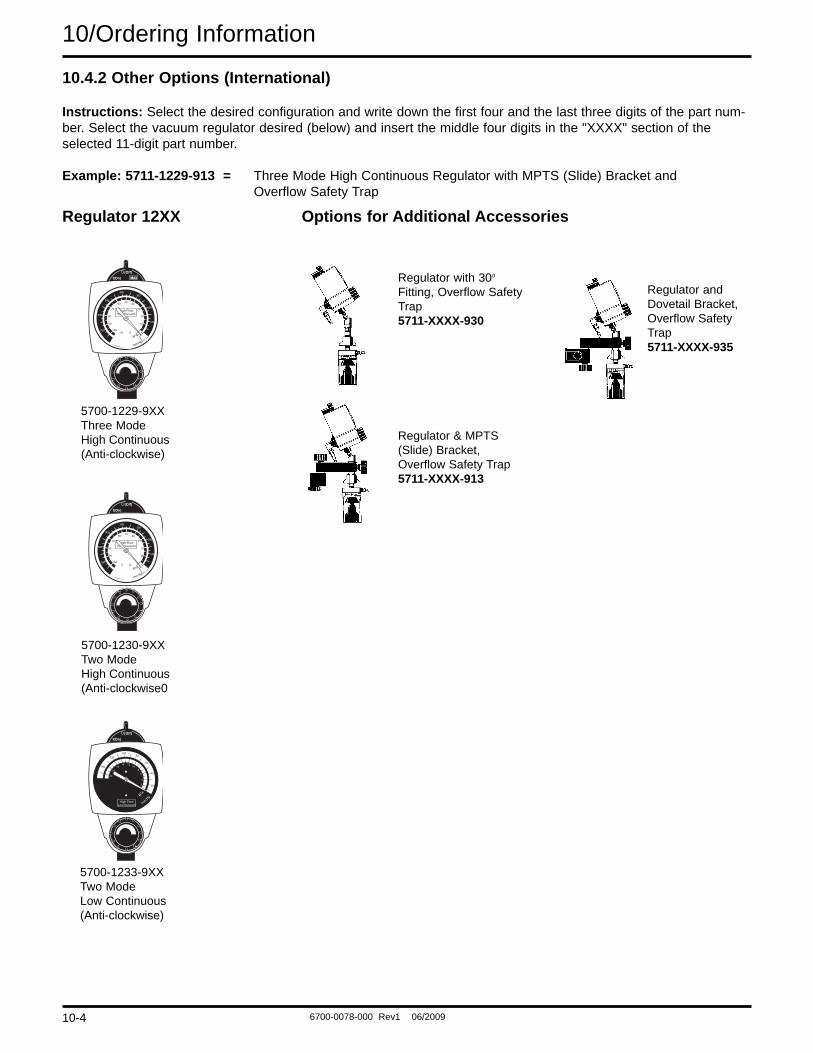
10.4.2 Other Options (International)
Instructions: Select the desired configuration and write down the first four and the last three digits of the part num-ber. Select the vacuum regulator desired (below) and insert the middle four digits in the "XXXX" section of theselected 11-digit part number.
Example: 5711-1229-913 = Three Mode High Continuous Regulator with MPTS (Slide) Bracket and Overflow Safety Trap
High FlowHigh Vacuum
10
20
30
4050
60
70
80
90
100
100
200
300400
500
600
700
- kPa
-mm Hg
High FlowHigh Vacuum
10
20
30
4050
60
70
80
90
100
100
200
300400
500
600
700
- kPa
-mm Hg
- kPa
-mm
Hg
2
4
68
101214
1618
140
20
40
60
80100
120
20
High FlowLow Vacuum
5700-1229-9XXThree ModeHigh Continuous(Anti-clockwise)
5700-1233-9XXTwo ModeLow Continuous(Anti-clockwise)
5700-1230-9XXTwo ModeHigh Continuous(Anti-clockwise0
Regulator 12XX Options for Additional Accessories
Regulator with 30o
Fitting, Overflow SafetyTrap5711-XXXX-930
Regulator & MPTS(Slide) Bracket,Overflow Safety Trap5711-XXXX-913
Regulator andDovetail Bracket,Overflow SafetyTrap5711-XXXX-935
10-4
6700-0078-000 Rev1 06/2009
AppendixInstallation procedure for Adapters/Probesand Fittings.
All adapters/probes and fittings should be sealed andinstalled properly to prevent leaks and to support theequipment when mounted. Both vacuum regulator portsare 1/8-27 NPTF tapered pipe threads. It is important tonote that adapters/probes and fittings seal on the threadand may have threads exposed after they have beentightened properly.
Prior to installing the adapter/probe or fitting, seal thethread with Teflon® (PTFE) tape or one of the followinglubricants:
Dow® 111 (Ohio Medical P/N 6700-0074-200)
Ball Vac Kote (37951M) (Ohio Medical P/N 0220-0091-300)
CAUTION Do not use any Loctite products to sealthe threads (or products which containMethacrylate Ester as an active ingredi-ent).
The torque range for installing adapters/probes and fit-tings is 4.0 ft-lb (5.4 N-m) minimum to 10.0 ft-lb (13.6 N-m) maximum.
Adapters/probes and fittings which are not keyed forspecific orientation, should be torqued to approximately6.0 ft-lb (8.1 N-m).
Adapters/probes and fittings that are keyed to specificorientation, must be torqued initially to 4.0 ft-lbs.Additional torque is applied only until orientation is cor-rect.
®Teflon is a registered trademark of the DuPoint Company.
A-1
6700-0078-000 Rev1 06/2009
Ohio Medical CorporationAuthorized Representative(OxygenCare Ltd.)Corrig RoadSandyford Industrial Est.Dublin 8IrelandPhone +35 31 295 3421
North America
United States
Customer Service and Distribution CenterTechnical SupportSales and ServiceEquipment Service Center
Ohio Medical Corporation1111 Lakeside DriveGurnee, Il, 60031-4099 USAToll free: 866-549-6446Phone: +1 847-855-0800Fax: +1 847-855-6218
www.ohiomedical.com