Continuous Gas Analyzers, in-situ - RAECO · Continuous Gas Analyzers, in-situ LDS 6 General...
27
Continuous Gas Analyzers, in-situ LDS 6 General information 3/3 Siemens PA 01 · 2012 3 ■ Overview LDS 6 is a diode laser gas analyzer with a measuring principle based on the specific light absorption of different gas compo- nents. LDS 6 is suitable for fast and non-contact measurement of gas concentrations or temperatures in process or flue gases. One or two signals from up to three measuring points are pro- cessed simultaneously by the central analyzer unit. The in-situ cross-duct sensors at each measuring point can be separated up to 700 m from the central unit by using fiber-optic cables. The sensors are designed for operation under harsh environmental conditions and contain a minimum of electrical components. LDS 6, typical installation with transmitted-light sensors ■ Benefits The in-situ gas analyzer LDS 6 is characterized by a high avail- ability and unique analytical selectivity, and is optimally suitable for numerous applications. LDS 6 enables the measurement of one or two gas components or - if desired - the gas temperature directly in the process: • With high dust load • In hot, humid, corrosive, explosive, or toxic gases • In applications showing strong varying gas compositions • Under harsh environmental conditions at the measuring point • Highly selective, i.e. mostly without cross-sensitivities LDS 6 properties: • Little installation effort • Minimum maintenance requirements • Extremely rugged design • High long-term stability through built-in, maintenance-free reference gas cell, field calibration is unnecessary • Real-time measurements Moreover, the instrument provides warning and failure messages upon: • Need for maintenance - Erroneous reference function - Bad signal quality • Violation of a lower or upper alarm level for the measured variable • Transmitted amount of light violating an upper or lower limit ■ Application Applications • Process optimization • Continuous emission monitoring for all kinds of fuels (oil, gas, coal, and others) • Process measurements in power utilities and any kind of incinerator • Process control • Explosion protection • Measurements in corrosive and toxic gases • Quality control • Environmental protection • Plant and operator safety Sectors • Power plants • Steel works • Cement industry • Chemical and petrochemical plants • Automotive industry • Waste incinerators • Glass and ceramics production • Research and development Special applications In addition to the standard applications, special applications are available upon request. © Siemens AG 2011
Transcript of Continuous Gas Analyzers, in-situ - RAECO · Continuous Gas Analyzers, in-situ LDS 6 General...

Continuous Gas Analyzers, in-situLDS 6
General information
3/3Siemens PA 01 · 2012
3
■ Overview
LDS 6 is a diode laser gas analyzer with a measuring principle based on the specific light absorption of different gas compo-nents. LDS 6 is suitable for fast and non-contact measurement of gas concentrations or temperatures in process or flue gases. One or two signals from up to three measuring points are pro-cessed simultaneously by the central analyzer unit. The in-situ cross-duct sensors at each measuring point can be separated up to 700 m from the central unit by using fiber-optic cables. The sensors are designed for operation under harsh environmental conditions and contain a minimum of electrical components.
LDS 6, typical installation with transmitted-light sensors
■ Benefits
The in-situ gas analyzer LDS 6 is characterized by a high avail-ability and unique analytical selectivity, and is optimally suitable for numerous applications. LDS 6 enables the measurement of one or two gas components or - if desired - the gas temperature directly in the process:• With high dust load• In hot, humid, corrosive, explosive, or toxic gases • In applications showing strong varying gas compositions • Under harsh environmental conditions at the measuring point• Highly selective, i.e. mostly without cross-sensitivities
LDS 6 properties:• Little installation effort• Minimum maintenance requirements• Extremely rugged design• High long-term stability through built-in, maintenance-free
reference gas cell, field calibration is unnecessary• Real-time measurements
Moreover, the instrument provides warning and failure messages upon:• Need for maintenance
- Erroneous reference function- Bad signal quality
• Violation of a lower or upper alarm level for the measured variable
• Transmitted amount of light violating an upper or lower limit
■ Application
Applications• Process optimization• Continuous emission monitoring for all kinds of fuels
(oil, gas, coal, and others) • Process measurements in power utilities and any kind of
incinerator• Process control• Explosion protection• Measurements in corrosive and toxic gases• Quality control• Environmental protection• Plant and operator safety
Sectors• Power plants• Steel works• Cement industry• Chemical and petrochemical plants• Automotive industry• Waste incinerators• Glass and ceramics production• Research and development
Special applications
In addition to the standard applications, special applications are available upon request.
PA01_2012_EN.book Seite 3 Freitag, 30. September 2011 11:09 11
© Siemens AG 2011

Continuous Gas Analyzers, in-situLDS 6
General information
3/4 Siemens PA 01 · 2012
3
■ Design
The gas analyzer LDS 6 consists of a central unit and up to three in-situ sensors. The connection between the central unit and the sensors is established by a so-called hybrid cable, which contains optical fibers and copper wires. An additional cable connects the transmitter and receiver parts of the cross-duct sensor.
Central unit
The central unit is housed in a 19" rack unit enclosure with 4 holders for mounting• in a hinged frame• in racks with or without telescopic rails
Display and control panel• Large LCD field for simultaneous display of measurement
result and device status• Contrast of the LCD field is adjustable via the menu• LED background illumination of the display with energy-
saving function• Easy-to-clean membrane touch pad with softkeys• Menu-driven operation for parameterization and diagnostics• Operation support in plain text
Input and outputs• One to three measurement channels with hybrid connections
for the sensors at the measuring points• 2 analog inputs per channel for process gas temperature and
pressure• 2 analog outputs per channel for gas concentration(s) or for
gas temperature and concentration For selected versions, the transmission can be read out as an alternative.
• 6 freely configurable binary inputs per channel for signaling faults or maintenance requests from external temperature or pressure transducers or sensor purging failure.
• 6 freely configurable binary outputs per channel (signaling of fault, maintenance requirements, function control, transmis-sion limit alarm, concentration limit alarm, store analog output)
Communication
Network connection: Ethernet (T-Base-10) for remote diagnos-tics and maintenance.
LDS 6 central unit, membrane keyboard and graphic display
Status line to indicate the device status
LED-backlit graphicdisplay and membrane tactile-touch keyboard
Two code levelsaccording to NAMUR
MEAS key to return direct tomeasurement mode
Menu-driven operator controlwith five softkeys
ESC keyto cancel entries
INFO keyfor help in plain text
CLEAR key to delete the digits entered
Numeric keypadfor entering digits
Numeric displayof concentrations
ENTER key to adopt the numbers
PA01_2012_EN.book Seite 4 Freitag, 30. September 2011 11:09 11
© Siemens AG 2011
Continuous Gas Analyzers, in-situLDS 6
General information
3/5Siemens PA 01 · 2012
3
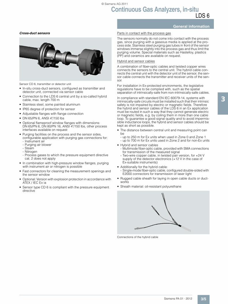
Cross-duct sensors
Sensor CD 6, transmitter or detector unit
• In-situ cross-duct sensors, configured as transmitter and detector unit, connected via sensor cable
• Connection to the LDS 6 central unit by a so-called hybrid cable, max. length 700 m
• Stainless steel, some painted aluminum• IP65 degree of protection for sensor• Adjustable flanges with flange connection• DN 65/PN 6, ANSI 4"/150 lbs • Optional flameproof window flanges with dimensions:
DN 65/PN 6, DN 80/PN 16, ANSI 4"/150 lbs, other process interfaces available on request
• Purging facilities on the process and the sensor sides, configurable application with purging gas connections for: - Instrument air- Purging air blower- Steam- Nitrogen- Process gases to which the pressure equipment directive
cat. 2 does not apply • In combination with high-pressure window flanges, purging
with instrument air or nitrogen is possible• Fast connectors for cleaning the measurement openings and
the sensor window• Optional: Version with explosion protection in accordance with
ATEX / IEC Ex ia• Sensor type CD 6 is compliant with the pressure equipment
directive
Parts in contact with the process gas
The sensors normally do not come into contact with the process gas, since purging with a gaseous media is applied at the pro-cess side. Stainless steel purging gas tubes in front of the sensor windows immerse slightly into the process gas and thus limit the purging volume. Special materials such as Hastelloy, plastics (PP) and ceramics are available on request.
Hybrid and sensor cables
A combination of fiber-optic cables and twisted copper wires connects the sensors to the central unit. The hybrid cable con-nects the central unit with the detector unit of the sensor, the sen-sor cable connects the transmitter and receiver units of the sen-sor.
For installation in Ex-protected environments, the legislative regulations have to be complied with, such as the spatial separation of intrinsically-safe from non-intrinsically-safe cables.
In compliance with standard EN IEC 60079-14, systems with intrinsically-safe circuits must be installed such that their intrinsic safety is not impaired by electric or magnetic fields. Therefore the hybrid and sensor cables of the LDS 6 in an Ex application must be routed in such a way that they cannot generate electric or magnetic fields, e.g. by coiling them in more than one cable loop. To guarantee a good signal quality and to avoid impermis-sible inductance loops, the hybrid and sensor cables should be kept as short as possible.• The distance between central unit and measuring point can
be - up to 250 m for Ex units when used in Zone 0 and Zone 1- up to 700 m for Ex units used in Zone 2 and for non-Ex units
• Hybrid and sensor cables - Multimode fiber-optic cable, provided with SMA connections
for transmission of the measured signal- Two-wire copper cable, in twisted pair version, for +24 V
supply of the detector electronics (+12 V in the case of Ex-suitable instruments)
• Additionally for the hybrid cable: - Single-mode fiber-optic cable, configured double-sided with
E2000 connectors for transmission of laser light• Rugged cable sheath for laying in open cable ducts or duct-
works• Sheath material: oil-resistant polyurethane
Connections of the hybrid cable
PA01_2012_EN.book Seite 5 Freitag, 30. September 2011 11:09 11
© Siemens AG 2011
Continuous Gas Analyzers, in-situLDS 6
General information
3/6 Siemens PA 01 · 2012
3
■ Function
Operating principle
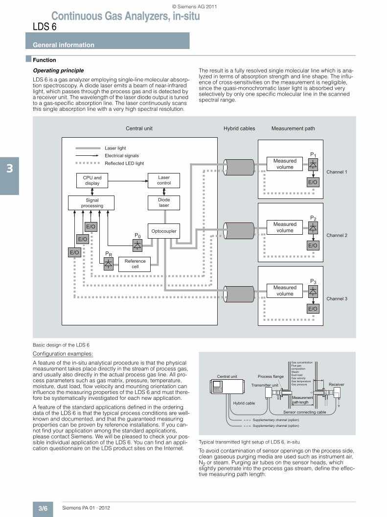
LDS 6 is a gas analyzer employing single-line molecular absorp-tion spectroscopy. A diode laser emits a beam of near-infrared light, which passes through the process gas and is detected by a receiver unit. The wavelength of the laser diode output is tuned to a gas-specific absorption line. The laser continuously scans this single absorption line with a very high spectral resolution.
The result is a fully resolved single molecular line which is ana-lyzed in terms of absorption strength and line shape. The influ-ence of cross-sensitivities on the measurement is negligible, since the quasi-monochromatic laser light is absorbed very selectively by only one specific molecular line in the scanned spectral range.
Basic design of the LDS 6
Configuration examples:
A feature of the in-situ analytical procedure is that the physical measurement takes place directly in the stream of process gas, and usually also directly in the actual process gas line. All pro-cess parameters such as gas matrix, pressure, temperature, moisture, dust load, flow velocity and mounting orientation can influence the measuring properties of the LDS 6 and must there-fore be systematically investigated for each new application.
A feature of the standard applications defined in the ordering data of the LDS 6 is that the typical process conditions are well-known and documented, and that the guaranteed measuring properties can be proven by reference installations. If you can-not find your application among the standard applications, please contact Siemens. We will be pleased to check your pos-sible individual application of the LDS 6. You can find an appli-cation questionnaire on the LDS product sites on the Internet.
Typical transmitted light setup of LDS 6, in-situ
To avoid contamination of sensor openings on the process side, clean gaseous purging media are used such as instrument air, N2 or steam. Purging air tubes on the sensor heads, which slightly penetrate into the process gas stream, define the effec-tive measuring path length.
P1
P0
PR
P2
P3
Measuredvolume
E/O
Channel 1Lasercontrol
Diodelaser
Optocoupler
Referencecell
CPU anddisplay
Signalprocessing
Laser lightElectrical signals
Reflected LED light
Central unit Hybrid cables Measurement path
E/O
E/O
E/O
Measuredvolume
Measuredvolume
Channel 2
Channel 3
E/O
E/O
Central unit
Hybrid cable
Supplementary channel (option)
Supplementary channel (option)
Transmitter unit Receiver
Process flange
Sensor connecting cable
Measurement path length
Gas concentrationFlue gas compositionSteamDust loadGas velocityGas temperatureGas pressure
PA01_2012_EN.book Seite 6 Freitag, 30. September 2011 11:09 11
© Siemens AG 2011
Continuous Gas Analyzers, in-situLDS 6
General information
3/7Siemens PA 01 · 2012
3
The LDS 6 can measure in both the transverse and longitudinal directions of the process gas flow. In certain cases, the process conditions make it necessary to condition the sample gas stream in a bypass line with respect to process temperature, pressure and/or optical path length. Further treatment of the process gas, such as drying or dust precipitation, is usually unnecessary.
Typical transmitted light setup of LDS 6, in bypass
A flow cell is available by special application for the LDS 6 which has been specially optimized for use with the LDS 6 and its transmitted-light sensors with respect to handling and measur-ing performance. It is designed to reduce surface effects, and is therefore also highly suitable for polar gases like ammonia. This flow cell is available in heated and non-heated versions. Wheel mounted and wall mounted versions are available.
Measuring configuration of LDS 6 with heated flow cell
General information
LDS 6 is connected to the measuring points by fiber optics. The laser light is guided by a single-mode fiber from the central unit to the transmitter unit of the in-situ sensor. The sensor consists of a transmitter and a receiver; the distance between them defines the measurement path. In the receiver box, the light is focused onto a suitable detector. The detector signal is then converted into an optical signal and transmitted via a second optical fiber to the central unit, where the concentration of the gas compo-nent is determined from the detected absorption signal.
LDS 6 usually measures a single gas component by means of the absorption capacity of a single fully resolved molecular ab-sorption line. The absorption results from conversion of the radi-ation energy of the laser light into the internal energy of the mol-ecule. In the working range of the LDS 6, both rotation-vibration transitions and electronic transitions - such as with O2 - can be triggered.
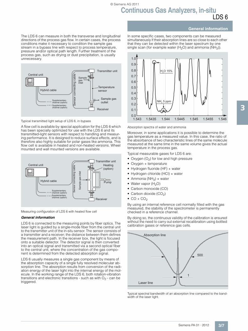
In some specific cases, two components can be measured simultaneously if their absorption lines are so close to each other that they can be detected within the laser spectrum by one single scan (for example water (H2O) and ammonia (NH3)).
Absorption spectra of water and ammonia
Moreover, in some applications it is possible to determine the gas temperature as a measured value. In this case, the ratio of the absorbance of two characteristic lines of the same molecule measured at the same time in the same volume gives the actual temperature in the process gas.
Typical measurable gases for LDS 6 are:• Oxygen (O2) for low and high pressure• Oxygen + temperature• Hydrogen fluoride (HF) + water• Hydrogen chloride (HCl) + water• Ammonia (NH3) + water• Water vapor (H2O)• Carbon monoxide (CO)• Carbon dioxide (CO2)• CO + CO2
By using an internal reference cell normally filled with the gas measured, the stability of the spectrometer is permanently checked in a reference channel.
By doing so, the continuous validity of the calibration is ensured without the need to carry out external recalibration using bottled calibration gases or reference gas cells.
Typical spectral bandwidth of an absorption line compared to the band-width of the laser light.
Transmitter unitCentral unit
Receiver
Sample gas outlet
Sample gas inlet
Temperature sensorHybrid cable
Supplementary channel (option)Supplementary channel (option)
Sen
sor c
onne
ctin
g ca
ble
Transmitter unitCentral unit
Receiver
Sam
ple
gas
inle
t
PumpHybrid cable
Supplementary channel (option)Supplementary channel (option)
Sen
sor c
onne
ctin
g ca
ble Heating
(option)
PA01_2012_EN.book Seite 7 Freitag, 30. September 2011 11:09 11
© Siemens AG 2011

Continuous Gas Analyzers, in-situLDS 6
General information
3/8 Siemens PA 01 · 2012
3
Influences on the measurement
Dust load
As long as the laser beam is able to generate a suitable detector signal, the dust load of the process gases does not influence the analytical result. By applying a dynamic background correction, measurements can be carried out without any negative impact. Under good conditions, particle densities up to 100 g/Nm3 can be handled by the LDS 6. Varying dust loads are compensated by scanning the laser over the gas absorption line and the cur-rent background. At a scan position next to the absorption line, the instrument can "see" only absorption caused by the dust load where at the line center the signal is composed of the molecular absorption and the continuous, unspecific background absorp-tion. With the wavelength modulation technique, the actual mea-sured transmission is always compared with the baseline. After signal processing, phase-sensitive application delivers a signal only from the molecular line free of background.The influence of a high dust load is complex and depends on the path length and particle size. The optical damping increases at longer path lengths. Smaller particles also have a large influence on the optical damping. With a combination of high dust load, long path length and small particle size, the technical support at Siemens should be consulted.
Temperature
The temperature influence on the absorption line strength is compensated by a correction factor determined during calibra-tion. A temperature signal can be fed into the instrument from an external temperature sensor. This signal is then used to correct the influence of the temperature on the observed line strength. If the temperature of the sample gas remains constant, it is alter-natively possible to carry out a static correction using a preset value.At high process gas temperatures, generally from approximately 1 000 °C, there may be noticeable broadband IR radiation of gas and dust, or flames may occasionally occur in the measurement path. An additional optical bandpass filter can be set upstream of the detector to protect it and prevent saturation by the strong background radiation.
Pressure
The gas pressure can affect the line shape of the molecular ab-sorption line. LDS 6 uses a special algorithm to adapt the line shape. Additionally, an external pressure signal can be fed to the instrument to provide complete compensation for the pressure influence including the density effect.
Cross-interferences
Since LDS 6 derives its signal from a single fully resolved molec-ular absorption line, cross-interferences with other gases are quite unlikely. LDS 6 is therefore able to measure the desired gas components very selectively. In special cases, the composition of the process gas might have an influence on the shape of the absorption line features. This influence is compensated by ana-lyzing the full shape of the detected signal curve applying spe-cific algorithms.
Optical path length
The absorption values analyzed by the LDS 6 are typically small. As a result of Beer-Lambert’s law, the absorption of laser light de-pends on the optical path length within the gas. Therefore, the precision in determining the effective optical path length in the process might limit the overall precision of the measurement.As the sensor openings toward the process normally need to be purged to keep them clean over a long period of time, the thick-ness of the mixing zone between the purging medium and the process gas and its concentration distribution need to be con-sidered. In a typical in-situ installation directly in the line and with some meters of path, the influence of the purging gas on the ef-fective path length can be neglected.Path length and dust load are mutually influencing: the higher the dust load in the process, the shorter the max. possible path length.
Maintenance and fault messages
LDS 6 outputs different warnings via relays:• Need for maintenance (measured value is not influenced)• Operating error (measured value might be influenced)
Note
Individual requirements for the measuring point can make the utilization of special sensor equipment necessary. The possibili-ties for adapting the sensors are:• Different purging media, such as instrument air, ambient air,
nitrogen or steam• Different purging modes on process and sensor sides• Special materials of purging tubes and/or sensor flanges• Cooling or heating of the sensors• Explosion-protected sensor configurations
Essential characteristics• Integrated calibration adjustment with an internal reference
cell• Negligible long-term drifts of zero and span• Dynamic background correction for varying dust loads• Isolated signal outputs, 4 to 20 mA • User-friendly, menu-driven operation• Selectable time constants (response time)• Two user levels with individual access codes for prevention of
unwanted and unauthorized operations• Operation according to NAMUR recommendations• Monitoring of overall optical transmission• Remote preventive maintenance and servicing via
Ethernet/modem• Straightforward replacement of the central unit, since connec-
tions can easily be removed• Sensor and central unit housing free of wear and corrosion• Easy operation with a numerical keypad and menu prompting
PA01_2012_EN.book Seite 8 Freitag, 30. September 2011 11:09 11
© Siemens AG 2011

Continuous Gas Analyzers, in-situLDS 6
General information
3/9Siemens PA 01 · 2012
3
Certified versions for emission monitoring
The LDS 6 is available as certified instrument for emission mon-itoring of NH3, NH3/H2O, H2O, HCl, HCl/H2O. The certificates are issued by TÜV for Germany and MCERTS for the United Kingdom. For conducting regular calibration and linearity checks, test kits for ammonia, water and HCl should be used. These kits can be ordered separately as instrument accessories. For new analyzer orders, the NH3, NH3/H2O and H2O kits named "Version 2" must be ordered. For already installed analyzers, please contact Siemens for spotting the correct kit version, or consult the instrument manual.
Verification of calibration
Assembly with certified, maintenance-free calibration gas cell with connections for laser fiber-optic conductors and detector module of cross-duct sensor. Serves to rapidly verify the factory calibration in the field without compressed gas bottles and flow cell.
Calibration verification kits are available for the following sample gases: O2 (application codes AA, AC, AD), NH3, CO, CO2, CO/CO2. A "Zero gas test kit" is also available (see "Additional units")
Example of an assembly for verification of calibration
PA01_2012_EN.book Seite 9 Freitag, 30. September 2011 11:09 11
© Siemens AG 2011

Continuous Gas Analyzers, in-situLDS 6
19" central unit
3/10 Siemens PA 01 · 2012
3
■ Technical specifications Analytical performance
Measuring range Adjustable
Detection limit (DL):Calculated in accordance with VDI 2449, measured on every sup-plied analyzer during the tempera-ture test (between 5 ... 45 °C) in accordance with VDI 4203.
Depending on sample gas com-ponent: see table for standard applications.For Code ET and FT: in accor-dance with the requirements of 17th and 27th BImSchV
Smallest recommended measuring range (with 1 m path length)
Depending on sample gas com-ponent: see table for standard applications.
The maximum applicable measuring ranges can be found in the table of standard combinations. These can only be applied if the individual process conditions allow it. Please contact the Technical Support from Siemens for checking the applicability.
Accuracy 2 % / 5 %, depending on sample gas component and application letter. At best: detection limit. See table for standard applications.For Code ET and FT: in accor-dance with the requirements of 17th and 27th BImSchV
Linearity Better than 1 %
Repeatability 2 % of the measured value or minimum detection limit (which-ever is largest)For Code ET and FT: in accor-dance with the requirements of 17th and 27th BImSchV
Calibration interval No recalibration required thanks to internal reference cell
General information
Concentration units ppmv, Vol%, mg/Nm3
Display Digital concentration display (5 digits with floating decimal point)
Laser protection class Class 1, safe to the eye
Certificates CE marking, TÜV, MCERTS
Design, enclosure
Degree of protection IP20 according to EN 60529
Dimensions 177 x 440 x 380 mm
Weight Approx. 13 kg
Mounting Horizontal
Electrical characteristics
Power supply 100 ... 240 V, AC 50 ... 60 Hz, automatically adapted by the sys-tem; with a 3-channel central unit, an additional external power sup-ply +24 V DC, 50 VA is included in the scope of delivery
Power consumption 50 W
EMC According to EN 61326 and standard classification of NAMUR NE21
Electrical safety According to EN 61010-1, overvoltage classification II
Fuse specifications 100 ... 240 V: T2.5L250V
Dynamic response
Warm-up time at 20 °C ambient temperature
Approx. 15 min
Response time Less than 3 s, application-depen-dent
Integration time 1 … 100 s, adjustable
Influencing variables
Ambient temperature < 0.5 %/10 K of the measured value
Atmospheric pressure Negligible
Process gas pressure compensation
Recommended
Process gas pressure range See table for standard applica-tions
Power supply changes < 1 %/30 V
Electrical inputs and outputs
Number of measurement channels 1 … 3, optional
Analog output 2 per channel, 4 ... 20 mA, float-ing, ohmic resistance max. 750 Ω
Analog inputs 2 per channel, designed for 4 ... 20 mA, 50 Ω
Binary outputs 6 per channel, with changeover contacts, configurable, 24 V AC/DC/1 A, floating
Binary inputs 6 per channel, designed for 24 V, floating, configurable
Communication interface Ethernet 10BaseT (RJ-45)
Climatic conditions
Temperature range 5 … 45 °C during operation, -40 … +70 °C during storage and transportation
Atmospheric pressure 800 … 1 200 hPa
Humidity < 85 % relative humidity, above dew point (in operation and storage)
PA01_2012_EN.book Seite 10 Freitag, 30. September 2011 11:09 11
© Siemens AG 2011

Continuous Gas Analyzers, in-situLDS 6
19" central unit
3/11Siemens PA 01 · 2012
3
Selection and ordering data Order No.
LDS 6 in-situ gas analyzer19" rack unit for installation in cabinets
C) 7MB6121- 777 0 0 - 0 777
Explosion protectionWithout, not suitable for connection to Ex sensors 0Without, suitable for connection to Ex sensors in accordance with ATEX II 1 G Ex ia IIC T4, ATEX II 1D Ex iaD 20 IP65 T135 °C
1
Measured component Possible with application letter of the respective channel
O2 B, C, P AO2/temp B B
NH3 A, E, F, T CNH3/H2O A, E, F, T D
HCl A, H, T EHCl/H2O A, H, T F
HF A, H A) GHF/H2O A, H A) H
CO C JCO/CO2 D K
CO2 A LH2O A, T M
Application letter of measured component channel 1
Application examples channel 11)
A Emission monitoring, non-certified AB Emission monitoring, combustion
optimizationB
C Safety monitoring with appropriate plant concept
C
D Process control D
E SNCR-DeNOx EF SCR-DeNOx F
H Filter optimization HP Process control (high pressure) P
T Emission monitoring, certified according to 17th BImSchV and MCerts, in combination with measured component variants C, D, E, F, M
T
Application letter of measured component channel 2
Application examples channel 21)
X Channel 2 not used XA Emission monitoring AB Combustion optimization B
C Safety monitoring with appropriate plant con-cept
C
D Process control D
E SNCR-DeNOx EF SCR-DeNOx F
H Filter optimization HP Process control (high pressure) P
T Emission monitoring, certified according to 17th BImSchV and MCerts, in combination with measured component variants C, D, E, F, M
T
A) Subject to export regulations AL: 2B351A, ECCN: EAR99C) Subject to export regulations AL: N, ECCN: EAR991) The examples shown represent possible applications where appropriately configured LDS 6 solutions can be used. The user is responsible for the prevailing
conditions (plant concept (possibly redundant), application of appropriate components required in addition, compliance with possible directives, etc.).
PA01_2012_EN.book Seite 11 Freitag, 30. September 2011 11:09 11
© Siemens AG 2011

Continuous Gas Analyzers, in-situLDS 6
19" central unit
3/12 Siemens PA 01 · 2012
3
B) Subject to export regulations AL: N, ECCN: 3A991XD) Subject to export regulations AL: 9I999, ECCN: NE) Subject to export regulations AL: 9I999, ECCN: 3A991X
The examples shown represent possible applications where appropriately configured LDS 6 solutions can be used. The user is re-sponsible for the prevailing conditions (plant concept (possibly redundant), application of appropriate components required in ad-dition, compliance with possible directives, etc.).
Application letter of measured component channel 3
Application examples channel 31)
External 24 V DC power supply included in scope of delivery
X Channel 3 not used XA Emission monitoring AB Combustion optimization B
C Safety monitoring with appropriate plant concept
C
D Process control D
E SNCR-DeNOx EF SCR-DeNOx F
H Filter optimization HP Process control (high pressure) P
T Emission monitoring, certified according to 17th BImSchV and MCerts, in combination with measured component variants C, D, E, F, M
T
Language (supplied documentation, software)German 0English 1French 2Spanish 3Italian 4
Selection and ordering data Order No.
LDS 6 in-situ gas analyzer19" rack unit for installation in cabinets
C) 7MB6121- 777 0 0 - 0 777
Selection and ordering dataAdditional versions Order codeAdd "-Z" to Order No. and specify order codeTelescopic rails (2 units) A31Set of Torx tools A32TAG labels (customized inscription) Y30Additional units Order No.External power supply for hybrid cable length > 500 m A5E00854188Calibration verification kit for NH3 (version 2) E) A5E01075594TÜV/MCERT calibration verification kit NH3 (version 2), 2 cells B) A5E00823339013TÜV/MCERT calibration verification kit NH3/H2O (version 2), 3 cells B) A5E00823339014TÜV/MCERT calibration verification kit H2O (version 2), 2 cells B) A5E00823339015Calibration verification kit for NH3 (version 1) B) A5E00534675TÜV/MCERT calibration verification kit NH3 (version 1), 2 cells E) A5E00823339003TÜV/MCERT calibration verification kit NH3/H2O (version 1), 3 cells D) A5E00823339004TÜV/MCERT calibration verification kit H2O (version 1), 2 cells D) A5E00823339005TÜV/MCERT calibration verification kit HCl, 2 cells B) A5E00823339008TÜV/MCERT calibration verification kit HCl/H2O, 3 cells B) A5E00823339009Calibration verification kit for O2 (version 2) B) A5E01143755001Calibration verification kit for CO (version 2) B) A5E01143755003Calibration verification kit for CO2 (version 2) B) A5E01143755004Calibration verification kit for CO/CO2 (version 2) A5E01143755006Zero gas verification kit for all gases except O2 A5E00823386009
PA01_2012_EN.book Seite 12 Freitag, 30. September 2011 11:09 11
© Siemens AG 2011
Continuous Gas Analyzers, in-situLDS 6
19" central unit
3/13Siemens PA 01 · 2012
3
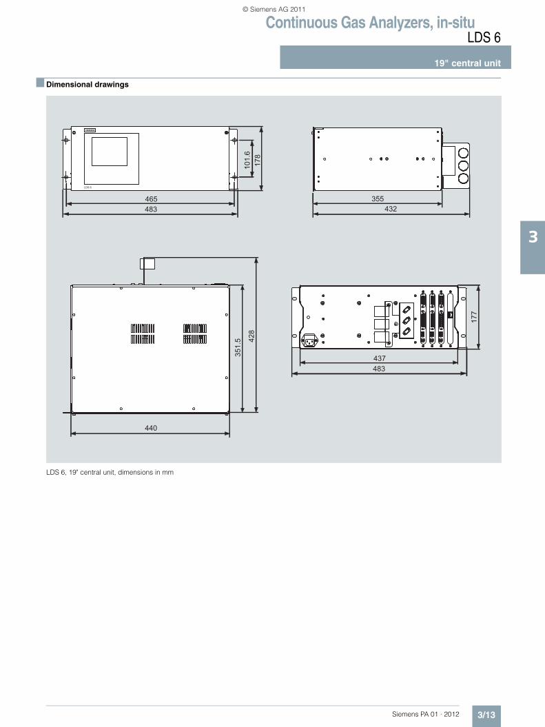
■ Dimensional drawings
LDS 6, 19" central unit, dimensions in mm
s
LDS 6
428
440
465483
178
355432
483437
177
351.
510
1.6
PA01_2012_EN.book Seite 13 Freitag, 30. September 2011 11:09 11
© Siemens AG 2011

Continuous Gas Analyzers, in-situLDS 6
19" central unit
3/14 Siemens PA 01 · 2012
3
■ Schematics
Pin assignments
LDS 6, 19" central unit, pin assignments
Ω
Ω)
PA01_2012_EN.book Seite 14 Freitag, 30. September 2011 11:09 11
© Siemens AG 2011

Continuous Gas Analyzers, in-situLDS 6
19" central unit
3/15Siemens PA 01 · 2012
3
Optical and electrical connections
LDS 6, three-channel 19" central unit, optical and electrical connections
Power supply and fuses
25-pin connector:Binary inputs andrelay outputs
15-pin connector:Binary inputs andanalog inputs/outputs
Hybrid cable support
E2000single modeopto-connector
SMAmultimodeopto-connector
EthernetconverterRJ-45
24 V DC sensor supply
PA01_2012_EN.book Seite 15 Freitag, 30. September 2011 11:09 11
© Siemens AG 2011

Continuous Gas Analyzers, in-situLDS 6
19" central unit
3/16 Siemens PA 01 · 2012
3
■ More information
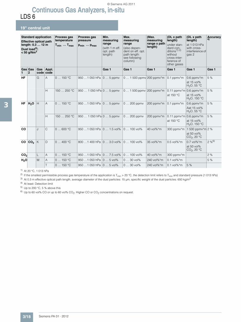
The following table lists the measuring conditions for standard applications. The listed values for the measuring range and de-tection limit (DL) are only approximate values. The exact values at the respective measuring point depend on the totality of all in-fluencing variables and can be determined by Siemens for the specific case.
Please note that the values for the detection limit and the maxi-mum measuring range refer to an optical path of 1 m. Longer path lengths will improve the detection limit, but not linearly. Due to limiting effects such as dust load. The maximum applicable measuring ranges can only be used if permitted by the process conditions such as dust load.
Standard applicationEffective optical path length: 0.3 … 12 mDust load3): < 50 g/Nm3
Process gas temperatureTmin … Tmax
Process gas pressurepmin … pmax
Min. measuring range(with 1 m eff. opt. path length)
Max. measuring range (also depen-dent on eff. opt. path length: see following column)
(Max. measuring range x path length)
(DL x path length)under stan-dard con-ditions1) 2)
without cross-inter-ference of other gases
(DL x path length)at 1 013 hPa with cross-interference of gas 2
Accuracy4)
Gas 1
Gas 2
Gas code
Appl. code
Gas 1 Gas 1 Gas 1 Gas 1 Gas 1 Gas 1
O2 A B 600 … 1 200 °C 950 …1 050 hPa 0 … 15 vol% 0 … 100 vol% 240 vol%*m 0.3 vol%*mat 600 °C
5 %
C 0 … 600 °C 950 …1 050 hPa 0 … 5 vol% 0 … 100 vol% 75 vol%*m 0.1 vol%*m 2 %5)
P 0 … 200 °C 950 …5 000 hPa 0 … 5 vol% 0 … 100 vol% 75 vol%*m 0.1 vol%*m 2 %
O2 Temp B B 600 … 1 200 °C 950 …1 050 hPa 0 … 35 vol% 0 … 100 vol% 240 vol%*m 0.7 vol%*mat 600 °C
5 %
NH3 C A 0 … 150 °C 950 …1 050 hPa 0 … 25 ppmv 0 … 500 ppmv 2 500 ppmv*m 0.5 ppmv*m 0.9 ppmv*m at 15 vol% H2O, 55 °C
2 %
T 0 … 150 °C 950 …1 050 hPa 0 … 25 ppmv 0 … 500 ppmv 2 500 ppmv*m 0.5 ppmv*m 0.9 ppmv*m at 15 vol% H2O, 55 °C
2 %
E 250 … 350 °C 950 …1 050 hPa 0 … 45 ppmv 0 … 500 ppmv 2 500 ppmv*m 0.9 ppmv*mat 250 °C
1.4 ppmv*mat 15 Vol% H2O, 250 °C
2 %
F 300 … 400 °C 950 …1 050 hPa 0 … 50 ppmv 0 … 500 ppmv 2 500 ppmv*m 1 ppmv*mat 300 °C
1.5 ppmv*mat 15 Vol% H2O, 300 °C
2 %
NH3 H2O D A 0 … 150 °C 950 …1 050 hPa 0 … 25 ppmv 0 … 100 ppmv 1 200 ppmv*m 0.5 ppmv*m 0.9 ppmv*m at 15 vol% H2O, 55 °C
2 %
T 0 … 150 °C 950 …1 050 hPa 0 … 25 ppmv 0 … 100 ppmv 1 200 ppmv*m 0.5 ppmv*m 0.9 ppmv*m at 15 vol% H2O, 55 °C
2 %
E 250 … 350 °C 950 …1 050 hPa 0 … 45 ppmv 0 … 100 ppmv 1 200 ppmv*m 0.9 ppmv*mat 250 °C
1.4 ppmv*mat 15 vol% H2O, 250 °C
2 %
F 300 … 400 °C 950 …1 050 hPa 0 … 50 ppmv 0 … 100 ppmv 1 200 ppmv*m 1 ppmv*mat 300 °C
1.5 ppmv*mat 15 vol% H2O, 300 °C
2 %
HCl E A 0 … 150 °C 950 …1 050 hPa 0 … 30 ppmv 0 … 6 000 ppmv 1 200 ppmv*m 0.6 ppmv*m 2.2 ppmv*mat 15 % H2O, 55 °C
5 %
T 120 … 210 °C 950 …1 050 hPa 0 … 10 ppmv 0 … 60 ppmv 720 ppmv*m
H 150 … 250 °C 950 … 1 050 hPa 0 … 50 ppmv 0 … 6 000 ppmv 1 200 ppmv*m 1.0 ppmv*mat 150 °C
3.1 ppmv*mat 15 Vol% H2O, 150 °C
5 %
HCl H2O F A 0 … 150 °C 950 …1 050 hPa 0 … 30 ppmv 0 … 100 ppmv 1 200 ppmv*m 0.6 ppmv*m 2.2 ppmv*mat 15 % H2O, 55 °C
5 %
T 120 … 210 °C 950 …1 050 hPa 0 … 10 ppmv 0 … 60 ppmv 720 ppmv*m
H 150 … 250 °C 950 … 1 050 hPa 0 … 50 ppmv 0 … 100 ppmv 1 200 ppmv*m 1.0 ppmv*mat 150 °C
3.1 ppmv*mat 15 vol% H2O, 150 °C
5 %
PA01_2012_EN.book Seite 16 Freitag, 30. September 2011 11:09 11
© Siemens AG 2011

Continuous Gas Analyzers, in-situLDS 6
19" central unit
3/17Siemens PA 01 · 2012
3
Standard applicationEffective optical path length: 0.3 … 12 mDust load3): < 50 g/Nm3
Min. measuring range(with 1 m eff. opt. path length)
Max. measuring range (usually also dependent on eff. opt. path length: see fol-lowing column)
(Max. measuring range x path length)
(DL x path length)under standard conditions1) 2)
(DL x path length)at 1 013 hPa with cross-interference of gas 1
Accuracy4)
Purging gas mode Purging gas medium
Gas 1
Gas 2
Gas code
Appl. code
Gas 2 Gas 2 Gas 2 Gas 2 Gas 2 Gas 2 Standard Optional
O2 A B E, F G, H Steam + air, N2
C D B N2
P D B N2
O2 Temp B B 600 … 1 200 °C 5) F H Steam, N2
NH3 C A C G Air
T C G Air
E E G Air
F E G Air
NH3 H2O D A 0 … 5 vol% 0 … 30 vol% 240 vol%*m 0.1 vol%*m 0.1 vol%*m 5 % C G Air
T 0 … 5 vol% 0 … 30 vol% 240 vol%*m 0.1 vol%*m 0.1 vol%*m 5 % C G Air
E 0 … 5 vol% 0 … 30 vol% 240 vol%*m 0.1 vol%*mat 250 °C
0.1 vol%*mat 250 °C
5 % E G Air
F 0 … 5 vol% 0 … 30 vol% 240 vol%*m 0.1 vol%*mat 300 °C"
0.1 vol%*mat 300 °C
5 % E G Air
HCl E A C G Air
T C G Air
H E G Air
HCl H2O F A 0 … 5 vol% 0 … 30 vol% 360 vol%*m 0.1 vol%*m 0.1 vol%*m 5 % C G Air
T 0 … 5 vol% 0 … 30 vol% 360 vol%*m C G Air
H 0 … 5 vol% 0 … 30 vol% 360 vol%*m 0.1 vol%*mat 150 °C
0.1 vol%*mat 150 °C
5 % E G Air
PA01_2012_EN.book Seite 17 Freitag, 30. September 2011 11:09 11
© Siemens AG 2011
Continuous Gas Analyzers, in-situLDS 6
19" central unit
3/18 Siemens PA 01 · 2012
3
1) At 20 °C, 1 013 hPa2) If the smallest permissible process gas temperature of the application is Tmin > 20 °C, the detection limit refers to Tmin and standard pressure (1 013 hPa) 3) At 0.3 m effective optical path length, average diameter of the dust particles: 15 µm, specific weight of the dust particles: 650 kg/m3
4) At least: Detection limit5) Up to 200 °C, 5 % above this6) Up to 60 vol% CO or up to 60 vol% CO2. Higher CO or CO2 concentrations on request.
Standard applicationEffective optical path length: 0.3 … 12 mDust load3): < 50 g/Nm3
Process gas temperatureTmin … Tmax
Process gas pressurepmin … pmax
Min. measuring range(with 1 m eff. opt. path length)
Max. measuring range (also depen-dent on eff. opt. path length: see following column)
(Max. measuring range x path length)
(DL x path length)under stan-dard con-ditions1) 2)
without cross-inter-ference of other gases
(DL x path length)at 1 013 hPa with cross-interference of gas 2
Accuracy4)
Gas 1
Gas 2
Gas code
Appl. code
Gas 1 Gas 1 Gas 1 Gas 1 Gas 1 Gas 1
HF G A 0 … 150 °C 950 …1 050 hPa 0 … 5 ppmv 0 … 1 500 ppmv 200 ppmv*m 0.1 ppmv*m 0.6 ppmv*mat 15 vol% H2O, 55 °C
5 %
H 150 … 250 °C 950 … 1 050 hPa 0 … 5 ppmv 0 … 1 500 ppmv 200 ppmv*m 0.11 ppmv*mat 150 °C
0.6 ppmv*mat 15 vol% H2O, 150 °C
5 %
HF H2O H A 0 … 150 °C 950 …1 050 hPa 0 … 5 ppmv 0 … 200 ppmv 200 ppmv*m 0.1 ppmv*m 0.6 ppmv*mAat 15 vol% H2O, 55 °C
5 %
H 150 … 250 °C 950 … 1 050 hPa 0 … 5 ppmv 0 … 200 ppmv 200 ppmv*m 0.11 ppmv*mat 150 °C
0.6 ppmv*mat 15 vol% H2O, 150 °C
5 %
CO J C 0 … 600 °C 950 …1 050 hPa 0 … 1.5 vol% 0 … 100 vol% 40 vol%*m 300 ppmv*m 1 500 ppmv*mat 50 vol% CO2, 20 °C
2 %
CO CO2 K D 0 … 400 °C 800 …1 400 hPa 0 … 3.0 vol% 0 … 100 vol% 35 vol%*m 0.5 vol%*m 0.7 vol%*mat 50 vol% CO2, 20 °C
2 %6)
CO2 L A 0 … 150 °C 950 …1 050 hPa 0 … 7.5 vol% 0 … 100 vol% 40 vol%*m 300 ppmv*m 2 %
H2O M A 0 … 150 °C 950 …1 050 hPa 0 … 5 vol% 0 … 30 vol% 240 vol%*m 0.1 vol%*m 5 %
T 0 … 150 °C 950 …1 050 hPa 0 … 5 vol% 0 … 30 vol% 240 vol%*m 0.1 vol%*m 5 %
PA01_2012_EN.book Seite 18 Freitag, 30. September 2011 11:09 11
© Siemens AG 2011

Continuous Gas Analyzers, in-situLDS 6
19" central unit
3/19Siemens PA 01 · 2012
3
1) At 20 °C, 1 013 hPa2) If the smallest permissible process gas temperature of the application is Tmin > 20 °C, the detection limit refers to Tmin and standard pressure (1 013 hPa)3) At 0.3 m optical path length, average diameter of the dust particles: 15 µm, specific weight of the dust particles: 650 kg/m3
4) At least: Detection limit5) At 600 °C and at least 5 vol%*m O2 concentration: Resolution = 15 °C, at 1 000 °C and at least 5 vol%*m O2 concentration: Resolution = 25 °C 6) Depends on temperature (higher values at higher temperatures)
Standard applicationEffective optical path length: 0.3 … 12 mDust load3): < 50 g/Nm3
Min. measuring range(with 1 m eff. opt. path length)
Max. measuring range (usually also dependent on eff. opt. path length: see fol-lowing column)
(Max. measuring range x path length)
(DL x path length)under standard conditions1) 2)
(DL x path length)at 1 013 hPa with cross-interference of gas 1
Accuracy4)
Purging gas mode Purging gas medium
Gas 1
Gas 2
Gas code
Appl. code
Gas 2 Gas 2 Gas 2 Gas 2 Gas 2 Gas 2 Standard Optional
HF G A C G Air
H E G Air
HF H2O H A 0 … 5 vol% 0 … 30 vol% 360 vol%*m 0.1 vol%*m 0.1 vol%*m 5 % C G Air
H 0 … 5 vol% 0 … 30 vol% 360 vol%*m 300 ppmv*mat 200 °C
300 ppmv*mat 200 °C
5 % E G Air
CO J C E G Air, N2
CO CO2 K D 0 … 7.5 vol% 0 … 100 vol% 75 vol%*m 0.5 vol%*m 1 500 ppmv*mat 50 vol% CO, 20 °C
2 … 5 %6) C G Air
CO2 L A C G Air
H2O M A C G Air
T C G Air
PA01_2012_EN.book Seite 19 Freitag, 30. September 2011 11:09 11
© Siemens AG 2011

Continuous Gas Analyzers, in-situLDS 6
Cross-duct sensor CD 6
3/20 Siemens PA 01 · 2012
3
■ Overview
Cross-duct sensors CD 6 and cables for non-Ex applications
The standard cross-duct sensor consists of a transmitter unit and a detector unit with the same dimensions. The transmitter unit provides a connector for the fiber-optic cable. The laser light is transmitted through this cable. The receiver unit contains a photodetector and an electronics PCB, and is connected to the detector unit by a sensor cable.
The sensors are mounted onto flanges. The easiest way to avoid condensation and dust deposits on the sensor windows is to purge them, e.g. with instrument air. Purging must be selected depending on the application. The cross-duct sensors can therefore be configured for the respective situation. The applica-tion reference table provides recommendations for suitable purging with standard applications.
If a component is to be measured which is also present in mea-surable quantities in the purging medium - such as oxygen or moisture - it is necessary to use purging gases such as nitrogen, superheated process steam or similar. In such cases it is usually also necessary to purge the sensor heads, since the ambient air must also be displaced here out of the laser beam path. A differ-entiation is therefore made between purging on the process side and purging on the sensor side.
Note
For measurement of O2 at gas temperatures above 600 °C, it may also be possible to tolerate air as the purging medium since its influence on the measurement can be compensated. In con-trast, the combination O2/temperature always requires O2-free purging.
Applications with oxygen (high-pressure)
For oxygen measurements with a higher process gas pressure (1 to 5 bar), the sensor CD 6 can be used together with a suitable window flange as the process connection. This window flange is also available in the standard sizes DN 65/PN 6, DN 80/PN 16 or ANSI 4"/150 lbs. The optical surface to the process is made of borosilicate glass. Flanges can be equipped with window purg-ing, but without purging tubes. Possible purge modes for the window flanges are "A-C" (no purging or moderate purging on the process side). Window flanges are tested for leakage before delivery using overpressure, and show leakage rates of less than 10-5 mbar⋅l/s.
For ordering this application, the MLFB code of the central unit with the application code "P" must be selected. The process interface suitable for the sensors can be chosen by selection of the corresponding code in the 6th configurable position of the MLFB number.
The most important sensor purging configurations are presented below:
Purging on the process side with moderate flow
Is selected e.g. for pure gas applications, emission monitoring, inerting monitoring. The purging gas flow can be adjusted between 0 and approx. 120 l/min at each sensor head using a needle valve (included in delivery).
Moderate purging on process side
Purging on the process side with increased flow
Through omission of needle valve. This type of purging is selected in crude gas applications with higher concentrations of particles and/or condensation as well as in non-purified flue gases in combustion plants. The purging gas flow is typically set between 200 and 500 l/min on each sensor head depending on the input pressure of the purging medium.
Increased purging on process side
Purging on the process side with high flow
Through use of air blower or dry process steam. Connectors with hose adapters are included in the delivery. An additional Swagelok adapter must be ordered if a high flow of steam or instrument air purging is required (option A27). This type of purging is selected in crude gas applications with very high concentrations of particles and/or condensation such as in the furnaces of combustion plants. If instrument air is not available, an air blower is also an alternative for purging in applications with lower demands. On the process side, dry steam can be used as the inert purging gas instead of nitrogen. The purging gas flow is automatically set between 500 and <1 000 l/min on each sensor head depending on the purging air blower or the steam pressure.
Increased purging on process side, with hose connection adapter
PA01_2012_EN.book Seite 20 Freitag, 30. September 2011 11:09 11
© Siemens AG 2011
Continuous Gas Analyzers, in-situLDS 6
Cross-duct sensor CD 6
3/21Siemens PA 01 · 2012
3
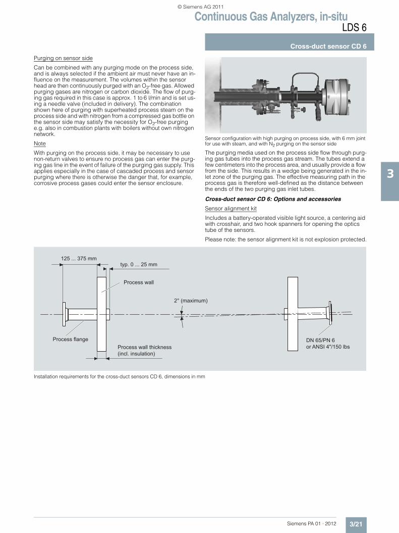
Purging on sensor side
Can be combined with any purging mode on the process side, and is always selected if the ambient air must never have an in-fluence on the measurement. The volumes within the sensor head are then continuously purged with an O2-free gas. Allowed purging gases are nitrogen or carbon dioxide. The flow of purg-ing gas required in this case is approx. 1 to 6 l/min and is set us-ing a needle valve (included in delivery). The combination shown here of purging with superheated process steam on the process side and with nitrogen from a compressed gas bottle on the sensor side may satisfy the necessity for O2-free purging e.g. also in combustion plants with boilers without own nitrogen network.
Note
With purging on the process side, it may be necessary to use non-return valves to ensure no process gas can enter the purg-ing gas line in the event of failure of the purging gas supply. This applies especially in the case of cascaded process and sensor purging where there is otherwise the danger that, for example, corrosive process gases could enter the sensor enclosure.
Sensor configuration with high purging on process side, with 6 mm joint for use with steam, and with N2 purging on the sensor side
The purging media used on the process side flow through purg-ing gas tubes into the process gas stream. The tubes extend a few centimeters into the process area, and usually provide a flow from the side. This results in a wedge being generated in the in-let zone of the purging gas. The effective measuring path in the process gas is therefore well-defined as the distance between the ends of the two purging gas inlet tubes.
Cross-duct sensor CD 6: Options and accessories
Sensor alignment kit
Includes a battery-operated visible light source, a centering aid with crosshair, and two hook spanners for opening the optics tube of the sensors.
Please note: the sensor alignment kit is not explosion protected.
Installation requirements for the cross-duct sensors CD 6, dimensions in mm
125 ... 375 mmtyp. 0 ... 25 mm
2° (maximum)
DN 65/PN 6or ANSI 4"/150 lbs
Process wall
Process wall thickness(incl. insulation)
Process flange
PA01_2012_EN.book Seite 21 Freitag, 30. September 2011 11:09 11
© Siemens AG 2011

Continuous Gas Analyzers, in-situLDS 6
Cross-duct sensor CD 6
3/22 Siemens PA 01 · 2012
3
Purging air blower
Two purging air blowers are required to purge the sensor heads. Both 230 V AC and 115 V AC versions can be ordered.
Sensor configuration with purging air blower
Flow cell (available on special application)
For implementation of measuring configurations with bypass mode. The cell consists of a stainless steel tube whose internal surfaces are coated with PTFE to minimize surface effects. With an effective measuring path of 1 m, the inner volume is only 1.2 l, and fast gas displacement times can therefore be achieved. The flow of sample gas can be from the ends or from the center of the tube, since appropriate 6 mm joints are present here. The flow cell can be ordered in four configurations:• Unheated, including assembly for wall mounting• Unheated, including assembly for wall mounting and a 19"
housing with an air jet pump with a delivery rate of max. 30 l/min
• As above, but can be heated up to approx. 200 °C • As above, but can be heated up to approx 200 °C and
mounted on a rack with wheels and integrated 19" frame
Optical bandpass filter
Serves to protect the light-sensitive detector in the receiver unit of the sensor from saturation by IR background radiation. Is used with measurements in very hot process gases (T > 1 000 °C) or with unavoidable appearances of flames in the measurement path.
Ø12
Electrical connections:230 V AC 50 Hzor 115 V AC 60 HzPower consumpt.: ~500 W
1 ¼” hose connection
Airfilter
CD 6 sensor forblower air purging
PA01_2012_EN.book Seite 22 Freitag, 30. September 2011 11:09 11
© Siemens AG 2011

Continuous Gas Analyzers, in-situLDS 6
Cross-duct sensor CD 6
3/23Siemens PA 01 · 2012
3
■ Technical specifications
Cross-duct sensor CD 6
Accessories
Hybrid and sensor cables
General information
Design Transmitter and detector units, connected by a sensor cable
Materials Stainless steel Installation Horizontally to the optical axis,
perpendicular or parallel to the gas flow
Laser protection class Class 1, safe to the eye Explosion protection Optional, acc. to ATEX II 1 G Ex ia
IIC T4, ATEX II 1 D Ex iaD 20 IP65 T135 °CA defined leak rate can only be guaranteed when using high-pressure window flanges. Other-wise it may be necessary for the owner to carry out an evaluation in accordance with ATEX (DEMKO 06 ATEX 139648X [17]).
Design, enclosure
Degree of protection IP65Dimensions Diameter: 163, L: 395 mm Purging gas tube in mm 400 (370 net) x 44 x 40
800 (770 net) x 44 x 40 1 200 (1 170 net) x 44 x 40
Weight 2 x approx. 11 kg Mounting DN 65/PN 6 or ANSI 4"/150Please note:• For purging tubes with a length of 800 and 1 200 mm, the wall thickness
must not exceed 200 mm with DN 65/PN 6 connections. To carry out measurements with thicker walls, please contact Siemens.
• The optimum adjustment of the flanges can change with high differences in temperature depending on the type of assembly.
Electrical characteristics
Power supply 24 V DC, supply from central unit via hybrid cable
Power consumption < 2 W during operation Climatic conditions
Ambient temperature -30 ... +70 °C during operation, -40 ... +70 °C during storage and transportation
Humidity < 95 % RH, above dew point Pressure 800 ... 1 100 hPaTemperature range on the sensor side of the process interface (connection plate)
-20 … +70 °C
Measuring conditions
Measurement path 0.3 ... 12 m (other lengths on request)
Gas temperatures 0 ... 1 200 °C, application-dependent
Gas pressure General: 1 013 ± 50 hPaWith high-pressure window flanges: CO/CO2 application KD: 800 ... 1 400 hPaHigh-pressure O2 application AP: 950 ... 5 000 hPa
Dust load The influence of dust is very com-plex and depends on the path length and particle size. The opti-cal damping increases exponen-tially at longer path lengths. Smaller particles also have a large influence on the optical damping. With high dust load, long path length and small parti-cle size, the technical support at Siemens should be consulted.
Purging
Nitrogen is permissible as the purging gas for the sensor side. Nitrogen, steam, air and gases which are not subject to the pressure equipment directive Cat. 2 are permissible as purging gases for the process side.
Purging with instrument air, N2
• Pressure at purging inlet 2 000 ... 8 000 hPa
• Max. overpressure in the sensor < 500 hPa
• Quality
- Instrument air Free of oil and water
- Nitrogen Purity better than 99.7 %. For oxy-gen measurements, and an O2 content < 0.01 % in the purging gas (optical path length ≥ 1 m, min. 5 % oxygen in the process gas)
• Maximum flow rate 500 l/min
• Dew point Benchmark: < -10 °C, condensa-tion on the optics must be avoided
Blower purging
• Maximum counter pressure 40 hPa
• Maximum flow rate 850 l/min
• Power consumption 370 W
• Degree of protection (fan) IP54, cover required to protect against rain
Steam purging
• Steam conditioning Overheated
• Maximum temperature 240 °C
• Minimum pressure > 4 000 hPa
• Maximum pressure 16 000 hPa, refers to a volume flow of approx. 1 100 l/min
General information
Configuration hybrid cable Two optical fibers and two twisted copper wires in one cable for 24 V DC. Single-mode optical fiber configured at both ends with E2000 angle connectors. Multi-mode optical fiber configured at both ends with SMA connectors.
Cable sheath Oil-resistant polyurethane
Dimensions • For > 500 m, an external power supply must be additionally or-dered
• For installation in hazardous zones, non-intrinsically-safe ca-bles have to be spatially sepa-rated from intrinsically-safe lines
• Diameter < 8 mm
• Length • Use in non-hazardous and Ex Zone 2: Up to 700 m
• Use in Ex Zone 0 and Zone 1: Up to 250 m
Impact resistance 200 N/cm
Maximum tensile strength 500 N
Minimum bending radius 10 cm
Climatic conditions
Ambient temperature -40 ... +80 °C during operation
Humidity < 95 % rel. humidity, above dew point (in operation and storage)
PA01_2012_EN.book Seite 23 Freitag, 30. September 2011 11:09 11
© Siemens AG 2011

Continuous Gas Analyzers, in-situLDS 6
Cross-duct sensor CD 6
3/24 Siemens PA 01 · 2012
3
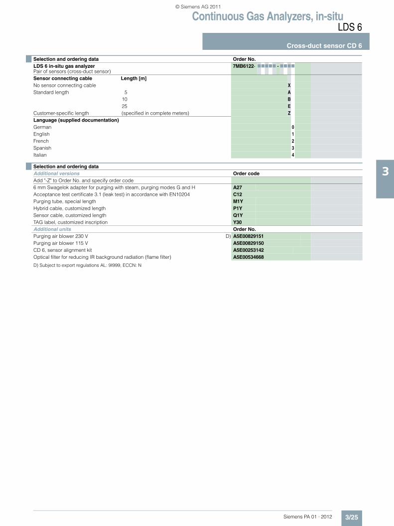
Selection and ordering data Order No.LDS 6 in-situ gas analyzerPair of sensors (cross-duct sensor)
7MB6122- 77777 - 7777
Explosion protectionWithout 0According to ATEX II 1 G Ex ia IIC T4, ATEX II 1 D Ex iaD 20 IP65 T135 °C 1Sensor type Measured componentStandard cross-duct sensor O2 A
All gases except O2 WPurging, process side Sensor sideWithout purging Without purging A
Air or N2, 1 ... 2 l/min;incl. needle valve, 6 mm Swagelok
B
Instrument air or N2 Reduced flow: 0 ... 120 l/minincl. needle valve, 6 mm Swagelok
Without purging C
Air or N2, 1 ... 2 l/min;incl. needle valve, 6 mm Swagelok
D
Air or N2 Increased flow: 200 ... 500 l/minincl. 6 mm Swagelok
Without purging E
Air or N2, 1 ... 2 l/min;incl. needle valve, 6 mm Swagelok
F
Air, fan or steam;high flow: > 500 l/minincl. 1¼" hose adapter
Without purging G
Air or N2, 1 ... 2 l/min;incl. needle valve, 6 mm Swagelok
H
Purging tubes, materialNo purging tubes 0Stainless steel, EN 1.4432/316L 1Purging tubes, lengthNo purging tubes 0400 mm 1800 mm 21 200 mm 375 mm, e.g. for engine test rigs 4Process connectionStainless steel flange (EN 1.4404/316L), dimensions acc. to DN 65/PN 6 0Stainless steel flange (EN 1.4404/316L), dimensions acc. to ANSI 4"/150 lbs 1Stainless steel flange (EN 1.4404/316L), dimensions acc. to DN 65/PN 6, including enclosed welding flanges, e.g. for engine test rigs
2
Pressure-resistant window flange (EN 1.4404/316L, borosilicate glass), DN 65/PN 6 3Pressure-resistant window flange (EN 1.4404/316L, borosilicate glass), DN 80/PN 16 4Pressure-resistant window flange (EN 1.4404/316L, borosilicate glass), ANSI 4"/150 lbs 5Hybrid cable Length [m]No hybrid cable XStandard length 5 A
10 B25 E40 G50 H
Customized length (specified in complete meters) Z
PA01_2012_EN.book Seite 24 Freitag, 30. September 2011 11:09 11
© Siemens AG 2011
Continuous Gas Analyzers, in-situLDS 6
Cross-duct sensor CD 6
3/25Siemens PA 01 · 2012
3
D) Subject to export regulations AL: 9I999, ECCN: N
Sensor connecting cable Length [m]No sensor connecting cable XStandard length 5 A
10 B25 E
Customer-specific length (specified in complete meters) ZLanguage (supplied documentation)German 0English 1French 2Spanish 3Italian 4
Selection and ordering data Order No.LDS 6 in-situ gas analyzerPair of sensors (cross-duct sensor)
7MB6122- 77777 - 7777
Selection and ordering dataAdditional versions Order codeAdd "-Z" to Order No. and specify order code6 mm Swagelok adapter for purging with steam, purging modes G and H A27Acceptance test certificate 3.1 (leak test) in accordance with EN10204 C12Purging tube, special length M1YHybrid cable, customized length P1YSensor cable, customized length Q1YTAG label, customized inscription Y30Additional units Order No.Purging air blower 230 V D) A5E00829151Purging air blower 115 V A5E00829150CD 6, sensor alignment kit A5E00253142Optical filter for reducing IR background radiation (flame filter) A5E00534668
PA01_2012_EN.book Seite 25 Freitag, 30. September 2011 11:09 11
© Siemens AG 2011

Continuous Gas Analyzers, in-situLDS 6
Cross-duct sensor CD 6
3/26 Siemens PA 01 · 2012
3
■ Dimensional drawings
Cross-duct sensor CD 6, moderate purging (instrument air), version according to Order No. 7MB6122-**C1*-0***, dimensions in mm
Cross-duct sensor CD 6, increased purging (instrument air), version according to Order No. 7MB6122-**E1*-0***, dimensions in mm
370
(770
, 1 1
70)
395
105
400
(800
, 1 2
00)
Ø 163
Ø 44.5 at 400 lengthØ 54 at 800, 1 200 length
Process flange(provided by customer)
Ø 6 mm fitting for
370
(770
, 1 1
70)
400
(800
, 1 2
00)
395
105
Ø 163
Ø 44.5 at 400 lengthØ 54 at 800, 1 200 length
Process flange(provided by customer)
PA01_2012_EN.book Seite 26 Freitag, 30. September 2011 11:09 11
© Siemens AG 2011
Continuous Gas Analyzers, in-situLDS 6
Cross-duct sensor CD 6
3/27Siemens PA 01 · 2012
3
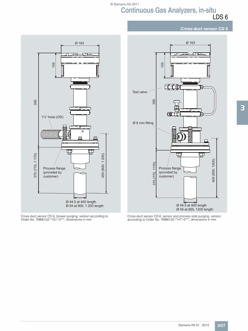
Cross-duct sensor CD 6, blower purging, version according to Order No. 7MB6122-**G1*-0***, dimensions in mm
Cross-duct sensor CD 6, sensor and process side purging, version according to Order No. 7MB6122-**H1*-0***, dimensions in mm
400
(800
, 1 2
00)
370
(770
, 1 1
70)
395
Ø 163
105
Ø 44.5 at 400 lengthØ 54 at 800, 1 200 length
Process flange(provided by customer)
1¼” hose (OD)
395
Ø 163
105
370
(770
, 117
0)
400
(800
, 120
0)
Ø 44.5 at 400 lengthØ 54 at 800, 1200 length
Ø 6 mm fitting
Test valve
Process flange(provided by customer)
PA01_2012_EN.book Seite 27 Freitag, 30. September 2011 11:09 11
© Siemens AG 2011

Continuous Gas Analyzers, in-situLDS 6
Cross-duct sensor CD 6
3/28 Siemens PA 01 · 2012
3
Cross-duct sensor CD 6, purged version according to Order No. 7MB6122-*WC14-2***, dimensions in mm
CD 6 high-pressure sensor for oxygen, dimensions in mm
431
Ø 163
105
High pressure flange
Check valve
Fittingfor Ø 6 mmOD hose
PA01_2012_EN.book Seite 28 Freitag, 30. September 2011 11:09 11
© Siemens AG 2011
Continuous Gas Analyzers, in-situLDS 6
Documentation
3/29Siemens PA 01 · 2012
3
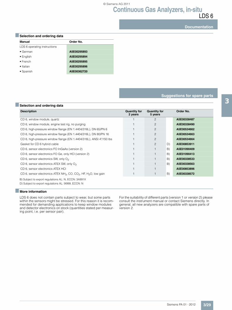
■ Selection and ordering data
■ Selection and ordering data
B) Subject to export regulations AL: N, ECCN: 3A991XD) Subject to export regulations AL: 9I999, ECCN: N
■ More information
LDS 6 does not contain parts subject to wear, but some parts within the sensors might be stressed. For this reason it is recom-mended for demanding applications to keep window modules and detector electronics on stock (quantities stated per measur-ing point, i.e. per sensor pair).
For the suitability of different parts (version 1 or version 2) please consult the instrument manual or contact Siemens directly. In general, all new analyzers are compatible with spare parts of version 2.
Manual Order No.
LDS 6 operating instructions
• German A5E00295893
• English A5E00295894
• French A5E00295895
• Italian A5E00295896
• Spanish A5E00362720
Suggestions for spare parts
Description Quantity for 2 years
Quantity for 5 years
Order No.
CD 6, window module, quartz 1 2 A5E00338487
CD 6, window module, engine test rig, no purging 1 2 A5E00338490
CD 6, high-pressure window flange (EN 1.4404/316L), DN 65/PN 6 1 2 A5E00534662
CD 6, high-pressure window flange (EN 1.4404/316L), DN 80/PN 16 1 2 A5E00534663
CD 6, high-pressure window flange (EN 1.4404/316L), ANSI 4"/150 lbs 1 2 A5E00534664
Gasket for CD 6 hybrid cable 1 2 D) A5E00853911
CD 6, sensor electronics FO InGaAs (version 2) 1 1 B) A5E01090409
CD 6, sensor electronics FO Ge, only HCl (version 2) 1 1 B) A5E01090413
CD 6, sensor electronics SW, only O2 1 1 B) A5E00338533
CD 6, sensor electronics ATEX SW, only O2 1 1 B) A5E00338563
CD 6, sensor electronics ATEX HCI 1 1 A5E00853896
CD 6, sensor electronics ATEX NH3, CO, CO2, HF, H2O, low gain 1 1 B) A5E00338572
PA01_2012_EN.book Seite 29 Freitag, 30. September 2011 11:09 11
© Siemens AG 2011