Contingency Action Planfiles.dnr.state.mn.us/.../v2/...contingency_action_plan_v5_may2017.pdf ·...
23
NorthMet Project Contingency Action Plan for the Flotation Tailings Basin Version 5 Issue Date: May 15, 2017
Transcript of Contingency Action Planfiles.dnr.state.mn.us/.../v2/...contingency_action_plan_v5_may2017.pdf ·...

NorthMet Project
Contingency Action Plan
for the Flotation Tailings Basin
Version 5
Issue Date: May 15, 2017

Date: May 15, 2017
NorthMet Project
Contingency Action Plan for the Flotation
Tailings Basin
Version: 5 Contents
Table of Contents
1.0 Contingency Action Plan Summary ................................................................................................. 1
1.1 Purpose ........................................................................................................................................ 1
1.2 Notification Flowchart................................................................................................................. 1
1.3 Site Description ........................................................................................................................... 2
1.4 Observational Method ................................................................................................................. 2
1.5 Supporting Documentation .......................................................................................................... 3
1.6 Outline ......................................................................................................................................... 4
2.0 Unusual, Hazardous and/or Emergency Conditions Warning Signs and Response Actions ........... 5
2.1 Visual Warning Signs .................................................................................................................. 6
2.2 Monitoring Instrument Warning Signs ........................................................................................ 6
3.0 Contacts ........................................................................................................................................... 7
4.0 Notification Procedures ................................................................................................................... 9
4.1 Internal Notification Procedures .................................................................................................. 9
4.2 External Notification Procedures ................................................................................................ 9
5.0 Emergency Mobilization Procedures ............................................................................................. 11
6.0 Emergency Evacuation Procedures ................................................................................................ 13
Revision History ......................................................................................................................................... 14
List of Tables .............................................................................................................................................. 15
List of Figures ............................................................................................................................................. 15
List of Large Figures ................................................................................................................................... 15
List of Large Tables .................................................................................................................................... 15

Date: May 15, 2017
NorthMet Project
Contingency Action Plan for the Flotation
Tailings Basin
Version: 5 Page 1
1.0 Contingency Action Plan Summary
1.1 Purpose
The purpose of the Flotation Tailings Basin (FTB) Contingency Action Plan (CAP) is to:
identify potential basin failure modes that could occur during construction events and
during routine operations; conditions that if left undetected and unresolved could
instigate instability of basin dams
proactively identify contingency plans (i.e., operation change, design change if
needed) for each potential failure mode, if observed
identify instrumentation and monitoring that confirms acceptability of construction
and operating activities, and proactively alerts construction, operations, and
management personnel to basin conditions that if left unresolved could initiate a
potential failure mode
define responsibilities and provide procedures for responding to unexpected and
potentially hazardous conditions threatening the integrity and performance of the FTB
This document will evolve throughout the permitting, operating, reclamation, and postclosure
maintenance phases of the NorthMet Project (Project). It will be reviewed and updated as
necessary in conjunction with changes that occur in facility operating and maintenance
methods or requirements. Each revision will be provided to the Department of Natural
Resources (DNR) dam safety permitting personnel for informational purposes such that they
remain fully informed as plan updates are incorporated. Any plan updates that may affect
permit conditions will be discussed with dam safety permitting personnel. A Revision
History is included at the end of the document.
This CAP is intended to be a stand-alone guide to initial response to emergency conditions
that could potentially develop at the FTB. As with any emergency condition, ongoing real-
time decision-making will be required once the situation is assessed. Poly Met Mining, Inc.
(PolyMet) will establish and maintain a project-wide emergency action plan (EAP) that
should be referenced in the event of other potential conditions such as severe weather (i.e.,
tornado) or fire that are not a part of this plan and which do not constitute a significant or
ongoing threat to the FTB.
1.2 Notification Flowchart
The Notification Flowchart (Large Figure 1) summarizes the sequence of actions required
during a situation involving threat of dam failure. Contact lists are provided in Section 3.0.
Notification procedures for other hazardous situations are described in Section 0.
Date: May 15, 2017
NorthMet Project
Contingency Action Plan for the Flotation
Tailings Basin
Version: 5 Page 2
1.3 Site Description
The FTB is a tailings basin located on the PolyMet Plant Site. The Plant Site is located south
of the Embarrass River in St. Louis County. The area between the FTB and the Embarrass
River is sparsely populated forest.
Personnel responsible for FTB management are:
Operations Contact - Beneficiation Division Manager or designee – Responsible for
overall FTB design, planning, operations, maintenance, and monitoring. The plant site
will be staffed full-time during operations and alternate contacts shall be designated
to support the Beneficiation Division Manager in CAP implementation.
Design Engineer (an independent consultant retained specially for dam safety
expertise and a registered engineer) – Responsible for performance monitoring data
analysis and interpretation, dam safety inspection and reporting assistance, tailings
dam planning and design assistance, and permitting assistance.
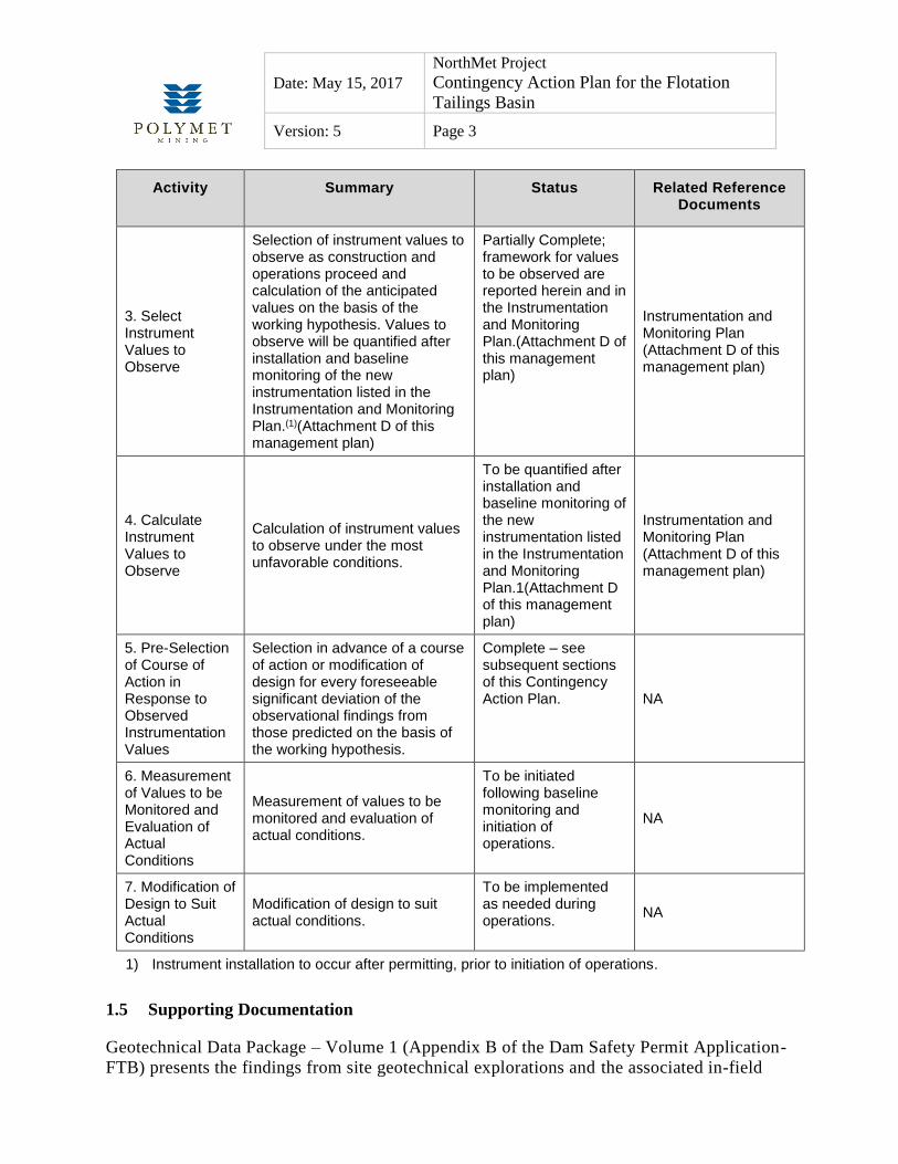
1.4 Observational Method
The Observational Method as stated by Peck (1969) in his Rankine Lecture is the method by
which the integrity of the Tailings Basin dams will be monitored and basin operations and/or
design adjusted as needed in response to observations. The steps in the Observational
Method and their status as of the writing of this version of the Contingency Action Plan are
summarized in Table 1-1.
Table 1-1 Observational Method
Activity Summary Status Related Reference Documents
1. Geotechnical Exploration
Geotechnical exploration sufficient to establish at least the general nature, pattern and properties of the deposits, but not necessarily in detail.
Complete Geotechnical Data Package – Volume 1 (Appendix B of the Dam Safety Permit Application-FTB)
2. Initial Design
Establishment of the design based on a working hypothesis of behavior anticipated under the most probable conditions.
Complete See Geotechnical Data Package – Volume 1 (Appendix B of the Dam Safety Permit Application-FTB)
Date: May 15, 2017
NorthMet Project
Contingency Action Plan for the Flotation
Tailings Basin
Version: 5 Page 3
Activity Summary Status Related Reference Documents
3. Select Instrument Values to Observe
Selection of instrument values to observe as construction and operations proceed and calculation of the anticipated values on the basis of the working hypothesis. Values to observe will be quantified after installation and baseline monitoring of the new instrumentation listed in the Instrumentation and Monitoring Plan.(1)(Attachment D of this management plan)
Partially Complete; framework for values to be observed are reported herein and in the Instrumentation and Monitoring Plan.(Attachment D of this management plan)
Instrumentation and Monitoring Plan (Attachment D of this management plan)
4. Calculate Instrument Values to Observe
Calculation of instrument values to observe under the most unfavorable conditions.
To be quantified after installation and baseline monitoring of the new instrumentation listed in the Instrumentation and Monitoring Plan.1(Attachment D of this management plan)
Instrumentation and Monitoring Plan (Attachment D of this management plan)
5. Pre-Selection of Course of Action in Response to Observed Instrumentation Values
Selection in advance of a course of action or modification of design for every foreseeable significant deviation of the observational findings from those predicted on the basis of the working hypothesis.
Complete – see subsequent sections of this Contingency Action Plan. NA
6. Measurement of Values to be Monitored and Evaluation of Actual Conditions
Measurement of values to be monitored and evaluation of actual conditions.
To be initiated following baseline monitoring and initiation of operations.
NA
7. Modification of Design to Suit Actual Conditions
Modification of design to suit actual conditions.
To be implemented as needed during operations.
NA
1) Instrument installation to occur after permitting, prior to initiation of operations.
1.5 Supporting Documentation
Geotechnical Data Package – Volume 1 (Appendix B of the Dam Safety Permit Application-
FTB) presents the findings from site geotechnical explorations and the associated in-field

Date: May 15, 2017
NorthMet Project
Contingency Action Plan for the Flotation
Tailings Basin
Version: 5 Page 4
and in-laboratory test data, and the seepage and slope stability model outcomes for the most
probable geotechnical slope stability conditions and the unfavorable slope conditions
evaluated to date.
Design of the FTB as guided by findings presented in the Geotechnical Data Package is
presented in this Flotation Tailings Management Plan which provides a full description of the
FTB.
The Flotation Tailings Basin Instrumentation and Monitoring Plan (Attachment D of this
management plan) presents the plan for instrumentation installation to be completed after
permitting but prior to initiation of basin operations. Following instrumentation installation,
baseline instrument monitoring data will be gathered and, in conjunction with the additional
geotechnical data gathered during instrument installation; seepage and slope stability models
will be updated and typical instrument values at each instrument location will be established
for normal and high pond conditions. Threshold values will be documented and the initial
actions to be taken in response to data trends toward threshold values will be reviewed and
updated as needed (Figure 1-1).
Figure 1-1 Instrumentation Timeline
The details of the instrumentation and monitoring (instrument types, locations, threshold
values) will be retained within the Instrumentation and Monitoring Plan, with periodic
updates to that plan as needed as instrumentation is installed and/or replaced, and as
construction and operations of the FTB proceeds.
1.6 Outline
The outline of this document is:
Section 1.0 Contingency Action Plan Summary.
Section 2.0 Warning signs of unusual, hazardous, or emergency conditions associated with
construction and operation of the FTB, and response actions.
Section 3.0 Internal and external emergency notification procedures.
Section 5.0 Emergency Mobilization Procedures.
Section 6.0 Emergency Evacuation Procedures.

Date: May 15, 2017
NorthMet Project
Contingency Action Plan for the Flotation
Tailings Basin
Version: 5 Page 5
2.0 Unusual, Hazardous and/or Emergency Conditions Warning Signs and Response
Actions
Unusual, hazardous, and/or emergency conditions warning signs may be visually evident
during routine or special tailings basin inspections, and/or may be evidenced by changed
monitoring values in piezometers, inclinometers, and/or survey monuments. Some unusual
conditions may not warrant an emergency response, but require prompt investigation and
resolution. Events which may cause unusual, hazardous, and/or emergency conditions may
include (but are not limited to):
Natural weather events, which could impact pond levels or cause erosion, including:
o high precipitation event
o significant snowmelt in combination with high precipitation event
Operational disruptions, which could cause erosion or impact the phreatic surface
within the dam, including:
o an unrepaired pipe break or
o prolonged pump stoppage
Construction changes, which could impact the phreatic surface of the dam or create
excess pore water pressures within the dam, including:
o increase in the rate of construction
o over steepening of dam slopes
Unusual conditions will typically involve an investigation, intensified monitoring, inspecting
and/or testing, and defining and implementing possible corrective measures. Some conditions
represent a potential emergency if sustained or allowed to progress. In such cases it will be
necessary to discuss and define a response plan, at the site, under the direction of the
Operations Contact, and then to implement the plan. The first actions in the event of any
emergency condition are:
initiate the appropriate chain of communications
check that all persons who could possibly be affected are safe
immediately undertake the appropriate response actions
Sections 3, 4 and 5 describe actions to be initiated if an emergency situation occurs. The
following sections list potential visual and monitoring instrument warning signs.

Date: May 15, 2017
NorthMet Project
Contingency Action Plan for the Flotation
Tailings Basin
Version: 5 Page 6
2.1 Visual Warning Signs
Large Table 1 provides a listing of visual warning signs and initial response actions for
unusual, hazardous, and/or emergency conditions that could develop at the Tailings Basin. It
is important to note that each condition is unique and that seemingly harmless conditions
could quickly progress into something more serious if timely and appropriate action is not
taken. To detect visual warning signs, daily and weekly inspections, semi-annual inspections,
and inspections after unusual events/observations will be carried out as specified in this
Flotation Tailings Management Plan.
2.2 Monitoring Instrument Warning Signs
Large Table 2 provides a listing of monitoring instrument warning signs and initial response
actions for unusual, hazardous, and/or emergency conditions that could develop at the
Tailings Basin. As with visual warning signs, it is important to note that each monitoring
instrument warning sign condition is unique and that seemingly harmless conditions could
quickly progress into something more serious if timely and appropriate action is not taken.
Instrumentation data collection will in many cases be automated, allowing for real -time
notification of data that is approaching pre-defined threshold values. Instruments that are not
automated (e.g., alignment hubs, some inclinometers and some piezometers) will be read at
the specified frequency. Further detail is provided in the Instrumentation and Monitoring
Plan (Attachment D of this management plan).

Date: May 15, 2017
NorthMet Project
Contingency Action Plan for the Flotation
Tailings Basin
Version: 5 Page 7
3.0 Contacts
Emergency contacts are summarized in Tables 3-1 through 3-3. These tables will be updated
prior to initiation of basin operations and on a routine basis as company personnel and
responsibilities change.
Table 3-1 NorthMet Tailings Basin Structural Integrity Emergency Contact List
Emergency Contact Name Mobile Office
Mining Manager (as alternate to
General Manager)
Jim Tieberg 218-248-0952 218-471-2165
Operations Contact (Manager of
Operations and Development)
Dave Hughes TBD 218-471-2158
PolyMet Mining Environmental
Compliance Manager
Kevin Pylka 218-750-2054 218-471-2162
Environmental Site Director Christie Kearney 218-461-7746 218-471-2163
Director of Environmental
Permitting and Compliance
Jennifer Saran 651-600-5457 651-389-4108
Design Engineer Tom Radue 952-240-4051 952-832-2600
Emergency Health and Safety
Fire/Ambulance/Police –
Dependent on Incident Severity
N/A 911 911
Hospital – Grand Itasca Clinic
and Hospital
General Number N/A 218-326-3401
Government Agencies
Minnesota Duty Officer 800-422-0798
National Response Center 800-424-8802
US EPA Region V 312-353-2318
Minnesota Pollution Control Agency (24 hrs) 612-296-8100 or
612-296-6300
Minnesota Emergency Response Commission 612-643-3000

Date: May 15, 2017
NorthMet Project
Contingency Action Plan for the Flotation
Tailings Basin
Version: 5 Page 8
Table 3-2 City of Hoyt Lakes Emergency Contact List
Title Name Phone Email
Police Chief Tim Soular 218-225-2000 [email protected]
Sergeant Heather Krueger 218-225-2000 [email protected]
911 Emergency
Communications
Emergency
Non-Emergency
911
218-742-9825
N/A
Residents and/or businesses in affected inundation area will be added to this list
Table 3-3 St Louis County Emergency Contact List
Title Name Phone Email
Sheriff Ross Litman 218-726-2340 [email protected]
Undersheriff Dave Philips 218-726-2340 [email protected]
911 Emergency
Communications
Emergency
Non-Emergency
911
218-727-8770
Mine Inspector Steve Manninen 218-742-9840 [email protected]
PolyMet will work with local emergency agency personnel to establish and confirm the list
of residences who may need to be contacted in case of some emergencies at the FTB, the
means to be used for contact, and the assignment of responsibility for maintenance of the
contact list.
Date: May 15, 2017
NorthMet Project
Contingency Action Plan for the Flotation
Tailings Basin
Version: 5 Page 9
4.0 Notification Procedures
The top priority in case of imminent or actual dam failure is to warn and evacuate people in
downstream areas. Large Figure 1 presents the notification procedures for an emergency
involving threat of dam failure. Attachment A describes responsible persons and their
responsibilities for notification, emergency operations and repairs, and post-emergency
action. Section 6.0 describes emergency evacuation procedures.
Emergency notification procedures vary depending on the condition/s existent that prompt
the notification and can be divided into three levels:
Level 1 – Condition that does not warrant emergency response but requires prompt
investigation and resolution.
Level 2 – Potential emergency if condition is sustained or allowed to progress; requires
response plan.
Level 3 – Imminent or actual failure requiring partial or complete evacuation, emergency
communications and response actions.
Level 1, Level 2, and Level 3 conditions that could occur at the Tailings Basin are listed in
Large Table 1 and Large Table 2.
4.1 Internal Notification Procedures
The notification procedures for Level 1 and Level 2 conditions are:
the person first noticing a Level 1 or Level 2 condition will notify the Operations
Contact and initiate responses and intensified monitoring
the Operations Contact will notify the Design Engineer as appropriate
The notification procedure for Level 3 conditions are:
the person first noticing a Level 3 condition will notify the General Manager, the
Operations Contact and initiate responses immediately, and
The Operations Contact will notify the Design Engineer.
4.2 External Notification Procedures
No external notification is required for Level 1 or 2 conditions. The notification procedure
for a Level 3 condition is as follows:

Date: May 15, 2017
NorthMet Project
Contingency Action Plan for the Flotation
Tailings Basin
Version: 5 Page 10
If the condition presents the threat of dam failure, the notification procedures shown
in Large Figure 1 and the evacuation procedures presented in Section 6.0 will be
implemented
Once Level 3 actions are implemented, but in no case longer than 4 hours after the
occurrence, the Operations Contact will notify the responsible regulatory personnel at
the DNR and/or Minnesota Pollution Control Agency (as appropriate to permit
coverage and compliance requirements)
Notification will occur first via telephone, with follow-up E-mail or other written
correspondence to document initial and any follow-up telephone conversations
In the event of an emergency situation resulting from actual or potentially imminent dam
failure, the Operations Contact will also initiate evacuation procedures as described in
Section 6.0.
Copies of this FTB Contingency Action Plan and the plant-wide Emergency Action Plan
shall be kept in the office of the Operations Contact.

Date: May 15, 2017
NorthMet Project
Contingency Action Plan for the Flotation
Tailings Basin
Version: 5 Page 11
5.0 Emergency Mobilization Procedures
All those involved in response, after first having communicated with the appropriate parties,
should consider two types of actions as first steps in the response, with respect to the
protection of human life and health, environment and property:
What can be done to prevent the situation from worsening?
What can be done to reduce the consequences of the impending or actual failure?
Any such action must be presented to the Operations Contact who will decide on its
implementation in consultation with the Design Engineer. Most obvious mobilization
requirements associated with Level 2 and Level 3 conditions are detailed in Table 5-1.
Table 5-1 FTB Mobilization Plan for Level 2 or 3 Situations
Component Failure
Level 2 Condition Level 3 Condition
Failure of a dam (during construction and/or routine operations).
Planning for mobilization of earthmoving equipment, pumps and pipelines, as well as lowering of the pond level may be necessary, after all communications are carried out.
Immediate mobilization of earthmoving equipment, pumps, pipelines, power generator(s) available at site locations, and lights, will most likely be necessary. Immediate lowering of the pond level will typically be necessary.
Failure of a pump station.
After the repair work is initiated, plan for mobilization of pumping equipment if the timing for repairs would affect the pumping needs.
Immediate mobilization of pumping equipment and, if required, the availability of a power generator may be necessary.
Failure of a pipeline.
Initiate pipe or pipe section replacement.
Initiate chain of communications after initiating pipe or pipe section replacement.
Localized power failure.
Identify systems affected. Prepare for cessation of tailings deposition if power outage exceeds 24 hours.
Identify systems affected. Cease tailings deposition if power outage exceeds 24 hours.
Regional power failure.
No action required. FTB operations cease in absence of power.
No action required. FTB operations cease in absence of power.
In conjunction with Level 2 and Level 3 Conditions it will be the responsibility of the
Operations Contact to compile a list of the specific equipment needs, size/type, source
(company, name, contact information), and availability to respond to component failure. The
list shall be populated prior to the initiation of basin operations and be reviewed and updated
on an annual basis thereafter. This is so that a timely response can be made in the event that
emergency mobilization is required. For emergency response equipment that does not have
local 24-hour 7-day-per-week availability, provisions shall be made for permanent on-site
stationing of the equipment. Primary emergency response equipment will typically consist of

Date: May 15, 2017
NorthMet Project
Contingency Action Plan for the Flotation
Tailings Basin
Version: 5 Page 12
on-site earthwork equipment, mobile pumping systems and supplementary piping and power
supply, and mobile/emergency lighting carts with power supply.

Date: May 15, 2017
NorthMet Project
Contingency Action Plan for the Flotation
Tailings Basin
Version: 5 Page 13
6.0 Emergency Evacuation Procedures
During operations, personnel will be on-site 24 hours a day, 7 days per week. Personnel will
therefore be able to review conditions and monitor for changing conditions. Additionally,
monitoring instrumentation is planned to be automated by a remote monitoring system,
which includes thresholds and automated alarms data trends toward or falls outside of pre-
established thresholds.
In the event of a failure of the FTB dam, residences located between the FTB and the
Partridge River could be flooded. The Dam Break Analysis (Attachment H of this
Management Plan) presents an inundation map and describes approximate floodwave travel
times. The Dam Break Analysis indicates that there would be adequate time to provide
emergency warning. There is some chance that a problem may not be identified, recognized,
or responded to in a timely manner. Therefore, any early warning signs will be treated with
the highest level of priority. If evacuation notices are given, it will be understood that the
notice is at minimum due to a prudent level of caution and those potentially affected will be
instructed to evacuate without delay.
A list of residences and businesses having the potential to be impacted by a dam break will
be assembles and attached to this CAP prior to the start of FTB operations. As noted
previously, PolyMet will work with local emergency agency personnel to establish and
confirm the list of residences who may need to be contacted, and the means to be used for
contact.

Date: May 15, 2017
NorthMet Project
Contingency Action Plan for the Flotation
Tailings Basin
Version: 5 Page 14
Revision History
Date Version Description
10/31/2011 1 Initial release
12/07/2012 2
Dam Break Analysis results incorporated by reference.
FTB Dam Failure Notification Flowchart placeholder added.
Outline expanded for development during DNR Dam Safety permitting.
04/12/2013 3
Revisions made to address DNR comments that not all situations are Emergencies. Hence, renamed document Contingency Action Plan and expanded on contingency actions to be implemented in response to various potential on-site conditions.
07/11/2016 4 Revisions made to submit for permitting and to include Notification Flowchart (Large Figure 1).
05/15/2017 5 Revisions made to add detail to Observational Method and Construction Phase warning signs and response actions.

Date: May 15, 2017
NorthMet Project
Contingency Action Plan for the Flotation
Tailings Basin
Version: 5 Page 15
List of Tables
Table 1-1 Observational Method ................................................................................................. 2 Table 3-1 NorthMet Tailings Basin Structural Integrity Emergency Contact List ..................... 7
Table 3-2 City of Hoyt Lakes Emergency Contact List .............................................................. 8 Table 3-3 St Louis County Emergency Contact List .................................................................. 8 Table 5-1 FTB Mobilization Plan for Level 2 or 3 Situations .................................................. 11
List of Figures
Figure 1-1 Instrumentation Timeline ........................................................................................ 4
List of Large Figures
Large Figure 1 FTB Dam Failure Notification Flowchart
List of Large Tables
Large Table 1 Visual Warning Signs
Large Table 2 Instrumentation Warning Signs

Large Tables

Large Table 1 Visual Warning Signs
Visual Warning Sign and Typical Location
Corresponding Change in Instrumentation Values
(depending on location of movement relative to
instrumentation)
Potential/Actual Consequences and Notification
Procedures Required Action
Signs of slowly forming erosion at toe and/or exterior face of slope.
No change in instrumentation values expected.
Potential dam instability and/or eventual dam failure if erosion continues.
Level 1 and Level 2 (see Table Notes)
1) Discuss findings with the Design Engineer.
2) Be prepared to carry out one or more responses such as:
a. Resolve source of erosion.
b. Repair erosion area.
c. Re-establish vegetation (modify design if recommended by Design Engineer).
d. Re-inspect area on weekly basis until area is fully restored.
Soft toe condition or increased seepage at downstream slope or dam toe.
Potential increase in piezometric levels.
Internal erosion or slope slumping and eventual dam failure.
Level 1 and Level 2
1) Discuss the findings with the Design Engineer.
2) Commission a field investigation program if so recommended.
3) Be prepared to carry out one or more responses including:
a. Modification of basin pond operating procedures.
b. Placement of graded overburden/buttress.
c. Installation of drain system.
d. Other design modifications if recommended by Design Engineer.
Cracks developing at dam crest or in slope.
Potential increase in piezometric levels. Potential slope deformation at inclinometers. Potential deflection in alignment monuments.
Deformation of dam structure that may lead to eventual dam failure.
Level 2; potential Level 3
1) Increase frequency of dam walk-overs to daily until the problem is understood and addressed.
2) Seek advice from the Design Engineer.
3) Monitor crack development for increase in size, spacing, etc.
4) Commission a field investigation if so recommended.
5) Be prepared to carry out one or more responses including:
a. Modification of pond and/or basin operating procedures.
b. Placement of graded overburden/buttress.
c. Temporary cessation of operations.
d. Reduction in pond elevation (planned or emergency).
High turbidity in dam seepage flow. Potential increase in piezometric levels.
Internal erosion and eventual dam failure.
Level 2; potential Level 3
1) Increase frequency of dam walk-overs to daily until the problem is understood and addressed.
2) Seek advice from the Design Engineer.
3) Take water samples for suspended solids determination if recommended by Design Engineer.
4) Commission a field investigation if so recommended.
5) Be prepared to carry out one or more responses including:
a. Modification of pond operating procedures.
b. Placement of graded overburden/buttress.
c. Installation of drain system.
d. Reduction in pond elevation (pumping and/or cessation of tailing discharge).
Pond level close to or approaching overflow level; loss of freeboard.
Potential increase in piezometric levels.
Pond water discharge to environment via emergency overflow.
Level 1
1) Confirm functionality of emergency overflow channel.
2) Immediately undertake actions to reduce the pond level (increased pumping to WWTP as necessary).
3) Temporarily discontinue seepage recovery.
4) Temporarily terminate tailings discharge to pond.
5) Consult with Design Engineer to identify other actions as needed.

Visual Warning Sign and Typical Location
Corresponding Change in Instrumentation Values
(depending on location of movement relative to
instrumentation)
Potential/Actual Consequences and Notification
Procedures Required Action
Any other change in seepage conditions.
Potential increase in piezometric levels.
Dam stability safety margin affected.
Level 2; potential Level 3
1) Seek advice from the Design Engineer.
2) Initiate other responses as may be required (temporarily discontinue seepage recovery).
3) Reduction in pond elevation (pumping and/or cessation of tailing discharge).
Slumping, sliding or bulging of a dam slope or adjacent ground.
Potential increase in piezometric levels. Potential slope deformation at inclinometers. Potential deflection in alignment monuments.
Catastrophic dam breach resulting in release of water or water and liquefied tailings.
Level 2; potential Level 3
As above (blue shaded box) and:
1) Construct stabilizing berm per direction of the Design Engineer.
2) Initiate geotechnical evaluation per direction of the Design Engineer.
Boils observed downstream of dam. Potential increase in piezometric levels.
An internal erosion failure possible, with potential breach of the dam.
Level 2; potential Level 3
As above (blue shaded box) and:
1) Place granular filter buttress over the boils, if approved by the Design Engineer.
2) Initiate geotechnical evaluation per direction of the Design Engineer.
Water vortex within the pool and/or sinkhole on the tailings beach.
No change in instrumentation values expected.
An internal erosion failure in progress, with potential breach of the dam.
Level 2; potential Level 3
As above (blue shaded box) and:
1) Check downstream of the dam area for increased and/or turbid seepage discharge.
2) Place granular filter buttress against any such areas, if approved by the Design Engineer.
3) Initiate geotechnical evaluation per direction of the design engineer.
Severe flood/intense rainstorm or rapid snowmelt resulting in extreme pond level.
Potential increase in piezometric levels.
Overtopping of dam and resulting erosion and over-steepening of the downstream slope, leading to dam failure.
Level 3
1) Initiate chain of communications and ensure safety of people.
2) Confirm functionality of emergency overflow channel.
3) Stop discharge into the pond.
4) Lower pond by any practical means approved by the Design Engineer.
Notes for Notification Procedures:
Level 1 – Condition that does not warrant emergency response but requires prompt investigation and resolution.
Level 2 – Potential emergency if condition is sustained or allowed to progress; requires response plan.
Level 3 – Imminent or actual failure requiring partial or complete evacuation, emergency communications and response actions.

Large Table 2 Instrumentation Warning Signs
Instrument Type and Typical Location Instrumentation Warning Sign
Corresponding Visual Changes (dependent on magnitude of
movement)
Potential/Actual Consequences and Notification Procedures
Required Action
Piezometer (single or nested) – Located on Perimeter Dams/Slopes and on Cell Splitter Dams/Slope (ref. Instrumentation and Monitoring Plan for Piezometer Names and Locations)
Gradual or Sudden Increase in Water Level in One or More Piezometers, Above Threshold Action Levels (ref. Instrumentation and Monitoring Plan for Piezometer Reading Values – Predicted and Threshold)
1) Soft toe condition or increased seepage at downstream slope or dam toe.
2) Elevated pond level in basin. 3) Increased turbidity in seepage
flows. 4) Boils observed downstream of
dam.
1) Excessive seepage through dam and potential for dam breach.
2) An internal erosion failure possible, with potential breach of the dam.
3) Catastrophic dam breach resulting in release of water or water and liquefied tailings.
Level 1, 2 or 3 (situation dependent)
1) Check the reading again; confirm instrumentation functionality.
2) Intensify reading frequency to daily.
3) Seek advice from the Design Engineer.
4) Commission a field investigation if so recommended.
5) Be prepared to carry out one or more responses including:
a. Check downstream of the dam area for increased and/or turbid seepage discharge.
b. Place granular filter buttress against any such areas, if approved by the Design Engineer.
c. Initiate geotechnical evaluation per direction of the design engineer.
d. Modify pond and/or basin operating procedures.
e. Temporary cease operations/stop discharge into the pond.
f. Lower pond by any practical means approved by the Design Engineer.
Inclinometer – Located on Perimeter Dams/Slopes and on Cell Splitter Dams/Slopes (ref. Instrumentation and Monitoring Plan for Inclinometer Names and Locations)
Gradual or Sudden Movement in Horizontal Direction in One or More Inclinometers (ref. Instrumentation and Monitoring Plan for Inclinometer Reading Values – Predicted and Threshold)
1) Cracks developing at dam crest or in slope.
2) Slumping, sliding or bulging of a dam slope or adjacent ground.
1) Deformation of dam structure that may lead to eventual dam failure.
2) Catastrophic dam breach resulting in release of water or water and liquefied tailings.
Level 1, 2 or 3 (situation dependent)
As above (blue shaded box).
Survey Monument – Located on Crest of Perimeter Dams and on Crest of Cell Splitter Dams
Gradual or Sudden Movement in Horizontal and/or Vertical Direction in One or More Survey Monuments
1) Cracks developing at dam crest or in slope.
2) Slumping, sliding or bulging of a dam slope or adjacent ground.
1) Deformation of dam structure that may lead to eventual dam failure.
2) Catastrophic dam breach resulting in release of water or water and liquefied tailings.
Level 1, 2 or 3 (situation dependent)
As above (blue shaded box).
Notes for Notification Procedures:
Level 1 – Condition that does not warrant emergency response but requires prompt investigation and resolution.
Level 2 – Potential emergency if condition is sustained or allowed to progress; requires response plan.
Level 3 – Imminent or actual failure requiring partial or complete evacuation, emergency communications and response actions.

Large Figures

Large Figure 1 Notification Procedures for an Emergency Involving Threat of FTB Dam Failure
Hazardous or
Emergency FTB
Dam Condition
Identified
Level 1 or 2
Condition?
Notify the Operations
Contact and Initiate
Responses and
Intensified Monitoring
No External
Notification Needed
Operations Contact
will notify the Design
Engineer as
Appropriate
Notify the General
Manager, the
Operations Contact
and Initiate Responses
Immediately
Operations Contact
will notify the Design
Engineer
yes
no
yes
yes
yes
Implement
Notification and
Evacuation Procedures
Operations Contact
notifies, via phone,
responsible regulatory
personnel at (MDNR
and/or MPCA)
**note, cannot exceed 4
hours after
occurrence***
Operations Contact
sends follow-up
E-mail, or other written
correspondence, to
responsible regulatory
personnel at (MDNR
and/or MPCA)
Agency
Internal Notification Procedures External Notification Procedures
\\barr.com\projects\Mpls\23 MN\69\2369862\WorkFiles\APA\Permitting\Dam Safety Permitting\Flotation Tailings Basin\Large Figure 1 Notification Procedures for an FTB Dam Failure Threat Emergency d3.vsd
Level 1 – Condition that does not warrant emergency response but requires prompt investigation and resolution
Level 2 – Potential emergency if condition is sustained or allowed to progress; requries response plan
Level 3 – Imminent or actual failure requiring partial or complete evacuation, emergency communications and response actions.
See residential call list
in Plant Site
Emergency Action Plan
Community
Emergency Response
placeholder
Community
Residential
Contact Information
Name Number Email
General Manager: __________________________ ________________ ______________________
Operations Contact: __________________________ ________________ ______________________
Design Engineer: __________________________ ________________ ______________________
MDNR Dam Safety: __________________________ ________________ ______________________
MPCA Division of Waters: __________________________ ________________ ______________________
Local Emergency Response: __________________________ ________________ ______________________
Level 3 Condition