Contentsmarine-electricity.com/MyBooks/MCT Details/Contents.pdfContents Marine Control Technology x...
16
Contents Marine Control Technology x Main Chapters Chapter No. Title Page No. 1 Introduction 1 2 Process Control Theory 21 3 Sensing Elements and Transducers 57 4 Miscellaneous Monitors 183 5 Automatic Control System Fundamentals 243 6 Pneumatic Controllers 279 7 Electronic Analog and Digital Controllers 353 8 Programmable Logic Controllers 409 9 Final Control Elements 455 10 Calibration of Sensors 493 Addendum Index of Figures 517 Index of Key Words 535
Transcript of Contentsmarine-electricity.com/MyBooks/MCT Details/Contents.pdfContents Marine Control Technology x...

Contents
Marine Control Technology
x
Main Chapters
Chapter No. Title Page No.
1 Introduction 1
2 Process Control Theory 21
3 Sensing Elements and Transducers 57
4 Miscellaneous Monitors 183
5 Automatic Control System Fundamentals 243
6 Pneumatic Controllers 279
7 Electronic Analog and Digital Controllers 353
8 Programmable Logic Controllers 409
9 Final Control Elements 455
10 Calibration of Sensors 493
Addendum
Index of Figures 517
Index of Key Words 535

Contents
Marine Control Technology xi
Chapter 1 – Introduction
Article No. Article Page No.
1.1 The Importance of Automation and Centralized Control Onboard Ships 1
1.1.1 Future Aspects 5
1.2 New Developments in Main Engine Control Systems 5
1.2.1 Electronic Control System Unit 7
1.2.2 Engine Condition Monitoring System 7
1.2.3 Operating Mode Control Program Control Unit 8
1.3 Factors for Development of Automatic Control 9
1.3.1 Safety 9
1.3.2 Downsized Manpower 9
1.3.3 The Human Element 9
1.3.4 Cost of Fuel and Operation Efficiency 10
1.3.5 Fail Safe Policies 10
1.3.5.1 Failure Analysis 11
1.3.6 Redundancy 11
1.4 Rules and Regulations 11
1.5 Interpretation of the Mandatory Requirements for UMS Ships 12
1.5.1 Control of Propulsion Equipment from the Bridge 12
1.5.2 Centralized Control 12
1.5.3 Automatic Fire Detection and Alarm System 12
1.5.4 Comprehensive Machinery Alarm System 13
1.5.5 A Fire Control Station 13
1.5.6 Automatic High Bilge Level Alarms and Pumping Systems 13
1.5.7 Automatically Started Emergency Generator for Essential Services 13
1.5.8 Local (Manual) Control of Essential Services 13
1.5.9 Automatic Control System for the Boiler 14
1.5.10 Safety Systems 14
1.5.11 Regular Testing and Maintenance of Instrumentation / Monitoring Systems 15
1.6 Control Media 16
1.6.1 Advantages of a Pneumatic System on a Ship 16
1.6.2 Advantages of an Electronic System on a Ship 16
1.7 Relevant SOLAS Regulations 17
1.8 Summary of SOLAS Regulations Related to Marine Control Engineering 17

Contents
Marine Control Technology
xii
Chapter 1 – Introduction (Continued)
Article No. Article Page No.
1.8.1 Main Machinery Control 18
1.8.2 Automatic Shutdown 18
1.8.3 Special Requirements for Boilers 19
1.8.4 Alarm Systems 19
1.8.5 Water Level Detection in Bulk Carriers 20
Chapter 2 – Process Control Theory
Article No. Article Page No.
2.1 Process Control System 21
2.1.1 Open Loop System 22
2.1.2 Closed Loop System 23
2.1.2.1 Example of a Closed Loop Control System Onboard a Ship 25
2.2 Automatic Control System 27
2.2.1 Functions of Automatic Control 28
2.2.2 Feedback in a Control System 28
2.2.2.1 Negative Feedback 29
2.2.3 Terminology 29
2.3 Process Time Lags 32
2.3.1 Dead Time 32
2.3.2 Time Constant 32
2.3.3 Resistance 33
2.3.4 Transportation Time 33
2.4 Stability of Automatic Control Systems 34
2.5 Dynamic Response of a System 36
2.5.1 Step Response 38
2.5.2 Static Behaviour 38
2.6 Types of Control Systems 39
2.6.1 Feedforward Control 39
2.6.2 Feedforward Plus Feedback Control 40
2.6.3 Cascade Control 40
2.6.4 Ratio Control 41
2.6.5 Digital Control 42
2.6.6 Fuzzy Control 44
2.6.7 Selective Control 44

Contents
Marine Control Technology xiii
Chapter 2 – Process Control Theory (Continued)
Article No. Article Page No.
2.7 Graphical Symbols in Piping and Instrumentation Diagrams (P and ID) 45
2.7.1 Identification Letters 45
2.7.2 Functional Symbols 48
2.7.3 Primary Elements 54
Find the Answers 55
Chapter 3 – Sensing Elements and Transducers
Article No. Article Page No.
3.1 Introduction 57
3.1.1 Sensor and Transmitter 58
3.1.2 Differences between Transducers and Transmitters 59
3.1.2.1 Transducers 59
3.1.2.2 Transmitters 59
3.1.2.3 The 4-20 mA Current Loop 60
3.1.3 Voltage-to-Current Converter 62
3.1.4 Reduction of Noise Interference in Sensor Line Cables 64
3.1.5 Signal Type 65
3.1.6 Transmission System Dynamics 65
3.1.7 Electronic Transmitter Adjusted Range 66
3.1.8 Pneumatic Transmitter Adjusted Range 67
3.2 Important Terms 68
3.2.1 Transducer 68
3.2.2 Accuracy 68
3.2.3 Reproducibility 68
3.2.4 Precision 68
3.2.5 Linearity 68
3.2.6 Sensitivity 68
3.2.7 Span 68
3.2.8 Range 68
3.2.9 Dead Band 68
3.2.10 Dead Time 69
3.2.11 Drift 69
3.2.12 Offset 69
3.2.13 Response Time 69
3.2.14 Hysteresis 69
3.2.15 Resolution 69

Contents
Marine Control Technology
xiv
Chapter 3 – Sensing Elements and Transducers (Continued)
Article No. Article Page No.
3.2.16 Repeatability 70
3.2.17 Telemetry 70
3.3 Switches and Transducers 70
3.3.1 Switches 71
3.3.2 Working of a Pressure Switch 72
3.3.3 Sensor Classification 73
3.4 Temperature Measurement 74
3.4.1 Mechanical Temperature Measuring Devices 75
3.4.1.1 Principle of Operation 75
3.4.1.2 Liquid-in-glass Thermometer 75
3.4.1.3 Bimetallic Strip Thermometer 75
3.4.2 Resistance Temperature Detectors (RTDs) 76
3.4.3 Platinum Resistance Temperature Detector Pt 100 77
3.4.3.1 RTD Construction 79
3.4.3.2 Temperature Detection Circuitry 80
3.4.3.3 Three-wire Measurement 82
3.4.3.3.1 Connection of the Transmitter with the RTD 83
3.4.3.4 Four-wire measurement 84
3.4.4 Thermistors 85
3.4.4.1 Applications of Thermistors 87
3.4.5 Thermocouples 88
3.4.5.1 Principle of Operation 88
3.4.5.2 Cold Junction Compensation 93
3.4.6 Thermopile 94
3.4.7 P-N Junctions 95
3.4.8 Characteristics of Various Types of Temperature Sensors 96
3.4.9 Infrared Temperature Sensors 97
3.5 Pressure Measurement 99
3.5.1 U-tube Manometers 100
3.5.2 Conversion from Mechanical Input to Electrical Output 102
3.5.3 Diaphragms and Bourdon Tubes 103
3.5.4 Strain Gauges 106
3.5.4.1 Bonded Resistance Gauges 107
3.5.4.2 Unbonded Strain Gauges 109
3.5.4.3 Pressure Transducer with a Diaphragm 110

Contents
Marine Control Technology xv
Chapter 3 – Sensing Elements and Transducers (Continued)
Article No. Article Page No.
3.5.4.4 Use of a ‘Wheatstone Bridge’ Circuit to Monitor the Change in Resistance 111
3.5.4.5 Theory of the Wheatstone Bridge 111
3.5.4.6 Fixed Gain Amplification 111
3.5.4.7 Advantages of a Wheatstone Bridge 112
3.5.5 Piezoelectric Transducers 113
3.5.6 Inductive and Reluctive Pressure Sensors 116
3.5.7 Linear Variable Differential Transformers 118
3.5.8 Capacitive Pressure Sensors 120
3.5.9 Variable Capacitance Transducer 122
3.5.10 Optical Pressure Transducers 124
3.6 Level Measurement 124
3.6.1 Electrical Methods 125
3.6.2 Hydrostatic Pressure Methods 125
3.6.3 Dip Tube Methods 125
3.6.4 Resistance Tape Level Measurement 127
3.6.5 Conductivity Probe Method 127
3.6.6 Gauge Glass 128
3.6.7 Hydrostatic Head Level Sensors 130
3.6.8 Differential Pressure Transmitters for Boiler Water Level Measurement 131
3.6.8.1 Level Compensation 133
3.6.8.1.1 Zero Suppression 133
3.6.8.1.2 Zero Elevation 134
3.6.8.2 Three Valve Manifold 137
3.6.9 Capacitance Level Sensor 139
3.6.9.1 Level Measurement of Electrically Conductive Materials 141
3.6.9.2 Measurement of Electrically Non-conductive Materials 142
3.6.9.2.1 Proximity (Non-contacting) Measurements 142
3.6.10 Ultrasonic Liquid Level Sensor 145
3.6.10.1 Working Principle of an Ultrasonic Sensor 146
3.6.11 Tank Radar System 147
3.6.11.1 The Radar Level Measurement Principle 148
3.6.11.2 Frequency Modulated Continuous Wave (FM - CW) Radar 149
3.6.11.3 Pulse Radar Level Transmitters 151
3.7 Flow Measurement 153
3.7.1 Rotameter 154
3.7.2 Orifice Flow Meter 155

Contents
Marine Control Technology
xvi
Chapter 3 – Sensing Elements and Transducers (Continued)
Article No. Article Page No.
3.7.2.1 Types of Orifice Plates 157
3.7.3 Venturi Flow Meter 159
3.7.4 Flow Nozzle 160
3.7.4.1 Operation of the Flow Nozzle 160
3.7.5 The Pitot Tube 161
3.7.5.1 The Averaging Pitot Tube 162
3.7.6 Pressure / Temperature Correction in Flow Measurement 163
3.7.7 Turbine Flow Meter (Mechanical) 164
3.7.8 Turbine Flow Meter (Electrical) 164
3.7.9 Electromagnetic Flow Meter 165
3.7.10 Ultrasonic Flow Meter 167
3.7.11 Doppler Flow Meter 168
3.7.11.1 Theory of Doppler Effect Ultrasonic Flow Meter 169
3.7.11.2 Transit-Time Flow Meters 170
3.7.11.3 Theory of the Time of Flight Ultrasonic Flow Meter 171
3.8 Smart Transmitters 174
3.8.1 Smart Transmitter Operation 176
3.8.2 Automatic Self-Calibration 178
3.8.3 Failsafe Mode 178
Find the Answers 179
Chapter 4 – Miscellaneous Monitors
Article No. Article Page No.
4.1 Introduction 183
4.2 Viscosity and its Measurement 184
4.2.1 Kinematic Viscosity 184
4.2.2 Newtonian Fluid 184
4.3 Viscosity Sensor (Viscometer) 184
4.3.1 Viscotherm 186
4.3.2 Electromagnetic Viscometer 188
4.3.3 Fork-type Viscometer 190
4.3.3.1 Principle of Operation 190
4.3.4 Torsion Pendulum-type Viscometer 191
4.4 Torque and its Measurement 193
4.4.1 Principle of Measurement 193

Contents
Marine Control Technology xvii
Chapter 4 – Miscellaneous Monitors (Continued)
Article No. Article Page No.
4.4.2 Proximity Torque Sensor 194
4.4.3 Power Calculation 194
4.4.4 Magnetic Stress Sensitivity 195
4.4.5 Principle of Measurement 197
4.4.6 Torsion Detector Ring 198
4.5 The Combustible Gas Indicator (CGI) or Explosimeter 201
4.5.1 Application 201
4.5.2 Principle of Operation 201
4.6 The Tankscope 203
4.6.1 Principle of Operation 204
4.7 Things to Remember 205
4.7.1 Presence of Gas 205
4.7.2 Pressure in Tanks 205
4.7.3 Danger of Further Gas Release after Declaring a Space “Gas Free” 205
4.7.4 Presence of Gas in other Spaces 205
4.8 Fixed Oxygen Analyser 206
4.8.1 Paramagnetic - Oxygen Analysis 206
4.8.2 Principle of Operation 206
4.8.3 Construction 206
4.9 Beckman Oxygen Analyser (Munday Cell Type) 208
4.9.1 Principle of Operation 208
4.10 Zirconia Oxygen Analysis 210
4.11 Fire Alarm and Detection System 211
4.12 Heat Detectors 212
4.12.1 Rate of Rise Type 212
4.13 Combustion Detector 213
4.13.1 Operation of Smoke Detectors 213
4.14 Detectors Reacting to Radiation Emanating from Flames 215
4.15 Crankcase Oil Mist Detector 216
4.15.1 Crankcase Explosions 216
4.15.2 Construction and Operating Principle of a Basic Detector 217
4.15.3 The Comparison-type Crankcase Oil Mist Detector 218
4.15.4 The Line of Sight Oil Mist Detector 220
4.15.5 Principle of Operation 221
4.16 Vibration Monitoring 222

Contents
Marine Control Technology
xviii
Chapter 4 – Miscellaneous Monitors (Continued)
Article No. Article No. Page No.
4.16.1 Causes of Vibration 223
4.16.2 Eddy Current Displacement Transducer 224
4.16.3 Piezo-electric Accelerometers 225
4.16.4 Magnetic Velocity Vibration Transducer 227
4.16.5 Laser Displacement Vibration Sensor 227
4.16.6 Laser Doppler Vibrometers - Velocity Sensors 228
4.16.6.1 Principle of Operation 228
4.16.7 Reference-beam Vibrometers 230
4.17 Proximity Sensors 230
4.17.1 Capacitive Proximity Sensors 233
4.18 Incremental Position Encoder 235
4.19 Synchros 238
4.19.1 Synchros for Rudder Angle and Course Indication 239
Find the Answers 241
Chapter 5 – Automatic Control System Fundamentals
Article No. Article Page No.
5.1 Introduction 243
5.2 Modes of Control 243
5.2.1 Discrete Controllers 243
5.2.1.1 Applications of On-Off Control 244
5.2.1.2 Advantages of On-Off Control 245
5.2.1.3 Major Disadvantage of On-Off Control 245
5.2.2 Continuous Control 245
5.3 Control Related Terminology 247
5.3.1 Rise Time 247
5.3.2 Peak Time 247
5.3.3 Settling Time 247
5.3.4 Steady-state Error 247
5.3.5 Peak Related Criteria 248
5.3.6 Time Constant 248
5.3.7 Dead Band 249
5.3.8 Hunting 250
5.4 Sources of Load Changes 250
5.5 Selecting Controller Action 251

Contents
Marine Control Technology xix
Chapter 5 – Automatic Control System Fundamentals (Continued)
Article No. Article Page No.
5.5.1 Direct-acting Element 252
5.5.2 Reverse-acting Element 252
5.5.3 Hysteresis 252
5.5.4 Stability 253
5.6 System Response 255
5.6.1 Distance Velocity Lag 255
5.6.2 Measurement Lag 255
5.6.3 Transfer Lag 255
5.7 Proportional Control 256
5.7.1 Controller Sensitivity or ‘Gain’ 259
5.7.2 Limits of Proportional Action 263
5.8 Integral Control 263
5.9 Rate or Derivative Control 269
5.10 P + I + D Control 272
5.11 PID Control Strategy 275
5.11.1 Desired Response to a Step Change 275
Find the Answers 276
Chapter 6 – Pneumatic Controllers
Article No. Article Page No.
6.1 Introduction 279
6.2 Working Principle of the Nozzle Flapper 281
6.3 Nozzle-flapper with Negative Feedback 283
6.4 Moment-balance Mechanism 287
6.5 Motion-balance Mechanism 288
6.5.1 Principle of Operation 288
6.6 Fundamentals of a Motion-balance Controller Mechanism 290
6.7 Angular Motion-balance Mechanism 291
6.8 True Force Balance (Stack) Mechanism 292
6.9 Air Relay (Pneumatic Amplifier) 293
6.10 Continuous Bleed-type Pneumatic Relay 294
6.11 Non-bleed-type Pneumatic Relay 295
6.11.1 The Second Stage Amplifier or “Booster Relay” 296
6.12 Pneumatic Transmitter 300
6.12.1 Pneumatic Pressure Transmitter 300

Contents
Marine Control Technology
xx
Chapter 6 – Pneumatic Controllers (Continued)
Article No. Article Page No.
6.12.1.1 Principle of Operation 300
6.12.2 Motion-balance Device 301
6.12.3 Force-balance Temperature Transmitter 302
6.12.4 Electronic Force-balance Transmitter 303
6.12.5 Differential Pressure Transmitter 305
6.13 Square Root Extractor 306
6.14 Electro-Pneumatic (I/P) Converter 308
6.14.1 Force-balance Type of I/P Converter 309
6.14.2 Stack-type I/P Converter 311
6.15 Pneumatic Controller 311
6.15.1 Pneumatic Proportional Controller 312
6.15.2 Automatic Pneumatic Controller 314
6.16 Pneumatic Proportional + Integral Control System (Reset Action) 316
6.16.1 Example of Proportional and Integral Control 318
6.16.2 Pneumatic Liquid Level P and I Controller 319
6.17 Pneumatic PID Controller 321
6.17.1 Adjustment for Operations 325
6.17.2 Tuning the Controller 325
6.17.3 Maintenance of the Controller 326
6.18 Stacked Type Controller 326
6.18.1 Desired Value 327
6.18.2 Proportional Control 327
6.18.3 Integral Control 329
6.18.4 Derivative Control 331
6.19 Process Control Systems Onboard Ships 331
6.19.1 Feedforward - Feedback Control 331
6.19.2 Split Range Control 332
6.19.3 Cascade Control 333
6.19.4 Jacket Cooling Water (Cascade Control of Temperature) 334
6.19.5 Piston Cooling Water Temperature Control System 336
6.19.6 Lubricating Oil Temperature Control 337
6.19.7 Boiler Water Level Control 338
6.19.8 Steam Temperature Control 340
6.19.9 Deaerator Level Control 342
6.20 PID Controller Tuning 343

Contents
Marine Control Technology xxi
Chapter 6 – Pneumatic Controllers (Continued)
Article No. Article Page No.
6.20.1 Ultimate Sensitivity Method (Ziegler and Nichols Method) 347
6.20.2 Quarter Decay Response Method (Optimum Decay Ratio) 348
6.20.3 Trial and Error PID Tuning Procedure 349
6.21 Fault Finding in Control Systems 350
Find the Answers 350
Chapter 7 – Electronic Analog and Digital Controllers
Article No. Article Page No.
7.1 Introduction 353
7.2 The Operational Amplifier 354
7.2.1 Circuit Description 356
7.3 Digital Control 361
7.3.1 Auto Tune PID Control 366
7.4 The Electronic Governor 366
7.4.1 The Magnetic Speed Pickup (MPU) 367
7.4.2 Representation of the EFC Cycle 369
7.4.3 The Electronic Governor Controller 369
7.5 Distributed Control Systems (DCS) 370
7.6 Highway Addressable Remote Transducer (HART) 374
7.6.1 Application of the HART protocol 377
7.6.2 HART Multidrop Mode 380
7.6.3 The HART Server 380
7.6.4 WirelessHART 382
7.7 Digital Data Communication Theory 384
7.8 Fieldbus 384
7.8.1 Foundation Fieldbus 386
7.9 Process Control and Automation using Modbus Protocol 390
7.10 Fuzzy Logic Controller 393
7.10.1 Fuzzy Set Theory 394
7.10.2 Defuzzification 396
7.11 Supervisory Control and Data Acquisition (SCADA) Systems 402
7.11.1 Supervisory Control and Data Acquisition Software 402
7.11.2 The System Concept of SCADA 403
7.11.3 RTU (Remote Terminal Unit) 404
Find the Answers 407
Contents
Marine Control Technology
xxii
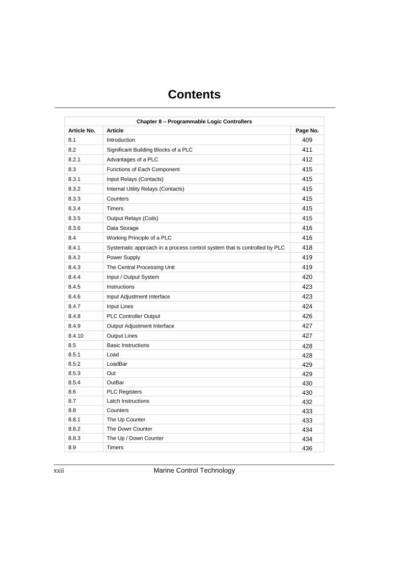
Chapter 8 – Programmable Logic Controllers
Article No. Article Page No.
8.1 Introduction 409
8.2 Significant Building Blocks of a PLC 411
8.2.1 Advantages of a PLC 412
8.3 Functions of Each Component 415
8.3.1 Input Relays (Contacts) 415
8.3.2 Internal Utility Relays (Contacts) 415
8.3.3 Counters 415
8.3.4 Timers 415
8.3.5 Output Relays (Coils) 415
8.3.6 Data Storage 416
8.4 Working Principle of a PLC 416
8.4.1 Systematic approach in a process control system that is controlled by PLC 418
8.4.2 Power Supply 419
8.4.3 The Central Processing Unit 419
8.4.4 Input / Output System 420
8.4.5 Instructions 423
8.4.6 Input Adjustment Interface 423
8.4.7 Input Lines 424
8.4.8 PLC Controller Output 426
8.4.9 Output Adjustment Interface 427
8.4.10 Output Lines 427
8.5 Basic Instructions 428
8.5.1 Load 428
8.5.2 LoadBar 429
8.5.3 Out 429
8.5.4 OutBar 430
8.6 PLC Registers 430
8.7 Latch Instructions 432
8.8 Counters 433
8.8.1 The Up Counter 433
8.8.2 The Down Counter 434
8.8.3 The Up / Down Counter 434
8.9 Timers 436

Contents
Marine Control Technology xxiii
Chapter 8 – Programmable Logic Controllers (Continued)
Article No. Article Page No.
8.9.1 On-delay Timer 436
8.9.2 Off-delay Timer 436
8.9.3 Retentive or Accumulating Timer 436
8.9.4 Timers at Work 437
8.10 Program Control 439
8.11 Control Relay Logic in the PLC 439
8.11.1 Interpreting and Constructing Ladder Diagrams 446
8.12 Level Application using a PLC 447
8.12.1 The Program Scan 449
8.12.2 Example of Operation of a Charge and Discharge Process using a PLC 450
Find the Answers 453
Chapter 9 – Final Control Elements
Article No. Article Page No.
9.1 Final Control Element 455
9.2 Valve Terms 456
9.2.1 Capacity 456
9.2.2 Range 456
9.2.3 Shut-off 456
9.2.4 Pressure Loss 456
9.2.5 Dead Band 456
9.2.6 Dynamic Response 456
9.2.7 Plugging 457
9.2.8 Balance 457
9.2.9 Accuracy 457
9.2.10 Flashing 457
9.2.11 Cavitation 457
9.2.12 Drift 457
9.2.13 Hysteresis 457
9.2.14 Linearity 457
9.2.15 Repeatability 457
9.2.16 Reproducibility 458
9.2.17 Response Time 458
9.2.18 Span 458
9.2.19 Gate Valve 458
9.2.20 Globe Valve 458
Contents
Marine Control Technology
xxiv
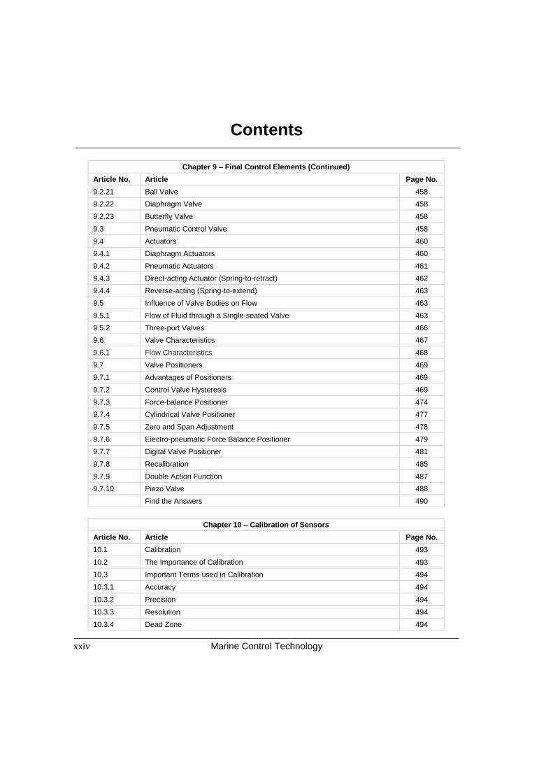
Chapter 9 – Final Control Elements (Continued)
Article No. Article Page No.
9.2.21 Ball Valve 458
9.2.22 Diaphragm Valve 458
9.2.23 Butterfly Valve 458
9.3 Pneumatic Control Valve 458
9.4 Actuators 460
9.4.1 Diaphragm Actuators 460
9.4.2 Pneumatic Actuators 461
9.4.3 Direct-acting Actuator (Spring-to-retract) 462
9.4.4 Reverse-acting (Spring-to-extend) 463
9.5 Influence of Valve Bodies on Flow 463
9.5.1 Flow of Fluid through a Single-seated Valve 463
9.5.2 Three-port Valves 466
9.6 Valve Characteristics 467
9.6.1 Flow Characteristics 468
9.7 Valve Positioners 469
9.7.1 Advantages of Positioners 469
9.7.2 Control Valve Hysteresis 469
9.7.3 Force-balance Positioner 474
9.7.4 Cylindrical Valve Positioner 477
9.7.5 Zero and Span Adjustment 478
9.7.6 Electro-pneumatic Force Balance Positioner 479
9.7.7 Digital Valve Positioner 481
9.7.8 Recalibration 485
9.7.9 Double Action Function 487
9.7.10 Piezo Valve 488
Find the Answers 490
Chapter 10 – Calibration of Sensors
Article No. Article Page No.
10.1 Calibration 493
10.2 The Importance of Calibration 493
10.3 Important Terms used in Calibration 494
10.3.1 Accuracy 494
10.3.2 Precision 494
10.3.3 Resolution 494
10.3.4 Dead Zone 494

Contents
Marine Control Technology xxv
Chapter 10 – Calibration of Sensors (Continued)
Article No. Article Page No.
10.3.5 Re-ranging 495
10.3.6 Bias / Offset Error 495
10.4 Calibration Under Controlled Conditions 495
10.5 Calibration Errors 497
10.5.1 Zero and Span Errors 498
10.6 Zero and Span Adjustments 500
10.7 Calibration Procedure for an Analog Linear Instrument 501
10.7.1 Up-tests and Down-tests 502
10.7.2 Step-wise Calibration 502
10.8 Calibration of an RTD 503
10.8.1 The Calibration Procedure 504
10.9 Calibration of a Thermocouple 505
10.9.1 The Loop Calibrator 506
10.10 Calibration of Pressure Transmitters 506
10.10.1 Calibration Procedure 508
10.10.2 Calibration of a Differential Pressure Transmitter 508
10.11 Calibration of an I/P Converter 509
10.11.1 Calibration Procedure 509
10.12 Calibration of a Smart Transmitter 510
10.12.1 Connecting a HART device in Parallel with a Loop 513
10.12.2 Re-ranging the Transmitter (Changing the LRV and URV) 514
10.12.3 Important Formula for Calibration Data Conversion 515
Find the Answers 516