Contents Switch-mode power supplies - …...Switch-mode power supplies – Overview AC / DC om 33 mm...
72
Contents Switch-mode power supplies Switch-mode power supplies Overview A.2 connectPower PROeco A.4 connectPower PRO-M A.12 connectPower PRO-H A.26 connectPower PRO-E A.40 connectPower INSTAPOWER A.56 connectPower WAVEPOWER A.64 connectPower DC/DC converter A.66 A Switch-mode power supplies A.1 1460790000 – 2014/2015
Transcript of Contents Switch-mode power supplies - …...Switch-mode power supplies – Overview AC / DC om 33 mm...

Contents
Switch-mode power supplies
Switch-mode power supplies Overview A.2
connectPower PROeco A.4
connectPower PRO-M A.12
connectPower PRO-H A.26
connectPower PRO-E A.40
connectPower INSTAPOWER A.56
connectPower WAVEPOWER A.64
connectPower DC/DC converter A.66
A
Switc
h-mod
e pow
er su
pplie
s
A.11460790000 – 2014/2015

Switch-mode power supplies – Overview
Switch-mode power supplies
The switch-mode power supplies feature a high degree of efficiency, compact dimensions and minimal heat generation.
They are an excellent, reliable solution for providing power in all automation applications – safely providing 24 V DC voltage.
The different product series are optimised for the automation industry: they feature Ex approvals for the processing industry, a flat shape perfect for distribution tasks within buildings, or provide decentralised control voltages.
All-purpose usage: with a wide range of AC/DC inputs, single-, double- or three-phase versions, and a wide temperature range. Additional performance increases are possible using simple parallel circuitry. Weidmüller
switch-mode power supplies can be depended upon for all applications because of their high efficiency and their resistance to both short circuits and overloads.
Weidmüller offers a system of one- and three-phase swtich-mode power supplies especially for the PRO-M family. These can be expanded with additional modules to create whole system solutions. The appropriate system can be assembled for any type of application: with redundancy circuits containing decoupled outputs, monitoring of the output voltage or triggering of circuit breakers.
A
Switc
h-mod
e pow
er su
pplie
s
A.2 1460790000 – 2014/2015
Switch-mode power supplies – Overview
AC / DC
from 33 mm
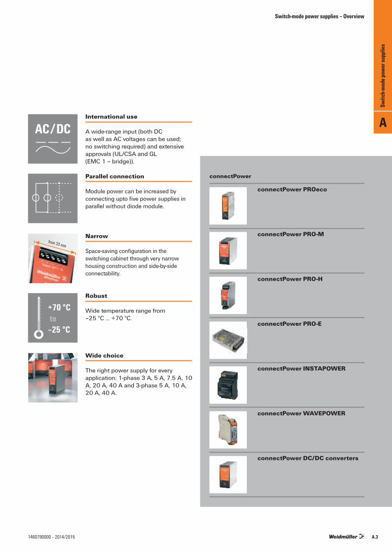
International use
A wide-range input (both DC as well as AC voltages can be used; no switching required) and extensive approvals (UL/CSA and GL (EMC 1 – bridge)).
Narrow
Space-saving configuration in the switching cabinet through very narrow housing construction and side-by-side connectability.
Parallel connection
Module power can be increased by connecting upto five power supplies in parallel without diode module.
Robust
Wide temperature range from –25 °C … +70 °C.
Wide choice
The right power supply for every application: 1-phase 3 A, 5 A, 7.5 A, 10 A, 20 A, 40 A and 3-phase 5 A, 10 A, 20 A, 40 A.
connectPower
connectPower PROeco
connectPower PRO-M
connectPower PRO-H
connectPower PRO-E
connectPower INSTAPOWER
connectPower WAVEPOWER
connectPower DC/DC converters
A
Switc
h-mod
e pow
er su
pplie
s
A.31460790000 – 2014/2015

connectPower PROeco
Derating curves Technical dataGeneral technical dataAmbient temp. operating / storage temperature –25 °C…+70 °C / –40 °C…+85 °CMax. perm. air humidity (operation) 5 %…95 % RHDegree of protection IP 20Class of protection I, with PE connectionPollution degree 2Insulation voltage input/output 3 kV E/A / 2 kV E/earth / 0.5 kV A/earthMTBF > 500.000 h acc. to IEC 1709 (SN29500)Parallel connection option yes, max. 5 without diode moduleHousing version metal, corrosion resistantMounting position, installation notice horizontal on mounting rail TS 35, 50 mm spacing
top and bottom for free air circulationShort-circuit protection Yes, automatic restartOverload protection Yes, IU characteristic curveOvertemperature protection Yes, automatic restartEMC / shock / vibrationNoise emission acc. to EN55022 Class BNoise immunity tests acc. to EN61000-4-2 (ESD), EN61000-4-3 and EN61000-4-8 (Fields),
EN61000-4-4 (Burst), EN61000-4-5 (Surge), EN61000-4-6 (conducted), EN61000-4-11 (Dips)
Limiting of mains voltage harmonic currents Acc. to EN61000-3-2Resistance against vibration and shock 1 g acc. to EN50178, shock: 15 g in all directionsElectrical safety (applied standards)Electrical equipment of machines Acc. to EN60204Safety transformers for switched-mode power units Acc. to EN61558-2-17Machinery with electronic equipment Acc. to EN50178 / VDE0160Safety extra-low voltage SELV acc. to EN60950-1, PELV acc. to EN60204-1Protective separation / protection against electrical shock VDE0100-410 / acc. to DIN57100-410Protection against dangerous shock currents Acc. to VDE0106-101
–25 0 20 30 40 50 60 70
120
100
80
60
40
20
0
Ambient temperature (°C)
≤ 480 Watt
I outp
ut (%
I N)
–25 0 20 30 40 50 60 70
120
100
80
60
40
20
0
Ambient temperature (°C)
960 Watt
I outp
ut (%
I N)
PROeco power supplies with basic functionality and a high level of reliability
• Single- and three-phase switched-mode power supply units• Slim design• Large temperature range from –25 °C to 70 °C• The output voltage can be precisely adjusted via the
potentiometer on the front• Remote monitoring via integrated status relay• Three-coloured LED indicators for simple error detection• Advanced visual warning at 90 % rated output current• International approvals
% \
A
Switc
h-mod
e pow
er su
pplie
s
A.4 1460790000 – 2014/2015

connectPower PROeco
Technical dataInputRated input voltageAC input voltage rangeAC frequency rangeDC input voltage rangeAC current consumptionDC current consumptionInput fuse (internal) / inrush currentRecommended back-up fuse
OutputRated output voltageOutput voltageRamp-up time / residual ripple, switching peaksRated output current @ Urated
Continuous output current @ 24 V DCPower boost @ 24 V DC, 60 °CCapacitive loadProtection against reverse voltages from the loadProtection against internal surge voltageSignallingDC OKAlarm ErrorVoltage monitoring / no-voltage contact / contact loadOn/Off relayGeneral dataEfficiencyPower loss @ idling / nominal loadEarth discharge currentPower factor (approx.)Mains buffering @ Irated
Parallel connection optionHeight x width x depth / weightApprovalsApprovalsConnection dataConductor connection systemNumber of terminalsWire cross-section, rigid min/max mm²Wire cross-section, flexible min/max mm²Wire cross-section, AWG/kcmil min/maxMin./max. tightening torque range NmStripping length mmNote
Ordering data
Note
100 … 240 V AC85 … 264 V AC (Derating @ 100 V AC)47 … 63 Hz80 … 370 DC (Derating @ 120 V DC)0.55 A @ 230 V AC / 1.04 A @ 110 V AC0.22 A @ 370 V DC / 0.68 A @ 120 V DCYes / max. 402 A / DI, Safety fuse 6 A, Char. B, Circuit breaker 2...4 A, Char. C, Circuit breaker
24 V DC ± 1 % 22...28 V DC (adjustable via potentiometer on front)< 100 ms / < 50 mVSS @ 24 V DC, IR3 A up to 55 °C3 A @ 55 °C, 2.25 A @ 70 °C3.6 A for 1 min, ED = 5 %Unrestricted30…35 V DC35 V DC
LED Green (Uoutput > 21.6 V DC)LED Yellow (Ioutput > 90 % IR )LED Red (Overload, overtemperature, short-circuit, Uoutput < 20.4 V DC)Yes / NO contact / max. 30 V AC/DC 1 AOutput voltage > 21.6 V DC / < 20.4 V DC
> 87 % @ 230 V AC & 3 A4 W / 9.5 W< 1 mA> 0.42 @ 230 V AC / > 0.45 @ 115 V AC> 100 ms @ 230 V AC / > 20 ms @ 115 V ACyes, max. 5125 / 34 / 100 mm / 0.5 kg
CE, TÜV (EN/IEC 60950-1), cULus (Pending) Input OutputScrew connection Screw connection3 for L/N/PE 5 (13,14,+, - -)0.5/6 0.5/60.5/2.5 0.5/2.526/12 26/120.5/0.6 0.5/0.66 6
Type Qty. Order No.PRO ECO 72W 24V 3A 1 1469470000The internal varistor found in a switch-mode power unit does not replace the necessary surge protection in a system.
100 … 240 V AC85 … 264 V AC (Derating @ 100 V AC)47 … 63 Hz80 … 370 DC (Derating @ 120 V DC)1.26 A @ 230 V AC / 2.24 A @ 110 V AC0.39 A @ 370 V DC / 1.16 A @ 120 V DCYes / max. 404 A / DI, Safety fuse 6 A, Char. B, Circuit breaker 3...5 A, Char. C, Circuit breaker
24 V DC ± 1 % 22...28 V DC (adjustable via potentiometer on front)< 100 ms / < 50 mVSS @ 24 V DC, IR5 A up to 55 °C5 A @ 55 °C, 3.75 A @ 70 °C6 A for 1 min, ED = 5 %Unrestricted30…35 V DC35 V DC
LED Green (Uoutput > 21.6 V DC)LED Yellow (Ioutput > 90 % IR )LED Red (Overload, overtemperature, short-circuit, Uoutput < 20.4 V DC)Yes / NO contact / max. 30 V AC/DC 1 AOutput voltage > 21.6 V DC / < 20.4 V DC
> 87 % @ 230 V AC & 5 A4 W / 15 W< 1 mA> 0.47 @ 230 V AC / > 0.56 @ 115 V AC> 80 ms @ 230 V AC / > 20 ms @ 115 V ACyes, max. 5125 / 40 / 100 mm / 0.6 kg
CE, TÜV (EN/IEC 60950-1), cULus (Pending) Input OutputScrew connection Screw connection3 for L/N/PE 6 (13,14,+,+, - -)0.5/6 0.5/6 0.5/2.5 0.5/2.526/12 26/120.5/0.6 0.5/0.66 6
Type Qty. Order No.PRO ECO 120W 24V 5A 1 1469480000The internal varistor found in a switch-mode power unit does not replace the necessary surge protection in a system.
PROeco PRO ECO 72W 24V 3A
+
––
1314
L (+)
N (–)
PE DCAC
Pay attention to polarity of DC connection
PRO ECO 120W 24V 5A
++––
1314
L (+)
N (–)
PE DCAC
Pay attention to polarity of DC connection
A
Switc
h-mod
e pow
er su
pplie
s
A.51460790000 – 2014/2015

Technical dataInputRated input voltageAC input voltage rangeAC frequency rangeDC input voltage rangeAC current consumptionDC current consumptionInput fuse (internal) / inrush currentRecommended back-up fuse
OutputRated output voltageOutput voltageRamp-up time / residual ripple, switching peaksRated output current @ Urated
Continuous output current @ 24 V DCPower boost @ 24 V DC, 60 °CCapacitive loadProtection against reverse voltages from the load Protection against internal surge voltageSignallingDC OKAlarm ErrorVoltage monitoring / no-voltage contact / contact loadOn/Off relayGeneral dataEfficiencyPower loss @ idling / nominal loadEarth discharge currentPower factor (approx.)Mains buffering @ Irated
Parallel connection optionHeight x width x depth / weightApprovalsApprovalsConnection dataConductor connection systemNumber of terminalsWire cross-section, rigid min/max mm²Wire cross-section, flexible min/max mm²Wire cross-section, AWG/kcmil min/maxMin./max. tightening torque range NmStripping length mmNote
Ordering data
Note
100 … 240 V AC85 … 264 V AC (Derating @ 100 V AC)47 … 63 Hz80 … 370 DC (Derating @ 120 V DC)1.23 A @ 230 V AC / 2.47 A @ 110 V AC1.18 A @ 370 V DC / 2.4 A @ 120 V DCYes / max. 15 A4 A / DI, Safety fuse 10 A, Char. B, Circuit breaker 3...4 A, Char. C, Circuit breaker
24 V DC ± 1 % 22...28 V DC (adjustable via potentiometer on front)< 100 ms / < 50 mVSS @ 24 V DC, IR10 A up to 55 °C10 A @ 55 °C, 7.5 A @ 70 °C12 A for 1 min, ED = 5 %Unrestricted30…35 V DC35 V DC
LED Green (Uoutput > 21.6 V DC)LED Yellow (Ioutput > 90 % IR )LED Red (Overload, overtemperature, short-circuit, Uoutput < 20.4 V DC)Yes / NO contact / max. 30 V AC/DC 1 AOutput voltage > 21.6 V DC / < 20.4 V DC
> 90 % @ 230 V AC & 10 A3 W / 24 W< 1 mA> 0.93 @ 230 V AC / > 0.99 @ 115 V AC> 20 ms @ 230 V AC / > 20 ms @ 115 V ACyes, max. 5125 / 60 / 100 mm / 1 kg
CE, TÜV (EN/IEC 60950-1), cULus (Pending) Input OutputScrew connection Screw connection3 for L/N/PE 6 (13,14,+,+, - -)0.5/6 0.5/60.5/2.5 0.5/2.526/12 26/120.5/0.6 0.5/0..66 6
Type Qty. Order No.PRO ECO 240W 24V 10A 1 1469490000The internal varistor found in a switch-mode power unit does not replace the necessary surge protection in a system.
100 … 240 V AC85 … 264 V AC (Derating @ 100 V AC)47 … 63 Hz80 … 370 DC (Derating @ 120 V DC)2.37 A @ 230 V AC / 5.2 A @ 110 V AC1.55 A @ 370 V DC / 4.65 A @ 120 V DCYes / max. 3 A6 A / DI, Safety fuse 16 A, Char. B, Circuit breaker 6…8 A, Char. C, Circuit breaker
24 V DC ± 1 % 22...28 V DC (adjustable via potentiometer on front)< 100 ms / < 50 mVSS @ 24 V DC, IR20 A up to 55 °C20 A @ 55 °C, 15 A @ 70 °C24 A for 1 min, ED = 5 %Unrestricted30…35 V DC35 V DC
LED Green (Uoutput > 21.6 V DC)LED Yellow (Ioutput > 90 % IR )LED Red (Overload, overtemperature, short-circuit, Uoutput < 20.4 V DC)Yes / NO contact / max. 30 V AC/DC 1 AOutput voltage > 21.6 V DC / < 20.4 V DC
> 91 % @ 230 V AC & 20 A5 W / 43 W< 1 mA> 0.97 @ 230 V AC / > 0.99 @ 115 V AC> 20 ms @ 230 V AC / > 20 ms @ 115 V ACyes, max. 3125 / 100 / 120 mm / 1.6 kg
CE, TÜV (EN/IEC 60950-1), cULus (Pending) Input OutputScrew connection Screw connection3 for L/N/PE 7 (13,14,+,+, - ,-,-)0.5/6 0.18/60.5/2.5 0.5/2.526/12 26/100.5/0.6 0.5/0.66 7
Type Qty. Order No.PRO ECO 480W 24V 20A 1 1469510000The internal varistor found in a switch-mode power unit does not replace the necessary surge protection in a system.
PROeco PRO ECO 240W 24V 10A
++––
1314
L (+)
N (–)
PE DCAC
Pay attention to polarity of DC connection
PRO ECO 480W 24V 20A
++–––
1314
L (+)
N (–)
PE DCAC
Pay attention to polarity of DC connection
connectPower PROeco
A
Switc
h-mod
e pow
er su
pplie
s
A.6 1460790000 – 2014/2015

Technical dataInputRated input voltageAC input voltage rangeAC frequency rangeDC input voltage rangeAC current consumptionDC current consumptionInput fuse (internal) / inrush currentRecommended back-up fuse
OutputRated output voltageOutput voltageRamp-up time / residual ripple, switching peaksRated output current @ Urated
Continuous output current @ 24 V DCPower boost @ 24 V DC, 60 °CCapacitive loadProtection against reverse voltages from the load Protection against internal surge voltageSignallingDC OKAlarm ErrorVoltage monitoring / no-voltage contact / contact loadOn/Off relayGeneral dataEfficiencyPower loss @ idling / nominal loadEarth discharge currentPower factor (approx.)Mains buffering @ Irated
Parallel connection optionHeight x width x depth / weightApprovalsApprovalsConnection dataConductor connection systemNumber of terminalsWire cross-section, rigid min/max mm²Wire cross-section, flexible min/max mm²Wire cross-section, AWG/kcmil min/maxMin./max. tightening torque range NmStripping length mmNote
Ordering data
Note
100 … 240 V AC85 … 264 V AC (Derating @ 100 V AC)47 … 63 Hz80 … 370 DC (Derating @ 120 V DC)4.6 A @ 230 V AC / 9.9 A @ 110 V AC2.9 A @ 370 V DC / 9 A @ 120 V DCYes / max. 3 A16 A / DI, Safety fuse 20 A, Char. B, Circuit breaker 16 A, Char. C, Circuit breaker
24 V DC ± 1 % 22...28 V DC (adjustable via potentiometer on front)< 100 ms / < 50 mVSS @ 24 V DC, IR40 A up to 50 °C40 A @ 50 °C, 24 A @ 70 °C48 A for 1 min, ED = 5 %Unrestricted30…35 V DC35 V DC
LED Green (Uoutput > 21.6 V DC)LED Yellow (Ioutput > 90 % IR )LED Red (Overload, overtemperature, short-circuit, Uoutput < 20.4 V DC)Yes / NO contact / max. 30 V AC/DC 1 AOutput voltage > 21.6 V DC / < 20.4 V DC
> 93 % @ 230 V AC & 40 A6 W / 76 W< 1 mA> 0.97 @ 230 V AC / > 0.99 @ 115 V AC> 20 ms @ 230 V AC / > 20 ms @ 115 V ACyes, max. 3125 / 160 / 120 mm / 2.9 kg
CE, TÜV (EN/IEC 60950-1), cULus (Pending) Input OutputScrew connection Screw connection3 for L/N/PE 7 (13,14,+,+,+, - -)0.18/6 0.5/160.5/2.5 2.5/1026/10 22/80.5/0.6 1.2/1.57 12
Type Qty. Order No.PRO ECO 960W 24V 40A 1 1469520000The internal varistor found in a switch-mode power unit does not replace the necessary surge protection in a system.
PROeco PRO ECO 960W 24V 40A
++–––
1314
L (+)
N (–)
PE DCAC
Pay attention to polarity of DC connection
connectPower PROeco
A
Switc
h-mod
e pow
er su
pplie
s
A.71460790000 – 2014/2015

Technical dataInputRated input voltageAC input voltage rangeAC frequency rangeDC input voltage rangeAC current consumptionDC current consumptionInput fuse (internal) / inrush current
Recommended back-up fuse
OutputRated output voltageOutput voltageRamp-up time / residual ripple, switching peaksRated output current @ Urated
Continuous output current @ 24 V DCPower boost @ 24 V DC, 60 °CCapacitive loadProtection against reverse voltages from the load Protection against internal surge voltageSignallingDC OKAlarm ErrorVoltage monitoring / no-voltage contact / contact loadOn/Off relayGeneral dataEfficiencyPower loss @ idling / nominal loadEarth discharge currentPower factor (approx.)Mains buffering @ Irated
Parallel connection optionHeight x width x depth / weightApprovalsApprovalsConnection dataConductor connection systemNumber of terminalsWire cross-section, rigid min/max mm²Wire cross-section, flexible min/max mm²Wire cross-section, AWG/kcmil min/maxMin./max. tightening torque range NmStripping length mmNote
Ordering data
Note
3 x 400...3 x 500 V AC (Wide-range input)3 x 340...3 x 575 V AC / 2 x 360...2 x 575 V AC47...63 Hz450...800 V DC (max. 500 V DC in accordance with UL 508)0.6 A @ 3 x 500 V AC / 0.8 A @ 3 x 400 V AC0.4 A @ 800 V DC / 0.7 A @ 450 V DCYes / max. 50 A2 A / DI, Safety fuse 2...3 A, Char. C, Circuit breaker
24 V DC ± 1 % 22...28 V DC (adjustable via potentiometer on front)< 100 ms / < 50 mVSS @ 24 V DC, IR10 A up to 55 °C10 A @ 55 °C, 7.5 A @ 70 °C12 A for 1 min, ED = 5 %Unrestricted30…35 V DC35 V DC
LED Green (Uoutput > 21.6 V DC)LED Yellow (Ioutput > 90 % IR )LED Red (Overload, overtemperature, short-circuit, Uoutput < 20.4 V DC)Yes / NO contact / max. 30 V AC/DC 1 AOutput voltage > 21.6 V DC / < 20.4 V DC
88 % @ 3 x 500 V AC / 89 % @ 3 x 400 V AC8 W / 26 W< 0.5 mA> 0.45 @ 3 x 500 V AC / > 0.5 @ 3 x 400 V AC> 40 ms @ 3 x 500 V AC / > 20 ms @ 3 x 400 V ACyes, max. 5125 / 60 / 100 mm / 1 kg
CE, TÜV (EN/IEC 60950-1), cULus (Pending) Input OutputScrew connection Screw connection4 for L1/L2/L3/PE 6 (13,14,+,+, - -)0.18/6 0.5/60.5/2.5 0.5/2.526/10 26/120.5/0.6 0.5/0.67 6
Type Qty. Order No.PRO ECO3 240W 24V 10A 1 1469540000The internal varistor found in a switch-mode power unit does not replace the necessary surge protection in a system.
PROeco PRO ECO3 240W 24V 10A
++––
1314
DCAC
Pay attention to polarity of DC connection
L1 (+)
L2 (–)
L3
PE
connectPower PROeco
3 x 400...3 x 500 V AC (Wide-range input)3 x 340...3 x 575 V AC / 2 x 360...2 x 575 V AC47...63 Hz450...800 V DC (max. 500 V DC in accordance with UL 508)0.3 A @ 3 x 500 V AC / 0.4 A @ 3 x 400 V AC0.2 A @ 800 V DC / 0.4 A @ 450 V DCYes / max. 40 A2 A / DI, Safety fuse 2...3 A, Char. C, Circuit breaker
24 V DC ± 1 % 22...28 V DC (adjustable via potentiometer on front)< 100 ms / < 50 mVSS @ 24 V DC, IR5 A up to 55 °C5 A @ 55 °C, 3.75 A @ 70 °C6 A for 1 min, ED = 5 %Unrestricted30…35 V DC35 V DC
LED Green (Uoutput > 21.6 V DC)LED Yellow (Ioutput > 90 % IR )LED Red (Overload, overtemperature, short-circuit, Uoutput < 20.4 V DC)Yes / NO contact / max. 30 V AC/DC 1 AOutput voltage > 21.6 V DC / < 20.4 V DC
87 % @ 3 x 500 V AC / 88 % @ 3 x 400 V AC6 W / 13 W< 1 mA> 0.4 @ 3 x 500 V AC / > 0.45 @ 3 x 400 V AC> 40 ms @ 3 x 500 V AC / > 20 ms @ 3 x 400 V ACyes, max. 5125 / 40 / 100 mm / 0.6 kg
CE, TÜV (EN/IEC 60950-1), cULus (Pending) Input OutputScrew connection Screw connection4 for L1/L2/L3/PE 6 (13,14,+,+, - -)0.18/6 0.5/60.5/2.5 0.5/2.526/10 26/120.5/0.6 0.5/0.68 6
Type Qty. Order No.PRO ECO3 120W 24V 5A 1 1469530000The internal varistor found in a switch-mode power unit does not replace the necessary surge protection in a system.
PRO ECO3 120W 24V 5A
++––
1314
DCAC
Pay attention to polarity of DC connection
L1 (+)
L2 (–)
L3
PE
A
Switc
h-mod
e pow
er su
pplie
s
A.8 1460790000 – 2014/2015

Technical dataInputRated input voltageAC input voltage rangeAC frequency rangeDC input voltage rangeAC current consumptionDC current consumptionInput fuse (internal) / inrush currentRecommended back-up fuse
OutputRated output voltageOutput voltageRamp-up time / residual ripple, switching peaksRated output current @ Urated
Continuous output current @ 24 V DCPower boost @ 24 V DC, 60 °CCapacitive loadProtection against reverse voltages from the load Protection against internal surge voltageSignallingDC OKAlarm ErrorVoltage monitoring / no-voltage contact / contact loadOn/Off relayGeneral dataEfficiencyPower loss @ idling / nominal loadEarth discharge currentPower factor (approx.)Mains buffering @ Irated
Parallel connection optionHeight x width x depth / weightApprovalsApprovalsConnection dataConductor connection systemNumber of terminalsWire cross-section, rigid min/max mm²Wire cross-section, flexible min/max mm²Wire cross-section, AWG/kcmil min/maxMin./max. tightening torque range NmStripping length mmNote
Ordering data
Note
3 x 400...3 x 500 V AC (Wide-range input)3 x 340...3 x 575 V AC / 2 x 360...2 x 575 V AC47...63 Hz450...800 V DC (max. 500 V DC in accordance with UL 508)2.15 A @ 3 x 500 V AC / 2.68 A @ 3 x 400 V AC1.37 A @ 800 V DC / 2.37 A @ 450 V DCYes / max. 40 A6 A / DI, Safety fuse 10 A, Char. B, Circuit breaker 6...8 A, Char. C, Circuit breaker
24 V DC ± 1 % 22...28 V DC (adjustable via potentiometer on front)< 100 ms / < 50 mVSS @ 24 V DC, IR40 A up to 50 °C40 A @ 50 °C, 24 A @ 70 °C48 A for 1 min, ED = 5 %Unrestricted30…35 V DC35 V DC
LED Green (Uoutput > 21.6 V DC)LED Yellow (Ioutput > 90 % IR )LED Red (Overload, overtemperature, short-circuit, Uoutput < 20.4 V DC)Yes / NO contact / max. 30 V AC/DC 1 AOutput voltage > 21.6 V DC / < 20.4 V DC
90 % @ 3 x 500 V AC / 91 % @ 3 x 400 V AC5 W / 95 W< 1 mA> 0.56 @ 3 x 500 V AC / > 0.56 @ 3 x 400 V AC> 25 ms @ 3 x 500 V AC / > 20 ms @ 3 x 400 V ACyes, max. 3125 / 160 / 120 mm / 2.5 kg
CE, TÜV (EN/IEC 60950-1), cULus (Pending) Input OutputScrew connection Screw connection4 for L1/L2/L3/PE 7 (13,14,+,+, - ,-,-)0.18/6 0.5/160.5/2.5 2.5/1026/10 22/80.5/0.6 1.2/1.57 12
Type Qty. Order No.PRO ECO3 960W 24V 40A 1 1469560000The internal varistor found in a switch-mode power unit does not replace the necessary surge protection in a system.
PROeco PRO ECO3 960W 24V 40A
++–––
1314
DCAC
Pay attention to polarity of DC connection
L1 (+)
L2 (–)
L3
PE
3 x 400...3 x 500 V AC (Wide-range input)3 x 340...3 x 575 V AC / 2 x 360...2 x 575 V AC47...63 Hz450...800 V DC (max. 500 V DC in accordance with UL 508)1.2 A @ 3 x 500 V AC / 1.5 A @ 3 x 400 V AC0.7 A @ 800 V DC / 1.2 A @ 450 V DCYes / max. 50 A4 A / DI, Safety fuse 3...5 A, Char. C, Circuit breaker
24 V DC ± 1 % 22...28 V DC (adjustable via potentiometer on front)< 100 ms / < 50 mVSS @ 24 V DC, IR20 A up to 55 °C20 A @ 55 °C, 15 A @ 70 °C24 A for 1 min, ED = 5 %Unrestricted30…35 V DC35 V DC
LED Green (Uoutput > 21.6 V DC)LED Yellow (Ioutput > 90 % IR )LED Red (Overload, overtemperature, short-circuit, Uoutput < 20.4 V DC)Yes / NO contact / max. 30 V AC/DC 1 AOutput voltage > 21.6 V DC / < 20.4 V DC
89 % @ 3 x 500 V AC / 90 % @ 3 x 400 V AC8 W / 48 W< 0.5 mA> 0.41 @ 3 x 500 V AC / > 0.43 @ 3 x 400 V AC> 30 ms @ 3 x 500 V AC / > 20 ms @ 3 x 400 V ACyes, max. 3125 / 100 / 120 mm / 1.3 kg
CE, TÜV (EN/IEC 60950-1), cULus (Pending) Input OutputScrew connection Screw connection4 for L1/L2/L3/PE 7 (13,14,+,+, - ,-,-)0.18/6 0.18/60.5/2.5 0.5/2.526/10 26/100.5/0.6 0.5/0.67 7
Type Qty. Order No.PRO ECO3 480W 24V 20A 1 1469550000The internal varistor found in a switch-mode power unit does not replace the necessary surge protection in a system.
PRO ECO3 480W 24V 20A
++–––
1314
DCAC
Pay attention to polarity of DC connection
L1 (+)
L2 (–)
L3
PE
connectPower PROeco
A
Switc
h-mod
e pow
er su
pplie
s
A.91460790000 – 2014/2015

A
A.10 1460790000 – 2014/2015
connectPower PROeco diode module
DC DCE1E2–V–V
+
–
+V –V
–VE2E1
Technical dataInputInput voltageInput currentOutputOutput voltageOutput currentGeneral dataAmbient temperature (operational)Storage temperatureDegree of efficiency at max. loadMounting position, installation noticeInstallation adviceWeightApprovals
DimensionsClamping range (nominal / min. / max.) mm²Depth x width x height mmNote
Ordering data
Screw connection
Note
AccessoriesNote
CP DM 10
+V -V
E1 E2 -V
40 V DC max. 2 x 0...10 A max.
Uin - 0.5 V typical 0...20 A max. or 10 A max. for redundancy operation
-10 °C...+55 °C-20 °C...+85 °C95.5%horizontally, on terminal rail TS 35Space: side ≥ 2 cm; above/below ≥ 10 cm0.4 kgCE; cULus; cURus
Input Output4 / 0.13 / 6 4 / 0.13 / 6110 / 55.5 / 125 110 / 55.5 / 125
Type Qty. Order No.CP DM 10 1 8710620000
CP DM 20
+V -V
E1 E2 -V
40 V DC max. 2 x 0...20 A max.
Uin - 0.5 V typical 0...40 A max. or 20 A max. for redundant operations
-10 °C...+55 °C-20 °C...+85 °C97.5%horizontally, on terminal rail TS 35Space: side ≥ 2 cm; above/below ≥ 10 cm0.4 kgCE; cULus; cURus
Input Output4 / 0.13 / 6 10 / 0.32 / 16110 / 55.5 / 125 110 / 55.5 / 125
Type Qty. Order No.CP DM 20 1 8768650000
Switc
h-mod
e pow
er su
pplie
sconnectPower PROeco

Small metal foot
Type Order No.MTA 30 MF 1251320000
Small wall mounting
Type Order No.CP A WALLADAPTER 30 MM 1461870000
Markers
Type Colour Qty. Order No.SM 18/9.5 K MC NE WS white 200 1248580000
End bracketFor DIN rail TS 35
Polyamide with fibre glass, screwable Colour Torque Qty. Order No.WEW 35/1 SW black 1.2 Nm 50 1162600000
Large metal foot
Type Order No.MTA 45 MF 1251310000
Large wall mounting
Type Order No.CP A WALLADAPTER 45 MM 1461850000
Small plastic foot
Type Order No.MTA 30 BK 1168970000
Large plastic foot
Type Order No.MTA 45 BK 1962250000
Small screwdriver
Type Blade type Size/AF a b c Order No.SDIK PH1 1.00 80 9008570000SDIS 0.5X3.0X100 B 0.5 3 100 9008380000
PROeco - Accessories
A
Switc
h-mod
e pow
er su
pplie
s
A.111460790000 – 2014/2015

connectPowerPRO-M
Technical dataGeneral technical dataCurrent limiting > 120 % IRAmbient temp. operating / storage temperature –25 °C…+70 °C / –40 °C… +85 °CMax. perm. air humidity (operation) 5 %…95 % RHDegree of protection IP 20Class of protection I, with PE connectionPollution degree 2Insulation voltage input/output 3 kV E/A / 2 kV E/earth / 0.5 kV A/earthMTBF > 500,000 h acc. to IEC 1709 (SN29500)Protection against reverse voltages from the load 30…35 V DCParallel connection option yes, without diode moduleHousing version metal, corrosion resistantIndication operation, green LEDMounting position, installation notice horizontal on mounting rail TS35, 50 mm spacing top and bottom for free
air circulation, can be mounted side by side with no space in betweenEMC / shock / vibrationNoise emission acc. to EN55022 Class BNoise immunity tests acc. to EN61000-4-2 (ESD), EN61000-4-3 and EN61000-4-8 (Fields),
EN61000-4-4 (Burst), EN61000-4-5 (Surge), EN610004-6 (conducted), EN61000-4-11 (Dips)
Limiting of mains voltage harmonic currents Acc. to EN61000-3-2Resistance against vibration and shock Acc. to EN50178, shock: 30 g in all directionsVibration resistance 1g acc. to EN60068-2-6Electrical safety (applied standards)Electrical equipment of machines Acc. to EN60204Safety transformers for switched-mode power units Acc. to EN61558-2-16Machinery with electronic equipment Acc. to EN50178 / VDE0160Safety extra-low voltage SELV acc. to EN60950, PELV acc. to EN60204Protective separation / protection against electrical shock VDE0100-410 / acc. to DIN57100-410Protection against dangerous shock currents Acc. to VDE0106-101
+
–
L (+)
N (–)
PE DCAC
L1 (+)L2 (–) L3 PE
+
–DCAC
Project-planning dataType 24 V / 3 A 24 V / 5 A 24 V / 7.5 A 24 V / 10 A 24 V / 20 A 24 V / 40 A 24 V / 5 A 24 V / 10 A 24 V / 20 A 24 V / 40 A
1 - phase 3 - phaseRated input voltage 100...240 V AC 3 x 400...500 V ACMains voltage range 85...264 V AC 3 x 320...575 V ACMains input current 1.3...0.6 A 2.1...0.9 A 2.1...0.9 A 2.8...1.2 A 5.6...2.4 A 11.1...4.7 A 0.3...0.28 A 0.55...0.5 A 1.0...0.9 A 2.5...2.0 ARec. fuse [char.] 2 A / D I / II 4 A / D I / II 6 A / D I / II 6 A / D I / II 10 A / D I / II 16 A / D I / II 2 A / D I / II 2 A / D I / II 2 A / D I / II 4 A / D I / II
6 A, [B] 6 A, [B] 10 A, [B] 10 A, [B] 20 A, [B] 25 A, [B] - - - 10 A, [B] 2...4 A, [C] 3...5 A, [C] 5...10 A, [C] 5...10 A, [C] 10...12 A, [C] 14...16 A, [C] 1...2 A, [C] 2...3 A, [C] 3...5 A, [C] 6...8 A, [C]
Efficiency @ 230 V AC, @ 3x400 V AC 90 % 90 % 91 % 90 % 90 % 91 % 90 % 90 % 90 % 91 %Rated power loss [W] 8 W 13 W 18 W 27 W 53 W 95 W 13 W 27 W 53 W 95 WInstallation width mm 33 40 50 60 121 180 40 60 121 180
Input terminals Screw connectionMin./max. tightening torque Nm 0.5...0.6 0.5...0.6 0.5...0.6 0.5...0.6 0.5...0.6Conductor, solid min/max mm2 0.5...6 0.5...6 0.08...4 0.5...6 0.5...6Conductor, flexible min/max mm2 0.5...2.5 0.5...2.5 0.5...2.5 0.5...2.5 0.5...2.5Conductor, AWG/kcmil min/max 26 / 12 26 / 10 28 / 12 26 / 12 26 / 12
Output terminals Screw connectionNumber plus/minus 2 / 2 2 / 3Min./max. tightening torque Nm 0.5...0.6 0.5...0.6 0.5...0.6 0.5...0.6 0.5...0.6 0.5...0.6Conductor, solid min/max mm2 0.5...6 0.5...6 0.5...16 0.5...6 0.5...6 0.5...16Conductor, flexible min/max mm2 0.5...2.5 0.5...2.5 2.5...10 0.5...2.5 0.5...2.5 2.5...10Conductor, AWG/kcmil min/max 26 / 12 26 / 10 22 / 6 26 / 12 26 / 10 22 / 6
connectPower PRO-M
% { \ u "
Pay attention to polarity of DC connection
Two-Phase operation also possible
Max. limiting average on state current [A]Type\Temp. 45°C 50°C 55°C 60°C 65°C 70°C1ph 24V / 3A 3.6 3.4 3.2 3 2.6 2.31ph 24V / 5A 6 5.7 5.3 5 4.4 3.81ph 24V / 7.5A 9 8.5 8 7.5 6.6 5.61ph 24V / 10A 12 11.3 10.7 10 8.8 7.51ph 24V / 20A 24 22.7 21.3 20 17.5 151ph 24V / 40A 48 45.3 42.7 40 35 303ph 24V / 5A 6 5.7 5.3 5 4.4 3.83ph 24V / 10A 12 11.3 10.7 10 8.8 7.53ph 24V / 20A 24 22.7 21.3 20 17.5 153ph 24V / 40A 48 45.3 42.7 40 35 30
+
–
L (+)
N (–)
PE DCAC
L1 (+)L2 (–) L3 PE
+
–DCAC
A
Switc
h-mod
e pow
er su
pplie
s
A.12 1460790000 – 2014/2015

A
A.131460790000 – 2014/2015
connectPower PRO-M
Technical dataInputRated input voltageInput voltage range ACFrequency range ACDC input voltage rangeAC current consumptionDC current consumptionInput fuse (internal) / Inrush currentRecommended back-up fuse
OutputRated output voltageOutput voltageResidual ripple, breaking spikesRated (nominal) output current @ UNom
Continous output current @ 24 V DCPowerboost @ 24 V DC, 60 °CGeneral dataDegree of efficiencyPower factor (approx.)AC failure bridging time @ INom
Parallel connection optionDepth x width x heightWeightApprovalsApprovals
Connection dataWire connection methodNumber of terminalsWire cross-section, rigid min/max mm²Wire cross-section, flexible min/max mm²Wire cross-section, AWG/kcmil min/maxNote
Ordering data
Plastic clip-on footMetal clip-on foot
Note
AccessoriesNote
CP M SNT 70W 24V 3A
100...240 V AC (wide-range input) 85…264 V AC (Derating @ 100 V AC) 47...63 Hz 80…370 V DC (Derating @ 120 V DC) 0.6 A @ 230 V AC / 1.1 A @ 115 V AC 0.25 A @ 370 V DC / 0.7 A @ 120 V DCYes / max. 40 A2 A / DI, fuse 6 A, Char. B, circuit breaker 2...4 A, Char. C, circuit breaker
24 V DC ± 1 % 22.5...29.5 V DC (adjustable via potentiometer on front) < 50 mVSS @ 24 V DC, IN3 A @ 60 °C 3.6 A @ 45 °C, 3.2 A @ 55 °C, 2.3 A @ 70 °C 3.6 A for 1 min, ED = 5 %
90 % @ 230 V AC / 88 % @ 115 V AC > 0.6 @ 230 V AC / > 0,65 @ 115 V AC > 20 ms @ 230 V AC / > 20 ms @ 115 V ACyes, max. 5125 / 33 / 130 mm0.57 kg
CE; cULus; cURus; GL; GOSTME25; TUEV
Input OutputScrew connection Screw connection3 for L/N/PE 4 (++ / --)0.5 / 6 0.5 / 60.5 / 2.5 0.5 / 2.526 / 12 26 / 12*) Recommendation applies only to AC operation; the max. permissibleoperating voltage is to be observed in all cases!
Type Qty. Order No.CP M SNT 70W 24V 3A 1 8951330000CP M SNT 70W 24V 3A 1 8951330010
The internal varistor found in a switch-mode power supply does not replace the necessary surge protection in a system.
CP M SNT 120W 24V 5A
100...240 V AC (wide-range input) 85…264 V AC (Derating @ 100 V AC) 47...63 Hz 80…370 V DC (Derating @ 120 V DC) 1.1 A @ 230 V AC / 2.0 A @ 115 V AC 0.4 A @ 370 V DC / 1.2 A @ 120 V DCYes / max. 40 A4 A / DI, fuse 6 A, Char. B, circuit breaker 3...5 A, Char. C, circuit breaker
24 V DC ± 1 % 22.5...29.5 V DC (adjustable via potentiometer on front) < 50 mVSS @ 24 V DC, IN5 A @ 60 °C 6.0 A @ 45 °C, 5.3 A @ 55 °C, 3.8 A @ 70 °C 6 A for 1 min, ED = 5 %
90 % @ 230 V AC / 88 % @ 115 V AC > 0.5 @ 230 V AC / > 0.6 @ 115 V AC > 100 ms @ 230 V AC / > 20 ms @ 115 V ACyes, max. 5125 / 40 / 130 mm0.7 kg
CE; cULus; cURus; GL; GOSTME25; TUEV
Input OutputScrew connection Screw connection3 for L/N/PE 5 (++ / ---)0.5 / 6 0.5 / 60.5 / 2.5 0.5 / 2.526 / 12 26 / 12*) Recommendation applies only to AC operation; the max. permissibleoperating voltage is to be observed in all cases!
Type Qty. Order No.CP M SNT 120W 24V 5A 1 8951340000CP M SNT 120W 24V 5A 1 8951340010
The internal varistor found in a switch-mode power supply does not replace the necessary surge protection in a system.
Switc
h-mod
e pow
er su
pplie
s
connectPower PRO-M

A
A.14 1460790000 – 2014/2015
connectPower PRO-M
Technical dataInputRated input voltageInput voltage range ACFrequency range ACDC input voltage rangeAC current consumptionDC current consumptionInput fuse (internal) / Inrush currentRecommended back-up fuse
OutputRated output voltageOutput voltageResidual ripple, breaking spikesRated (nominal) output current @ UNom
Continous output current @ 24 V DCPowerboost @ 24 V DC, 60 °CGeneral dataDegree of efficiencyPower factor (approx.)AC failure bridging time @ INom
Parallel connection optionDepth x width x heightWeightApprovalsApprovals
Connection dataWire connection methodNumber of terminalsWire cross-section, rigid min/max mm²Wire cross-section, flexible min/max mm²Wire cross-section, AWG/kcmil min/maxNote
Ordering data
Plastic clip-on footMetal clip-on foot
Note
AccessoriesNote
CP M SNT 180W 24V 7.5A
100...240 V AC (wide-range input) 85…264 V AC (Derating @ 100 V AC) 47...63 Hz 80…370 V DC (Derating @ 120 V DC) 0.9 A @ 230 V AC / 1.8 A @ 115 V AC 0.6 A @ 370 V DC / 1.7 A @ 120 V DCYes / max. 40 A6 A / DI, fuse 10 A, Char. B, circuit breaker 6 A, Char. C, circuit breaker
24 V DC ± 1 % 22.5...29.5 V DC (adjustable via potentiometer on front) < 50 mVSS @ 24 V DC, IN7,5 A @ 60 °C 9.0 A @ 45 °C, 8.0 A @ 55 °C, 5.6 A @ 70 °C 9 A for 1 min, ED = 5 %
91 % @ 230 V AC / 88 % @ 115 V AC > 0.94 @ 230 V AC / > 0.99 @ 115 V AC > 20 ms @ 230 V AC / > 20 ms @ 115 V ACyes, max. 5150 / 50 / 130 mm1.05 kg
CE; cULus; cURus; GL; GOSTME25; TUEV
Input OutputScrew connection Screw connection3 for L/N/PE 5 (++ / ---)0.5 / 6 0.5 / 60.5 / 2.5 0.5 / 2.526 / 12 26 / 12*) Recommendation applies only to AC operation; the max. permissibleoperating voltage is to be observed in all cases!
Type Qty. Order No.CP M SNT 180W 24V 7,5A 1 8951350000CP M SNT 180W 24V 7,5A 1 8951350010
The internal varistor found in a switch-mode power supply does not replace the necessary surge protection in a system.
CP M SNT 250W 24V 10A
100...240 V AC (wide-range input) 85…264 V AC (Derating @ 100 V AC) 47...63 Hz 80…370 V DC (Derating @ 120 V DC) 1.2 A @ 230 V AC / 2.4 A @ 115 V AC 0.8 A @ 370 V DC / 2.3 A @ 120 V DCYes / max. 12 A4 A / DI, fuse 10 A, Char. B, circuit breaker 3...4 A, Char. C, circuit breaker
24 V DC ± 1 % 22.5...29.5 V DC (adjustable via potentiometer on front) < 50 mVSS @ 24 V DC, IN10 A @ 60 °C 12 A @ 45 °C, 10.7 A @ 55 °C, 7.5 A @ 70 °C 12 A for 1 min, ED = 5 %
90 % @ 230 V AC / 87 % @ 115 V AC > 0.99 @ 230 V AC / > 0.97 @ 115 V AC > 20 ms @ 230 V AC / > 20 ms @ 115 V ACyes, max. 5150 / 60 / 130 mm1.2 kg
CE; cULus; cURus; GL; GOSTME25
Input OutputScrew connection Screw connection3 for L/N/PE 5 (++ / ---)0.5 / 6 0.5 / 60.5 / 2.5 0.5 / 2.526 / 12 26 / 12*) Recommendation applies only to AC operation; the max. permissibleoperating voltage is to be observed in all cases!
Type Qty. Order No.CP M SNT 250W 24V 10A 1 8951360000CP M SNT 250W 24V 10A 1 8951360010
The internal varistor found in a switch-mode power supply does not replace the necessary surge protection in a system.
Switc
h-mod
e pow
er su
pplie
sconnectPower PRO-M

A
A.151460790000 – 2014/2015
connectPower PRO-M
Technical dataInputRated input voltageInput voltage range ACFrequency range ACDC input voltage rangeAC current consumptionDC current consumptionInput fuse (internal) / Inrush currentRecommended back-up fuse
OutputRated output voltageOutput voltageResidual ripple, breaking spikesRated (nominal) output current @ UNom
Continous output current @ 24 V DCPowerboost @ 24 V DC, 60 °CGeneral dataDegree of efficiencyPower factor (approx.)AC failure bridging time @ INom
Parallel connection optionDepth x width x heightWeightApprovalsApprovals
Connection dataWire connection methodNumber of terminalsWire cross-section, rigid min/max mm²Wire cross-section, flexible min/max mm²Wire cross-section, AWG/kcmil min/maxNote
Ordering data
Plastic clip-on footMetal clip-on foot
Note
AccessoriesNote
CP M SNT 500W 24V 20A
100...240 V AC (wide-range input) 85…264 V AC (Derating @ 100 V AC) 47...63 Hz 80…370 V DC (Derating @ 120 V DC) 2.4 A @ 230 V AC / 4.8 A @ 115 V AC 1.5 A @ 370 V DC / 4.6 A @ 120 V DCYes / max. 5 A6 A / DI, fuse 16 A, Char. B, circuit breaker 6...8 A, Char. C, circuit breaker
24 V DC ± 1 % 22.5...29.5 V DC (adjustable via potentiometer on front) < 50 mVSS @ 24 V DC, IN20 A @ 60 °C 24 A @ 45 °C, 22.7 A @ 55 °C, 15 A @ 70 °C 24 A for 1 min, ED = 5 %
90 % at 230 V AC / > 85 % at 115 V AC > 0.98 @ 230 V AC / > 0.99 @ 115 V AC > 20 ms @ 230 V AC / > 20 ms @ 115 V ACyes, max. 3150 / 121 / 130 mm2.2 kg
CE; cULus; GL; GOSTME25; TUEV
Input OutputScrew connection Screw connection3 for L/N/PE 5 (++ / ---)0.5 / 6 0.5 / 60.5 / 2.5 0.5 / 2.526 / 10 26 / 10*) Recommendation applies only to AC operation; the max. permissibleoperating voltage is to be observed in all cases!
Type Qty. Order No.CP M SNT 500W 24V 20A 1 8951370000CP M SNT 500W 24V 20A 1 8951370010
The internal varistor found in a switch-mode power supply does not replace the necessary surge protection in a system.
CP M SNT 1000W 24V 40A
100...240 V AC (wide-range input) 85…264 V AC (Derating @ 100 V AC) 47...63 Hz 80…370 V DC (Derating @ 120 V DC) 4.7 A @ 230 V AC / 9.6 A @ 115 V AC 2.9 A @ 370 V DC / 9.1 A @ 120 V DCYes / max. 5 A16 A / DI, fuse 20 A, Char. B, circuit breaker 16 A, Char. C, circuit breaker
24 V DC ± 1 % 22.5...29.5 V DC (adjustable via potentiometer on front) < 50 mVSS @ 24 V DC, IN40 A @ 60 °C 48 A @ 45 °C, 42.7 A @ 55 °C, 30 A @ 70 °C 48 A for 1 min, ED = 5 %
91 % @ 230 V AC / 88 % @ 115 V AC > 0.99 @ 230 V AC / > 0.99 @ 115 V AC > 20 ms @ 230 V AC / > 20 ms @ 115 V ACyes, max. 3150 / 180 / 130 mm3.9 kg
CE; cULus; cURus; GL; GOSTME25; TUEV
Input OutputScrew connection Screw connection3 for L/N/PE 5 (++ / ---)0.5 / 6 0.5 / 160.5 / 2.5 2.5 / 1026 / 10 22 / 6*) Recommendation applies only to AC operation; the max. permissibleoperating voltage is to be observed in all cases!
Type Qty. Order No.CP M SNT 1000W 24V 40A 1 8951380000CP M SNT 1000W 24V 40A 1 8951380010
The internal varistor found in a switch-mode power supply does not replace the necessary surge protection in a system.
Switc
h-mod
e pow
er su
pplie
s
connectPower PRO-M
A
A.16 1460790000 – 2014/2015
connectPower PRO-M
Technical dataInputRated input voltageInput voltage range ACFrequency range ACDC input voltage rangeAC current consumptionDC current consumptionInput fuse (internal) / Inrush currentRecommended back-up fuse
OutputRated output voltageOutput voltageResidual ripple, breaking spikesRated (nominal) output current @ UNom
Continous output current @ 24 V DCPowerboost @ 24 V DC, 60 °CGeneral dataDegree of efficiencyPower factor (approx.)AC failure bridging time @ INom
Parallel connection optionDepth x width x heightWeightApprovalsApprovals
Connection dataWire connection methodNumber of terminalsWire cross-section, rigid min/max mm²Wire cross-section, flexible min/max mm²Wire cross-section, AWG/kcmil min/maxNote
Ordering data
Plastic clip-on footMetal clip-on foot
Note
AccessoriesNote
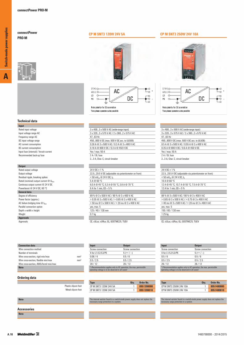
CP M SNT3 120W 24V 5A
3 x 400...3 x 500 V AC (wide-range input) 3 x 320...3 x 575 V AC / 2 x 360...2 x 575 V AC 47...63 Hz 450...800 V DC (max. 500 V DC acc. to UL508) 0.28 A @ 3 x 500 V AC / 0.3 A @ 3 x 400 V AC 0.18 A @ 800 V DC / 0.3 A @ 450 V DCYes / max. 50 A2 A / DI, fuse 2...3 A, Char. C, circuit breaker
24 V DC ± 1 % 22.5...29.5 V DC (adjustable via potentiometer on front) < 50 mVSS @ 24 V DC, IN5 A @ 60 °C 6.0 A @ 45 °C, 5.3 A @ 55 °C, 3.8 A @ 70 °C 6 A for 1 min, ED = 5 %
89 % @ 3 x 500 V AC / 90 % @ 3 x 400 V AC > 0.55 @ 3 x 500 V AC / > 0.65 @ 3 x 400 V AC > 50 ms @ 3 x 500 V AC / > 20 ms @ 3 x 400 V ACyes, max. 5125 / 40 / 130 mm0.7 kg
CE; cULus; cURus; GL; GOSTME25; TUEV
Input OutputScrew connection Screw connection4 for L1/L2/L3/PE 5 (++ / ---)0.08 / 4 0.5 / 60.5 / 2.5 0.5 / 2.528 / 12 26 / 12*) Recommendation applies only to AC operation; the max. permissibleoperating voltage is to be observed in all cases!
Type Qty. Order No.CP M SNT3 120W 24V 5A 1 8951390000CP M SNT3 120W 24V 5A 1 8951390010
The internal varistor found in a switch-mode power supply does not replace the necessary surge protection in a system.
CP M SNT3 250W 24V 10A
3 x 400...3 x 500 V AC (wide-range input) 3 x 320...3 x 575 V AC / 2 x 360...2 x 575 V AC 47...63 Hz 450...800 V DC (max. 500 V DC acc. to UL508) 0.5 A @ 3 x 500 V AC / 0.55 A @ 3 x 400 V AC 0.35 A @ 800 V DC / 0.6 A @ 450 V DCYes / max. 50 A2 A / DI, fuse 2...3 A, Char. C, circuit breaker
24 V DC ± 1 % 22.5...29.5 V DC (adjustable via potentiometer on front) < 50 mVSS @ 24 V DC, IN10 A @ 60 °C 12 A @ 45 °C, 10.7 A @ 55 °C, 7.5 A @ 70 °C 12 A for 1 min, ED = 5 %
89 % @ 3 x 500 V AC / 90 % @ 3 x 400 V AC > 0.65 @ 3 x 500 V AC / > 0.75 @ 3 x 400 V AC > 40 ms @ 3 x 500 V AC / > 20 ms @ 3 x 400 V ACyes, max. 5150 / 60 / 130 mm1.25 kg
CE; cULus; cURus; GL; GOSTME25; TUEV
Input OutputScrew connection Screw connection4 for L1/L2/L3/PE 5 (++ / ---)0.5 / 6 0.5 / 60.5 / 2.5 0.5 / 2.526 / 12 26 / 12*) Recommendation applies only to AC operation; the max. permissibleoperating voltage is to be observed in all cases!
Type Qty. Order No.CP M SNT3 250W 24V 10A 1 8951400000CP M SNT3 250W 24V 10A 1 8951400010
The internal varistor found in a switch-mode power supply does not replace the necessary surge protection in a system.
Switc
h-mod
e pow
er su
pplie
sconnectPower PRO-M

A
A.171460790000 – 2014/2015
connectPower PRO-M
Technical dataInputRated input voltageInput voltage range ACFrequency range ACDC input voltage rangeAC current consumptionDC current consumptionInput fuse (internal) / Inrush currentRecommended back-up fuse
OutputRated output voltageOutput voltageResidual ripple, breaking spikesRated (nominal) output current @ UNom
Continous output current @ 24 V DCPowerboost @ 24 V DC, 60 °CGeneral dataDegree of efficiencyPower factor (approx.)AC failure bridging time @ INom
Parallel connection optionDepth x width x heightWeightApprovalsApprovals
Connection dataWire connection methodNumber of terminalsWire cross-section, rigid min/max mm²Wire cross-section, flexible min/max mm²Wire cross-section, AWG/kcmil min/maxNote
Ordering data
Plastic clip-on footMetal clip-on foot
Note
AccessoriesNote
CP M SNT3 500W 24V 20A
3 x 400...3 x 500 V AC (wide-range input) 3 x 320...3 x 575 V AC / 2 x 360...2 x 575 V AC 47...63 Hz 450...800 V DC (max. 500 V DC acc. to UL508) 0.9 A @ 3 x 500 V AC / 0.95 A @ 3 x 400 V AC 0.7 A @ 800 V DC / 1.2 A @ 450 V DCYes / max. 50 A4 A / DI, fuse 3...5 A, Char. C, circuit breaker
24 V DC ± 1 % 22.5...29.5 V DC (adjustable via potentiometer on front) < 50 mVSS @ 24 V DC, IN20 A @ 60 °C 24 A @ 45 °C, 21.3 A @ 55 °C, 15 A @ 70 °C 24 A for 1 min, ED = 5 %
89 % @ 3 x 500 V AC / 90 % @ 3 x 400 V AC < 0.69 @ 3 x 500 V AC / > 0.82 @ 3 x 400 V AC > 25 ms at 3 x 500 V AC / > 20 ms at 3 x 400 V ACyes, max. 3150 / 121 / 130 mm2.2 kg
CE; cULus; cURus; GL; GOSTME25; TUEV
Input OutputScrew connection Screw connection4 for L1/L2/L3/PE 5 (++ / ---)0.5 / 6 0.5 / 60.5 / 2 0.5 / 2.526 / 10 26 / 10*) Recommendation applies only to AC operation; the max. permissibleoperating voltage is to be observed in all cases!
Type Qty. Order No.CP M SNT3 500W 24V 20A 1 8951410000CP M SNT3 500W 24V 20A 1 8951410010
The internal varistor found in a switch-mode power supply does not replace the necessary surge protection in a system.
CP M SNT3 1000W 24V 40A
3 x 400...3 x 500 V AC (wide-range input) 3 x 320...3 x 575 V AC / 2 x 360...2 x 575 V AC 47...63 Hz 450...800 V DC (max. 500 V DC acc. to UL508) 2.0 A @ 3 x 500 V AC / 2.5 A @ 3 x 400 V AC 1.3 A @ 800 V DC / 2.4 A @ 450 V DCYes / max. 60 A6 A / DI, fuse 10 A, Char. B, circuit breaker 6...8 A, Char, C, circuit breaker
24 V DC ± 1 % 22.5...29.5 V DC (adjustable via potentiometer on front) < 50 mVSS @ 24 V DC, IN40 A @ 60 °C 48 A @ 45 °C, 42.7 A @ 55 °C, 30 A @ 70 °C 48 A for 1 min, ED = 5 %
91 % @ 3 x 500 V AC / 91 % @ 3 x 400 V AC > 0.6 @ 3 x 500 V AC / > 0.6 @ 3 x 400 V AC > 25 ms at 3 x 500 V AC / > 20 ms at 3 x 400 V ACyes, max. 3150 / 180 / 130 mm4 kg
CE; cULus; cURus; GL; TUEV
Input OutputScrew connection Screw connection4 for L1/L2/L3/PE 5 (++ / ---)0.5 / 6 0.5 / 160.5 / 2.5 0.5 / 1026 / 10 22 / 6*) Recommendation applies only to AC operation; the max. permissibleoperating voltage is to be observed in all cases!
Type Qty. Order No.CP M SNT3 1000W 24V 40A 1 8951420000CP M SNT3 1000W 24V 40A 1 8951420010
The internal varistor found in a switch-mode power supply does not replace the necessary surge protection in a system.
Switc
h-mod
e pow
er su
pplie
s
connectPower PRO-M

A
A.18 1460790000 – 2014/2015
connectPower PRO-M
Technical dataInputRated input voltageInput voltage range ACFrequency range ACDC input voltage rangeAC current consumptionDC current consumptionInput fuse (internal) / Inrush currentRecommended back-up fuse
OutputRated output voltageOutput voltageResidual ripple, breaking spikesRated (nominal) output current @ UNom
Continous output current @ 24 V DCPowerboost @ 24 V DC, 60 °CGeneral dataDegree of efficiencyPower factor (approx.)AC failure bridging time @ INom
Parallel connection optionDepth x width x heightWeightApprovalsApprovals
Connection dataWire connection methodNumber of terminalsWire cross-section, rigid min/max mm²Wire cross-section, flexible min/max mm²Wire cross-section, AWG/kcmil min/maxNote
Ordering data
Metal clip-on foot
Note
AccessoriesNote
CP M SNT 500W 36V 13.5A
100...240 V AC (wide-range input) 85…264 V AC (Derating @ 100 V AC) 47...63 Hz 80…370 V DC (Derating @ 120 V DC) 2.4 A @ 230 V AC / 4.8 A @ 115 V AC 1.5 A @ 370 V DC / 4.6 A @ 120 V DCYes / 5 A6 A / DI, fuse 16 A, Char. B, circuit breaker 6...8 A, Char. C, circuit breaker
36 V DC ± 1 % 29...38 V DC (adjustable via potentiometer on front) < 50 mVss @ 36 V DC 13.5 A @ 60°C
90 % at 230 V AC / > 85 % at 115 V AC > 0.98 @ 230 V AC / > 0.99 @ 115 V AC > 20 ms @ 230 V AC / > 20 ms @ 115 V ACyes, max. 3150 / 121 / 130 mm2.2 kg
CE; GOSTME25; TUEV
Input OutputScrew connection Screw connection3 for L/N/PE 5 (++ / ---)0.5 / 6 0.5 / 60.5 / 2.5 0.5 / 2.526 / 10 26 / 10*) Recommendation applies only to AC operation; the max. permissibleoperating voltage is to be observed in all cases!
Type Qty. Order No.CP M SNT 500W 36V 13.5A 1 1412540010
The internal varistor found in a switch-mode power supply does not replace the necessary surge protection in a system.
Switc
h-mod
e pow
er su
pplie
sconnectPower PRO-M

A
A.191460790000 – 2014/2015
PRO-M: diode, capacity and relay modules
Technical dataInputRated input voltage / DC input voltage rangeInput currentOutputRated output voltage / Output voltageRated (nominal) output current @ UNom
Continous output current @ 24 V DCVoltage monitoring / Floating contactSwitching thresholds
General dataDegree of efficiencyDepth x width x height / WeightAmbient temperature (operational) / Storage temperatureHumidityProtection degree / Class of protection / Pollution severityInsulation voltageMTBF Mounting position, installation notice
EMC / shock / vibrationNoise emission acc. to EN55022Interference immunity test acc. to
Resistance to vibration / ShockElectrical safety (applied standards)Electrical machine equipmentFor use with electronic equipmentSafety extra-low voltageApprovalsApprovals
Connection dataWire connection methodNumber of terminalsWire cross-section, rigid min/max mm²Wire cross-section, flexible min/max mm²Wire cross-section, AWG/kcmil min/maxNote
Ordering data
Plastic clip-on footMetal clip-on foot
Note
AccessoriesNote
CP M DM20
24 V DC / 18…30 V DC 2 x 10 A or 1 x 20 A
24 V DC ± 1 % / Input voltage - 0.7 V 20 A @ 60 °C 24 A @ 45 °C, 22.5 A @ 55 °C, 15 A @ 70 °C Yes, In both inputs / Yes21.6 V DC, relay is on for Power Good, 20.4 V DC, relay is off for Power Fail
> 97% @ 24 V input voltage 150 / 34 / 130 mm / 0.3 kg-25 °C...+70 °C / -40 °C...+85 °C5...95 %, no condensation IP 20 / III, with no ground connection, for SELV / 20.5 kV Input/output housing
> 500,000 h acc. to IEC 1709 (SN29500 Horizontal on TS35 DIN rail. 50 mm clearance top & bottom for air circ. Can mount side by side with no space in between.
Class BEN 61000-4-2 (ESD)|EN 61000-4-3 and EN 61000-4-8 (fields)|EN 61000-4-4 (burst)|EN 61000-4-5 (surge)|EN 61000-4-6 (conducted)
1 g according to EN50178 / 15 g In all directions
Acc. to EN60204Acc. to EN50178 / VDE0160SELV acc. to EN60950, PELV acc. to EN60204
cCSAus; CE; cULus; GL; GOSTME25
Input OutputScrew connection Screw connection4 (1+, 2+, 1-, 2-) 4 (3 +, 4 +, 3 -, 4 -)0.5 / 6 0.5 / 60.5 / 2.5 0.5 / 2.526 / 12 26 / 12
Type Qty. Order No.CP M DM20 1 1222210000CP M DM20 1 1222210010
CP M DM40
24 V DC / 18…30 V DC 2 x 20 A or 1 x 40 A
24 V DC ± 1 % / Input voltage - 0.7 V 40 A @ 60 °C 48 A @ 45 °C, 45 A @ 55 °C, 30 A @ 70 °C Yes, In both inputs / Yes21.6 V DC, relay is on for Power Good, 20.4 V DC, relay is off for Power Fail
> 97% @ 24 V input voltage 150 / 60 / 130 mm / 0.6 kg-25 °C...+70 °C / -40 °C...+85 °C5...95 %, no condensation IP 20 / III, with no ground connection, for SELV / 20.5 kV Input/output housing
> 500,000 h acc. to IEC 1709 (SN29500 Horizontal on TS35 DIN rail. 50 mm clearance top & bottom for air circ. Can mount side by side with no space in between.
Class BEN 61000-4-2 (ESD)|EN 61000-4-3 and EN 61000-4-8 (fields)|EN 61000-4-4 (burst)|EN 61000-4-5 (surge)|EN 61000-4-6 (conducted)
1 g according to EN50178 / 15 g In all directions
Acc. to EN60204Acc. to EN50178 / VDE0160SELV acc. to EN60950, PELV acc. to EN60204
cCSAus; CE; cULus; GL; GOSTME25
Input OutputScrew connection Screw connection4 (1+, 2+, 1-, 2-) 4 (3 +, 4 +, 3 -, 4 -)0.5 / 16 0.5 / 162.5 / 10 2.5 / 1022 / 6 22 / 6
Type Qty. Order No.CP M DM40 1 1222220000CP M DM40 1 1222220010
Switc
h-mod
e pow
er su
pplie
s
connectPower PRO-M

A
A.20 1460790000 – 2014/2015
PRO-M: diode, capacity and relay modules
Technical dataInputRated input voltageDC input voltage rangeOutputVoltage monitoringSwitching thresholds
Floating contactGeneral dataDepth x width x heightWeightAmbient temperature (operational) / Storage temperatureHumidityProtection degreeClass of protectionPollution severityInsulation voltageMTBF Mounting position, installation noticeEMC / shock / vibrationNoise emission acc. to EN55022Interference immunity test acc. to
Resistance to vibration / ShockElectrical safety (applied standards)Electrical machine equipmentFor use with electronic equipmentSafety extra-low voltageApprovalsApprovals
Connection dataWire connection methodNumber of terminalsWire cross-section, rigid min/max mm²Wire cross-section, flexible min/max mm²Wire cross-section, AWG/kcmil min/maxNote
Ordering data
Note
AccessoriesNote
CP M RM24
24 V DC 18…30 V DC
Yes21.6 V DC, relay is on for Power Good, 20.4 V DC, relay is off for Power Fail Yes
22 / 33 / 28 mm75 kg-25 °C...+70 °C / -40 °C...+85 °C5...95 %, no condensation IP 20III, with no ground connection, for SELV20.5 kV Input/output housing
> 500,000 h acc. to IEC 1709 (SN29500 Plugged in to the front of the PRO-M power supply
Class BEN 61000-4-2 (ESD)|EN 61000-4-3 and EN 61000-4-8 (fields)|EN 61000-4-4 (burst)|EN 61000-4-5 (surge)|EN 61000-4-6 (conducted)|EN 61000-4-11 (dips) 1 g according to EN50178 / 15 g In all directions
Acc. to EN60204Acc. to EN50178 / VDE0160SELV acc. to EN60950, PELV acc. to EN60204
CE; cURus; GL; GOSTME25
Input OutputPUSH IN PUSH IN
3 (CO contacts)0.2 / 1.50.2 / 1.524 / 16
Type Qty. Order No.CP M RM24 1 1222230000
Switc
h-mod
e pow
er su
pplie
sconnectPower PRO-M

A
A.211460790000 – 2014/2015
PRO-M: diode, capacity and relay modules
Technical dataInputRated input voltage / DC input voltage rangeOutputPeak current output / Recovery time for the capacitorSwitching thresholds
Floating contactGeneral dataDepth x width x height / WeightAmbient temperature (operational) / Storage temperatureHumidityProtection degreeClass of protectionPollution severityInsulation voltageMTBF Mounting position, installation notice
EMC / shock / vibrationNoise emission acc. to EN55022Interference immunity test acc. to
Resistance to vibration / ShockElectrical safety (applied standards)Electrical machine equipmentFor use with electronic equipmentSafety extra-low voltageApprovalsApprovals
Connection dataWire connection methodNumber of terminalsWire cross-section, rigid min/max mm²Wire cross-section, flexible min/max mm²Wire cross-section, AWG/kcmil min/maxNote
Ordering data
Plastic clip-on footMetal clip-on foot
Note
AccessoriesNote
CP M CAP
24 V DC / 18…30 V DC
Depending on the load (typically 40 A for 1 ms) / Approx. 1 sec.21.6 V DC, relay is on for Power Good, 20.4 V DC, relay is off for Power Fail Yes
150 / 34 / 130 mm / 0.4 kg-25 °C...+70 °C / -40 °C...+85 °C5...95 %, no condensation IP 20 III, with no ground connection, for SELV 20.5 kV Input/output housing
> 500,000 h acc. to IEC 1709 (SN29500 Horizontal on TS35 DIN rail. 50 mm clearance top & bottom for air circ. Can mount side by side with no space in between.
Class BEN 61000-4-2 (ESD)|EN 61000-4-3 and EN 61000-4-8 (fields)|EN 61000-4-4 (burst)|EN 61000-4-5 (surge)|EN 61000-4-6 (conducted)|EN 61000-4-11 (dips) 1 g according to EN50178 / 15 g In all directions
Acc. to EN60204Acc. to EN50178 / VDE0160SELV acc. to EN60950, PELV acc. to EN60204
CE; cULus; GL
Input OutputScrew connection Screw connection4 (++--) 3 (CO contacts)0.5 / 6 0.5 / 60.5 / 4 0.5 / 2.526 / 12 26 / 12For low-impedance connections we recommend 2.5 mm².
Type Qty. Order No.CP M CAP 1 1222240000CP M CAP 1 1222240010
Switc
h-mod
e pow
er su
pplie
s
connectPower PRO-M

connectPower PRO-M
Technical dataGeneral technical dataOutput characteristic curve / current limit IU / > 120 % IREarth discharge current < 3.5 mAAmbient temperature (operational) / Storage temperature / Start-up –25 °C…+70 °C / –40 °C…+85 °C / ≥ –40 °CMax. permitted humidity (operational) 5 %…95 % RHDegree of protection IP 20Class of protection I, with PE connectionPollution degree 2Insulation voltage 3 kV AC 1 min. / 2 kV AC 1 min. / 0.5 kV AC 1 min.MTBF > 500,000 h according to IEC 1709 (SN29500)Protection against reverse voltages from the load 30…35 V DCCan be connected in parallel Yes, without diode moduleHousing version Metal, corrosion resistantSignal indication Operations, green/red LEDMounting position, installation notice Horizontal on TS 35 mounting rail, with 50 mm of clearance at top and
bottom for air circulation. Can be mounted side by side with no space in between. Suitable for installation in rotating systems.
EMC / shock / vibrationNoise emission acc. to EN55022 Class BNoise immunity tests acc. to EN61000-4-2 (ESD), EN61000-4-3 and EN61000-4-8 (Fields),
EN61000-4-4 (Burst), EN61000-4-5 (Surge), EN610004-6 (conducted), EN61000-4-11 (Dips)
Limiting of mains voltage harmonic currents according to EN61000-3-2Resistance against vibration and shock according to EN50178, Shock: 5 g in all directionsElectrical safety (applied standards)Electrical equipment of machines according to EN60204Safety transformers for switched-mode power units according to EN61558-2-17Safety transformers for switched-mode power units according to EN50178 / VDE0160Safety extra low voltage SELV according to EN60950, PELV according to EN60204Protective separation / protection against electrical shock VDE0100-410 / according to DIN57100-410Protection against dangerous shock currents according to VDE0106-101
PRO-M: Application solution for wind powerSwitched-mode power supply with wide-range input
Application solution for wind power:
• 80 ... 430 V DC input • Alarm contact • Metal snap-on foot
% {
\ u
110
190
90
80
70
60
50 40 80 120 160 200 240 280 320 360 400 440
Voltage derating
DC Input [V]
Pout
[% P
n]
130
120
110
100
90
80
70
60 20 30 40 50 60 70 80
Temperature derating
Ambient temperature [°C]
Pout
[% P
n]
A
Switc
h-mod
e pow
er su
pplie
s
A.22 1460790000 – 2014/2015

A
A.231460790000 – 2014/2015
PRO-M: application solutions for wind power
Technical dataInputRated input voltage / Input voltage range AC
Frequency range ACDC input voltage rangeAC current consumptionDC current consumptionInput fuse (internal)Recommended back-up fuse
OutputRated output voltageOutput voltageResidual ripple, breaking spikesRated (nominal) output current @ UNom
Continous output current @ 24 V DCGeneral dataDegree of efficiencyPower factor (approx.)AC failure bridging time @ INom
Depth x width x height / WeightAdditional equipmentStatus indicatorRelay onffApprovalsApprovals
Connection dataWire connection methodNumber of terminalsWire cross-section, rigid min/max mm²Wire cross-section, flexible min/max mm²Wire cross-section, AWG/kcmil min/maxNote
Ordering data
Note
AccessoriesNote
CP M SNT 250W 24V 10A UW
100...240 V AC (wide-range input) / 85…264 V AC (Derating @ 100 V AC) 47...63 Hz 80…430 V DC 1.2 A @ 230 V AC / 2.4 A @ 115 V AC 0.8 A @ 370 V DC / 2.3 A @ 120 V DCYes4 A / DI, fuse 10 A, Char. B, circuit breaker 3...4 A, Char. C, circuit breaker
24 V DC ± 1 % 22.5...29.5 V DC (adjustable via potentiometer on front) < 50 mVSS @ 24 V DC, IN, <2,4 VSS @ 24 V DC, IN -40 °C10 A @ 60 °C 12 A @ 45 °C, 10.7 A @ 55 °C, 7.5 A @ 70 °C
90 % @ 230 V AC / 87 % @ 115 V AC > 0.99 @ 230 V AC / > 0.97 @ 115 V AC> 20 ms @ 230 V AC / > 20 ms @ 115 V AC155 / 60 / 130 mm / 1.2 Kg
Green LED, Red LEDOutput voltage > 21.6 V / < 20.4 V
CE; cULus; GL; GOSTME25; TUEV
Input OutputScrew connection Screw connection3 for L/N/PE 6 (+,+,-,-,COM,NO)0.5 / 6 0.5 / 60.5 / 2.5 0.5 / 2.526 / 12 26 / 12
Type Qty. Order No.CP M SNT 250W 24V 10AUW 1 1165480010
The internal varistor found in a switch-mode power supply does not replace the necessary surge protection in a system.
Switc
h-mod
e pow
er su
pplie
s
connectPower PRO-M

Small metal foot
Type Order No.MTA 30 MF 1251320000
Small wall mounting
Type Order No.CP A WALLADAPTER 30 MM 1461870000
Markers
Type Colour Qty. Order No.SM 18/9.5 K MC NE WS white 200 1248580000
EndwinkelFor DIN rail TS 35
Polyamide with fibre glass, screwable Colour Torque Qty. Order No.WEW 35/1 SW black 1.2 Nm 50 1162600000
Large metal foot
Type Order No.MTA 45 MF 1251310000
Large wall mounting
Type Order No.CP A WALLADAPTER 45 MM 1461850000
Small plastic foot
Type Order No.MTA 30 BK 1168970000
Large plastic foot
Type Order No.MTA 45 BK 1962250000
Small screwdriver
Type Blade type Size/AF a b c Order No.SDIK PH1 1.00 80 9008570000SDIS 0.5X3.0X100 B 0.5 3 100 9008380000
PRO M - Accessories
Large screwdriver
Type Blade type Size/AF a b c Order No.SDIS 1.0X5.5X125 B 1 5.5 125 9008410000
A
Switc
h-mod
e pow
er su
pplie
s
A.24 1460790000 – 2014/2015

A
Switc
h-mod
e pow
er su
pplie
s
A.251460790000 – 2014/2015

connectPower PRO-H
connectPower PRO-H
L (+)
N (–)
PE DCAC –
–13
Data Link 14
DC OK
++
Max. limiting average on state current [A]Type\Temp. 40 °C 50 °C 60 °C 70 °C1 ph 12 V / 6 A 6.0 5.7 5.4 4.51 ph 12 V / 12 A 12.0 9.5 7.0 3.71 ph 24 V / 3.8 A 3.8 3.1 2.5 1.71 ph 24 V / 7.5 A 7.5 6.3 5.0 3.31 ph 24 V / 15 A 15.0 12.5 10.0 6.71 ph 24 V / 25 A 25.0 22.5 20.0 13.31 ph 36 V / 16.5 A 16.5 15.0 13.3 9.01 ph 48 V / 2 A 2.0 1.6 1.3 0.81 ph 48 V / 4 A 4.0 3.3 2.5 1.71 ph 48 V / 7.5 A 7.5 6.3 5.0 3.31 ph 48 V / 12.5 A 12.5 11.3 10.0 7.51-2 ph 24 V / 7.5 A 7.5 6.3 5.0 3.31-2 ph 24 V / 15 A 15.0 12.5 10.0 6.71-2 ph 24 V / 25 A 25.0 22.5 20.0 13.3
Technical dataGeneral technical dataCurrent limiting > 100 % Irated
Ambient temp. operating / storage temperature -25…+70 °C -25 °C…+85 °CMax. perm. air humidity (operation) 95 % RHDegree of protection / Class of protection IP 20 / I, with PE connectionPollution degree 2Insulation voltage input/output 4 kV I/O 2 kV I/earth 0.5 kV O/earthMTBF according to IEC 61709 CP T … 70/90 W > 1.8 Mio. h
CP T … 140 W > 1.2 Mio. hCP T … 180/360/600 W > 0.9 Mio. h
Protection against reverse voltages from the load 16 V DC / 35 V DC / 63 V DCParallel connection option yes, without diode moduleHousing version metal, corrosion resistantOverload protection Thermal protection, autom. restartShort circuit protection Unlimited, autom. restartIndication Dual LED Operational: Green LED; Error: Red LEDMounting position, installation notice Horizontal on TS 35 mounting rail, with 80 mm space at top and bottom.
Side by side mounting with 50 mm clearance.Stripping length (rated connection) 7 mmSignal indicationPower Good Signal Trigger point 12 V Version 9…11 V DC
24 V Version 18...22 V DC 48 V Version 36...44 V DC
Potential free, floating signal contact NO contact 30 V DC / 1.0 A max. for 12/24 V DC modules 48 V DC/ 0.5 A max. for 36/48 V DC modules
Active output signal 70 W 11 V DC ± 1 V DC / 20 mA max.140 W 11 V DC ± 1 V DC / 40 mA max.90 W 22 V DC ± 2 V DC / 10 mA max.180/360/600 W 24 V DC 22 V DC± 2 V DC / 20 mA max. 180/360/600 W 48 V DC 44 V DC± 4 V DC / 15 mA max.
EMC / shock / vibrationNoise emission acc. to EN55022 Class BNoise immunity tests acc. to EN61000-4-2 (ESD), EN61000-4-3 and EN61000-4-8 (Fields),
EN61000-4-4 (Burst), EN61000-4-5 (Surge), EN610004-6 (conducted), EN61000-4-11 (Dips)
Limiting of mains voltage harmonic currents according to EN61000-3-2Vibration IEC 60068-2-6 3 axes, Sinus, 10…55 Hz, 1 g, 1 oct./minShock IEC 60068-2-27 3 axes, 15 g, half sinus, 11 msElectrical safety (applied standards)Electrical equipment of machines according to EN60204Safety transformers for switched-mode power units according to EN61558-2-4Machinery with electronic equipment according to EN50178 Safety extra low voltage SELV according to EN60950
Temperature [°C]
40
50
60
70
Outp
ut P
ower
[% P
max]
40 50 60 70
80
90
100
CP T SNT...
-25
70 W140 W
90 W180 W360 W
600 W
Input Voltage [V AC]
40
50
60
Outp
ut P
ower
[% P
max]
70
80
90
100
85 90 100 110 115 132 187 230 264
% { \ | CBScheme
A
Switc
h-mod
e pow
er su
pplie
s
A.26 1460790000 – 2014/2015

A
A.271460790000 – 2014/2015
connectPower PRO-H
Technical dataInputRated input voltageInput voltage range ACFrequency range ACAC current consumptionInput fuse (internal) / Inrush currentRecommended back-up fuseOutputRated output voltageOutput voltageResidual ripple, breaking spikesRated (nominal) output current @ UNom
Continous output current @ 24 V DCGeneral dataDegree of efficiencyAC failure bridging time @ INom
Parallel connection optionDepth x width x heightWeightApprovalsApprovals
Connection dataWire connection methodNumber of terminalsWire cross-section, rigid min/max mm²Wire cross-section, flexible min/max mm²Wire cross-section, AWG/kcmil min/maxNote
Ordering data
Note
AccessoriesNote
CP T SNT 70W 12V 6A
L (+)
N (–)
PE DCAC –
13Data Link 14
DC OK
+
100...240 V AC (wide-range input) 85...264 V AC 47...63 Hz 1 A @ 230 V AC, 2 A @ 115 V AC 4 A / < 20 A (230 V AC) 6…16 A, char. B, circuit breaker
12 V DC ± 1 % 12...14 V DC (adjustable via potentiometer on front)100 mVSS @ 12 V DC, Inom
6 A @ 40 °C 6 A @ 40 °C, 5.4 A @ 60 °C, 4.5 A @ 70 °C
typ. 82 % @ 230 V AC min. 20 ms @ 230 V AC, min. 10 ms @ 115 V AC yes, max. 5110 / 35 / 110 mm0.5 kg
BVATEX; CE; CSA; cULus; cURus; GOSTME25
Input OutputScrew connection Screw connection3 for L/N/PE 2 (+ / -)0.5 / 2.5 1 / 2.50.5 / 2.5 1 / 2.524 / 12 18 / 12
Type Qty. Order No.CP T SNT 70W 12V 6A 1 1105430000
The internal varistor found in a switch-mode power supply does not replace the necessary surge protection in a system.
CP T SNT 140W 12V 12A
L (+)
N (–)
PE DCAC –
–13
Data Link 14
DC OK
++
100…240 V AC (auto-select) 85…132 V AC, 187…264 V AC 47...63 Hz 1.4 A @ 230 V AC, 2.5 A @ 115 V AC 4 A / < 20 A (230 V AC) 6…16 A, char. B, circuit breaker
12 V DC ± 1 % 12...14 V DC (adjustable via potentiometer on front)100 mVSS @ 12 V DC, Inom
12 A @ 40 °C 12 A @ 40 °C, 7 A @ 60 °C, 3.7 A @ 70 °C
typ. 85 % @ 230 V AC min. 20 ms @ 230 V AC, min. 10 ms @ 115 V AC yes, max. 5110 / 54 / 110 mm0.7 kg
BVATEX; CE; CSA; cULus; cURus; GOSTME25
Input OutputScrew connection Screw connection3 for L/N/PE 7 (+ / - / Signal)0.5 / 2.5 1 / 2.50.5 / 2.5 1 / 2.524 / 12 18 / 12
Type Qty. Order No.CP T SNT 140W 12V 12A 1 1105440000
The internal varistor found in a switch-mode power supply does not replace the necessary surge protection in a system.
Switc
h-mod
e pow
er su
pplie
s
connectPower PRO-H

A
A.28 1460790000 – 2014/2015
connectPower PRO-H
Technical dataInputRated input voltageInput voltage range ACFrequency range ACAC current consumptionInput fuse (internal) / Inrush currentRecommended back-up fuseOutputRated output voltageOutput voltageResidual ripple, breaking spikesRated (nominal) output current @ UNom
Continous output current @ 24 V DCGeneral dataDegree of efficiencyAC failure bridging time @ INom
Parallel connection optionDepth x width x heightWeightApprovalsApprovals
Connection dataWire connection methodNumber of terminalsWire cross-section, rigid min/max mm²Wire cross-section, flexible min/max mm²Wire cross-section, AWG/kcmil min/maxNote
Ordering data
Note
AccessoriesNote
CP T SNT 90W 24V 3.8A
L (+)
N (–)
PE DCAC –
13Data Link 14
DC OK
+
100...240 V AC (wide-range input) 85...264 V AC 47...63 Hz 1 A @ 230 V AC, 2.1 A @ 115 V AC 4 A / < 20 A (230 V AC) 6…16 A, char. B, circuit breaker
24 V DC ± 1 % 24...28 V DC (adjustable via potentiometer on front)100 mVPP @ 24 V DC, Inenn
3.8 A @ 40 °C 3.8 A @ 40 °C, 2.5 A @ 60 °C, 1.7 A @ 70 °C
typ. 85 % @ 230 V AC min. 20 ms @ 230 V AC, min. 10 ms @ 115 V AC yes, max. 5110 / 35 / 110 mm0.5 kg
BVATEX; CE; CSA; cULus; cURus; GOSTME25
Input OutputScrew connection Screw connection3 for L/N/PE 2 (+ / -)0.5 / 2.5 1 / 2.50.5 / 2.5 0.5 / 2.524 / 12 24 / 12
Type Qty. Order No.CP T SNT 90W 24V 3,8A 1 1105790000
The internal varistor found in a switch-mode power supply does not replace the necessary surge protection in a system.
CP T SNT 90W 24V 3.8A CL2Class 2, UL 1310
L (+)
N (–)
PE DCAC –
13Data Link 14
DC OK
+
100...240 V AC (wide-range input) 85...264 V AC 47...63 Hz 1 A @ 230 V AC, 2.1 A @ 115 V AC 4 A / < 20 A (230 V AC) 6…16 A, char. B, circuit breaker
24 V DC ± 1 % 24...28 V DC (adjustable via potentiometer on front)100 mVPP @ 24 V DC, Inenn
3.8 A @ 40 °C 3.8 A @ 40 °C, 2.5 A @ 60 °C, 1.7 A @ 70 °C
typ. 85 % @ 230 V AC min. 20 ms @ 230 V AC, min. 10 ms @ 115 V AC yes, max. 5110 / 35 / 110 mm0.5 kg
CE; cULus; GOSTME25
Input OutputScrew connection Screw connection3 for L/N/PE 2 (+ / -)0.5 / 2.5 1 / 2.50.5 / 2.5 0.5 / 2.524 / 12 24 / 12
Type Qty. Order No.CP T SNT 90W 24V3,8ACL2 1 1194410000
The internal varistor found in a switch-mode power supply does not replace the necessary surge protection in a system.
Switc
h-mod
e pow
er su
pplie
sconnectPower PRO-H

A
A.291460790000 – 2014/2015
connectPower PRO-H
Technical dataInputRated input voltageInput voltage range ACFrequency range ACAC current consumptionInput fuse (internal) / Inrush currentRecommended back-up fuseOutputRated output voltageOutput voltageResidual ripple, breaking spikesRated (nominal) output current @ UNom
Continous output current @ 24 V DCGeneral dataDegree of efficiencyAC failure bridging time @ INom
Parallel connection optionDepth x width x heightWeightApprovalsApprovals
Connection dataWire connection methodNumber of terminalsWire cross-section, rigid min/max mm²Wire cross-section, flexible min/max mm²Wire cross-section, AWG/kcmil min/maxNote
Ordering data
Note
AccessoriesNote
CP T SNT 180W 24V 7.5A
L (+)
N (–)
PE DCAC –
–13
Data Link 14
DC OK
++
100…240 V AC (auto-select) 85…132 V AC, 187…264 V AC 47...63 Hz 1.4 A @ 230 V AC, 2.5 A @ 115 V AC 4 A / < 20 A (230 V AC) 6…16 A, char. B, circuit breaker
24 V DC ± 1 % 24...28 V DC (adjustable via potentiometer on front)100 mVPP @ 24 V DC, Inenn
7.5 A @ 40 °C 7.5 A @ 40 °C, 5 A @ 60 °C, 3.3 A @ 70 °C
typ. 88 % @ 230 V AC min. 20 ms @ 230 V AC, min. 10 ms @ 115 V AC yes, max. 5110 / 54 / 110 mm0.7 kg
BVATEX; CE; CSA; cULus; cURus; GOSTME25
Input OutputScrew connection Screw connection3 for L/N/PE 7 (+ / - / Signal)0.5 / 2.5 1 / 2.50.5 / 2.5 0.5 / 2.524 / 12 24 / 12
Type Qty. Order No.CP T SNT 180W 24V 7,5A 1 1105810000
The internal varistor found in a switch-mode power supply does not replace the necessary surge protection in a system.
CP T SNT 360W 24V 15A
L (+)
N (–)
PE DCAC –
–13
Data Link 14
DC OK
++
100…240 V AC (auto-select) 85…132 V AC, 187…264 V AC 47...63 Hz 2.5 A @ 230 V AC, 5 A @ 115 V AC 6.3 A / < 25 A (230 V AC) 10…16 A, char. B, circuit breaker
24 V DC ± 1 % 24...28 V DC (adjustable via potentiometer on front)100 mVPP @ 24 V DC, Inenn
15 A @ 40 °C 15 A @ 40 °C, 10 A @ 60 °C, 6.7 A @ 70 °C
typ. 87 % @ 230 V AC min. 20 ms @ 230 V AC, min. 10 ms @ 115 V AC yes, max. 5110 / 80 / 110 mm1.1 kg
BVATEX; CE; CSA; cULus; cURus; GOSTME25
Input OutputScrew connection Screw connection3 for L/N/PE 7 (+ / - / Signal)0.5 / 2.5 1 / 2.50.5 / 2.5 1 / 2.524 / 12 18 / 12
Type Qty. Order No.CP T SNT 360W 24V 15A 1 1105820000
The internal varistor found in a switch-mode power supply does not replace the necessary surge protection in a system.
Switc
h-mod
e pow
er su
pplie
s
connectPower PRO-H

A
A.30 1460790000 – 2014/2015
connectPower PRO-H
Technical dataInputRated input voltageInput voltage range ACFrequency range ACAC current consumptionInput fuse (internal) / Inrush currentRecommended back-up fuseOutputRated output voltageOutput voltageResidual ripple, breaking spikesRated (nominal) output current @ UNom
Continous output current @ 24 V DCGeneral dataDegree of efficiencyAC failure bridging time @ INom
Parallel connection optionDepth x width x heightWeightApprovalsApprovals
Connection dataWire connection methodNumber of terminalsWire cross-section, rigid min/max mm²Wire cross-section, flexible min/max mm²Wire cross-section, AWG/kcmil min/maxNote
Ordering data
Note
AccessoriesNote
CP T SNT 600W 24V 25A
L (+)
N (–)
PE DCAC –
–13
Data Link 14
DC OK
++
100…240 V AC (auto-select) 85…132 V AC, 187…264 V AC 47...63 Hz 5 A @ 230 V AC, 10 A @ 115 V AC 12 A / < 30 A (230 V AC) 16…25 A, char. B, circuit breaker
24 V DC ± 1 % 24...28 V DC (adjustable via potentiometer on front)100 mVPP @ 24 V DC, Inenn
25 A @ 40 °C 25 A @ 40 °C, 20 A @ 60 °C, 13.3 A @ 70 °C
typ. 89 % @ 230 V AC min. 20 ms @ 230 V AC, min. 10 ms @ 115 V AC yes, max. 5125 / 165 / 125 mm2.8 kg
BVATEX; CE; CSA; cULus; cURus; GOSTME25
Input OutputScrew connection Screw connection3 for L/N/PE 7 (+ / - / Signal)1 / 4 1 / 2.51 / 4 2.5 / 418 / 10 12 / 10
Type Qty. Order No.CP T SNT 600W 24V 25A 1 1105840000
The internal varistor found in a switch-mode power supply does not replace the necessary surge protection in a system.
Switc
h-mod
e pow
er su
pplie
sconnectPower PRO-H

A
A.311460790000 – 2014/2015
connectPower PRO-H
Technical dataInputRated input voltageInput voltage range ACFrequency range ACAC current consumptionInput fuse (internal) / Inrush currentRecommended back-up fuseOutputRated output voltageOutput voltageResidual ripple, breaking spikesRated (nominal) output current @ UNom
Continous output current @ 24 V DCGeneral dataDegree of efficiencyAC failure bridging time @ INom
Parallel connection optionDepth x width x heightWeightApprovalsApprovals
Connection dataWire connection methodNumber of terminalsWire cross-section, rigid min/max mm²Wire cross-section, flexible min/max mm²Wire cross-section, AWG/kcmil min/maxNote
Ordering data
Note
AccessoriesNote
CP T SNT 90W 48V 2A
L (+)
N (–)
PE DCAC –
13Data Link 14
DC OK
+
100...240 V AC (wide-range input) 85...264 V AC 47...63 Hz 1 A @ 230 V AC, 2.1 A @ 115 V AC 4 A / < 20 A (230 V AC) 6…16 A, char. B, circuit breaker
48 V DC ± 1 % 48...56 V DC (adjustable via potentiometer on front)100 mVSS @ 48 V DC, INenn
2 A @ 40 °C 2 A @ 40 °C, 1.3 A @ 60 °C, 0.8 A @ 70 °C
typ. 87 % @ 230 V AC min. 20 ms @ 230 V AC, min. 10 ms @ 115 V AC yes, max. 5110 / 35 / 110 mm0.5 kg
BVATEX; CE; cULus; GOSTME25
Input OutputScrew connection Screw connection3 for L/N/PE 2 (+ / -)0.5 / 2.5 1 / 2.50.5 / 2.5 0.5 / 2.524 / 12 24 / 12
Type Qty. Order No.CP T SNT 90W 48V 2A 1 1194420000
The internal varistor found in a switch-mode power supply does not replace the necessary surge protection in a system.
CP T SNT 180W 48V 4A
L (+)
N (–)
PE DCAC –
–13
Data Link 14
DC OK
++
100…240 V AC (auto-select) 85…132 V AC, 187…264 V AC 47...63 Hz 1.4 A @ 230 V AC, 2.5 A @ 115 V AC 4 A / < 25 A (230 V AC) 6…16 A, char. B, circuit breaker
48 V DC ± 1 % 48...56 V DC (adjustable via potentiometer on front)100 mVSS @ 48 V DC, INenn
4 A @ 40 °C 4 A @ 40 °C, 2.5 A @ 60 °C, 1.7 A @ 70 °C
typ. 90 % @ 230 V AC min. 20 ms @ 230 V AC, min. 10 ms @ 115 V AC yes, max. 5110 / 54 / 110 mm0.7 kg
BVATEX; CE; CSA; cULus; cURus; GOSTME25
Input OutputScrew connection Screw connection3 for L/N/PE 7 (+ / - / Signal)0.5 / 2.5 1 / 2.50.5 / 2.5 0.5 / 2.524 / 12 24 / 12
Type Qty. Order No.CP T SNT 180W 48V 4A 1 1105850000
The internal varistor found in a switch-mode power supply does not replace the necessary surge protection in a system.
Switc
h-mod
e pow
er su
pplie
s
connectPower PRO-H

A
A.32 1460790000 – 2014/2015
connectPower PRO-H
Technical dataInputRated input voltageInput voltage range ACFrequency range ACAC current consumptionInput fuse (internal) / Inrush currentRecommended back-up fuseOutputRated output voltageOutput voltageResidual ripple, breaking spikesRated (nominal) output current @ UNom
Continous output current @ 24 V DCGeneral dataDegree of efficiencyAC failure bridging time @ INom
Parallel connection optionDepth x width x heightWeightApprovalsApprovals
Connection dataWire connection methodNumber of terminalsWire cross-section, rigid min/max mm²Wire cross-section, flexible min/max mm²Wire cross-section, AWG/kcmil min/maxNote
Ordering data
Note
AccessoriesNote
CP T SNT 360W 48V 7.5A
L (+)
N (–)
PE DCAC –
–13
Data Link 14
DC OK
++
100…240 V AC (auto-select) 85…132 V AC, 187…264 V AC 47...63 Hz 2.5 A @ 230 V AC, 5 A @ 115 V AC 6.3 A / < 25 A (230 V AC) 10…16 A, char. B, circuit breaker
48 V DC ± 1 % 48...56 V DC (adjustable via potentiometer on front)100 mVSS @ 48 V DC, INenn
7.5 A @ 40 °C 7.5 A @ 40 °C, 5 A @ 60 °C, 3.3 A @ 70 °C
typ. 89 % @ 230 V AC min. 20 ms @ 230 V AC, min. 10 ms @ 115 V AC yes, max. 5125 / 80 / 125 mm1.1 kg
BVATEX; CE; CSA; cULus; cURus; GOSTME25
Input OutputScrew connection Screw connection3 for L/N/PE 7 (+ / - / Signal)0.5 / 2.5 1 / 2.50.5 / 2.5 1 / 2.524 / 12 18 / 12
Type Qty. Order No.CP T SNT 360W 48V 7,5A 1 1105860000
The internal varistor found in a switch-mode power supply does not replace the necessary surge protection in a system.
CP T SNT 600W 48V 12.5A
L (+)
N (–)
PE DCAC –
–13
Data Link 14
DC OK
++
100…240 V AC (auto-select) 85…132 V AC, 187…264 V AC 47...63 Hz 5 A @ 230 V AC, 10 A @ 115 V AC 12 A / < 30 A (230 V AC) 16…25 A, char. B, circuit breaker
48 V DC ± 1 % 48...56 V DC (adjustable via potentiometer on front)100 mVSS @ 48 V DC, INenn
12.5 A @ 40 °C 12.5 A @ 40 °C, 10 A @ 60 °C, 7.5 A @ 70 °C
typ. 91 % @ 230 V AC min. 20 ms @ 230 V AC, min. 10 ms @ 115 V AC yes, max. 5125 / 165 / 125 mm2.8 kg
BVATEX; CE; CSA; cULus; cURus; GOSTME25
Input OutputScrew connection Screw connection3 for L/N/PE 7 (+ / - / Signal)1 / 4 1 / 2.51 / 4 2.5 / 418 / 10 12 / 10
Type Qty. Order No.CP T SNT 600W 48V 12,5A 1 1105870000
The internal varistor found in a switch-mode power supply does not replace the necessary surge protection in a system.
Switc
h-mod
e pow
er su
pplie
sconnectPower PRO-H

A
A.331460790000 – 2014/2015
connectPower PRO-H
Technical dataInputRated input voltageInput voltage range ACFrequency range ACAC current consumptionInput fuse (internal) / Inrush currentRecommended back-up fuseOutputRated output voltageOutput voltageResidual ripple, breaking spikesRated (nominal) output current @ UNom
Continous output current @ 24 V DCGeneral dataDegree of efficiencyAC failure bridging time @ INom
Parallel connection optionDepth x width x heightWeightApprovalsApprovals
Connection dataWire connection methodNumber of terminalsWire cross-section, rigid min/max mm²Wire cross-section, flexible min/max mm²Wire cross-section, AWG/kcmil min/maxNote
Ordering data
Note
AccessoriesNote
CP T SNT2 180W 24V 7.5A
L (+)
N (–)
PE DCAC –
–13
Data Link 14
DC OK
++
100…500 V AC (switchable) 85…132 V AC, 187…550 V AC 50 / 60 Hz
/ < 23 A @ 230 V AC
24 V DC ± 1 % 24...28 V DC (adjustable via potentiometer on front)100 mVPP @ 24 V DC, Inenn
7.5 A @ 40 °C 7.5 A @ 40 °C, 5 A @ 60 °C, 3.3 A @ 70 °C
typ. 88 % min. 20 ms Yes110 / 54 / 110 mm0.7 kg
CE
Input OutputScrew connection Screw connection3 for L/N/PE 4 (++ / --)1 / 4 2.5 / 41 / 4 2.5 / 418 / 10 12 / 10The device is suitable for single-phase and two-phase operation.
Type Qty. Order No.CP T SNT2 180 W 24 V 7,5 A 1 1194480000
The internal varistor found in a switch-mode power supply does not replace the necessary surge protection in a system.
CP T SNT2 360W 24V 15A
L (+)
N (–)
PE DCAC –
–13
Data Link 14
DC OK
++
100…500 V AC (switchable) 85…132 V AC, 187…550 V AC 50 / 60 Hz
/ < 23 A @ 230 V AC
24 V DC ± 1 % 24...28 V DC (adjustable via potentiometer on front)100 mVPP @ 24 V DC, Inenn
15 A @ 40 °C 15 A @ 40 °C, 6.7 A @ 70 °C, 10 A @ 60 °C
typ. 88 % min. 20 ms Yes125 / 80 / 125 mm1.1 kg
CE
Input OutputScrew connection Screw connection3 for L/N/PE 4 (++ / --)1 / 4 2.5 / 41 / 4 2.5 / 418 / 10 12 / 10The device is suitable for single-phase and two-phase operation.
Type Qty. Order No.CP T SNT2 360 W 24 V 15 A 1 1194490000
The internal varistor found in a switch-mode power supply does not replace the necessary surge protection in a system.
Switc
h-mod
e pow
er su
pplie
s
connectPower PRO-H
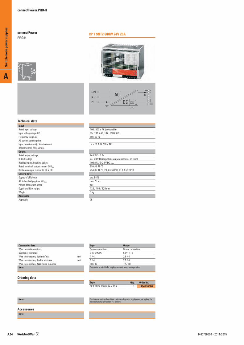
A
A.34 1460790000 – 2014/2015
connectPower PRO-H
Technical dataInputRated input voltageInput voltage range ACFrequency range ACAC current consumptionInput fuse (internal) / Inrush currentRecommended back-up fuseOutputRated output voltageOutput voltageResidual ripple, breaking spikesRated (nominal) output current @ UNom
Continous output current @ 24 V DCGeneral dataDegree of efficiencyAC failure bridging time @ INom
Parallel connection optionDepth x width x heightWeightApprovalsApprovals
Connection dataWire connection methodNumber of terminalsWire cross-section, rigid min/max mm²Wire cross-section, flexible min/max mm²Wire cross-section, AWG/kcmil min/maxNote
Ordering data
Note
AccessoriesNote
CP T SNT2 600W 24V 25A
L (+)
N (–)
PE DCAC –
–13
Data Link 14
DC OK
++
100…500 V AC (switchable) 85…132 V AC, 187…550 V AC 50 / 60 Hz
/ < 50 A @ 230 V AC
24 V DC ± 1 % 24...28 V DC (adjustable via potentiometer on front)100 mVPP @ 24 V DC, Inenn
25 A @ 40 °C 25 A @ 40 °C, 20 A @ 40 °C, 13.3 A @ 70 °C
typ. 88 % min. 20 ms Yes125 / 190 / 125 mm3 kg
CE
Input OutputScrew connection Screw connection3 for L/N/PE 5 (++ / ---)1 / 4 2.5 / 41 / 4 2.5 / 418 / 10 12 / 10The device is suitable for single-phase and two-phase operation.
Type Qty. Order No.CP T SNT2 600 W 24 V 25 A 1 1194310000
The internal varistor found in a switch-mode power supply does not replace the necessary surge protection in a system.
Switc
h-mod
e pow
er su
pplie
sconnectPower PRO-H

A
A.351460790000 – 2014/2015
connectPower PRO-H
Technical dataInputRated input voltageInput voltage range ACFrequency range ACAC current consumptionInput fuse (internal) / Inrush currentRecommended back-up fuseOutputRated output voltageOutput voltageResidual ripple, breaking spikesRated (nominal) output current @ UNom
Continous output current @ 24 V DCGeneral dataDegree of efficiencyAC failure bridging time @ INom
Parallel connection optionDepth x width x heightWeightApprovalsApprovals
Connection dataWire connection methodNumber of terminalsWire cross-section, rigid min/max mm²Wire cross-section, flexible min/max mm²Wire cross-section, AWG/kcmil min/maxNote
Ordering data
Note
AccessoriesNote
CP T RM 10
RemoteON/OFF
DC OK
Data Link PS1
Output
Input 1Data Link PS2
Control
Input 2
24 V DC
24 V DC ± 1 % 24...28 V DC (adjustable via potentiometer on front)100 mVPP @ 24 V DC, Inenn
15 A @ 40 °C
110 / 35 / 110 mm0.4 kg
CE; CSA; cURus; GOSTME25
Input Output
4 (++--) 4 (++ / --)1 / 4 2.5 / 41 / 4 2.5 / 418 / 10 12 / 10
Type Qty. Order No.CP T RM 10 1 1105880000
CP T RM 20
RemoteON/OFF
DC OK
Data Link PS1
Output
Input 1Data Link PS2
Control
Input 2
24 V DC
24 V DC ± 1 % 24...28 V DC (adjustable via potentiometer on front)100 mVPP @ 24 V DC, Inenn
25 A @ 40 °C
110 / 54 / 110 mm0.45 kg
CE; CSA; cURus; GOSTME25
Input Output
4 (++--) 4 (++ / --)1 / 4 2.5 / 41 / 4 2.5 / 418 / 10 12 / 10
Type Qty. Order No.CP T RM 20 1 1105890000
Switc
h-mod
e pow
er su
pplie
s
connectPower PRO-H

PRO H - Accessories
Markers
Type Colour Qty. Order No.SM 18/9.5 K MC NE WS white 200 1248580000
End bracketFor DIN rail TS 35
Polyamide with fibre glass, screwable Colour Torque Qty. Order No.WEW 35/1 SW black 1.2 Nm 50 1162600000
Large screwdriver
Type Blade type Size/AF a b c Order No.SDIK PH2 2.00 100 9008580000SDIS 1.0X5.5X125 B 1 5.5 125 9008410000
Small screwdriver
Type Blade type Size/AF a b c Order No.SDIK PH1 1.00 80 9008570000SDIS 0.5X3.0X100 B 0.5 3 100 9008380000
A
Switc
h-mod
e pow
er su
pplie
s
A.36 1460790000 – 2014/2015

connectPower PRO-H
35.0
110.
0
(1.38)
(4.3
3)
110.0 (4.33)38
.5(1
.52)
80.0
(3.1
5)
25.0(0.98)
5.0
(0.2
0)
5.0(0.20)
Output- - + +
DC IN 1- + - +
DC IN 2
Inputs ON
24 – 27 V
54.0
110.
0
(2.13)
(4.3
3)
110.0 (4.33)
25.0(0.98)
5.0
(0.2
0)
14.5(0.57)
38.5
(1.5
2)80
.0(3
.15)
DC 24 V / 25 A
DC IN 1 DC IN 2
Inputs ON
24 �� 27 V
54.0
110.
0
(2.13)
(4.3
3)
110.0 (4.33)
25.0(0.98)
5.0
(0.2
0)
14.5(0.57)
DC ON
O/P ADJ.
DC OK
PE N L
P/S
PS
Remote
38.5
(1.5
2)80
.0(3
.15)
35.0
110.
0
(1.38)
(4.3
3)
110.0 (4.33)
38.5
(1.5
2)80
.0(3
.15)
25.0(0.98)
5.0
(0.2
0)
5.0(0.20)
DC ON
O/P ADJ.
DC OK
PE N L
P/SP S
Remote
CP T RM 10
CP T SNT 70 W / 90 W
CP T RM 20
CP T SNT 180 W / 140 W
PRO-H Dimensional drawings
A
Switc
h-mod
e pow
er su
pplie
s
A.371460790000 – 2014/2015

connectPower PRO-H
80.0
125.
0
(3.15)
(4.9
2)
125.0 (4.92)
45.0
(1.7
7)86
.5(3
.41)
(1.81)
5.0
(0.2
0) 25.0(0.98)
25.0(0.98)
46.0 17.0(0.67)
DC ONO/P ADJ.
DC OK
PE N L
P/SP S
Remote
165.0
125.
0
(6.50)
(4.92
)
125.0 (4.92)
25.0(0.98)
25.0(0.98)
123.0(4.84)
21.0(0.83)
P/S
P S
Remote
DC ONO/P ADJ.DC OK
PE N L
45.0
(1.77
)86
.5(3
.41)
CP T SNT 360 W / 480 W CP T SNT 600 W / 960 W
PRO-H Dimensional drawings
A
Switc
h-mod
e pow
er su
pplie
s
A.38 1460790000 – 2014/2015

A
Switc
h-mod
e pow
er su
pplie
s
A.391460790000 – 2014/2015

A
A.40 1460790000 – 2014/2015
connectPower PRO-E
Technical dataInputInput voltageInput currentInput frequencyInput fuse (internal)Recommended back-up fuseOutputOutput voltageOutput voltage adjustment
Output currentOutput powerResidual ripple, breaking spikesOverload protectionSurge protection Mains failure bridge-over timeControl at 10...100% loadParallel connection optionInsulation coordinationElectrical isolation, output-earthElectrical isolation, input-earthElectrical isolation, input-outputGeneral dataAmbient temperature (operational)
Storage temperatureMax. perm. air humidity (operational)Degree of efficiencyStatus indicatorStandardsEMC standardsMounting position, installation noticeWeightApprovalsScrew connectionConnection cross-section, solid, min. / max.Depth x width x height
Note
Ordering data
Note
AccessoriesNote
CP E SNT 25W 5V 5A
85...264 V AC / 110…370 V DC0.3 A @ 230 V AC / 0.6 A @ 120 V AC47...63 Hzyes / max. 20A1 A at 230 V AC, characteristic curve C
5 V DC± 10% nominal output voltage tolerance, adjustable with potentiometer5 A@5 V DC25 W< 100 mVPP
120~150% Ikonst. of max. output power, automatic restart5.6...6.8 V @ 5 V DC20 ms0.5%Recommended with diode module
0.5 kV1.5 kV3 kV
-20°C…70°C (>50°C derating,refer derated curve); 70% rated load@70°C-20 °C...+85 °C5 %…95 % RH77 % @ 5 V DCOperation, green LEDEN 60950EN 55011, EN 55022, EN 55024, EN 61000-6 /-2, -3Panel mount, screw fix240 gCE
0.34 / 4 mm²91 / 51 / 28 mm
Type Qty. Order No.CP E SNT 25W 5V 5A 1 1202640000
The internal varistor found in a switch-mode power supply does not replace the necessary surge protection in a system.
CP E SNT 25W 12V 2.1A
85...264 V AC / 110…370 V DC0.3 A @ 230 V AC / 0.6 A @ 120 V AC47...63 Hzyes / max. 20A1 A at 230 V AC, characteristic curve C
12 V DC± 10% nominal output voltage tolerance, adjustable with potentiometer2.1 A@12 V DC25 W< 100 mVPP
120~150% Ikonst. of max. output power, automatic restart13.5...16.2 V @ 12 V DC20 ms0.5%Recommended with diode module
0.5 kV1.5 kV3 kV
-20°C…70°C (>50°C derating,refer derated curve); 70% rated load@70°C-20 °C...+85 °C5 %…95 % RH79 % @ 12 V DCOperation, green LEDEN 60950EN 55011, EN 55022, EN 55024, EN 61000-6 /-2, -3Panel mount, screw fix240 gCE
0.34 / 4 mm²91 / 51 / 28 mm
Type Qty. Order No.CP E SNT 25W 12V 2.1A 1 1202630000
The internal varistor found in a switch-mode power supply does not replace the necessary surge protection in a system.
Switc
h-mod
e pow
er su
pplie
sconnectPower PRO-E

A
A.411460790000 – 2014/2015
connectPower PRO-E
Technical dataInputInput voltageInput currentInput frequencyInput fuse (internal)Recommended back-up fuseOutputOutput voltageOutput voltage adjustment
Output currentOutput powerResidual ripple, breaking spikesOverload protectionSurge protection Mains failure bridge-over timeControl at 10...100% loadParallel connection optionInsulation coordinationElectrical isolation, output-earthElectrical isolation, input-earthElectrical isolation, input-outputGeneral dataAmbient temperature (operational)
Storage temperatureMax. perm. air humidity (operational)Degree of efficiencyStatus indicatorStandardsEMC standardsMounting position, installation noticeWeightApprovalsScrew connectionConnection cross-section, solid, min. / max.Depth x width x height
Note
Ordering data
Note
AccessoriesNote
CP E SNT 25W 24V 1.1A
85...264 V AC / 110…370 V DC0.3 A @ 230 V AC / 0.6 A @ 120 V AC47...63 Hzyes / max. 20A1 A at 230 V AC, characteristic curve C
24 V DC± 10% nominal output voltage tolerance, adjustable with potentiometer1.1 A@24 V DC25 W< 100 mVPP
120~150% Ikonst. of max. output power, automatic restart28...32 V @ 24 V DC20 ms0.5%Recommended with diode module
0.5 kV1.5 kV3 kV
-20°C…70°C (>50°C derating,refer derated curve); 70% rated load@70°C-20 °C...+85 °C5 %…95 % RH84 % @ 24 V DCOperation, green LEDEN 60950EN 55011, EN 55022, EN 55024, EN 61000-6 /-2, -3Panel mount, screw fix240 gCE
0.34 / 4 mm²91 / 51 / 28 mm
Type Qty. Order No.CP E SNT 25W 24V 1.1A 1 1202620000
The internal varistor found in a switch-mode power supply does not replace the necessary surge protection in a system.
CP E SNT 25W 48V 0.57A
85...264 V AC / 110…370 V DC0.3 A @ 230 V AC / 0.6 A @ 120 V AC47...63 Hzyes / max. 20A1 A at 230 V AC, characteristic curve C
48 V DC± 10% nominal output voltage tolerance, adjustable with potentiometer0.57 A@48 V DC25 W< 100 mVPP
120~150% Ikonst. of max. output power, automatic restart55...62 V @ 48 V DC20 ms0.5%Recommended with diode module
0.5 kV1.5 kV3 kV
-20°C…70°C (>50°C derating,refer derated curve); 70% rated load@70°C-20 °C...+85 °C5 %…95 % RH83 % @ 48 V DCOperation, green LEDEN 60950EN 55011, EN 55022, EN 55024, EN 61000-6 /-2, -3Panel mount, screw fix240 gCE
0.34 / 4 mm²91 / 51 / 28 mm
Type Qty. Order No.CP E SNT 25W 48V 0.57A 1 1202610000
The internal varistor found in a switch-mode power supply does not replace the necessary surge protection in a system.
Switc
h-mod
e pow
er su
pplie
s
connectPower PRO-E

A
A.42 1460790000 – 2014/2015
connectPower PRO-E
Technical dataInputInput voltageInput currentInput frequencyInput fuse (internal)Recommended back-up fuseOutputOutput voltageOutput voltage adjustment
Output currentOutput powerResidual ripple, breaking spikesOverload protectionSurge protection Mains failure bridge-over timeControl at 10...100% loadParallel connection optionInsulation coordinationElectrical isolation, output-earthElectrical isolation, input-earthElectrical isolation, input-outputGeneral dataAmbient temperature (operational)
Storage temperatureMax. perm. air humidity (operational)Degree of efficiencyStatus indicatorStandardsEMC standardsMounting position, installation noticeWeightApprovalsScrew connectionConnection cross-section, solid, min. / max.Depth x width x height
Note
Ordering data
Note
AccessoriesNote
CP E SNT 50W 5V 10A
85...264 V AC / 110…370 V DC0.6 A @ 230 V AC / 1.2 A @ 120 V AC47...63 Hzyes / max. 20A2 A at 230 V AC, characteristic curve C
5 V DC± 10% nominal output voltage tolerance, adjustable with potentiometer10 A@5 V DC50 W< 100 mVPP
120~150% Ikonst. of max. output power, automatic restart5.6...6.8 V @ 5 V DC20 ms0.5%Recommended with diode module
0.5 kV1.5 kV3 kV
-20°C…70°C (>50°C derating,refer derated curve); 70% rated load@70°C-20 °C...+85 °C5 %…95 % RH78 % @ 5 V DCOperation, green LEDEN 60950EN 55011, EN 55022, EN 55024, EN 61000-6 /-2, -3Panel mount, screw fix310 gCE
0.34 / 4 mm²105 / 100 / 35 mm
Type Qty. Order No.CP E SNT 50W 5V 10A 1 1202590000
The internal varistor found in a switch-mode power supply does not replace the necessary surge protection in a system.
CP E SNT 50 W 12V 4.2A
85...264 V AC / 110…370 V DC0.6 A @ 230 V AC / 1.2 A @ 120 V AC47...63 Hzyes / max. 20A2 A at 230 V AC, characteristic curve C
12 V DC± 10% nominal output voltage tolerance, adjustable with potentiometer4.2 A@12 V DC50 W< 100 mVPP
120~150% Ikonst. of max. output power, automatic restart13.5...16.2 V @ 12 V DC20 ms0.5%Recommended with diode module
0.5 kV1.5 kV3 kV
-20°C…70°C (>50°C derating,refer derated curve); 70% rated load@70°C-20 °C...+85 °C5 %…95 % RH81 % @ 12 V DCOperation, green LEDEN 60950EN 55011, EN 55022, EN 55024, EN 61000-6 /-2, -3Panel mount, screw fix310 gCE
0.34 / 4 mm²105 / 100 / 35 mm
Type Qty. Order No.CP E SNT 50W 12V 4.2A 1 1202580000
The internal varistor found in a switch-mode power supply does not replace the necessary surge protection in a system.
Switc
h-mod
e pow
er su
pplie
sconnectPower PRO-E
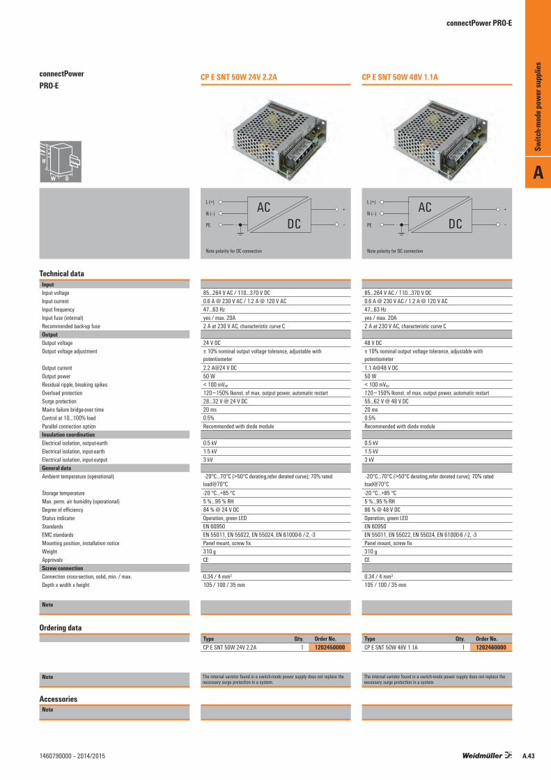
A
A.431460790000 – 2014/2015
connectPower PRO-E
Technical dataInputInput voltageInput currentInput frequencyInput fuse (internal)Recommended back-up fuseOutputOutput voltageOutput voltage adjustment
Output currentOutput powerResidual ripple, breaking spikesOverload protectionSurge protection Mains failure bridge-over timeControl at 10...100% loadParallel connection optionInsulation coordinationElectrical isolation, output-earthElectrical isolation, input-earthElectrical isolation, input-outputGeneral dataAmbient temperature (operational)
Storage temperatureMax. perm. air humidity (operational)Degree of efficiencyStatus indicatorStandardsEMC standardsMounting position, installation noticeWeightApprovalsScrew connectionConnection cross-section, solid, min. / max.Depth x width x height
Note
Ordering data
Note
AccessoriesNote
CP E SNT 50W 24V 2.2A
85...264 V AC / 110…370 V DC0.6 A @ 230 V AC / 1.2 A @ 120 V AC47...63 Hzyes / max. 20A2 A at 230 V AC, characteristic curve C
24 V DC± 10% nominal output voltage tolerance, adjustable with potentiometer2.2 A@24 V DC50 W< 100 mVPP
120~150% Ikonst. of max. output power, automatic restart28...32 V @ 24 V DC20 ms0.5%Recommended with diode module
0.5 kV1.5 kV3 kV
-20°C…70°C (>50°C derating,refer derated curve); 70% rated load@70°C-20 °C...+85 °C5 %…95 % RH84 % @ 24 V DCOperation, green LEDEN 60950EN 55011, EN 55022, EN 55024, EN 61000-6 /-2, -3Panel mount, screw fix310 gCE
0.34 / 4 mm²105 / 100 / 35 mm
Type Qty. Order No.CP E SNT 50W 24V 2.2A 1 1202450000
The internal varistor found in a switch-mode power supply does not replace the necessary surge protection in a system.
CP E SNT 50W 48V 1.1A
85...264 V AC / 110…370 V DC0.6 A @ 230 V AC / 1.2 A @ 120 V AC47...63 Hzyes / max. 20A2 A at 230 V AC, characteristic curve C
48 V DC± 10% nominal output voltage tolerance, adjustable with potentiometer1.1 A@48 V DC50 W< 100 mVPP
120~150% Ikonst. of max. output power, automatic restart55...62 V @ 48 V DC20 ms0.5%Recommended with diode module
0.5 kV1.5 kV3 kV
-20°C…70°C (>50°C derating,refer derated curve); 70% rated load@70°C-20 °C...+85 °C5 %…95 % RH86 % @ 48 V DCOperation, green LEDEN 60950EN 55011, EN 55022, EN 55024, EN 61000-6 /-2, -3Panel mount, screw fix310 gCE
0.34 / 4 mm²105 / 100 / 35 mm
Type Qty. Order No.CP E SNT 50W 48V 1.1A 1 1202460000
The internal varistor found in a switch-mode power supply does not replace the necessary surge protection in a system.
Switc
h-mod
e pow
er su
pplie
s
connectPower PRO-E

A
A.44 1460790000 – 2014/2015
connectPower PRO-E
Technical dataInputInput voltageInput currentInput frequencyInput fuse (internal)Recommended back-up fuseOutputOutput voltageOutput voltage adjustment
Output currentOutput powerResidual ripple, breaking spikesOverload protectionSurge protection Mains failure bridge-over timeControl at 10...100% loadParallel connection optionInsulation coordinationElectrical isolation, output-earthElectrical isolation, input-earthElectrical isolation, input-outputGeneral dataAmbient temperature (operational)
Storage temperatureMax. perm. air humidity (operational)Degree of efficiencyStatus indicatorStandardsEMC standardsMounting position, installation noticeWeightApprovalsScrew connectionConnection cross-section, solid, min. / max.Depth x width x height
Note
Ordering data
Note
AccessoriesNote
CP E SNT 75W 5V 12A
85...264 V AC / 110…370 V DC1 A @ 230 V AC / 2 A @ 120 V AC47...63 Hzyes / max. 20A4 A at 230 V AC, characteristic curve C
5 V DC± 10% nominal output voltage tolerance, adjustable with potentiometer12 A@5 V DC75 W< 100 mVPP
120~150% Ikonst. of max. output power, automatic restart5.6...6.8 V @ 5 V DC20 ms0.5%Recommended with diode module
0.5 kV1.5 kV3 kV
-20°C…70°C (>50°C derating,refer derated curve); 70% rated load@70°C-20 °C...+85 °C5 %…95 % RH76 % @ 5 V DCOperation, green LEDEN 60950EN 55011, EN 55022, EN 55024, EN 61000-6 /-2, -3Panel mount, screw fix440 gCE
0.34 / 4 mm²135 / 98.5 / 40 mm
Type Qty. Order No.CP E SNT 75W 5V 12A 1 1202470000
The internal varistor found in a switch-mode power supply does not replace the necessary surge protection in a system.
CP E SNT 75W 12V 6A
85...264 V AC / 110…370 V DC1 A @ 230 V AC / 2 A @ 120 V AC47...63 Hzyes / max. 20A4 A at 230 V AC, characteristic curve C
12 V DC± 10% nominal output voltage tolerance, adjustable with potentiometer6 A@12 V DC75 W< 100 mVPP
120~150% Ikonst. of max. output power, automatic restart13.5...16.2 V @ 12 V DC20 ms0.5%Recommended with diode module
0.5 kV1.5 kV3 kV
-20°C…70°C (>50°C derating,refer derated curve); 70% rated load@70°C-20 °C...+85 °C5 %…95 % RH81 % @ 12 V DCOperation, green LEDEN 60950EN 55011, EN 55022, EN 55024, EN 61000-6 /-2, -3Panel mount, screw fix440 gCE
0.34 / 4 mm²135 / 98.5 / 40 mm
Type Qty. Order No.CP E SNT 75W 12V 6A 1 1202480000
The internal varistor found in a switch-mode power supply does not replace the necessary surge protection in a system.
Switc
h-mod
e pow
er su
pplie
sconnectPower PRO-E

A
A.451460790000 – 2014/2015
connectPower PRO-E
Technical dataInputInput voltageInput currentInput frequencyInput fuse (internal)Recommended back-up fuseOutputOutput voltageOutput voltage adjustment
Output currentOutput powerResidual ripple, breaking spikesOverload protectionSurge protection Mains failure bridge-over timeControl at 10...100% loadParallel connection optionInsulation coordinationElectrical isolation, output-earthElectrical isolation, input-earthElectrical isolation, input-outputGeneral dataAmbient temperature (operational)
Storage temperatureMax. perm. air humidity (operational)Degree of efficiencyStatus indicatorStandardsEMC standardsMounting position, installation noticeWeightApprovalsScrew connectionConnection cross-section, solid, min. / max.Depth x width x height
Note
Ordering data
Note
AccessoriesNote
CP E SNT 75W 24V 3.2A
85...264 V AC / 110…370 V DC1 A @ 230 V AC / 2 A @ 120 V AC47...63 Hzyes / max. 20A4 A at 230 V AC, characteristic curve C
24 V DC± 10% nominal output voltage tolerance, adjustable with potentiometer3.2 A@24 V DC75 W< 100 mVPP
120~150% Ikonst. of max. output power, automatic restart28...32 V @ 24 V DC20 ms0.5%Recommended with diode module
0.5 kV1.5 kV3 kV
-20°C…70°C (>50°C derating,refer derated curve); 70% rated load@70°C-20 °C...+85 °C5 %…95 % RH85 % @ 24 V DCOperation, green LEDEN 60950EN 55011, EN 55022, EN 55024, EN 61000-6 /-2, -3Panel mount, screw fix440 gCE
0.34 / 4 mm²135 / 98.5 / 40 mm
Type Qty. Order No.CP E SNT 75W 24V 3.2A 1 1202490000
The internal varistor found in a switch-mode power supply does not replace the necessary surge protection in a system.
CP E SNT 75W 48V 1.6A
85...264 V AC / 110…370 V DC1 A @ 230 V AC / 2 A @ 120 V AC47...63 Hzyes / max. 20A4 A at 230 V AC, characteristic curve C
48 V DC± 10% nominal output voltage tolerance, adjustable with potentiometer1.6 A@48 V DC75 W< 100 mVPP
120~150% Ikonst. of max. output power, automatic restart55...62 V @ 48 V DC20 ms0.5%Recommended with diode module
0.5 kV1.5 kV3 kV
-20°C…70°C (>50°C derating,refer derated curve); 70% rated load@70°C-20 °C...+85 °C5 %…95 % RH86 % @ 48 V DCOperation, green LEDEN 60950EN 55011, EN 55022, EN 55024, EN 61000-6 /-2, -3Panel mount, screw fix440 gCE
0.34 / 4 mm²135 / 98.5 / 40 mm
Type Qty. Order No.CP E SNT 75W 48V 1.6A 1 1202510000
The internal varistor found in a switch-mode power supply does not replace the necessary surge protection in a system.
Switc
h-mod
e pow
er su
pplie
s
connectPower PRO-E

A
A.46 1460790000 – 2014/2015
connectPower PRO-E
Technical dataInputInput voltageInput currentInput frequencyInput fuse (internal)Recommended back-up fuseOutputOutput voltageOutput voltage adjustment
Output currentOutput powerResidual ripple, breaking spikesOverload protectionSurge protection Mains failure bridge-over timeControl at 10...100% loadParallel connection optionInsulation coordinationElectrical isolation, output-earthElectrical isolation, input-earthElectrical isolation, input-outputGeneral dataAmbient temperature (operational)
Storage temperatureMax. perm. air humidity (operational)Degree of efficiencyStatus indicatorStandardsEMC standardsMounting position, installation noticeWeightApprovalsScrew connectionConnection cross-section, solid, min. / max.Depth x width x height
Note
Ordering data
Note
AccessoriesNote
CP E SNT 100W 5V 16A
88…132 V AC / 176…264 V AC optional / 250...370 V DC1.5 A @ 230 V AC / 3 A @ 120 V AC47...63 Hzyes / max. 20A4 A at 230 V AC, characteristic curve C
5 V DC± 10% nominal output voltage tolerance, adjustable with potentiometer16 A@5 V DC100 W< 100 mVPP
120~150% Ikonst. of max. output power, automatic restart5.6...6.8 V @ 5 V DC20 ms0.5%Recommended with diode module
0.5 kV1.5 kV3 kV
-20°C…70°C (>50°C derating,refer derated curve); 70% rated load@70°C-20 °C...+85 °C5 %…95 % RH77 % @ 5 V DCOperation, green LEDEN 60950EN 55011, EN 55022, EN 55024, EN 61000-6 /-2, -3Panel mount, screw fix590 gCE
0.34 / 4 mm²164 / 97.5 / 40 mm
Type Qty. Order No.CP E SNT 100W 5V 16A 1 1165820000
The internal varistor found in a switch-mode power supply does not replace the necessary surge protection in a system.
CP E SNT 100W 12V 8.5A
88…132 V AC / 176…264 V AC optional / 250...370 V DC1.5 A @ 230 V AC / 3 A @ 120 V AC47...63 Hzyes / max. 20A4 A at 230 V AC, characteristic curve C
12 V DC± 10% nominal output voltage tolerance, adjustable with potentiometer8.5 A@12 V DC100 W< 100 mVPP
120~150% Ikonst. of max. output power, automatic restart13.5...16.2 V @ 12 V DC20 ms0.5%Recommended with diode module
0.5 kV1.5 kV3 kV
-20°C…70°C (>50°C derating,refer derated curve); 70% rated load@70°C-20 °C...+85 °C5 %…95 % RH81 % @ 12 V DCOperation, green LEDEN 60950EN 55011, EN 55022, EN 55024, EN 61000-6 /-2, -3Panel mount, screw fix590 gCE
0.34 / 4 mm²164 / 97.5 / 40 mm
Type Qty. Order No.CP E SNT 100W 12V 8.5A 1 1165830000
The internal varistor found in a switch-mode power supply does not replace the necessary surge protection in a system.
Switc
h-mod
e pow
er su
pplie
sconnectPower PRO-E

A
A.471460790000 – 2014/2015
connectPower PRO-E
Technical dataInputInput voltageInput currentInput frequencyInput fuse (internal)Recommended back-up fuseOutputOutput voltageOutput voltage adjustment
Output currentOutput powerResidual ripple, breaking spikesOverload protectionSurge protection Mains failure bridge-over timeControl at 10...100% loadParallel connection optionInsulation coordinationElectrical isolation, output-earthElectrical isolation, input-earthElectrical isolation, input-outputGeneral dataAmbient temperature (operational)
Storage temperatureMax. perm. air humidity (operational)Degree of efficiencyStatus indicatorStandardsEMC standardsMounting position, installation noticeWeightApprovalsScrew connectionConnection cross-section, solid, min. / max.Depth x width x height
Note
Ordering data
Note
AccessoriesNote
CP E SNT 100W 24V 4.5A
88…132 V AC / 176…264 V AC optional / 250...370 V DC1.5 A @ 230 V AC / 3 A @ 120 V AC47...63 Hzyes / max. 20A4 A at 230 V AC, characteristic curve C
24 V DC± 10% nominal output voltage tolerance, adjustable with potentiometer4.5 A@24 V DC100 W< 100 mVPP
120~150% Ikonst. of max. output power, automatic restart28...32 V @ 24 V DC20 ms0.5%Recommended with diode module
0.5 kV1.5 kV3 kV
-20°C…70°C (>50°C derating,refer derated curve); 70% rated load@70°C-20 °C...+85 °C5 %…95 % RH85 % @ 24 V DCOperation, green LEDEN 60950EN 55011, EN 55022, EN 55024, EN 61000-6 /-2, -3Panel mount, screw fix590 gCE
0.34 / 4 mm²164 / 97.5 / 40 mm
Type Qty. Order No.CP E SNT 100W 24V 4.5A 1 1165840000
The internal varistor found in a switch-mode power supply does not replace the necessary surge protection in a system.
CP E SNT 100W 48V 2.3A
88…132 V AC / 176…264 V AC optional / 250...370 V DC1.5 A @ 230 V AC / 3 A @ 120 V AC47...63 Hzyes / max. 20A4 A at 230 V AC, characteristic curve C
48 V DC± 10% nominal output voltage tolerance, adjustable with potentiometer2.3 A@48 V DC100 W< 100 mVPP
120~150% Ikonst. of max. output power, automatic restart55...62 V @ 48 V DC20 ms0.5%Recommended with diode module
0.5 kV1.5 kV3 kV
-20°C…70°C (>50°C derating,refer derated curve); 70% rated load@70°C-20 °C...+85 °C5 %…95 % RH86 % @ 48 V DCOperation, green LEDEN 60950EN 55011, EN 55022, EN 55024, EN 61000-6 /-2, -3Panel mount, screw fix590 gCE
0.34 / 4 mm²164 / 97.5 / 40 mm
Type Qty. Order No.CP E SNT 100W 48V 2.3A 1 1165850000
The internal varistor found in a switch-mode power supply does not replace the necessary surge protection in a system.
Switc
h-mod
e pow
er su
pplie
s
connectPower PRO-E

A
A.48 1460790000 – 2014/2015
connectPower PRO-E
Technical dataInputInput voltageInput currentInput frequencyInput fuse (internal)Recommended back-up fuseOutputOutput voltageOutput voltage adjustment
Output currentOutput powerResidual ripple, breaking spikesOverload protectionSurge protection Mains failure bridge-over timeControl at 10...100% loadParallel connection optionInsulation coordinationElectrical isolation, output-earthElectrical isolation, input-earthElectrical isolation, input-outputGeneral dataAmbient temperature (operational)
Storage temperatureMax. perm. air humidity (operational)Degree of efficiencyStatus indicatorStandardsEMC standardsMounting position, installation noticeWeightApprovalsScrew connectionConnection cross-section, solid, min. / max.Depth x width x height
Note
Ordering data
Note
AccessoriesNote
CP E SNT 150W 12V 12.5A
88…132 V AC / 176…264 V AC optional / 250...370 V DC2 A @ 230 V AC / 3.5 A @ 120 V AC47...63 Hzyes / max. 35A4 A at 230 V AC, characteristic curve C
12 V DC± 10% nominal output voltage tolerance, adjustable with potentiometer12.5 A@12 V DC150 W< 100 mVPP
120~150% Ikonst. of max. output power, automatic restart13.5...16.2 V @ 12 V DC20 ms0.5%Recommended with diode module
0.5 kV1.5 kV3 kV
-20°C…70°C (>50°C derating,refer derated curve); 70% rated load@70°C-20 °C...+85 °C5 %…95 % RH82 % @ 12 V DCOperation, green LEDEN 60950EN 55011, EN 55022, EN 55024, EN 61000-6 /-2, -3Panel mount, screw fix820 gCE
0.34 / 4 mm²205 / 99 / 40 mm
Type Qty. Order No.CP E SNT 150W 12V 12.5A 1 1165870000
The internal varistor found in a switch-mode power supply does not replace the necessary surge protection in a system.
CP E SNT 150W 24V 6.5A
88…132 V AC / 176…264 V AC optional / 250...370 V DC2 A @ 230 V AC / 3.5 A @ 120 V AC47...63 Hzyes / max. 35A4 A at 230 V AC, characteristic curve C
24 V DC± 10% nominal output voltage tolerance, adjustable with potentiometer6.5 A@24 V DC150 W< 100 mVPP
120~150% Ikonst. of max. output power, automatic restart28...32 V @ 24 V DC20 ms0.5%Recommended with diode module
0.5 kV1.5 kV3 kV
-20°C…70°C (>50°C derating,refer derated curve); 70% rated load@70°C-20 °C...+85 °C5 %…95 % RH86 % @ 24 V DCOperation, green LEDEN 60950EN 55011, EN 55022, EN 55024, EN 61000-6 /-2, -3Panel mount, screw fix820 gCE
0.34 / 4 mm²205 / 99 / 40 mm
Type Qty. Order No.CP E SNT 150W 24V 6.5A 1 1165880000
The internal varistor found in a switch-mode power supply does not replace the necessary surge protection in a system.
Switc
h-mod
e pow
er su
pplie
sconnectPower PRO-E

A
A.491460790000 – 2014/2015
connectPower PRO-E
Technical dataInputInput voltageInput currentInput frequencyInput fuse (internal)Recommended back-up fuseOutputOutput voltageOutput voltage adjustment
Output currentOutput powerResidual ripple, breaking spikesOverload protectionSurge protection Mains failure bridge-over timeControl at 10...100% loadParallel connection optionInsulation coordinationElectrical isolation, output-earthElectrical isolation, input-earthElectrical isolation, input-outputGeneral dataAmbient temperature (operational)
Storage temperatureMax. perm. air humidity (operational)Degree of efficiencyStatus indicatorStandardsEMC standardsMounting position, installation noticeWeightApprovalsScrew connectionConnection cross-section, solid, min. / max.Depth x width x height
Note
Ordering data
Note
AccessoriesNote
CP E SNT 150W 48V 3.3A
88…132 V AC / 176…264 V AC optional / 250...370 V DC2 A @ 230 V AC / 3.5 A @ 120 V AC47...63 Hzyes / max. 35A4 A at 230 V AC, characteristic curve C
48 V DC± 10% nominal output voltage tolerance, adjustable with potentiometer3.3 A@48 V DC150 W< 100 mVPP
120~150% Ikonst. of max. output power, automatic restart55...62 V @ 48 V DC20 ms0.5%Recommended with diode module
0.5 kV1.5 kV3 kV
-20°C…70°C (>50°C derating,refer derated curve); 70% rated load@70°C-20 °C...+85 °C5 %…95 % RH87 % @ 48 V DCOperation, green LEDEN 60950EN 55011, EN 55022, EN 55024, EN 61000-6 /-2, -3Panel mount, screw fix820 gCE
0.34 / 4 mm²205 / 99 / 40 mm
Type Qty. Order No.CP E SNT 150W 48V 3.3A 1 1165890000
The internal varistor found in a switch-mode power supply does not replace the necessary surge protection in a system.
Switc
h-mod
e pow
er su
pplie
s
connectPower PRO-E

A
A.50 1460790000 – 2014/2015
connectPower PRO-E
Technical dataInputInput voltageInput currentInput frequencyInput fuse (internal)Recommended back-up fuseOutputOutput voltageOutput voltage adjustment
Output currentOutput powerResidual ripple, breaking spikesOverload protectionSurge protection Mains failure bridge-over timeControl at 10...100% loadParallel connection optionInsulation coordinationElectrical isolation, output-earthElectrical isolation, input-earthElectrical isolation, input-outputGeneral dataAmbient temperature (operational)
Storage temperatureMax. perm. air humidity (operational)Degree of efficiencyStatus indicatorStandardsEMC standardsMounting position, installation noticeWeightApprovalsScrew connectionConnection cross-section, solid, min. / max.Depth x width x height
Note
Ordering data
Note
AccessoriesNote
CP E SNT 250W 12V 21A
88…132 V AC / 176…264 V AC optional / 250...370 V DC2.5 A @ 230 V AC / 4.7 A @ 120 V AC47...63 Hzyes / max. 35A6 A at 230 V AC, characteristic curve C
12 V DC± 10% nominal output voltage tolerance, adjustable with potentiometer21 A@12 V DC250 W< 100 mVPP
120~150% Ikonst. of max. output power, automatic restart13.5...16.2 V @ 12 V DC20 ms0.5%Recommended with diode module
0.5 kV1.5 kV3 kV
-20°C…70°C (>50°C derating,refer derated curve); 70% rated load@70°C-20 °C...+85 °C5 %…95 % RH80 % @ 12 V DCOperation, green LEDEN 60950EN 55011, EN 55022, EN 55024, EN 61000-6 /-2, -3Panel mount, screw fix1080 gCE
0.34 / 4 mm²231 / 115 / 49.5 mm
Type Qty. Order No.CP E SNT 250W 12V 21A 1 1202520000
The internal varistor found in a switch-mode power supply does not replace the necessary surge protection in a system.
CP E SNT 250W 24V 10.5A
88…132 V AC / 176…264 V AC optional / 250...370 V DC2.5 A @ 230 V AC / 4.7 A @ 120 V AC47...63 Hzyes / max. 35A6 A at 230 V AC, characteristic curve C
24 V DC± 10% nominal output voltage tolerance, adjustable with potentiometer10.5 A @ 24 V DC250 W< 100 mVPP
120~150% Ikonst. of max. output power, automatic restart28...32 V @ 24 V DC20 ms0.5%Recommended with diode module
0.5 kV1.5 kV3 kV
-20°C…70°C (>50°C derating,refer derated curve); 70% rated load@70°C-20 °C...+85 °C5 %…95 % RH81 % @ 24 V DCOperation, green LEDEN 60950EN 55011, EN 55022, EN 55024, EN 61000-6 /-2, -3Panel mount, screw fix1080 gCE
0.34 / 4 mm²231 / 115 / 49.5 mm
Type Qty. Order No.CP E SNT 250W 24V 10.5A 1 1202530000
The internal varistor found in a switch-mode power supply does not replace the necessary surge protection in a system.
Switc
h-mod
e pow
er su
pplie
sconnectPower PRO-E

A
A.511460790000 – 2014/2015
connectPower PRO-E
Technical dataInputInput voltageInput currentInput frequencyInput fuse (internal)Recommended back-up fuseOutputOutput voltageOutput voltage adjustment
Output currentOutput powerResidual ripple, breaking spikesOverload protectionSurge protection Mains failure bridge-over timeControl at 10...100% loadParallel connection optionInsulation coordinationElectrical isolation, output-earthElectrical isolation, input-earthElectrical isolation, input-outputGeneral dataAmbient temperature (operational)
Storage temperatureMax. perm. air humidity (operational)Degree of efficiencyStatus indicatorStandardsEMC standardsMounting position, installation noticeWeightApprovalsScrew connectionConnection cross-section, solid, min. / max.Depth x width x height
Note
Ordering data
Note
AccessoriesNote
CP E SNT 250W 48V 5.2A
88…132 V AC / 176…264 V AC optional / 250...370 V DC2.5 A @ 230 V AC / 4.7 A @ 120 V AC47...63 Hzyes / max. 35A6 A at 230 V AC, characteristic curve C
48 V DC± 10% nominal output voltage tolerance, adjustable with potentiometer5.2 A@48 V DC250 W< 100 mVPP
120~150% Ikonst. of max. output power, automatic restart55...62 V @ 48 V DC20 ms0.5%Recommended with diode module
0.5 kV1.5 kV3 kV
-20°C…70°C (>50°C derating,refer derated curve); 70% rated load@70°C-20 °C...+85 °C5 %…95 % RH83 % @ 48 V DCOperation, green LEDEN 60950EN 55011, EN 55022, EN 55024, EN 61000-6 /-2, -3Panel mount, screw fix1080 gCE
0.34 / 4 mm²231 / 115 / 49.5 mm
Type Qty. Order No.CP E SNT 250W 48V 5.2A 1 1202540000
The internal varistor found in a switch-mode power supply does not replace the necessary surge protection in a system.
Switc
h-mod
e pow
er su
pplie
s
connectPower PRO-E

A
A.52 1460790000 – 2014/2015
connectPower PRO-E
Technical dataInputInput voltageInput currentInput frequencyInput fuse (internal)Recommended back-up fuseOutputOutput voltageOutput voltage adjustment
Output currentOutput powerResidual ripple, breaking spikesOverload protectionSurge protection Mains failure bridge-over timeControl at 10...100% loadParallel connection optionInsulation coordinationElectrical isolation, output-earthElectrical isolation, input-earthElectrical isolation, input-outputGeneral dataAmbient temperature (operational)
Storage temperatureMax. perm. air humidity (operational)Degree of efficiencyStatus indicatorStandardsEMC standardsMounting position, installation noticeWeightApprovalsScrew connectionConnection cross-section, solid, min. / max.Depth x width x height
Note
Ordering data
Note
AccessoriesNote
CP E SNT 350W 24V 14.6A
85...264 V AC / 110…370 V DC3 A @ 230 V AC / 5.6 A @ 120 V AC47...63 Hzyes / max. 35A6 A at 230 V AC, characteristic curve C
24 V DC± 10% nominal output voltage tolerance, adjustable with potentiometer14.6 A@24 V DC350 W
120~150% Ikonst. of max. output power, automatic restart28...32 V @ 24 V DC20 ms0.5%Recommended with diode module
0.5 kV1.5 kV3 kV
-20°C…70°C (>50°C derating,refer derated curve); 70% rated load@70°C-20 °C...+85 °C5 %…95 % RH83 % @ 24 V DCOperation, green LEDEN 60950EN 55011, EN 55022, EN 55024, EN 61000-6 /-2, -3Panel mount, screw fix1250 gCE
0.34 / 4 mm²230 / 115 / 49.5 mm
Type Qty. Order No.CP E SNT 350W 24V 14.6A 1 1202550000
The internal varistor found in a switch-mode power supply does not replace the necessary surge protection in a system.
CP E SNT 350W 48V 7.3A
85...264 V AC / 110…370 V DC3 A @ 230 V AC / 5.6 A @ 120 V AC47...63 Hzyes / max. 35A6 A at 230 V AC, characteristic curve C
48 V DC± 10% nominal output voltage tolerance, adjustable with potentiometer7.3 A@48 V DC350 W
120~150% Ikonst. of max. output power, automatic restart55...62 V @ 48 V DC20 ms0.5%Recommended with diode module
0.5 kV1.5 kV3 kV
-20°C…70°C (>50°C derating,refer derated curve); 70% rated load@70°C-20 °C...+85 °C5 %…95 % RH85 % @ 48 V DCOperation, green LEDEN 60950EN 55011, EN 55022, EN 55024, EN 61000-6 /-2, -3Panel mount, screw fix1250 gCE
0.34 / 4 mm²230 / 115 / 49.5 mm
Type Qty. Order No.CP E SNT 350W 48V 7.3A 1 1202560000
The internal varistor found in a switch-mode power supply does not replace the necessary surge protection in a system.
Switc
h-mod
e pow
er su
pplie
sconnectPower PRO-E

A
A.531460790000 – 2014/2015
Switc
h-mod
e pow
er su
pplie
s

25.5
2-M3
7855 11
66 3
2-M3
1428
3432 91
.598
.54029.518
11
31
Ø 3.5
Ø 3.5
Ø 3.5
19.8
124.578 22 2.25
2.75
2-M3
3-M3
135124.5
52
6.5
Ø 3.5
Ø 3.5
4-M3 Ø 3.5Ø 3.5 3.5
4.75
20.53-M3
157
157193
205
2818
18.5
31 40
1180
.5 92 99
9.25
6.5
205195.5
120 18.5
6.5
Ø 3.5
105
52.599.5
Ø 3.5
Ø 3.5 3.25
3.25
15 3-M3
2-M3
121230
153513
.5
10093
Ø 4
3432 93 10
0
3232
.5
97.5
90.5
4028
.51810
28.4
18.6
3-M3
152.5117 20
4-M3
Ø 3.5Ø 3.5
Ø 3.52.25
3.25
6
Ø 3.54.4
16478 57
CP E SNT 25W
CP E SNT 75W
CP E SNT 150W
CP E SNT 50W
CP E SNT 100W
Installation drawing
connectPower PRO-E
A
Switc
h-mod
e pow
er su
pplie
s
A.54 1460790000 – 2014/2015

5-M3
5-M3
20 150
150150.5
230
32.5 12.5
25
11550
57
49.5
32.5
118326-M3
32.5
12.5
25
230
32.526
150
230
49.526
26150
230
32.5
26
Ø4.5
143-Ø4.5
Ø4.5
2614
Ø4.5
Ø4.532.5
26150 26
8 15
145
131
115
6815
49.5
8815
3-Ø4.5
145
131
115
14 3-Ø4.5
Ø4.5
115
158
2625
14
Load
(%)
100%
80%
60%
40%
20%
Ambient temperature (°C)
0 10 20 30 40 50 60 70 80
CP E SNT 25W up to CP E SNT 350W
CP E SNT 250W and CP E SNT 350W CP E SNT 250W and CP E SNT 350W (with mounting clip)
CP-E-SNT derating curve / ambient temperature
Installation drawing
connectPower PRO-E
A
Switc
h-mod
e pow
er su
pplie
s
A.551460790000 – 2014/2015

A
A.56 1460790000 – 2014/2015
connectPower Single-phase
AC/DC DCL
N
+PWM
–
Technical dataInputInput voltageInput currentInput frequencyTurn-on current limitInput fuseSurge protectionOutputOutput voltage Output currentOutput powerMax. residual rippleOverload protectionSurge protectionMains failure bridge-over timeControl at 10...100% loadMax. capacitance at outputInsulation coordination (EN 50178)Electrical isolation, output-earthElectrical isolation, input-earthElectrical isolation, input-outputElectrical isolation, I/O railGeneral dataAmbient temperature (operational)Storage temperatureDegree of efficiency at max. loadStandardsApprovalsEMC standardsParallel connection option
DimensionsClamping range (nominal / min. / max.) mm²Depth x width x height mmNote
Ordering data
Screw connection
Note
AccessoriesNote
CP SNT 24W 28V 1A
+FUSEL
N −
85...265 V AC, 120...300 V DC 460 mA @ 115 V AC; 250 mA @ 230 V AC 50/ 60 Hz Thermistor2 A time-lag fuse (internal) Varistor
28 V DC 1 A 28 W< 2 % Surge current / thermal cut-out Varistor 35 ms @ 115 V AC / 160 ms @ 230 V AC 0.5% 8000 µF
0.5 kV1.5 kV3 kV4 kV
-20 °C...+50 °C-40 °C...+85 °C78%DIN EN 50178, DIN EN 60950, IEC950CE; CSA; cULus; GOSTME25EN 61000-6 /-2, -3 yes, max 2.
Input/Output4 / 0.08 / 462.5 / 52 / 90.5Derating loss: 33 % @ 60 °C The internal varistor found in a switch-mode power supply does not replace the need for surge protection within a system.
Type Qty. Order No.CP SNT 24W 28V 1A 1 9928890028
The internal varistor found in a switch-mode power supply does not replace the necessary surge protection in a system.
CP SNT 24W 24V 1A
+FUSEL
N −
85...265 V AC, 120...300 V DC 460 mA @ 115 V AC; 250 mA @ 230 V AC 50/ 60 Hz Thermistor2 A time-lag fuse (internal) Varistor
24 V DC 1 A 24 W< 2 % Surge current / thermal cut-out Varistor 35 ms @ 115 V AC / 160 ms @ 230 V AC 0.5% 8000 µF
0.5 kV1.5 kV3 kV4 kV
-20 °C...+50 °C-40 °C...+85 °C78%DIN EN 50178, DIN EN 60950, IEC950CE; CSA; CSAEX; cULus; GOSTME25EN 61000-6 /-2, -3 yes, max 2.
Input/Output4 / 0.08 / 462.5 / 52 / 90.5Derating loss: 33 % @ 60 °C The internal varistor found in a switch-mode power supply does not replace the need for surge protection within a system.
Type Qty. Order No.CP SNT 24W 24V 1A 1 9928890024
The internal varistor found in a switch-mode power supply does not replace the necessary surge protection in a system.
Switc
h-mod
e pow
er su
pplie
sconnectPower INSTAPOWER

A
A.571460790000 – 2014/2015
connectPower Single-phase
AC/DC DCL
N
+PWM
–
Technical dataInputInput voltageInput currentInput frequencyTurn-on current limitInput fuseSurge protectionOutputOutput voltage Output currentOutput powerMax. residual rippleOverload protectionSurge protectionMains failure bridge-over timeControl at 10...100% loadMax. capacitance at outputInsulation coordination (EN 50178)Electrical isolation, output-earthElectrical isolation, input-earthElectrical isolation, input-outputElectrical isolation, I/O railGeneral dataAmbient temperature (operational)Storage temperatureDegree of efficiency at max. loadStandardsApprovalsEMC standardsParallel connection option
DimensionsClamping range (nominal / min. / max.) mm²Depth x width x height mmNote
Ordering data
Screw connection
Note
AccessoriesNote
CP SNT 24W 15V 1.5A
+FUSEL
N −
85...265 V AC, 120...300 V DC 460 mA @ 115 V AC; 250 mA @ 230 V AC 50/ 60 Hz Thermistor2 A time-lag fuse (internal) Varistor
15 V DC 1.5 A 22.5 W< 2 % Surge current / thermal cut-out Varistor 35 ms @ 115 V AC / 160 ms @ 230 V AC 0.5% 8000 µF
0.5 kV1.5 kV3 kV4 kV
-20 °C...+50 °C-40 °C...+85 °C78%DIN EN 50178, DIN EN 60950, IEC950CE; CSA; cULus; GOSTME25EN 61000-6 /-2, -3 yes, max 2.
Input/Output4 / 0.08 / 462.5 / 52 / 90.5Derating loss: 33 % @ 60 °C The internal varistor found in a switch-mode power supply does not replace the need for surge protection within a system.
Type Qty. Order No.CP SNT 24W 15V 1.5A 1 9928890015
The internal varistor found in a switch-mode power supply does not replace the necessary surge protection in a system.
CP SNT 24W 12V 1.5A
+FUSEL
N −
85...265 V AC, 120...300 V DC 460 mA @ 115 V AC; 250 mA @ 230 V AC 50/ 60 Hz Thermistor2 A time-lag fuse (internal) Varistor
12 V DC 1.5 A 18 W< 2 % Surge current / thermal cut-out Varistor 35 ms @ 115 V AC / 160 ms @ 230 V AC 0.5% 8000 µF
0.5 kV1.5 kV3 kV4 kV
-20 °C...+50 °C-40 °C...+85 °C78%DIN EN 50178, DIN EN 60950, IEC950CE; CSA; cULus; GOSTME25EN 61000-6 /-2, -3 yes, max 2.
Input/Output4 / 0.08 / 462.5 / 52 / 90.5Derating loss: 33 % @ 60 °C The internal varistor found in a switch-mode power supply does not replace the need for surge protection within a system.
Type Qty. Order No.CP SNT 24W 12V 1.5A 1 9928890012
The internal varistor found in a switch-mode power supply does not replace the necessary surge protection in a system.
Switc
h-mod
e pow
er su
pplie
s
connectPower INSTAPOWER

A
A.58 1460790000 – 2014/2015
connectPower Single-phase
AC/DC DCL
N
+PWM
–
Technical dataInputInput voltageInput currentInput frequencyTurn-on current limitInput fuseSurge protectionOutputOutput voltage Output currentOutput powerMax. residual rippleOverload protectionSurge protectionMains failure bridge-over timeControl at 10...100% loadMax. capacitance at outputInsulation coordination (EN 50178)Electrical isolation, output-earthElectrical isolation, input-earthElectrical isolation, input-outputElectrical isolation, I/O railGeneral dataAmbient temperature (operational)Storage temperatureDegree of efficiency at max. loadStandardsApprovalsEMC standardsParallel connection option
DimensionsClamping range (nominal / min. / max.) mm²Depth x width x height mmNote
Ordering data
Screw connection
Note
AccessoriesNote
CP SNT 24W 5V 2A
+FUSEL
N −
85...265 V AC, 120...300 V DC 460 mA @ 115 V AC; 250 mA @ 230 V AC 50/ 60 Hz Thermistor2 A time-lag fuse (internal) Varistor
5 V DC 2 A 10 W< 2 % Surge current / thermal cut-out Varistor 35 ms @ 115 V AC / 160 ms @ 230 V AC 0.5% 8000 µF
0.5 kV1.5 kV3 kV4 kV
-20 °C...+50 °C-40 °C...+85 °C78%DIN EN 50178, DIN EN 60950, IEC950CE; CSA; cULus; GOSTME25EN 61000-6 /-2, -3 yes, max 2.
Input/Output4 / 0.08 / 462.5 / 52 / 90.5Derating loss: 33 % @ 60 °C The internal varistor found in a switch-mode power supply does not replace the need for surge protection within a system.
Type Qty. Order No.CP SNT 24W 5V 2A 1 9928890005
The internal varistor found in a switch-mode power supply does not replace the necessary surge protection in a system.
Switc
h-mod
e pow
er su
pplie
sconnectPower INSTAPOWER

A
A.591460790000 – 2014/2015
connectPower Single-phase
AC/DC DCL
N
+PWM
–
Technical dataInputInput voltageInput currentInput frequencyTurn-on current limitInput fuseOutputOutput voltageOutput currentOutput powerMax. residual rippleOverload protection
Surge protectionMains failure bridge-over timeControl at 10...100% loadMax. capacitance at outputInsulation coordination (EN 50178)Electrical isolation, output-earthElectrical isolation, input-earthElectrical isolation, input-outputElectrical isolation, I/O railGeneral dataAmbient temperature (operational)Storage temperatureDegree of efficiency at max. loadStandardsApprovalsEMC standardsParallel connection option
DimensionsClamping range (nominal / min. / max.) mm²Depth x width x height mm
Note
Ordering data
Screw connection
Note
AccessoriesNote
CP SNT 25W 5V 5A
+FUSEL
N −
85...264 V AC / 110...370 V DC 500 mA at rated load @ 230 V AC 50/ 60 Hz YesFuse link 2.5 A (T) / 250 V
4...8 V DC (adjustable via potentiometer)5 A 25 W120 mVSS
105 %...150 % Iconst of max. output load; automatic reset
Varistor 11 ms @ 115 V AC / 50 ms @ 230 V AC 1% 10000 µF
0.5 kV1.5 kV3 kV4 kV
-10...+70 °C (Derating ab 55 °C)-20 °C...+85 °C70%DIN EN 50178 (PELV), DIN EN 60950 (SELV)cCSAus; cURus; GOSTME25; ULEN 55011, EN 55022, EN 61000-3-2,-3, EN 61000-6-2,-3,-4 Max. 3 devices (rated voltages are to be calibrated at ±20 mV)
Input/Output2.5 / 0.5 / 462.5 / 70 / 90.5
Type Qty. Order No.CP SNT 25W 5V 5A 1 8754960000
The internal varistor found in a switch-mode power supply does not replace the necessary surge protection in a system.
0 10 20 30 40 50 60 70 80
6
5
4
3
2
1
0
Ambient temperature (°C)
Curre
nt (A
)
Derating curve
Switc
h-mod
e pow
er su
pplie
s
connectPower INSTAPOWER

A
A.60 1460790000 – 2014/2015
connectPower Single-phase
AC/DC DCL
N
+PWM
–
Technical dataInputInput voltageInput currentInput frequencyTurn-on current limitInput fuseOutputOutput voltageOutput currentOutput powerMax. residual rippleOverload protection
Surge protectionMains failure bridge-over timeControl at 10...100% loadMax. capacitance at outputInsulation coordination (EN 50178)Electrical isolation, output-earthElectrical isolation, input-earthElectrical isolation, input-outputElectrical isolation, I/O railGeneral dataAmbient temperature (operational)Storage temperatureDegree of efficiency at max. loadStandardsApprovalsEMC standardsParallel connection option
DimensionsClamping range (nominal / min. / max.) mm²Depth x width x height mm
Note
Ordering data
Screw connection
Note
AccessoriesNote
CP SNT 48W 12V 4A
+FUSEL
N −
85...264 V AC / 110...370 V DC 500 mA at rated load @ 230 V AC 50/ 60 Hz YesFuse link 2.5 A (T) / 250 V
9...15 V DC (adjustable via potentiometer)4 A 48 W120 mVSS
105 %...150 % Iconst of max. output load; automatic reset
Varistor 11 ms @ 115 V AC / 50 ms @ 230 V AC 1% 10000 µF
0.5 kV1.5 kV3 kV4 kV
-10...+70 °C (Derating ab 55 °C)-20 °C...+85 °C75%DIN EN 50178 (PELV), DIN EN 60950 (SELV)cCSAus; CE; cURus; GOSTME25; ULEN 55011, EN 55022, EN 61000-3-2,-3, EN 61000-6-2,-3,-4 Max. 3 devices (rated voltages are to be calibrated at ±20 mV)
Input/Output2.5 / 0.5 / 462.5 / 70 / 90.5
Type Qty. Order No.CP SNT 48W 12V 4A 1 8754970000
The internal varistor found in a switch-mode power supply does not replace the necessary surge protection in a system.
0 10 20 30 40 50 60 70 80
6
5
4
3
2
1
0
Ambient temperature (°C)
Curre
nt (A
)
Derating curve
Switc
h-mod
e pow
er su
pplie
sconnectPower INSTAPOWER

A
A.611460790000 – 2014/2015
connectPower Single-phase
AC/DC DCL
N
+PWM
–
Technical dataInputInput voltageInput currentInput frequencyTurn-on current limitInput fuseOutputOutput voltageOutput currentOutput powerMax. residual rippleOverload protection
Surge protectionMains failure bridge-over timeControl at 10...100% loadMax. capacitance at outputInsulation coordination (EN 50178)Electrical isolation, output-earthElectrical isolation, input-earthElectrical isolation, input-outputElectrical isolation, I/O railGeneral dataAmbient temperature (operational)Storage temperatureDegree of efficiency at max. loadStandardsApprovalsEMC standardsParallel connection option
DimensionsClamping range (nominal / min. / max.) mm²Depth x width x height mm
Note
Ordering data
Screw connection
Note
AccessoriesNote
CP SNT 48W 24V 2A
+FUSEL
N −
85...264 V AC / 110...370 V DC 500 mA at rated load @ 230 V AC 50/ 60 Hz YesFuse link 2.5 A (T) / 250 V
15...28 V DC (adjustable via potentiometer)2 A 48 W120 mVSS
105 %...150 % Iconst of max. output load; automatic reset
Varistor 11 ms @ 115 V AC / 50 ms @ 230 V AC 1% 10000 µF
0.5 kV1.5 kV3 kV4 kV
-10...+70 °C (Derating ab 55 °C)-20 °C...+85 °C78%DIN EN 50178 (PELV), DIN EN 60950 (SELV)cCSAus; cURus; GOSTME25; ULEN 55011, EN 55022, EN 61000-3-2,-3, EN 61000-6-2,-3,-4 Max. 3 devices (rated voltages are to be calibrated at ±20 mV)
Input/Output2.5 / 0.5 / 462.5 / 70 / 90.5
Type Qty. Order No.CP SNT 48W 24V 2A 1 8739140000
The internal varistor found in a switch-mode power supply does not replace the necessary surge protection in a system.
0 10 20 30 40 50 60 70 80
3
2.5
2
1.5
1
0.5
0
Ambient temperature (°C)
Curre
nt (A
)
Derating curve
Switc
h-mod
e pow
er su
pplie
s
connectPower INSTAPOWER

A
A.62 1460790000 – 2014/2015
connectPower Single-phase
AC/DC DCL
N
+PWM
–
Technical dataInputInput voltageInput currentInput frequencyTurn-on current limitInput fuseOutputOutput voltageOutput currentOutput powerMax. residual rippleOverload protection
Surge protectionMains failure bridge-over timeControl at 10...100% loadMax. capacitance at outputInsulation coordination (EN 50178)Electrical isolation, output-earthElectrical isolation, input-earthElectrical isolation, input-outputElectrical isolation, I/O railGeneral dataAmbient temperature (operational)Storage temperatureDegree of efficiency at max. loadStandardsApprovalsEMC standardsParallel connection option
DimensionsClamping range (nominal / min. / max.) mm²Depth x width x height mm
Note
Ordering data
Screw connection
Note
AccessoriesNote
CP SNT 48W 48V 1A
+FUSEL
N −
85...264 V AC / 110...370 V DC 500 mA at rated load @ 230 V AC 50/ 60 Hz YesFuse link 2.5 A (T) / 250 V
46...55 V DC (adjustable via potentiometer)1 A 48 W120 mVSS
105 %...150 % Iconst of max. output load; automatic reset
Varistor 11 ms @ 115 V AC / 50 ms @ 230 V AC 1% 10000 µF
0.5 kV1.5 kV3 kV4 kV
-10...+70 °C (Derating ab 55 °C)-20 °C...+85 °C80%DIN EN 50178 (PELV), DIN EN 60950 (SELV)cCSAus; cURus; GOSTME25; ULEN 55011, EN 55022, EN 61000-3-2,-3, EN 61000-6-2,-3,-4 Max. 3 devices (rated voltages are to be calibrated at ±20 mV)
Input/Output2.5 / 0.5 / 462.5 / 70 / 90.5
Type Qty. Order No.CP SNT 48W 48V 1A 1 8879230000
The internal varistor found in a switch-mode power supply does not replace the necessary surge protection in a system.
0 10 20 30 40 50 60 70 80
2
1.5
1
0.5
0
Ambient temperature (°C)
Curre
nt (A
)
Derating curve
Switc
h-mod
e pow
er su
pplie
sconnectPower INSTAPOWER

INSTAPOWER - Accessories
Markers
Type Colour Qty. Order No.SM 18/9.5 K MC NE WS white 200 1248580000
End bracketFor DIN rail TS 35
Polyamide with fibre glass, screwable Colour Torque Qty. Order No.WEW 35/1 SW black 1.2 Nm 50 1162600000
Small screwdriver
Type Blade type Size/AF a b c Order No.SDIK PH1 1.00 80 9008570000SDIS 0.5X3.0X100 B 0.5 3 100 9008380000
A
Switc
h-mod
e pow
er su
pplie
s
A.631460790000 – 2014/2015

A
A.64 1460790000 – 2014/2015
connectPower Single-phase
AC/DC DCL
N
+PWM
–
Technical dataInputInput voltageInput currentInput frequencyInput fuseSurge protectionOutputOutput voltage Output currentOutput powerMax. residual rippleOverload protectionSurge protectionMains failure bridge-over timeControl at 10...100% loadParallel connection optionInsulation coordination (EN 50178)Electrical isolation, output-earthElectrical isolation, input-earthElectrical isolation, input-outputElectrical isolation, I/O railGeneral dataAmbient temperature (operational)Storage temperatureDegree of efficiency at max. loadStatus indicationStandardsEMC standardsPower factor correctionApprovals
DimensionsClamping range (nominal / min. / max.) mm²Depth x width x height mmNote
Ordering data
Screw connection
Note
AccessoriesNote
CP SNT 12W 24V 0.5A
85...265 V AC, 120...300 V DC 260 mA @ 115 V AC; 180 mA @ 230 V AC 50/ 60 Hz 2 A time-lag fuse (internal) Varistor
24 V DC 0.5 A 12 W0.1 % Surge current / thermal cut-out Varistor 30 ms @ 115 V AC / 80 ms @ 230 V AC 0.6% No
0.5 kV1.5 kV3 kV4 kV
-20...+50 °C-40 °C...+85 °C80%Green LEDDIN EN 50178, DIN EN 60950, IEC950IEC 61000-6 /-2, -3 NoCE; CSA; cULus; GOSTME25
Input/Output2.5 / 0.5 / 2.5112.4 / 22.5 / 92.4
Type Qty. Order No.CP SNT 12W 24V 0.5A 1 9918840024
The internal varistor found in a switch-mode power supply does not replace the necessary surge protection in a system.
Supply voltage 24 V and 0 V can be cross-connected with ZQV 2.5N/2
Switc
h-mod
e pow
er su
pplie
sconnectPower WAVEPOWER

A
A.651460790000 – 2014/2015
Switc
h-mod
e pow
er su
pplie
s

A
A.66 1460790000 – 2014/2015
connectPower
Technical dataInputInput voltageInput fuseOutputOutput voltageOutput currentOverload protectionGeneral dataAmbient temperature (operational)Storage temperatureStatus indicationSwitching frequencyApprovals
DimensionsClamping range (nominal / min. / max.) mm²Depth x width x height mmNote
Ordering data
Screw connection
Note
AccessoriesNote
CP DCDC 50W 22-24V 2A
Chopper TransformerRectifier and
filtering
18...30 V DC, typ. 24 V DC internal
22...24 V DC2 A Surge current cut-out with self-reset
-10...+60 °C (Derating ab 50 °C)-40 °C...+85 °CGreen LED200 kHzCE; CSA; CSAEX; cULus
Input/Output4 / 0.1 / 4131 / 57 / 98
Type Qty. Order No.CP DCDC 50W 22-24V 2A 1 9919372424
Bracket for wall mounting: 7920560000
CP DCDC 50W 12V 3A
Chopper TransformerRectifier and
filtering
10…14 V DC, typ. 12V DC internal
10.5...14.5 V DC3 A Surge current cut-out with self-reset
-10...+60 °C (Derating ab 50 °C)-40 °C...+85 °CGreen LED200 kHzCE; CSA; CSAEX; cULus
Input/Output4 / 0.1 / 4131 / 57 / 98
Type Qty. Order No.CP DCDC 50W 12V 3A 1 9919371212
Bracket for wall mounting: 7920560000
Switc
h-mod
e pow
er su
pplie
sconnectPower DC/DC converter

A
A.671460790000 – 2014/2015
CP DCDC 50W 20-24V 2A
Chopper TransformerRectifier and
filtering
10…14 V DC, typ. 12V DC internal
20.5...29.5 V DC2 A Surge current cut-out with self-reset
-10...+60 °C (Derating ab 50 °C)-40 °C...+85 °CGreen LED200 kHzCE; CSA; CSAEX; cULus
Input/Output4 / 0.1 / 4131 / 57 / 98
Type Qty. Order No.CP DCDC 50W 22-24V 2A 1 9919371224
Bracket for wall mounting: 7920560000
CP DCDC 50W 15V 3A
Chopper TransformerRectifier and
filtering
10…14 V DC, typ. 12V DC internal
13...18 V DC3 A Surge current cut-out with self-reset
-10...+60 °C (Derating ab 50 °C)-40 °C...+85 °CGreen LED200 kHzCE; CSA; CSAEX; cULus
Input/Output4 / 0.1 / 4131 / 57 / 98
Type Qty. Order No.CP DCDC 50W 15V 3A 1 9919371215
Bracket for wall mounting: 7920560000
CP DCDC 50W 12V 3A
Chopper TransformerRectifier and
filtering
18...30 V DC, typ. 24 V DC internal
10.5...14.5 V DC3 A Surge current cut-out with self-reset
-10...+60 °C (Derating ab 50 °C)-40 °C...+85 °CGreen LED200 kHzCE; CSA; CSAEX; cULus
Input/Output4 / 0.1 / 4131 / 57 / 98
Type Qty. Order No.CP DCDC 50W 12V 3A 1 9919372412
Bracket for wall mounting: 7920560000
Switc
h-mod
e pow
er su
pplie
s
connectPower DC/DC converter

A
A.68 1460790000 – 2014/2015
connectPower
Technical dataInputInput voltageInput fuseOutputOutput voltage Output currentOverload protectionGeneral dataAmbient temperature (operational)Storage temperatureStatus indicationSwitching frequencyApprovals
DimensionsClamping range (nominal / min. / max.) mm²Depth x width x height mmNote
Ordering data
Screw connection
Note
AccessoriesNote
CP DCDC 50W 15V 3A
Chopper TransformerRectifier and
filtering
18...30 V DC, typ. 24 V DC internal
15 V DC 3 A Surge current cut-out with self-reset
-10...+60 °C (Derating ab 50 °C)-40 °C...+85 °CGreen LED200 kHzCE; CSA; CSAEX; cULus
Input/Output4 / 0.1 / 4131 / 57 / 98
Type Qty. Order No.CP DCDC 50W 15V 3A 1 9919372415
Bracket for wall mounting: 7920560000
CP DCDC 50W 5V 8A
Chopper TransformerRectifier and
filtering
18...30 V DC, typ. 24 V DC internal
5 V DC 8 A Surge current cut-out with self-reset
-10...+60 °C (Derating ab 50 °C)-40 °C...+85 °CGreen LED200 kHzCE; CSA; CSAEX; cULus
Input/Output4 / 0.1 / 4131 / 57 / 98
Type Qty. Order No.CP DCDC 50W 5V 8A 1 9919372405
Bracket for wall mounting: 7920560000
Switc
h-mod
e pow
er su
pplie
sconnectPower DC/DC converter

A
Switc
h-mod
e pow
er su
pplie
s
A.691460790000 – 2014/2015

connectPower DC/DC converter
Technical dataGeneral technical specificationsOutput characteristic curve / current limit IU / > 120 % IREarth discharge current < 0.005 mAAmbient temp. Operating / storage temperature –25 °C … +70 °C / –40 °C … +85 °CMax. permitted humidity (operational) 5 %…95 % RHProtection degree IP 20Class of protection IIIContamination degree 2Insulation voltage 2.5 kV AC 1 min. / 1.5 kV AC 1 min. / 0.5 kV AC 1 min.Overvoltage category IIIMTBF > 500,000 hrs. according to IEC 1709 (SN29500)Protection against load reverse voltages 33…34 V DCParallel capability (without diode module) Yes, max. 5 Mountable side-by-side without gaps YesHousing version, metal Resistant to corrosionSignal operations LED green / redMounting position, installation notice Horizontal on TS 35 DIN rail, above and below 50 mm
Clearance for air circulation, suitable for aligning without clearance gapFor installation in rotating systems
Metal clip-on foot YesEMC / shock / vibrationNoise emission according to EN55022 Class BInterference immunity tests, according to EN61000-4-2 (ESD), EN61000-4-3 and EN61000-4-8 (Fields),
EN61000-4-4 (Burst), EN61000-4-5 (Surge), EN610004-6 (conducted), EN61000-4-11 (Dips)
Limiting of mains voltage harmonic currents According to EN 61000-3-2Resistance against vibration and shock According to EN50178, shock: 5 g in all directionsElectrical safety (applied standards)Electrical equipment of machines According to EN60204Safety transformers for switched-mode power units According to EN61558-2-17Machinery with electronic equipment According to EN50178 / VDE0160Safety extra-low voltage SELV according to EN60950, PLEV according to EN60204Protective separation / protection against electrical shock VDE0100-410 / according to DIN57100-410Protection against dangerous shock currents According to VDE0106-101
AccessoriesType Qty. Order No.
Diode module (for redundant power supply) CP M DM 20 1 1222210000Capacity module (for pulse triggering of circuit breakers) CP M CAP 1 1222240000
130
120
110
100
90
80
70
6020 30 40 50 60 70 80
Temperature derating
Ambient temperature [°C]
Pout
[% P
n]
connectPower DC/DC converterDC voltage converter for preparation and potential isolation in 24 V DC systems• Overvoltage category III • Class III protection• Status of relay contact • DC OK transistor output
% { \ u
A
Switc
h-mod
e pow
er su
pplie
s
A.70 1460790000 – 2014/2015

A
Switc
h-mod
e pow
er su
pplie
s
A.711460790000 – 2014/2015
connectPower DC/DC converter
Technical dataInputRated input voltage / DC input voltage rangeDC current consumptionInrush currentInput fuse (internal)Recommended back-up fuse
OutputRated output voltageOutput voltageRamp-up timeResidual ripple, breaking spikesRated (nominal) output current @ UNom
Short-circuit protection / Overload protectionPowerboost @ 24 V DC, 60 °CGeneral dataDegree of efficiencyPower lossAC failure bridging time @ INom
Tightening torqueReverse polarity protectionDepth x width x height / WeightSignallingStatus indicator
DC OK transistor output „1“ (max. load)DC OK transistor output „0“ / DC OK short circuit resistantFloating contactContact load (NO contact)Relay onffApprovalsApprovals
Connection dataWire connection methodNumber of terminalsWire cross-section, rigid min/max mm²Wire cross-section, flexible min/max mm²Wire cross-section, AWG/kcmil min/maxNote
Ordering data
Note
AccessoriesNote
CP DCDC 250W 24V 10A
DC DC
+
–
13 14 DC OK
+
–
24 V DC / 18 ... 31.2 V DCTyp.: 11 A, Max.: 15.5 AMax. 10 AYes16 A / DI/II safety fuse, 16 A, Char. B circuit breaker, 16 A, Char. C circuit breaker
24 V DC ± 1 %22.5 - 29.5 V DC (adjustable via potentiometer on front)≤ 100 ms< 50 mVSS @ 24 V DC, IN10 A @ 60 °CYes / Yes12 A for 1 min, ED = 5 %
typ. 91%Idle: max. 2 W, Nominal load: 24 W> 7 ms @ 24 V DC0.5...0.6 NmYes150 / 60 / 130 mm / 1250 g
LED green (DC OK): output voltage ≥ 21.6 V, LED red (fault): output voltage ≤ 20.4 VOutput voltage ≥ 21.6 V ( max. 250 mA)Output voltage ≤ 20.4 V / YesYes max. 30 V DC / 0,5 AOutput voltage > 21.6 V / < 20.4 V
cULus; GL; TUEV
Input OutputScrew connection Screw connection2 for (+ -) 7 for (DCOK, 13,14, + + --)0.5 / 6 0.5 / 60.5 / 2.5 0.5 / 2.526 / 12 26 / 12
Type Qty. Order No.CP DCDC 250W 24V 10A 1 1313320010
connectPower DC/DC converter

A
Switc
h-mod
e pow
er su
pplie
s
A.72 1460790000 – 2014/2015