
CONTENTS SECTION 4 – TRANSPORT...Nelson City Council 878660 Land Development Manual 2010 1 Section...
99
Nelson City Council 878660 Land Development Manual 2010 Section 4 – Transport CONTENTS SECTION 4 – TRANSPORT 4.1 INTRODUCTION......................................................................... 1 4.1.1 Objectives ....................................................................... 1 4.1.1.1 Transport Network .............................................. 2 4.1.1.2 Road Design ...................................................... 2 4.1.1.3 Construction ...................................................... 3 4.1.2 Key References ................................................................ 3 4.2 TRANSPORT NETWORK .............................................................. 5 4.2.1 General ........................................................................... 5 4.2.2 Road Functions................................................................. 5 4.2.2.1 Place ................................................................ 6 4.2.2.2 Movement ......................................................... 6 4.2.3 Road Hierarchy ................................................................ 6 4.2.3.1 Hierarchy Groupings ........................................... 9 4.2.3.2 Arterial Roads .................................................... 9 4.2.3.3 Principal Roads................................................. 10 4.2.3.4 Collector Roads ................................................ 10 4.2.3.5 Sub-Collector Roads.......................................... 10 4.2.3.6 Local Roads ..................................................... 11 4.2.3.7 Residential Lanes ............................................. 11 4.2.3.8 Service Lanes .................................................. 11 4.2.3.9 Private Ways.................................................... 11 4.2.3.10 Accessway ....................................................... 11 4.2.3.11 Central City and Stoke Central Roads .................. 12 4.2.4 Transport Network Layout ................................................ 12 4.2.5 Integration with Adjoining Development ............................ 13 4.2.6 Accessibility ................................................................... 14 4.2.6.1 Walkable Neighbourhoods .................................. 14 4.3 ROAD DESIGN ......................................................................... 15 4.3.1 Speed Environment......................................................... 15 4.3.2 Intersection Spacing ....................................................... 17 4.3.3 Cross Section ................................................................. 18 4.3.3.1 Shoulders ........................................................ 22 4.3.3.2 Medians .......................................................... 23 4.3.4 Cul-de-sacs ................................................................... 24 4.3.4.1 Turning Head ................................................... 25 4.3.5 Residential Lanes............................................................ 26 4.3.6 Service Lanes ................................................................ 27 4.3.7 Private Ways.................................................................. 27 4.3.8 Road Geometry .............................................................. 29 4.3.8.1 Gradients ........................................................ 29 4.3.8.2 Crossfall .......................................................... 29 4.3.8.3 Super-Elevation ............................................... 30 4.3.8.4 Kerblines ......................................................... 30 4.3.8.5 Stormwater Drainage ........................................ 30 4.3.8.6 Horizontal Curves ............................................. 30 4.3.8.7 Sight Distance.................................................. 31
Transcript of CONTENTS SECTION 4 – TRANSPORT...Nelson City Council 878660 Land Development Manual 2010 1 Section...
Nelson City Council
878660 Land Development Manual 2010 Section 4 – Transport
CONTENTS
SECTION 4 – TRANSPORT
4.1 INTRODUCTION.........................................................................1
4.1.1 Objectives ....................................................................... 1 4.1.1.1 Transport Network.............................................. 2 4.1.1.2 Road Design ...................................................... 2 4.1.1.3 Construction ...................................................... 3
4.1.2 Key References ................................................................ 3
4.2 TRANSPORT NETWORK..............................................................5
4.2.1 General ........................................................................... 5 4.2.2 Road Functions................................................................. 5
4.2.2.1 Place ................................................................ 6 4.2.2.2 Movement ......................................................... 6
4.2.3 Road Hierarchy ................................................................ 6 4.2.3.1 Hierarchy Groupings ........................................... 9 4.2.3.2 Arterial Roads .................................................... 9 4.2.3.3 Principal Roads................................................. 10 4.2.3.4 Collector Roads ................................................ 10 4.2.3.5 Sub-Collector Roads.......................................... 10 4.2.3.6 Local Roads ..................................................... 11 4.2.3.7 Residential Lanes ............................................. 11 4.2.3.8 Service Lanes .................................................. 11 4.2.3.9 Private Ways.................................................... 11 4.2.3.10 Accessway....................................................... 11 4.2.3.11 Central City and Stoke Central Roads .................. 12
4.2.4 Transport Network Layout................................................ 12 4.2.5 Integration with Adjoining Development ............................ 13 4.2.6 Accessibility ................................................................... 14
4.2.6.1 Walkable Neighbourhoods.................................. 14
4.3 ROAD DESIGN .........................................................................15
4.3.1 Speed Environment......................................................... 15 4.3.2 Intersection Spacing ....................................................... 17 4.3.3 Cross Section................................................................. 18
4.3.3.1 Shoulders........................................................ 22 4.3.3.2 Medians .......................................................... 23
4.3.4 Cul-de-sacs ................................................................... 24 4.3.4.1 Turning Head ................................................... 25
4.3.5 Residential Lanes............................................................ 26 4.3.6 Service Lanes ................................................................ 27 4.3.7 Private Ways.................................................................. 27 4.3.8 Road Geometry .............................................................. 29
4.3.8.1 Gradients ........................................................ 29 4.3.8.2 Crossfall.......................................................... 29 4.3.8.3 Super-Elevation ............................................... 30 4.3.8.4 Kerblines......................................................... 30 4.3.8.5 Stormwater Drainage........................................ 30 4.3.8.6 Horizontal Curves ............................................. 30 4.3.8.7 Sight Distance.................................................. 31
Nelson City Council
878660 Land Development Manual 2010 Section 4 – Transport
4.3.8.8 Intersection Radii ............................................. 32 4.3.9 Batters.......................................................................... 34 4.3.10 Hillside Construction ....................................................... 35 4.3.11 Public Transport Routes................................................... 36 4.3.12 Walking......................................................................... 37
4.3.12.1 Guiding Principles ............................................. 37 4.3.12.2 Crime Prevention Through Environmental Design
(CPTED).......................................................... 38 4.3.12.3 Footpath Width ................................................ 39 4.3.12.4 Footpath Location............................................. 40 4.3.12.5 Design of Footpaths .......................................... 41 4.3.12.6 Crossing Facilities ............................................. 42 4.3.12.7 Kerb Crossings................................................. 43 4.3.12.8 Tactile Paving .................................................. 44
4.3.13 Cycling.......................................................................... 44 4.3.13.1 On-Road Cycle Lanes ........................................ 45 4.3.13.2 Wide Kerbside Lanes & Shoulders ....................... 46 4.3.13.3 Cycleways ....................................................... 46 4.3.13.4 Accessways ..................................................... 49
4.3.14 Streetscape ................................................................... 51 4.3.14.1 Berms............................................................. 51 4.3.14.2 Street Trees and Landscaping ............................ 52 4.3.14.3 Street Furniture ............................................... 53
4.3.15 Property Access.............................................................. 54 4.3.15.1 Width of Vehicle Access Points............................ 54 4.3.15.2 Domestic Driveway Gradients............................. 55 4.3.15.3 Access Driveway Gradients ................................ 56 4.3.15.4 Sight Distance.................................................. 57 4.3.15.5 Tracking Paths ................................................. 58
4.3.16 Intersections.................................................................. 59 4.3.16.1 Intersection Design........................................... 60 4.3.16.2 Safe Intersection Sight Distance ......................... 60 4.3.16.3 Types of Intersections ....................................... 61
4.3.17 Parking ......................................................................... 65 4.3.17.1 Parking Supply................................................. 66 4.3.17.2 Parking Design................................................. 67
4.3.18 Clear Zones ................................................................... 68 4.3.19 Utilities ......................................................................... 70 4.3.20 Service Vehicles ............................................................. 70 4.3.21 Road Marking................................................................. 71 4.3.22 Signage ........................................................................ 72
4.3.22.1 Traffic Signs .................................................... 72 4.3.22.2 Road Name Signs ............................................. 72 4.3.22.3 Entrance (‘Gateway’) Signs and Structures........... 72
4.3.23 Traffic Calming Devices ................................................... 73 4.3.23.1 Device Selection............................................... 73 4.3.23.2 Design Considerations....................................... 73
4.4 CONSTRUCTION ......................................................................75
4.4.1 Road Formation.............................................................. 75 4.4.1.1 Design Life ...................................................... 75 4.4.1.2 Method of Compliance....................................... 75
4.4.2 Road Assessment Maintenance Management (RAMM) Data ... 76
Nelson City Council
878660 Land Development Manual 2010 Section 4 – Transport
4.4.3 Earthworks .................................................................... 76 4.4.3.1 General Requirements....................................... 76 4.4.3.2 Planning and Regulation Requirements ................ 76 4.4.3.3 Erosion and Sedimentation Control ..................... 76
4.4.4 Placement of Filling......................................................... 76 4.4.4.1 General Requirements....................................... 76 4.4.4.2 Compaction Against Existing Slopes .................... 77 4.4.4.3 Depth of Layer ................................................. 77 4.4.4.4 Moisture Content .............................................. 77 4.4.4.5 Standard of Compaction .................................... 77 4.4.4.6 Routine Testing ................................................ 78 4.4.4.7 Stability of Embankments .................................. 78 4.4.4.8 Exemption from the above requirements.............. 78
4.4.5 Mass Earthfills for Residential Areas .................................. 78 4.4.6 Structural Design of Pavement ......................................... 79
4.4.6.1 General Requirements....................................... 79 4.4.6.2 Submission of Test and Design Data.................... 79 4.4.6.3 Basecourse and Sub-basecourse Aggregate.......... 80 4.4.6.4 Minimum depth of Construction Metal Course ....... 80 4.4.6.5 Stabilisation of Construction Courses................... 80 4.4.6.6 Filter Fabrics/Geotextiles ................................... 80 4.4.6.7 Acceptance Criteria – Pavement Strength............. 80 4.4.6.8 Acceptance Criteria – Road Profile....................... 81
4.4.7 Subgrade Checking ......................................................... 82 4.4.8 Subgrade Drainage ......................................................... 82
4.4.8.1 Sub-soil Drains in Cuts (on Hillside Subdivisions) .. 82 4.4.8.2 Wet Spots in Subgrade...................................... 82 4.4.8.3 High Groundwater ............................................ 82 4.4.8.4 Subgrade Drainage Systems .............................. 82
4.4.9 Carriageway Surfacing .................................................... 83 4.4.9.1 General........................................................... 83 4.4.9.2 Chip Seal ........................................................ 83 4.4.9.3 Asphaltic Concrete............................................ 85 4.4.9.4 Weed Protection ............................................... 85
4.4.10 Standards of Formation ................................................... 85 4.4.10.1 Residential Lanes, Service Lanes and Private Ways 85 4.4.10.2 Commercial and Industrial Areas ........................ 87
4.4.11 Kerbing and Channelling.................................................. 87 4.4.11.1 Excavation and Basecourse ................................ 87 4.4.11.2 Concrete ......................................................... 87 4.4.11.3 Formwork........................................................ 87 4.4.11.4 Accuracy and Standard of Workmanship .............. 88 4.4.11.5 Curves ............................................................ 88 4.4.11.6 Benchmarks .................................................... 88
4.4.12 Footpaths ...................................................................... 89 4.4.12.1 Concrete Footpaths........................................... 89 4.4.12.2 Asphaltic Concrete Footpaths ............................. 90 4.4.12.3 Acceptance Criteria........................................... 90 4.4.12.4 Handrail .......................................................... 90
4.4.13 Retaining Walls .............................................................. 91 4.4.13.1 Drainage of Retaining Walls ............................... 91
4.4.14 Kerb and Swale Drain Crossings ....................................... 92 4.4.15 Berms........................................................................... 92

Nelson City Council
878660 Land Development Manual 2010 Section 4 – Transport
4.4.15.1 Grassing ......................................................... 92 4.4.15.2 Street Trees .................................................... 93 4.4.15.3 Alternatives to Grassed Berms............................ 93
4.4.16 Road Marking................................................................. 94 4.4.17 Signage ........................................................................ 94
APPENDIX A ...................................................................................95
Nelson City Council
878660 Land Development Manual 2010 1 Section 4 – Transport
4. TRANSPORT
4.1 INTRODUCTION
a) The purpose of this section is to provide guidance for the design of transport infrastructure that represents best-practice urban design principles and engineering standards.
b) This section of the manual covers three main aspects of transport network design:
1) Transport Network.
2) Road Design.
3) Construction.
c) ‘Transport Network’ illustrates the multitude of functions roads provide for a diverse range of users. It identifies principles for designing a transport network to accommodate the different functions roads perform and how to provide for the convenient, safe and efficient movement of various user groups.
d) ‘Road Design’ identifies design principles and specifies parameters for roads to achieve the objectives sought from both individual roads and the wider transport network for all user groups. It recognises the importance and value of roads as public places and environments in which a range of infrastructural services are located.
e) ‘Construction’ specifies engineering standards that apply for the construction of particular aspects of transport infrastructure. Appropriate construction standards are essential to ensure that Council’s assets are constructed to an appropriate quality. These standards allow for cost-effective and long-term benefits that consider environmental effects and optimise efficiency of Council’s financial investment.
f) It is important that the reader understands that the information presented in this section of the Land Development Manual applies to new roads only, except where it is explicitly noted otherwise. However, the design principles and guidance is useful in formulating upgrades to existing roads.
4.1.1 Objectives
These general objectives guide Council in developing standards that deliver an affordable, integrated, safe, responsive, and sustainable land transportation system.

Nelson City Council
878660 Land Development Manual 2010 2 Section 4 – Transport
4.1.1.1 Transport Network
a) To provide a managed transport network that clearly distinguishes between the different functions and operating characteristics of roads within the transport network.
b) To provide a permeable, connected and attractive transport network that encourages walking and cycling and minimises the number of short vehicle trips.
c) To provide a transport network that is efficient, affordable, legible, minimises travel time, supports access to public transport and contributes to limiting fossil fuel use.
d) To provide acceptable levels of safety, security and convenience for all road users.
e) To provide convenient linkages to citywide points of attraction and to local facilities both within and to adjacent neighbourhoods.
f) To provide a transport network that serves the needs of the community as a whole and specifically those people that may be transport disadvantaged.
g) To provide a safe, convenient and legible walking (and cycling) network that meet the needs of both able (and experienced) and less able (less experienced) users, including on-road and off-road routes.
h) To optimise the accessibility of the transport network, especially by sustainable transport modes to key facilities such as centres, schools, local shops, bus stops, and recreational opportunities.
i) To recognise the existing role of the private motor vehicle and the transition to more sustainable transport modes over time.
4.1.1.2 Road Design
a) To enable a range of design solutions that support the functional and operational objectives of the transport network.
b) To identify and reference best-practice documents that enable innovation with design matters.
c) To provide a high level of public amenity within the road that reinforces the importance and value of roads as public places.
d) To enhance personal security by designing roads and linkages taking into account the principles of Crime Prevention Through Environmental Design (CPTED).
e) To design the transport network appropriately to accommodate people that are less able or vulnerable, such as those with mobility and visual disabilities.
Nelson City Council
878660 Land Development Manual 2010 3 Section 4 – Transport
f) To design roads that promote mobility and accessibility by modes in additional to private motor vehicles.
g) To facilitate the slower movement of motor vehicles in residential neighbourhoods.
h) To encourage development that is sympathetic to local topography and environmental constraints.
i) To minimise the visual and environmental impacts of roads in ‘Hillside Environments’ through appropriate design.
j) To minimise the extent of earthworks for road construction in ‘Hillside Environments’.
k) To provide appropriate levels of on-road and off-road parking.
l) To design roads to accommodate a range of utility services.
m) To design a road edge that is sensitive to the context in which it is located.
n) To provide for the design of stormwater run-off from paved areas within the road environment.
4.1.1.3 Construction
a) To construct a cost-effective transport network at a minimum whole of life cost to the community.
b) To provide a carriageway surface that is durable and safe.
c) To minimise environmental impacts
4.1.2 Key References
a) Table 4-1 sets out the Standards and guidelines that apply to the design and construction of the transportation network. The requirements of these documents shall prevail except where modified by the Land Development Manual. Where an Act or Standard is referenced this shall be the current version including any associated amendments.

Nelson City Council
878660 Land Development Manual 2010 4 Section 4 – Transport
Table 4-1 Referenced Standards and Guidelines for Transport
Number/Source Title
AS/NZS 1170:2002 Structural design actions
AS/NZS 2009:2006 Glass beads for pavement-marking materials
AS/NZS 2890.1:2004 Parking facilities – Part 1: Off-street car parking
NZS 3108:1983 Specification for concrete production – ordinary grade
NZS 4402:2006 Methods of testing soils for civil engineering purposes
NZS 4404: (latest version) Land Development and Subdivision
NZS 4431:1989 Code of practice for earthfill for residential development
Guide to Traffic Management: Part 6 – Intersections, Interchanges and Crossings
Guide to Traffic Management: Part 8 – Local Area Traffic Management
Guide to Traffic Engineering Practice: Part 14 – Bicycles
Austroads
A Guide to the Structural Design of Road Pavements’ (1992).
Pedestrian Planning and Design Guide
NZ Supplement to Austroad’s Guide to Traffic Engineering Practice: Part 14 – Bicycles
Manual of Traffic Signs and Markings (MOTSAM) Part I – Traffic Signs & Part II – Markings
Road and Traffic Guideline RTS 14 ‘Guidelines for facilities for blind and vision-impaired pedestrians’
Economic Evaluation Manual
M23 Notes ‘Notes for Road Safety Barrier Systems’ (2009)
NZTA F/1 (1997) Earthworks Construction
NZTA F/2 (2000) Pipe Subsoil Drain Construction
NZTA F/3 (2000) Pipe Culvert Construction
NZTA M/1 (2007) Roading Bitumens
NZTA M/4 (2006) Basecourse Aggregates
NZTA M/6 (2004) Sealing Chip
NZTA M/10 (2005) Asphaltic Concrete
NZTA M/13 (1989) Adhesion Agents
NZTA P/3 (1995) First Coat Sealing
NZTA P/9 (1975) Construction of Asphalt Concrete Paving
New Zealand Transport Agency
Transit Bridge Manual
Nelson City Council Safer By Design (CPTED) Guidelines
Nelson City Council
878660 Land Development Manual 2010 5 Section 4 – Transport
4.2 TRANSPORT NETWORK
4.2.1 General
a) The planning and design of a transport network requires consideration of the movement of current and future road users, the provision of access to property and the valuable and unique areas of community space that roads provide.
b) At a planning level, these aspects must be considered together to achieve desirable outcomes for those moving through and within the transport network and the broader community, including residents and business.
c) Thoughtful planning of a transport network is extremely important. The location of roads within our communities exist for a very long time, usually much longer than adjacent activities. So the way roads are laid out and how they relate to the surrounding buildings and places has a great impact on the amenity they provide and their long-term functional success.
d) An attractive and connected transport network can achieve a number of positive outcomes, including:
1) Encouraging more people to walk and cycle to local destinations, thus improving their health and reducing reliance on the private motor vehicle as a form of transport;
2) Reducing vehicle movement reduces energy use and pollution and provides a safer and more efficient environment for the movement for all modes of transport;
3) Enabling the transport network to be more responsive and more ready to adapt to changes or intensification to land use over time; and
4) Generating more activity on the roads which leads to improved personal security, slower vehicle movements and more chance meetings. The latter strengthens communities and encourages a sense of pride in local environments.
e) A well designed transport network thus has a crucial part to play in the delivery of sustainable communities.
4.2.2 Road Functions
a) While roads serve a large number of functions, ‘Place’ and ‘Function’ are the principal functions that will determine the character of a road.
Nelson City Council
878660 Land Development Manual 2010 6 Section 4 – Transport
4.2.2.1 Place
a) The sense of ‘Place’ is fundamental to a richer and more fulfilling environment. It comes largely from creating a strong relationship between the road and the buildings and spaces that frame it.
b) An important guiding principle of the ‘Place’ function is that roads should be fitted around significant buildings, public spaces, important views, topography, sunlight and microclimate.
c) A sense of place encompasses a number of aspects, most notably the road’s:
1) Social Space - refers to places for people to be and can include seating areas, informal stopping areas with space for people to linger and space for children to play.
2) Amenity Space - refers primarily to visual amenity and can include landscaping, street trees and other features, as well as buildings and the interface with private space.
3) Local Distinctiveness - refers to whatever makes the road different from elsewhere. It can include aspects such as road alignments, public art, distinctive stormwater management or the retention of historic trees.
d) The most important ‘Places’ will usually be near the centre of any community, but important ‘Places’ will also exist along arterial routes, in district centres, local centres and within neighbourhoods.
4.2.2.2 Movement
a) Providing for the movement of people and goods along a road is vital, but it should not be considered independently of the road’s other functions. Walking and cycling are important modes of travel, offering a more sustainable alternative to the car, making a positive contribution to the overall character of a place, public health and to tackling climate change through reductions in carbon emissions.
b) Movement status can be expressed in terms of traffic volume and the importance of the road, or section of road, within a network – either for general traffic or within a mode specific (e.g. bus or cycle) network. It can vary along the length of a route, such as where a road passes through a town centre.
4.2.3 Road Hierarchy
a) The transport network is a system of interconnected road links that provides for the movement needs of people and goods, property access and servicing needs. The role of each road within the transport network needs to be well defined to enable
Nelson City Council
878660 Land Development Manual 2010 7 Section 4 – Transport
appropriate construction of new roads and upgrade of existing roads and overall management of the transport system.
b) The functions of any road within a transport network may be broadly classified in terms of desirable performance outcomes that are based on the influence of the adjacent environment, the level of access and movement objectives for all user groups. The relative importance of these aspects varies in response to the role of each road in the wider network.
c) One method of defining the role of each road is to identify a functional hierarchy of roads in a network. Properly developed, a functional hierarchy is a powerful planning tool that will assist decision making of activities including, but not limited to the following:
1) Network planning
2) Traffic management
3) Access management
4) Land use consideration
5) The extent and design of facilities for general traffic, public transport, walking and cycling
d) The functional hierarchy is determined by grouping roads according to the character of operation that is desired.
e) Policies for these operational and management needs can be usefully and directly tied to the functional hierarchy. Once defined the functional hierarchy will inform the physical characteristics of the road for design purposes and the type and location of facilities suitable to accommodate public transport, walking and cycling.
f) There are a number of benefits in providing a transport network that reflects a functional hierarchy because it:
1) Encourages appropriate traffic speeds and operating conditions across the various elements of the transport network.
2) Results in the easier organisation and management of the transport network.
3) Improves the overall safety of the transport network.
4) Provides an opportunity to address land use and/or transport deficiencies from a number of land use or transport investment perspectives.

Nelson City Council
878660 Land Development Manual 2010 8 Section 4 – Transport
g) Travel is an activity derived from land use. The structure of land use is a major determinant in the type and scale of travel that occurs on individual road links. As the hierarchy is directly related to the travel function it follows that the hierarchy will be highly influenced by the structure of the land use it serves. However, if the land use structure is ill-defined or inappropriate, the resulting pattern of travel is likely to become complex and potentially could undermine the road function and its operational and amenity objectives.
h) Transport networks accommodate two types of traffic movement namely;
1) Traffic with direct business in, or having a direct relationship with an area being considered. These movements include access to, or circulation within, an area.
2) Traffic that has no direct business in, or relationship with, the area under consideration. These movements are generally referred to as “through traffic”.
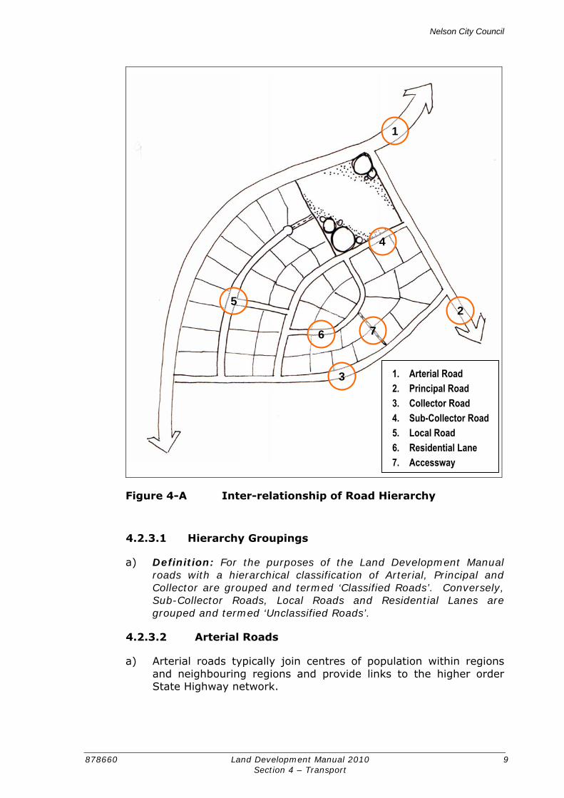
i) The general road hierarchy adopted by the Nelson City Council listed in descending order of importance for through traffic and ascending order of importance for property access is: State Highway, Arterial Road, Principal Road, Collector Road, Sub-Collector Road, Local Road, Residential Lane, Service Lane, Private Way and Accessway. The management of State Highways is the responsibility of the New Zealand Transport Agency.
j) The inter-relationship of the road hierarchy is schematically illustrated in Figure 4-A.
Nelson City Council
878660 Land Development Manual 2010 9 Section 4 – Transport
Figure 4-A Inter-relationship of Road Hierarchy
4.2.3.1 Hierarchy Groupings
a) Definition: For the purposes of the Land Development Manual roads with a hierarchical classification of Arterial, Principal and Collector are grouped and termed ‘Classified Roads’. Conversely, Sub-Collector Roads, Local Roads and Residential Lanes are grouped and termed ‘Unclassified Roads’.
4.2.3.2 Arterial Roads
a) Arterial roads typically join centres of population within regions and neighbouring regions and provide links to the higher order State Highway network.
1. Arterial Road 2. Principal Road 3. Collector Road 4. Sub-Collector Road 5. Local Road 6. Residential Lane 7. Accessway
1
2
3
4
5
6 7
Nelson City Council
878660 Land Development Manual 2010 10 Section 4 – Transport
b) Efficient mobility along the corridor is the principal function of Arterials with access to adjacent land being a subordinate function. Arterial roads are constructed and managed to minimise their local access function.
c) Arterial roads will accommodate a variety of trip lengths.
4.2.3.3 Principal Roads
a) Principal roads typically connect and augment the higher order transport system. As such, these roads often link adjacent suburbs, smaller centres of population and facilitate movement to and access of major attractors and industrial areas.
b) Principal roads have multiple functions of moving people and goods efficiently whilst also providing access to major employment areas and attractors and movement across corridors. The function of mobility should not dominate the management of the corridor to the detriment of access to adjacent land use. Likewise, whilst acknowledging the importance of access to adjacent land use, the effects of traffic generated by adjacent land use shall not detract from the mobility function of the corridor.
c) Principal roads will tend to accommodate short to medium length trips associated with through traffic and local traffic. There is increasing number of trips associated with public transport, walking and cycling.
4.2.3.4 Collector Roads
a) Collector roads distribute traffic between and within local areas and form a link between higher order (Principal and Arterial) roads and lower order (Sub-Collector and Local) roads.
b) The main functions of Collector Roads are to accommodate local traffic and provide access to adjoining property. In the urban area, collector roads usually have predominantly residential frontage and will often contain the bus routes within the neighbourhood.
4.2.3.5 Sub-Collector Roads
a) Sub-Collector Roads distribute the vehicular traffic at a neighbourhood level and form the link between Collector roads and Local roads. A high proportion of traffic on these roads has an origin or destination within the immediate area.
b) In residential areas, Sub-Collector Roads provide high levels of amenity and prioritise access to adjoining property over local traffic movements. Through traffic is not a desired outcome for Sub-Collector Roads.
Nelson City Council
878660 Land Development Manual 2010 11 Section 4 – Transport
4.2.3.6 Local Roads
a) Local Roads have the primary function of providing direct access to properties fronting the road and along which only traffic having an origin or destination there will travel. Pedestrian and local amenity values are predominant.
b) Local Roads provide an environment where pedestrians and cyclists can mix with vehicular traffic, so that the road becomes a useable public space.
4.2.3.7 Residential Lanes
a) Residential Lanes are public roads that provide access for between 7 and 25 residential units.
b) Residential Lanes have the appearance of a Private Way to discourage use by non-local vehicular traffic. Vehicular and pedestrian access to frontage properties is the key function.
4.2.3.8 Service Lanes
c) Service lanes are for the purpose of providing side or rear access for vehicular traffic to land from ‘Classified Roads’ in industrial or commercial areas. When their construction has been completed they may be made into private rights of way.
d) No parking or separate pedestrian facilities are required to be provided.
4.2.3.9 Private Ways
a) Private ways include rights of way, access lots and private driveways and are for providing access over private land to private property.
b) Access to private residential areas can only serve up to 6 potential residential units. If there is potential for more than 6 residential units then a private access is inappropriate and access should be taken from a public road.
4.2.3.10 Accessway
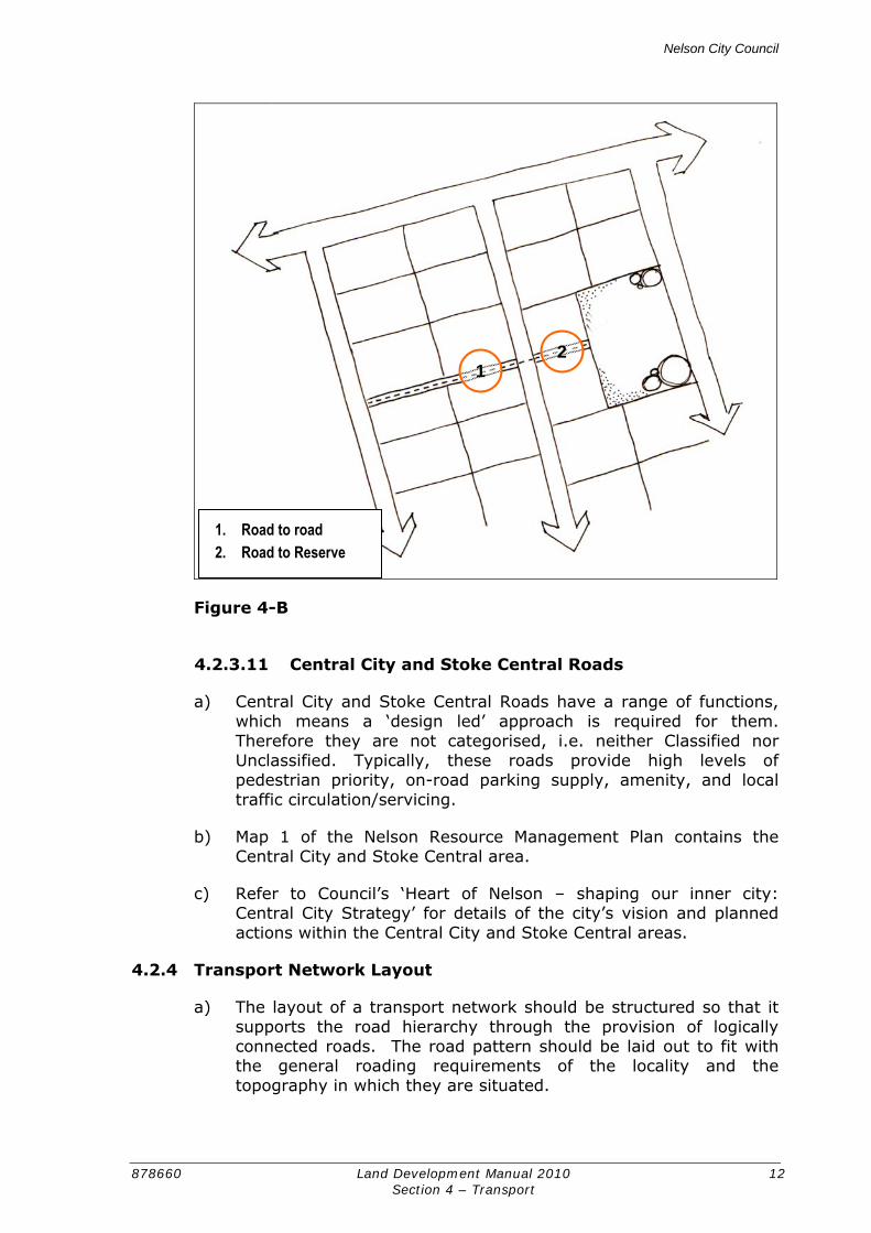
a) An Accessway is a path providing non-motorised access between two or more public roads or between a road and a reserve. This is schematically illustrated in Figure 4-B.
b) An Accessway may service a number of properties along its length.
c) Refer to Section 12 ‘Reserves’ of the Land Development Manual for information related to accessways linking roads to reserves.
Nelson City Council
878660 Land Development Manual 2010 12 Section 4 – Transport
Figure 4-B
4.2.3.11 Central City and Stoke Central Roads
a) Central City and Stoke Central Roads have a range of functions, which means a ‘design led’ approach is required for them. Therefore they are not categorised, i.e. neither Classified nor Unclassified. Typically, these roads provide high levels of pedestrian priority, on-road parking supply, amenity, and local traffic circulation/servicing.
b) Map 1 of the Nelson Resource Management Plan contains the Central City and Stoke Central area.
c) Refer to Council’s ‘Heart of Nelson – shaping our inner city: Central City Strategy’ for details of the city’s vision and planned actions within the Central City and Stoke Central areas.
4.2.4 Transport Network Layout
a) The layout of a transport network should be structured so that it supports the road hierarchy through the provision of logically connected roads. The road pattern should be laid out to fit with the general roading requirements of the locality and the topography in which they are situated.
1 2
1. Road to road 2. Road to Reserve

Nelson City Council
878660 Land Development Manual 2010 13 Section 4 – Transport
b) The transport network should not only facilitate private motor vehicle travel, but also encourage walking, cycling and use of public transport for access to daily activities. This is achieved by providing a permeable and highly-connected network of roads that enables relatively direct trips in and between neighbourhoods and to local activity points.
c) Linkages for pedestrians and cyclists must create an attractive, friendly, connected, safe and accessible environment. These linkages must ensure that people can move about the community freely and safely in areas where there are no road linkages.
d) Large blocks (typically of more than 500m) should be avoided, as this increases trip lengths which ultimately reduces the attractiveness of making trips by active modes.
e) ‘Unclassified Roads’ should be configured to support short trips for local traffic moving in and between neighbourhoods and to spread traffic to keep volumes low.
f) The layout should enhance personal safety and perceptions of safety and minimise potential for crime, vandalism and fear. This can be addressed by providing for roads and urban open spaces to be fronted and overlooked by housing and actively used facilities, especially on routes to and from schools, public transport stops and other routes likely to be used in the hours of darkness. Guidance for achieving development that provides high levels of surveillance to the transport network is provided in Council’s Safer by Design (CPTED) Guidelines.
g) Council may consider variations from these principles where it is satisfied that variations are justified in terms of the following criteria:
1) The design is constrained by topography or existing development and alternative solutions are neither practical nor viable.
2) Where compromises are desirable in order to maintain integrity of the network, to establish effective connections or maintain continuity along a route.
4.2.5 Integration with Adjoining Development
a) New development should connect well to existing, committed, proposed or potential development1 in adjacent areas to facilitate interconnection between new and existing communities. A development with poor links to the surrounding area creates an
1 Potential development means the likely future development within the Services Overlay taking into account the Council’s Strategic City Development Plan and the LTCCP, and the provision of services in a manner that integrates with and does not foreclose this likely future development.

Nelson City Council
878660 Land Development Manual 2010 14 Section 4 – Transport
enclave which encourages movement to and from it by private motor vehicle rather than by other modes.
b) Road connections to existing areas should ensure that outcomes of the connection, such as increased traffic volumes, will be commensurate with the design of those areas. Connectivity between new and existing areas should endeavour to enhance and contribute toward an overall more sustainable community, wherever practical.
c) Where future development on adjoining land is possible, land within the development should be set aside to ensure that future connection is not precluded. The spacing of road connections to adjacent future areas should consider the potential future network requirements of the wider area.
4.2.6 Accessibility
a) Accessibility is the opportunity to travel to a specific activity through the availability of transport and connections. There are three equally important aspects of accessibility:
1) Access to and provided continuously through the network,
2) The quality of mobility on the network,
3) The importance and number of opportunities at various destinations.
b) Accessibility varies with need and often the most vulnerable members of the community are the most transport disadvantaged. Accessibility recognises all modes of transport and subsets of the community that may have less transport choice because of age, physical, financial or other variables.
4.2.6.1 Walkable Neighbourhoods
a) A walkable neighbourhood is characterised by having a high proportion of households within a walkable time of a range of facilities, including but not limited to bus stops, local shops, schools, place of employment, and medical facilities.
b) Walking time is considered to be the best measure for determining walkable catchments, as it takes factors such as waiting times at road crossings into account unlike distance measurements.
c) Creating linkages between new development, local facilities, community infrastructure and the public transport network is fundamental to reducing walking times thereby achieving more sustainable patterns of movement and to reducing people’s reliance on the car.
Nelson City Council
878660 Land Development Manual 2010 15 Section 4 – Transport
d) The provision of an interconnected and highly permeable transport pattern that is promoted throughout this section of the Land Development Manual will assist in the development of walkable neighbourhoods. The other key component in the achievement of a walkable neighbourhood is land use planning. Land use planning governs the location in which particular types of activities may establish. If there is a dearth of facilities at a local level, then the quality, interconnectedness and permeability of the walking network will be of little value.
4.3 ROAD DESIGN
4.3.1 Speed Environment
a) The speed environment can have a huge impact on the actual and perceived safety of roads and therefore have a large influence on a person’s willingness to walk and cycle. High speed environments also detrimentally affect the level of amenity that roads provide compared to roads of a similar character that offer a lower speed environment.
b) It is important that roads are designed to achieve an appropriate speed. The speed environment of roads within a transport network should reflect the function of each road in the context of the environment through which it travels.
c) Local roads in residential areas should be designed to create low speed environments where pedestrians and cyclists can safely and comfortably share road space with motorised traffic.
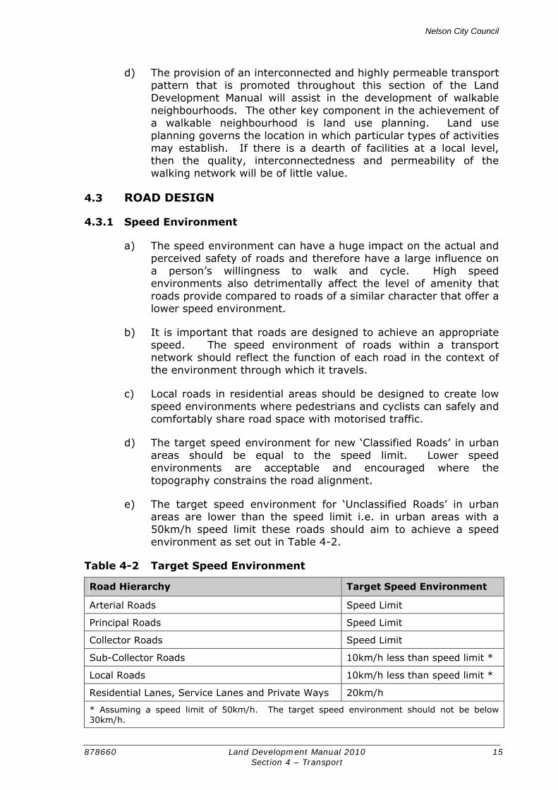
d) The target speed environment for new ‘Classified Roads’ in urban areas should be equal to the speed limit. Lower speed environments are acceptable and encouraged where the topography constrains the road alignment.
e) The target speed environment for ‘Unclassified Roads’ in urban areas are lower than the speed limit i.e. in urban areas with a 50km/h speed limit these roads should aim to achieve a speed environment as set out in Table 4-2.
Table 4-2 Target Speed Environment
Road Hierarchy Target Speed Environment
Arterial Roads Speed Limit
Principal Roads Speed Limit
Collector Roads Speed Limit
Sub-Collector Roads 10km/h less than speed limit *
Local Roads 10km/h less than speed limit *
Residential Lanes, Service Lanes and Private Ways 20km/h
* Assuming a speed limit of 50km/h. The target speed environment should not be below 30km/h.
Nelson City Council
878660 Land Development Manual 2010 16 Section 4 – Transport
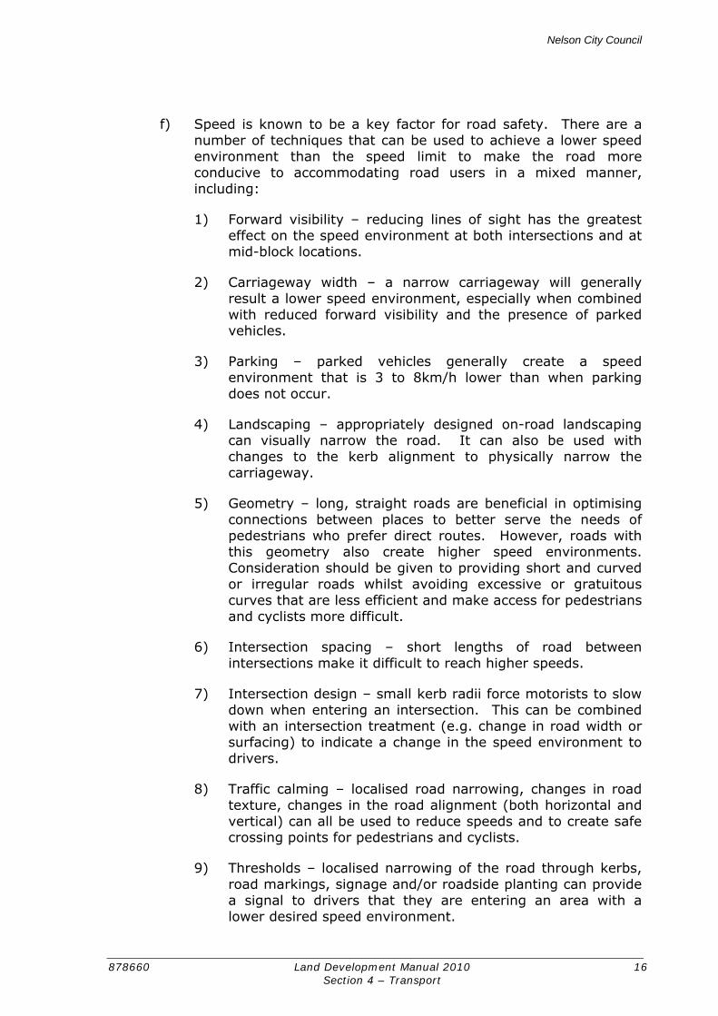
f) Speed is known to be a key factor for road safety. There are a number of techniques that can be used to achieve a lower speed environment than the speed limit to make the road more conducive to accommodating road users in a mixed manner, including:
1) Forward visibility – reducing lines of sight has the greatest effect on the speed environment at both intersections and at mid-block locations.
2) Carriageway width – a narrow carriageway will generally result a lower speed environment, especially when combined with reduced forward visibility and the presence of parked vehicles.
3) Parking – parked vehicles generally create a speed environment that is 3 to 8km/h lower than when parking does not occur.
4) Landscaping – appropriately designed on-road landscaping can visually narrow the road. It can also be used with changes to the kerb alignment to physically narrow the carriageway.
5) Geometry – long, straight roads are beneficial in optimising connections between places to better serve the needs of pedestrians who prefer direct routes. However, roads with this geometry also create higher speed environments. Consideration should be given to providing short and curved or irregular roads whilst avoiding excessive or gratuitous curves that are less efficient and make access for pedestrians and cyclists more difficult.
6) Intersection spacing – short lengths of road between intersections make it difficult to reach higher speeds.
7) Intersection design – small kerb radii force motorists to slow down when entering an intersection. This can be combined with an intersection treatment (e.g. change in road width or surfacing) to indicate a change in the speed environment to drivers.
8) Traffic calming – localised road narrowing, changes in road texture, changes in the road alignment (both horizontal and vertical) can all be used to reduce speeds and to create safe crossing points for pedestrians and cyclists.
9) Thresholds – localised narrowing of the road through kerbs, road markings, signage and/or roadside planting can provide a signal to drivers that they are entering an area with a lower desired speed environment.

Nelson City Council
878660 Land Development Manual 2010 17 Section 4 – Transport
g) The design of all new ‘Unclassified Roads’ must be accompanied by a brief report from an experienced transportation professional identifying those features of the design that will contribute towards achieving the target speed environment.
4.3.2 Intersection Spacing
a) Refer to Figure 4-C
b) Accessibility by walking is enhanced through the provision of more links to create a highly permeable and connected walking network. Long lengths of road between intersections where the surrounding land type would benefit from increased accessibility should be avoided.
c) On ‘Classified Roads’ a balance needs to found between achieving a permeable and connected walking network and the greater importance that is placed on these roads for their through movement function. On these busier roads, closely spaced intersections can:
1) Lead to a confusing and unsafe driving environment that reduces the movement function of the corridor.
2) Deter cyclists, as each intersection increases a cyclist’s exposure to a greater number of potential conflict situations from vehicles turning into and out of side roads.
d) Intersections of ‘Unclassified Roads’ shall provide a minimum centreline to centreline separation of 40m.
e) The minimum centreline to centreline separation of any two roads intersecting a ‘Classified Road’ shall be 110m, increased to 150m where the intersecting roads meet the ‘Classified Road’ in a left-right stagger.
f) Intersections on Principal and Arterial roads that are controlled by traffic signals or roundabouts should have greater separation to balance movement for through traffic with the needs of local traffic and access.
g) Roads that have a speed limit of 80km/h or more should have intersection spacing of no less than 800m.

Nelson City Council
878660 Land Development Manual 2010 18 Section 4 – Transport
Figure 4-C Minimum Intersection Separation by Road Hierarchy
4.3.3 Cross Section
a) The design of new roads or the improvement of existing ones should take into account the road function, the operating objectives, and the type, density and character of surrounding development.
b) The width of the legal road reserve and carriageway should be sufficient to cater for all functions that the road is expected to fulfil, including safe and efficient movement of all users, provision for parking, buffering residents against traffic nuisance, provision
110m min separation 150m min separation (left-right stagger) 40m min separation
Nelson City Council
878660 Land Development Manual 2010 19 Section 4 – Transport
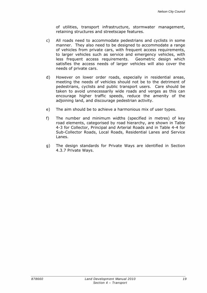
of utilities, transport infrastructure, stormwater management, retaining structures and streetscape features.
c) All roads need to accommodate pedestrians and cyclists in some manner. They also need to be designed to accommodate a range of vehicles from private cars, with frequent access requirements, to larger vehicles such as service and emergency vehicles, with less frequent access requirements. Geometric design which satisfies the access needs of larger vehicles will also cover the needs of private cars.
d) However on lower order roads, especially in residential areas, meeting the needs of vehicles should not be to the detriment of pedestrians, cyclists and public transport users. Care should be taken to avoid unnecessarily wide roads and verges as this can encourage higher traffic speeds, reduce the amenity of the adjoining land, and discourage pedestrian activity.
e) The aim should be to achieve a harmonious mix of user types.
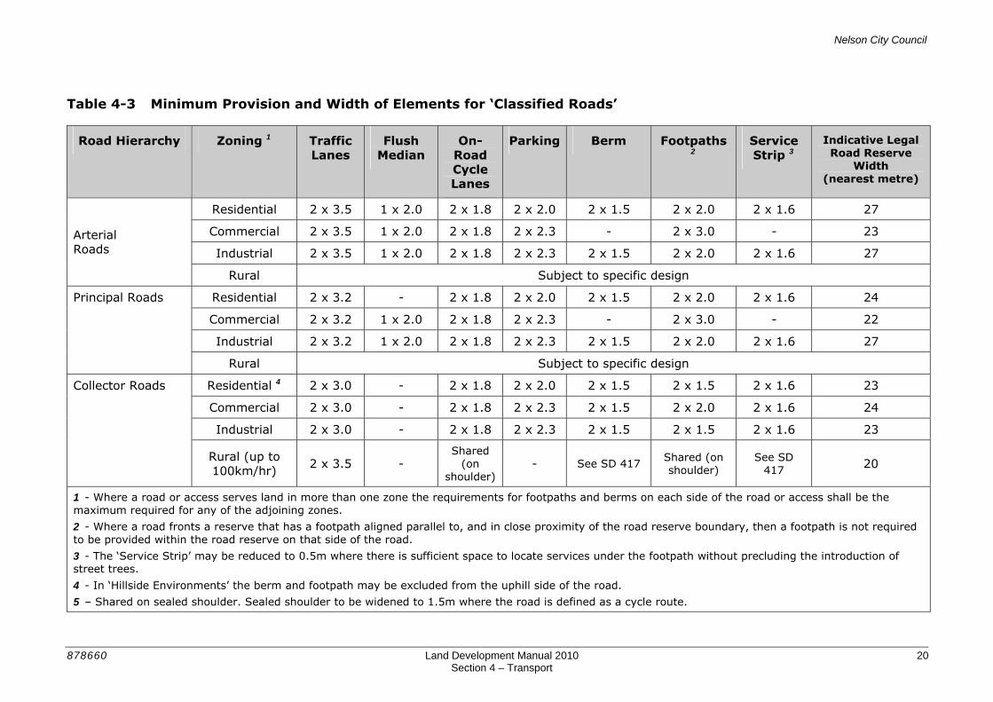
f) The number and minimum widths (specified in metres) of key road elements, categorised by road hierarchy, are shown in Table 4-3 for Collector, Principal and Arterial Roads and in Table 4-4 for Sub-Collector Roads, Local Roads, Residential Lanes and Service Lanes.
g) The design standards for Private Ways are identified in Section 4.3.7 Private Ways.
Nelson City Council
878660 Land Development Manual 2010 20 Section 4 – Transport
Table 4-3 Minimum Provision and Width of Elements for ‘Classified Roads’
Road Hierarchy Zoning 1 Traffic Lanes
Flush Median
On-Road Cycle Lanes
Parking Berm Footpaths 2
Service Strip 3
Indicative Legal Road Reserve
Width (nearest metre)
Residential 2 x 3.5 1 x 2.0 2 x 1.8 2 x 2.0 2 x 1.5 2 x 2.0 2 x 1.6 27
Commercial 2 x 3.5 1 x 2.0 2 x 1.8 2 x 2.3 - 2 x 3.0 - 23
Industrial 2 x 3.5 1 x 2.0 2 x 1.8 2 x 2.3 2 x 1.5 2 x 2.0 2 x 1.6 27
Arterial Roads
Rural Subject to specific design
Residential 2 x 3.2 - 2 x 1.8 2 x 2.0 2 x 1.5 2 x 2.0 2 x 1.6 24
Commercial 2 x 3.2 1 x 2.0 2 x 1.8 2 x 2.3 - 2 x 3.0 - 22
Industrial 2 x 3.2 1 x 2.0 2 x 1.8 2 x 2.3 2 x 1.5 2 x 2.0 2 x 1.6 27
Principal Roads
Rural Subject to specific design
Residential 4 2 x 3.0 - 2 x 1.8 2 x 2.0 2 x 1.5 2 x 1.5 2 x 1.6 23
Commercial 2 x 3.0 - 2 x 1.8 2 x 2.3 2 x 1.5 2 x 2.0 2 x 1.6 24
Industrial 2 x 3.0 - 2 x 1.8 2 x 2.3 2 x 1.5 2 x 1.5 2 x 1.6 23
Collector Roads
Rural (up to 100km/hr)
2 x 3.5 - Shared
(on shoulder)
- See SD 417 Shared (on shoulder)
See SD 417 20
1 - Where a road or access serves land in more than one zone the requirements for footpaths and berms on each side of the road or access shall be the maximum required for any of the adjoining zones.
2 - Where a road fronts a reserve that has a footpath aligned parallel to, and in close proximity of the road reserve boundary, then a footpath is not required to be provided within the road reserve on that side of the road.
3 - The ‘Service Strip’ may be reduced to 0.5m where there is sufficient space to locate services under the footpath without precluding the introduction of street trees.
4 - In ‘Hillside Environments’ the berm and footpath may be excluded from the uphill side of the road.
5 – Shared on sealed shoulder. Sealed shoulder to be widened to 1.5m where the road is defined as a cycle route.

Nelson City Council
878660 Land Development Manual 2010 21 Section 4 – Transport
Table 4-4 Minimum Provision and Width of Elements for ‘Unclassified Roads’
Road Hierarchy Zoning 1 Traffic Lanes
On-Road Cycle Lanes
Parking Berm (Shoulder for Rural)
Footpaths 2 Service Strip 3
Indicative Legal Road Reserve
Width (nearest metre)
Residential 4 1 x 5.6 - 2 x 2.0 2 x 1.5 2 x 1.5 2 x 1.6 18
Commercial 1 x 5.6 - 2 x 2.3 2 x 1.0 2 x 2.0 2 x 1.6 19
Industrial 2 x 3.0 - 2 x 2.3 2 x 1.5 1 x 1.5 2 x 1.6 21 Sub-Collector Roads
Rural (50 to 80km speed environment)
1 x 6.0 Shared (on shoulder) - See SD 417
Shared (on shoulder)
See SD 417 20
Residential 4 1 x 5.2 - 1 x 2.0 2 x 1.5 2 x 1.5 2 x 1.6 16
Residential (< 25 dwellings)
1 x 3.5 5 - 1 x 2.0 2 x 1.5 1 x 1.5 2 x 1.6 13
Local Road
Rural (50km speed environment)
1 x 6.0 Shared (on shoulder) - See SD 417
Shared (on shoulder)
See SD 417 15
Residential Lane Residential (7 to 25 dwellings)
1 x 5.5 6 - Indented
bays 1 x 1.5 1 x 1.5 1 x 0.5 9
1 - Where a road or access serves land in more than one zone the requirements for footpaths and berms on each side of the road or access shall be the maximum required for any of the adjoining zones.
2 - Where a road fronts a reserve that has a footpath aligned parallel to, and in close proximity of the road reserve boundary, then a footpath is not required to be provided within the road reserve on that side of the road.
3 - The ‘Service Strip’ may be reduced to 0.5m where there is sufficient space to locate services under the footpath without precluding the introduction of street trees.
4 - In ‘Hillside Environments’ the berm and footpath may be excluded from the uphill side of the road.
5 – Passing bays shall be provided at least every 50m. Mutual driveways may be used as passing bays, see 6 below.
6 – Required for the first 12m from any intersection with higher order roads i.e. Local Roads and above. Thereafter, the traffic lane width may be narrowed to 3.5m. Mutual driveways shall be provided at adjoining lot boundaries (12.0m total width) to function as passing bays at least every 50m. The minimum dimensions for a passing bay are set out in section 4.3.7.g).
Nelson City Council
878660 Land Development Manual 2010 22 Section 4 – Transport
h) The indicative Legal Road widths assume that all elements are provided to the minimum width and located alongside one another. The indicative Legal Road width will vary depending on the ultimate design of the road. Some of the more common factors that will affect the indicative Legal Road widths are:
1) On roads in residential areas parking may be provided as indented parking bays within the berm area. This will result in a narrower overall Legal Road width.
2) Where services are located under the footpath (refer Section 4.3.19 ‘Utilities’) the Service Strip may be reduced to 0.5m.
3) Some elements may not be mandatory in ‘Hillside Environments’ to minimise the adverse environmental and amenity effects created by excessive earthworks.
4) The use of alternative stormwater methods such as swales, which are likely to require additional berm width.
5) Wider legal road widths may be required to accommodate road retaining structures.
i) The planning and incorporation of bus routes into a new subdivision should be included as part of the subdivision application. Roads that accommodate, or may accommodate a future bus route should be designed in accordance with the requirements specified in Section 4.3.11 Public Transport.
j) Council may consider variations from these indicative cross sections where alternative cross-sections and supporting analysis is provided.
4.3.3.1 Shoulders
a) The shoulder is that portion of the carriageway beyond the traffic lanes, adjacent to, and flush with the surface of the pavement. Its purpose is to accommodate stopped vehicles, provide lateral support to the road pavement layers and, if sealed, offer improved conditions for cyclists.
b) The shoulder width is measured from the edge of the traffic lane (delineated with a marked edge line) to the berm.
c) All roadside furniture, including landscaping should be located outside the shoulder wherever possible.
d) The minimum width of shoulders on non-urban roads without kerb and channel are specified in Table 4-5.

Nelson City Council
878660 Land Development Manual 2010 23 Section 4 – Transport
Table 4-5 Minimum Width of Shoulders
Minimum Shoulder Width (m)
Up to 50km design speed
50 – 80 km/hr design speed
80 – 100 km/hr design speed
Road Hierarchy
Formed Width
Sealed Width
Formed and Sealed width
Formed and Sealed width
Collector Roads 2.0 1.0 2.0
Sub-Collector Roads 1.5 0.5 2.0
Local Roads 1.0 0.5 2.0
Sealed path separated by verge to specific design
Private Ways 0.5 0.5 1 1 – Plus, passing bays every 50m
4.3.3.2 Medians
a) A raised traffic island is a useful traffic management device to channel traffic or provide a refuge for pedestrians crossing the road.
b) Flush medians are most commonly used on ‘Classified Roads’ where property access needs to be maintained but where there are safety benefits in removing turning vehicles from the through traffic stream, and in providing pedestrians with an opportunity to cross the road in two stages.
c) Flush medians are intended primarily for urban speed environment conditions i.e. a speed limit of 70km/h or less.
d) Flush medians may be appropriate when:
1) Right turning traffic is interfering with through traffic causing accidents or problems with delays,
2) Pedestrians are having difficulty crossing a busy road,
3) The carriageway is excessively wide, or
4) Property access needs to be maintained and any of the above conditions exist.
e) Flush medians are not recommended for use on high speed roads (80km/h +) due to difficulties in controlling overtaking vehicles in these environments.
f) Flush medians shall be designed with a width that is between 2.0m and 2.5m.
g) Flush medians that accommodate a pedestrian island must be at least 2.4m wide. For marking details refer to the NZTA Manual of Traffic Signs and Markings (MOTSAM) Part II – Markings.
Nelson City Council
878660 Land Development Manual 2010 24 Section 4 – Transport
4.3.4 Cul-de-sacs
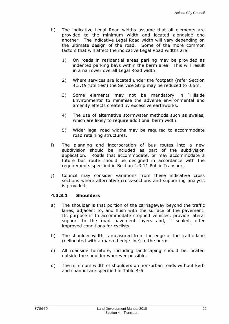
a) A cul-de-sac is a ‘no exit’ street for motor vehicles. The extent of a cul-de-sac is defined from the last intersection that provides driver choice to multiple destinations within the wider transport network i.e. a through road. The roading layout presented in Figure 4-DA shows a layout where the entire road network off the main road would be classified as a long cul-de-sac.
Figure 4-D A Extent of Cul-de-sac
b) The roading layout presented in Figure 4-DB shows how a connected road network can reduce the prevalence of cul-de-sacs.
Figure 4-D B Extent of Cul-de-sac

Nelson City Council
878660 Land Development Manual 2010 25 Section 4 – Transport
c) Cul-de-sacs are normally introduced into developments to develop awkward sites and to maximise lot yield by servicing land that could not readily be serviced by a connecting through road. Cul-de-sacs can also provide a pleasant residential environment in which to live because of low traffic volumes.
d) However, there are also a number of potential disadvantages of cul-de-sacs. These are particularly evident if cul-de-sacs are used excessively within a residential development. The potential issues include:
1) An impermeable road network that reduces transport accessibility and the opportunity to access community facilities,
2) The discouragement of walking and cycling leading to increased reliance on private motor vehicle travel,
3) Poor public transport route structures and accessibility, and
4) Lost opportunity to link with future roads.
e) A balanced approach to the use of cul-de-sacs is required.
f) A cul-de-sac shall be no longer than 150m and serve no more than 25 potential residential dwellings, except in ‘Hillside Environments’ where the topography may preclude the interconnection of roads. In ‘Hillside Environments’ a cul-de-sac may have a length of up to 400m while serving no more than 40 potential residential dwellings.
g) No more than 15 per cent of lots in any development, except in ‘Hillside Environments’, shall have frontage to a cul-de-sac.
h) Cul-de-sacs must be designed so that pedestrians and cyclists can have through access, especially where that access would link to local facilities, other roads or recreation opportunities, as illustrated in Figure 4-K.
i) Cul-de-sacs that may function as future through roads must be designed to the standard of the future function.
4.3.4.1 Turning Head
a) A turning facility shall be provided at the end of all cul-de-sacs.
b) Turning areas require a lot of road space and they are generally wasteful in land terms. The road area for manoeuvring should be kept to a minimum and opportunities taken to incorporate design features such as landscaping, street furniture and central parking spaces to make these areas attractive focal points.
Nelson City Council
878660 Land Development Manual 2010 26 Section 4 – Transport
c) The minimum radius of the turning circle of a cul-de-sac shall be 7m in residential areas, 11m in commercial and 12m in industrial areas, as per SD 419 ‘Cul-de-sac Turning Circles’.
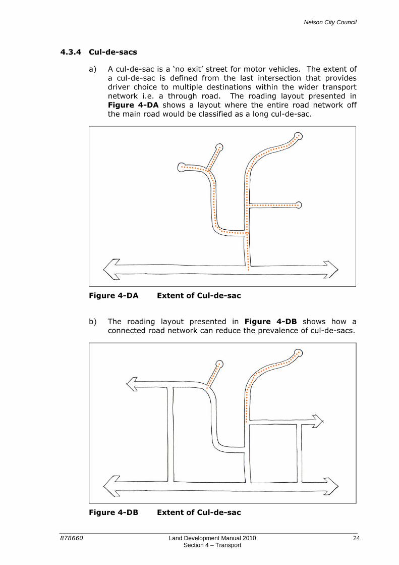
d) For residential cul-de-sacs and Residential Lanes in ‘Hillside Environments’ the turning area may be a ‘Hammerhead’ or ‘Fishtail’ layout, as indicated in Figure 4-E provided it is sufficient to allow an 8m medium rigid truck with 10m turning radius to undertake a three point turn.
Figure 4-E Hammerhead and Fishtail Turning Head Arrangements
e) Where a road is developed in stages a turning area shall be provided at the end of the construction or within at least 20m of the end of the road. The pavement shall be formed to the same standard as the road and permanently surfaced to provide an area sufficient to allow a 3-point turn by an 8m medium rigid truck with 10m turning radius.
4.3.5 Residential Lanes
a) Residential Lanes are public roads that serve between 7 and 25 residential units.
b) A road shall only be designed and constructed as a Residential Lane with the prior approval of Council. Council will consider allowing a Residential Lane where:
1) The natural or physical constraints inhibits or precludes construction of an access road to a Local Road standard; or
2) The lane would only serve dwellings on one side i.e. the other side borders a riparian strip or other land accessed from elsewhere; or
3) Vehicular access is required to the rear of residential properties that have frontage, but no vehicular access to a ‘Classified Road’; or
4) A Residential Lane is the most efficient form of access for a residential intensification / infill development.

Nelson City Council
878660 Land Development Manual 2010 27 Section 4 – Transport
c) Residential Lanes that have only one intersection with higher order roads must be designed with a turning area at the head that is sufficient to accommodate a 3-point turn of a 90th percentile 2-axle truck.
d) The design of Residential Lanes shall be consistent with the minimum standards shown in Table 4-4.
4.3.6 Service Lanes
a) Service lanes are for the purpose of providing side or rear access for vehicular traffic to land from ‘Classified Roads’ in industrial or commercial areas.
b) Service Lanes must have at least two intersections with higher order roads i.e. Service Lanes must not be designed as a cul-de-sac.
c) A Service Lane must have a minimum carriageway width of 4m. Separate parking or pedestrian facilities are not required to be provided.
4.3.7 Private Ways
a) Private ways are not directly a Council responsibility, but their safe and efficient functioning and ongoing maintenance can have an effect on Council’s transport network.
b) Where necessary, private ways can be used to create a more private, secluded environment and, because they minimise the amount of hard surface, can look very attractive, if carefully managed.
c) The use of shared turning space in a private way allows more semi-public space to be provided between sections, creating a sense of openness. Furthermore, it reduces the need for on-site turning which takes up space on the section and requires large areas of hard surfacing.
d) Private ways must:
1) Provide good passive surveillance into, along and through lanes.
2) Only serve up to 6 potential residential units. Any access that serves more than 6 potential residential units must be designed as a Local Road. In certain circumstances, Council may permit the access to be designed and constructed as a Residential Lane, subject to satisfying the criteria set out in Section 4.3.5 ‘Residential Lanes’.

Nelson City Council
878660 Land Development Manual 2010 28 Section 4 – Transport
3) Be designed in accordance with the widths specified in Table 4-6 so as not to be confused with public roads.
4) Not create a more direct through-route alternative for vehicles, cycles or pedestrians than the adjoining road network.
5) Provide adequate sightlines for both pedestrians and cars at intersections without excessive truncations on adjoining properties that are required at intersections with public roads.
6) Provide for utility services.
Table 4-6 Private Way Design
Potential Number of Units
Carriageway Width
Legal Reserve Width
Footpath
Residential 1 to 6 2.75 m 4.5 m No
Rural 1 to 6 2.5 m 6.0 m No
Commercial and industrial
See NZS 4404
e) In situations where more than one residential unit uses a private way and where a shared section of private way is more than 50m long a passing bay shall be provided at least once every 50m.
f) Passing bays shall be positioned at regular intervals and achieve a clear line of sight from the passing bay to the start and end of the private way or to the next passing bay.
g) Any passing bay shall be constructed to a minimum width of 5.5m and have a minimum length of 6.0m with a 4.0m long taper at each end.
h) Private ways must have a permanent surface for a minimum distance of 5m into the property from the legal boundary of the road. Private ways serving more than one unit must have a permanent surface throughout the length of the right of way
i) When designing private ways, the long term maintenance costs for the residents must be balanced against the benefits of providing access through a vested road. Irrespective, design and construction standards, including drainage, for private ways must comply with the requirements for an equivalent construction within legal road, including the 50-year design life.
Nelson City Council
878660 Land Development Manual 2010 29 Section 4 – Transport
4.3.8 Road Geometry
4.3.8.1 Gradients
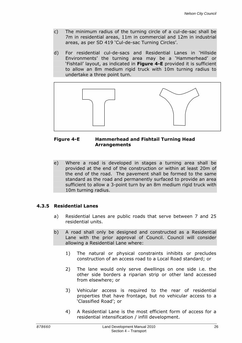
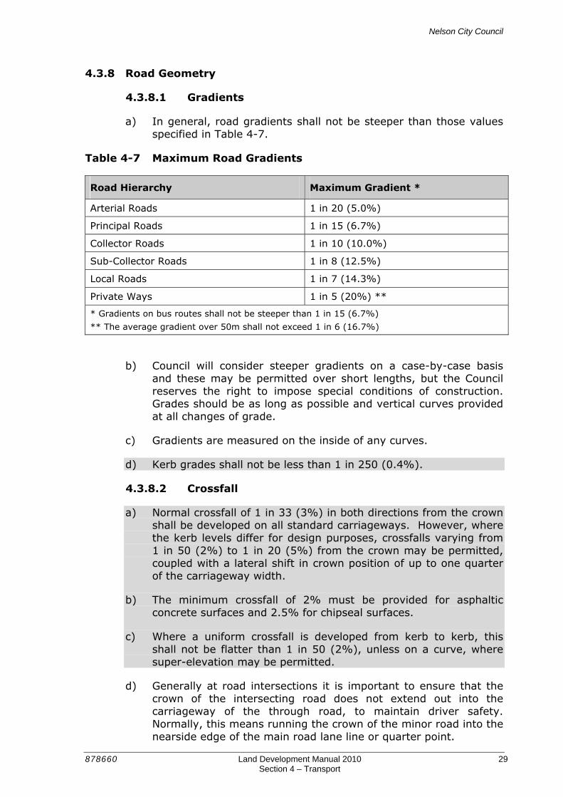
a) In general, road gradients shall not be steeper than those values specified in Table 4-7.
Table 4-7 Maximum Road Gradients
Road Hierarchy Maximum Gradient *
Arterial Roads 1 in 20 (5.0%)
Principal Roads 1 in 15 (6.7%)
Collector Roads 1 in 10 (10.0%)
Sub-Collector Roads 1 in 8 (12.5%)
Local Roads 1 in 7 (14.3%)
Private Ways 1 in 5 (20%) **
* Gradients on bus routes shall not be steeper than 1 in 15 (6.7%)
** The average gradient over 50m shall not exceed 1 in 6 (16.7%)
b) Council will consider steeper gradients on a case-by-case basis and these may be permitted over short lengths, but the Council reserves the right to impose special conditions of construction. Grades should be as long as possible and vertical curves provided at all changes of grade.
c) Gradients are measured on the inside of any curves.
d) Kerb grades shall not be less than 1 in 250 (0.4%).
4.3.8.2 Crossfall
a) Normal crossfall of 1 in 33 (3%) in both directions from the crown shall be developed on all standard carriageways. However, where the kerb levels differ for design purposes, crossfalls varying from 1 in 50 (2%) to 1 in 20 (5%) from the crown may be permitted, coupled with a lateral shift in crown position of up to one quarter of the carriageway width.
b) The minimum crossfall of 2% must be provided for asphaltic concrete surfaces and 2.5% for chipseal surfaces.
c) Where a uniform crossfall is developed from kerb to kerb, this shall not be flatter than 1 in 50 (2%), unless on a curve, where super-elevation may be permitted.
d) Generally at road intersections it is important to ensure that the crown of the intersecting road does not extend out into the carriageway of the through road, to maintain driver safety. Normally, this means running the crown of the minor road into the nearside edge of the main road lane line or quarter point.

Nelson City Council
878660 Land Development Manual 2010 30 Section 4 – Transport
4.3.8.3 Super-Elevation
a) Super-elevation is not required in areas with a 50km/h speed limit.
b) On roads where the speed limit is over 50km/h, specific design of super-elevation is required. Where super-elevation is required, the maximum value on ‘Unclassified Roads’ shall be 5%.
c) In ‘Hillside Environments’ super-elevation may be employed where it suits boundary levels up to the allowable design maximum crossfall.
4.3.8.4 Kerblines
a) Generally, kerbs shall be at the same level on both sides of the road. However, in some circumstances, the left and right hand kerb lines may be better graded individually in conjunction with centre line levels, footpath levels and boundary levels. Under such circumstances, at a given cross section, the left and right hand kerbs must only differ from each other in level within the following tolerance:
Maximum difference in kerb level = 120mm + 15mm/m for roads with a carriageway wider than 7.0m.
4.3.8.5 Stormwater Drainage
a) All stormwater from the carriageway and footpaths on roads and private ways shall be collected by an approved stormwater system. Refer to Section 5 Stormwater of the Land Development Manual for design and construction guidance on stormwater matters.
4.3.8.6 Horizontal Curves
a) Horizontal curves in 50 km/hr zones that are circular must have a minimum centreline radius of 80m for roads in industrial areas and 40m for roads in residential areas. For Local Roads in residential areas and Residential Lanes, horizontal curves may be reduced to a 25m circular radius with associated widening to the inner edge to enable truck and trailer combinations to safely negotiate curves in one pass.
b) ‘Classified Roads’ that have or may have a speed limit of more than 50km/h in the future require spiral transition curves consistent with a specified speed value.
c) Reverse curves shall be avoided where possible. If they are necessary, balance and separate them by a sufficient length of straight road to allow for a satisfactory rate of super-elevation reversal (where the design speed is greater than 50km/h).

Nelson City Council
878660 Land Development Manual 2010 31 Section 4 – Transport
d) Curves in the same direction in close proximity must be compounded to avoid “broken back” effects.
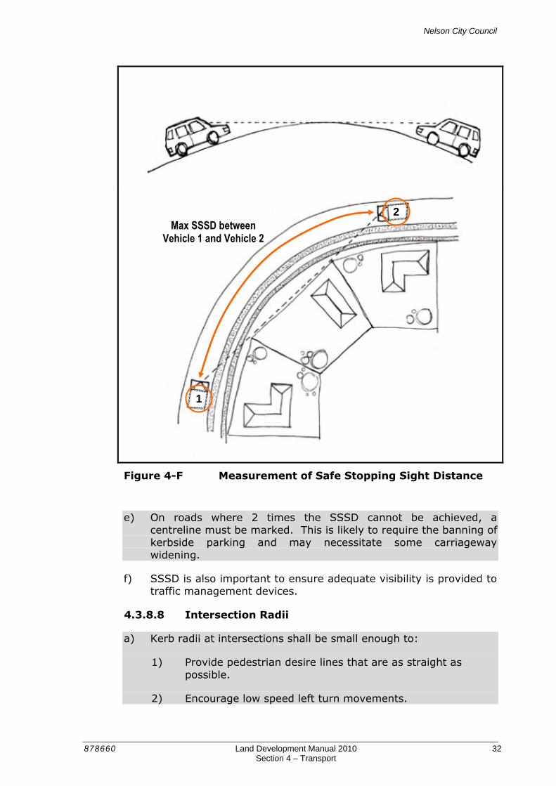
4.3.8.7 Sight Distance
a) Safe Stopping Sight Distance (SSSD) is distance required for a vehicle to safely stop between the time when the driver receives a stimulus signifying a need to stop and the time the vehicle comes to rest.
b) Table 4-8 shows acceptable SSSD for various design speeds in urban areas.
Table 4-8 Safe Stopping Sight Distance (SSSD)
Design Speed Safe Stopping Sight Distance (m) *
≤ 30 km/h 25
40 km/h 35
50 km/h 45
60 km/h 65
* As required on level grade. Correction factors are to be applied on non-level roads.
c) SSSD is important in the design of ‘Unclassified Roads’ (roads that
generally do not require a centreline to be marked) to ensure that sufficient visibility is provided between opposing vehicles on narrow carriageways to see each other and stop.
d) SSSD is measured both in relation to vertical and horizontal curvature as illustrated in Figure 4-F.
Nelson City Council
878660 Land Development Manual 2010 32 Section 4 – Transport
Figure 4-F Measurement of Safe Stopping Sight Distance
e) On roads where 2 times the SSSD cannot be achieved, a centreline must be marked. This is likely to require the banning of kerbside parking and may necessitate some carriageway widening.
f) SSSD is also important to ensure adequate visibility is provided to traffic management devices.
4.3.8.8 Intersection Radii
a) Kerb radii at intersections shall be small enough to:
1) Provide pedestrian desire lines that are as straight as possible.
2) Encourage low speed left turn movements.
1
2 Max SSSD between
Vehicle 1 and Vehicle 2
Nelson City Council
878660 Land Development Manual 2010 33 Section 4 – Transport
3) Enable an RTS-14 compliant tactile paver layout to be provided.
b) Kerb radii at intersections shall be large enough to accommodate the turning requirements of the design vehicle as follows:
1) For turns at intersections where both roads are ‘Classified Roads’ the design semi-trailer with turning path radius of 12.5m, without crossing the centreline of the road being entered.
2) For turns between a ‘Classified Road’ and a ‘Unclassified Road’ the design semi-trainer with turning path radius of 12.5m, using any part of the ‘Unclassified Road’ carriageway, and the design large rigid truck with turning path radius of 12.5m using the correct side of the ‘Unclassified Road’ carriageway.
3) For turns at intersections where both roads are ‘Unclassified Roads’, the design medium rigid truck with turning path radius of 10m, using any part of the carriageway. However, Council may require intersections to be designed for a larger vehicle if larger vehicle movements are expected.
4) For turns between all public roads, the 85th percentile design car with a minimum turning path radius of 5.8m, using the correct side of the carriageway only.
c) For any of these cases, the design vehicle must not cross the road centreline of any ‘Classified Road’ when turning left into or out of the intersecting road.
d) Kerb radii shall not be less than 3.0m.
e) At signalised intersections it is better to minimise the kerb radii and set the limit line of the rightmost lane back from other lanes to facilitate the turning requirements of larger vehicles in preference to providing a larger kerb radii.
f) Consideration should always be given to narrowing the width of the carriageway at intersections with kerb extensions to keep pedestrian crossing distances to a minimum and control turning vehicle speeds while allowing for safe passage by cyclists, as shown in Figure 4-G.
g) A radii of 5m is typically required at kerb extensions to facilitate mechanical street cleaning.

Nelson City Council
878660 Land Development Manual 2010 34 Section 4 – Transport
Figure 4-G Example of Kerb Extensions at an Intersection
4.3.9 Batters
a) No batter in either cutting or filling shall be steeper than 1 in 1.5 (67%) without the approval of Council, and in certain cases, a soils report will be required to establish the safe batter slope and specific low maintenance landscaping/vegetation will be required, other than grass. See 4.3.9g) below.
b) In flat terrain, the bottom edge of the fill batter or the top of a cut batter shall start at least 600mm on the roadside of the property boundary. In ‘Hillside Environments’, the toe of the cut batter may start 1m from the kerb or back of footpath, and the top of the fill batters may start 1m from the kerb or back of footpath (see SD 21 /305, Sheet 4).
c) All new cut faces must be retained or stabilised with vegetation. Slopes steeper than 1 in 2 (45%) require a geotechnical assessment to determine if retaining is required.
d) Where conditions indicate, retaining walls or benching may be required. Where retaining walls are required, certified design plans for any such walls shall be submitted and a building consent obtained.
e) Stabilised faces or retaining structures that support private assets or property must be located outside of the legal road reserve.
f) Structures supporting the road must be located within the legal road reserve. This may require adjustment of the legal road boundary. See also, Section 3.4.5.
Nelson City Council
878660 Land Development Manual 2010 35 Section 4 – Transport
g) Where a batter is not required to cater for foot traffic, grassed batters are permitted, to a maximum of 1 in 4 (25%) to ensure they are mowable.
4.3.10 Hillside Construction
a) Definition: For the purposes of the Land Development Manual, a road is considered to be in a hillside environment where the road is formed on ground that has an average slope of greater than 10 degrees.
b) Roads should generally follow the natural contours of the land and should not be placed perpendicular to contour lines unless absolutely unavoidable. Curvilinear road alignments are preferred to influence a lower speed environment.
c) Cut and fill shall be kept to a minimum to avoid earthworks altering the natural land form and avoiding removal of natural features, i.e. sediment and vegetation.
d) Where the road is or will be constructed on a slope, this can affect the ability to provide all the required elements of a streetscape and therefore impact on the achievable widths for some or all of those elements.
e) A balance should be achieved between complying with design standards and minimising the adverse effects that excessive earthworks can create such as visual pollution and high construction and maintenance costs. Council may consider deviations from the design guidance provided in the Land Development Manual for sites that are topographically constrained or to minimise the effects of earthworks. The type of deviations that Council may consider for hillside construction include:
1) Providing narrower legal road widths. Wider widths may be impractical as it may be impossible to utilise more than a certain width due to crossfall restrictions. Property access may also be compromised if wide roads require high cuts or retaining walls.
2) Provide for on-road parking in parking bays as an alternative to continuous kerbside parking lanes.
3) Provide a lesser standard of elements, such as constructing only one footpath. Where only one footpath is provided it should generally be on the downhill side of the road.
4) Locate pedestrian and cycle facilities separately from the carriageway.

Nelson City Council
878660 Land Development Manual 2010 36 Section 4 – Transport
4.3.11 Public Transport Routes
a) The development of urban land and design of transport networks must attempt to maximise the convenient access of public transport.
b) Bus routes are typically located on ‘Classified Roads’ and in residential neighbourhoods these may extend onto Sub-Collector and Local Roads to maximise the residential catchment. Bus routes are chosen to achieve a highly accessible residential catchment that provides access to high transport intensity land uses (such as schools, tertiary institutions, hospitals, medical facilities, shopping areas, retirement villages and community facilities).
c) Residential development should be designed to maximise the number of sites within a 5 minute walk (approximately 400m) of a bus stop. Residential development that does not have a frontage on the bus route shall be provided with convenient walking access to that route.
d) An efficient bus service may be assisted by:
1) Locating bus stops conveniently to maximise the walkable catchment while balancing spacing with bus journey times;
2) Locating bus stops on the downstream side of intersections;
3) Ensuring bus stops and most access routes to them will have some surveillance from surrounding development; and
4) Ensuring traffic management devices are bus friendly.
e) Roads that accommodate, or may accommodate a future bus route shall be constructed to ensure two-way traffic flow is maintained at all times. Intersections shall be designed to accommodate the turning requirements of the bus without crossing the centreline of the road being entered (or exited from for left turns).
f) The gradient of roads with a bus route shall be suitable for the bus servicing the route.
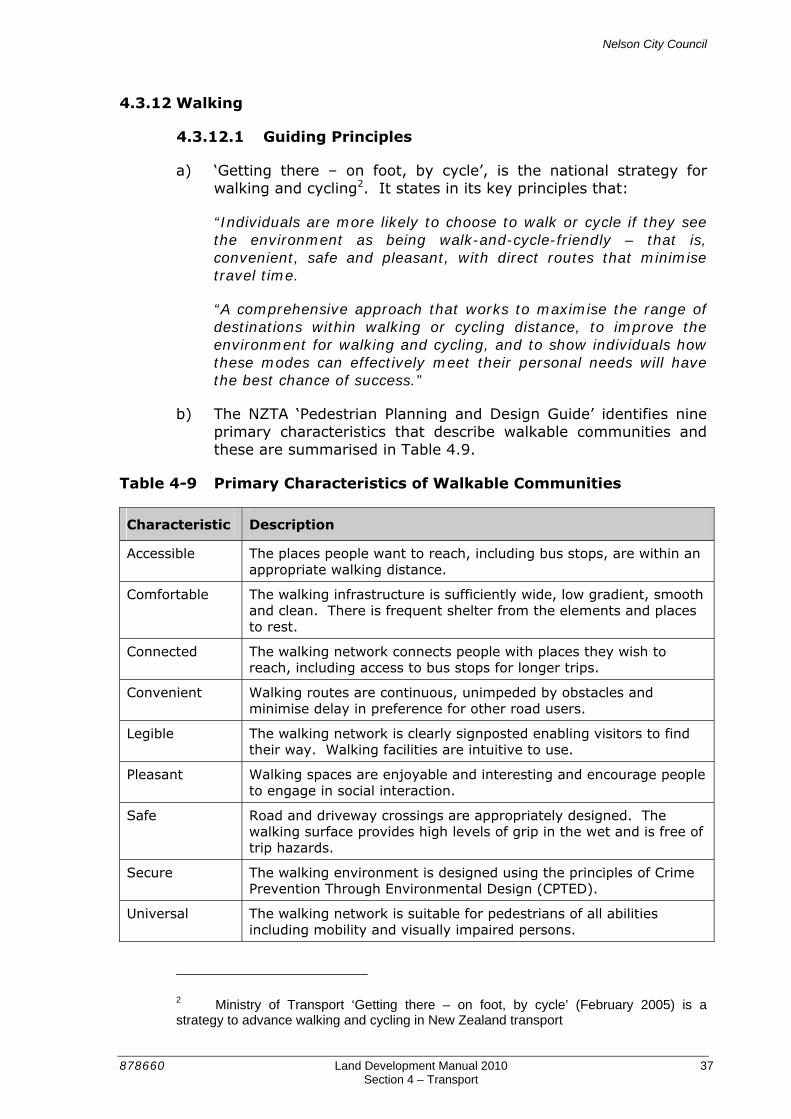
Nelson City Council
878660 Land Development Manual 2010 37 Section 4 – Transport
4.3.12 Walking
4.3.12.1 Guiding Principles
a) ‘Getting there – on foot, by cycle’, is the national strategy for walking and cycling2. It states in its key principles that:
“Individuals are more likely to choose to walk or cycle if they see the environment as being walk-and-cycle-friendly – that is, convenient, safe and pleasant, with direct routes that minimise travel time.
“A comprehensive approach that works to maximise the range of destinations within walking or cycling distance, to improve the environment for walking and cycling, and to show individuals how these modes can effectively meet their personal needs will have the best chance of success.”
b) The NZTA ‘Pedestrian Planning and Design Guide’ identifies nine primary characteristics that describe walkable communities and these are summarised in Table 4.9.
Table 4-9 Primary Characteristics of Walkable Communities
Characteristic Description
Accessible The places people want to reach, including bus stops, are within an appropriate walking distance.
Comfortable The walking infrastructure is sufficiently wide, low gradient, smooth and clean. There is frequent shelter from the elements and places to rest.
Connected The walking network connects people with places they wish to reach, including access to bus stops for longer trips.
Convenient Walking routes are continuous, unimpeded by obstacles and minimise delay in preference for other road users.
Legible The walking network is clearly signposted enabling visitors to find their way. Walking facilities are intuitive to use.
Pleasant Walking spaces are enjoyable and interesting and encourage people to engage in social interaction.
Safe Road and driveway crossings are appropriately designed. The walking surface provides high levels of grip in the wet and is free of trip hazards.
Secure The walking environment is designed using the principles of Crime Prevention Through Environmental Design (CPTED).
Universal The walking network is suitable for pedestrians of all abilities including mobility and visually impaired persons.
2 Ministry of Transport ‘Getting there – on foot, by cycle’ (February 2005) is a strategy to advance walking and cycling in New Zealand transport
Nelson City Council
878660 Land Development Manual 2010 38 Section 4 – Transport
4.3.12.2 Crime Prevention Through Environmental Design (CPTED)
a) The design of buildings and the arrangement of streets, parks and other outdoor spaces can influence the opportunity for crime and the level of fear of crime.
b) Careful environmental design can help make places less susceptible to crime and enable people to feel more comfortable outdoors.
c) To ensure that crime prevention is properly taken into account, it is important that the way in which permeability is provided is given careful consideration. A highly permeable and connected transport network is conducive to walking and cycling, but can lead to problems of anti-social behaviour if it is only achieved by providing routes that are poorly overlooked, such as enclosed walking/cycling links.
d) Methods that should be considered in the design of transport networks to reduce the likelihood of crime and enhance perceived personal security are:
1) Providing clear sightlines – ensure pedestrians are able to see and be seen clearly in the surrounding area. Avoid sudden corners, blind bends and recessed areas along walking/cycling links and ensuring that planting does not grow to reduce passive surveillance or provide hiding places for offenders.
2) Providing good quality lighting – choose lighting that illuminates pedestrian areas as well as roads and ensure it is consistently placed to not conflict with planting or create large areas of shadow.
3) Providing environments that encourage high level of social interaction – design walking/cycling links to ensure that they are well used to prevent them becoming isolated and unsafe. Refer Section 4.2.2.1 ‘Place’ for further guidance.
4) Providing highly maintained environments – places which are run down and neglected tend to feel less safe. Regular maintenance of buildings and garden areas along with the removal of graffiti and litter all help to make people feel more comfortable in outdoor spaces.
5) Avoiding potential entrapment situations – providing alternative walking/cycling routes so people do not have to take unsafe routes.
Nelson City Council
878660 Land Development Manual 2010 39 Section 4 – Transport
4.3.12.3 Footpath Width
a) Table 4-3 and Table 4-4 specify the number and width of footpaths that are to be provided in various planning zones.
b) Notwithstanding the widths specified in those tables, the minimum footpath width along any road with frontage to a school shall be 2m.
c) The widths specified in Table 4-3 and Table 4-4 are ‘Through Route’ widths that must be free of all obstructions such as vegetation, light standards, signs, utility furniture, bollards etc. Where objects are located adjacent to a footpath a pedestrian will tend to ‘shy away’ from those objects. In order to ensure ‘Through Route’ widths are maintained, the minimum footpath width shall be increased by 150mm where such an object is present on one side and by 300mm where objects are present on both sides.
d) Where any footpath is located directly against the property boundary it must have a minimum width of 1.65m. Where a footpath is located against a kerb, the width of the footpath excludes the top of the kerb.
e) Where topography or existing features preclude providing the minimum widths, discuss options with Council.
f) Refer to Figure 4-H

Nelson City Council
878660 Land Development Manual 2010 40 Section 4 – Transport
Figure 4-H Minimum Footpath Widths
4.3.12.4 Footpath Location
a) In residential areas, footpaths shall be separated from the carriageway by a berm. Footpaths may only be located abutting kerbs in ‘Hillside Environments’, where the provision of additional road width to accommodate a berm will result in excessive earthworks.
1.50m
1.65m
1.80m
1.50m + 0.15m for top of kerb
Footpath between grassed berms
Footpath adjacent to landscaping (one side)
Footpath adjacent to kerb
Footpath adjacent to landscaping (both sides)

Nelson City Council
878660 Land Development Manual 2010 41 Section 4 – Transport
b) In commercial areas, footpaths should generally be located against the kerb and typically they will extend from kerb to property boundary.
c) In other areas, the location of the footpath should be selected by taking into account pedestrian amenity, sun and shade, road lighting, postal deliveries and likely use patterns.
4.3.12.5 Design of Footpaths
a) Footpaths are designed to accommodate the movement of pedestrians. Pedestrians are a diverse user group and include people of all ages, sizes and abilities. Accordingly, the design of footpaths needs to satisfy a wide range of user requirements. Generally, this can be achieved by designing footpaths to accommodate the needs of children and disabled people.
b) The design of footpaths should be in accordance with the requirements of the NZTA Pedestrian Planning and Design Guide.
c) For convenience, critical aspects of footpath design specified in this guide that must be adhered to are presented in Table 4-10. Where a conflict exists between any design criteria specified in the NZTA Pedestrian Planning and Design Guide and this Land Development Manual, the Land Development Manual takes preference at the discretion of the Council.
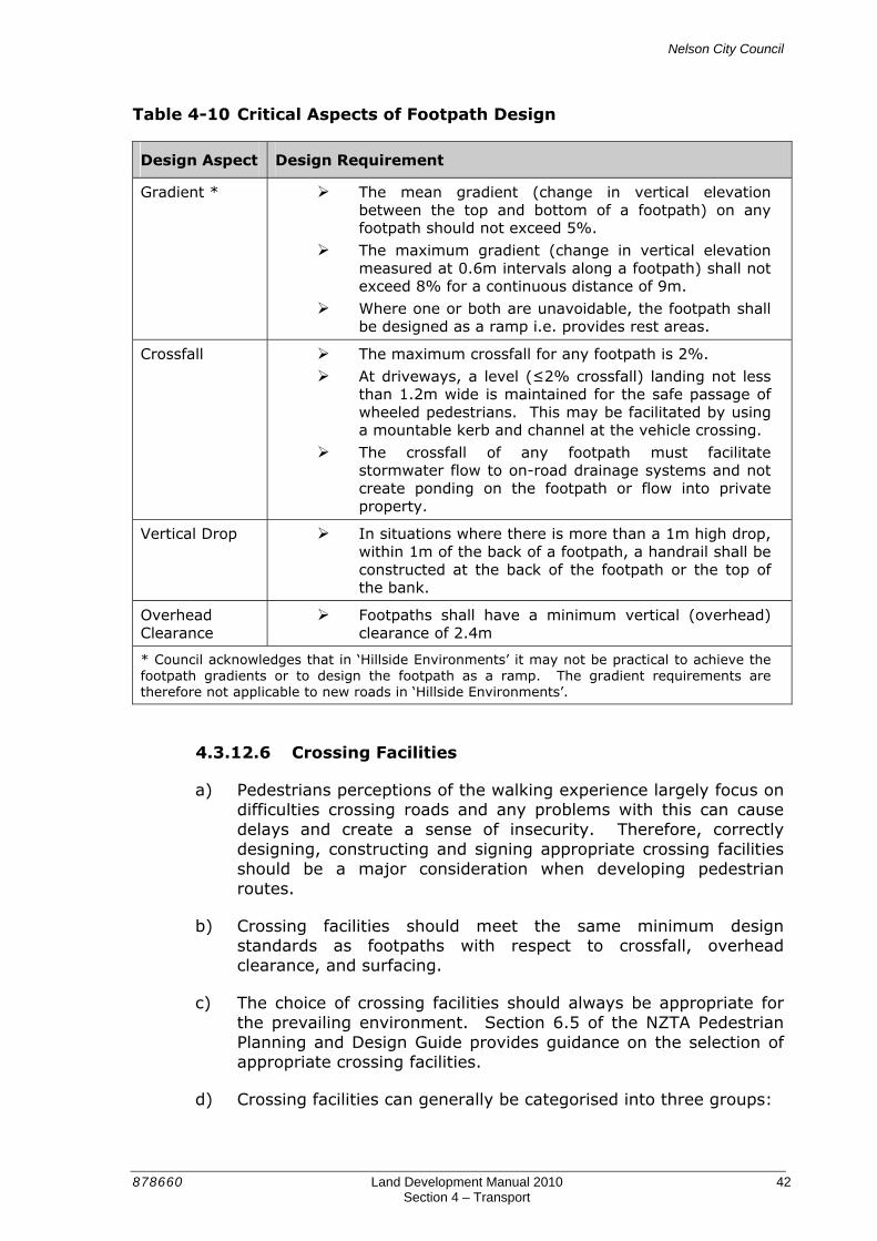
Nelson City Council
878660 Land Development Manual 2010 42 Section 4 – Transport
Table 4-10 Critical Aspects of Footpath Design
Design Aspect Design Requirement
Gradient * The mean gradient (change in vertical elevation between the top and bottom of a footpath) on any footpath should not exceed 5%.
The maximum gradient (change in vertical elevation measured at 0.6m intervals along a footpath) shall not exceed 8% for a continuous distance of 9m.
Where one or both are unavoidable, the footpath shall be designed as a ramp i.e. provides rest areas.
Crossfall The maximum crossfall for any footpath is 2%.
At driveways, a level (≤2% crossfall) landing not less than 1.2m wide is maintained for the safe passage of wheeled pedestrians. This may be facilitated by using a mountable kerb and channel at the vehicle crossing.
The crossfall of any footpath must facilitate stormwater flow to on-road drainage systems and not create ponding on the footpath or flow into private property.
Vertical Drop In situations where there is more than a 1m high drop, within 1m of the back of a footpath, a handrail shall be constructed at the back of the footpath or the top of the bank.
Overhead Clearance
Footpaths shall have a minimum vertical (overhead) clearance of 2.4m
* Council acknowledges that in ‘Hillside Environments’ it may not be practical to achieve the footpath gradients or to design the footpath as a ramp. The gradient requirements are therefore not applicable to new roads in ‘Hillside Environments’.
4.3.12.6 Crossing Facilities
a) Pedestrians perceptions of the walking experience largely focus on difficulties crossing roads and any problems with this can cause delays and create a sense of insecurity. Therefore, correctly designing, constructing and signing appropriate crossing facilities should be a major consideration when developing pedestrian routes.
b) Crossing facilities should meet the same minimum design standards as footpaths with respect to crossfall, overhead clearance, and surfacing.
c) The choice of crossing facilities should always be appropriate for the prevailing environment. Section 6.5 of the NZTA Pedestrian Planning and Design Guide provides guidance on the selection of appropriate crossing facilities.
d) Crossing facilities can generally be categorised into three groups:
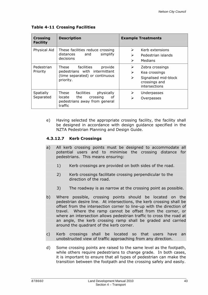
Nelson City Council
878660 Land Development Manual 2010 43 Section 4 – Transport
Table 4-11 Crossing Facilities
Crossing Facility
Description Example Treatments
Physical Aid These facilities reduce crossing distances and simplify decisions
Kerb extensions
Pedestrian islands
Medians
Pedestrian Priority
These facilities provide pedestrians with intermittent (time separated) or continuous priority.
Zebra crossings
Kea crossings
Signalised mid-block crossings and intersections
Spatially Separated
These facilities physically locate the crossing of pedestrians away from general traffic
Underpasses
Overpasses
e) Having selected the appropriate crossing facility, the facility shall be designed in accordance with design guidance specified in the NZTA Pedestrian Planning and Design Guide.
4.3.12.7 Kerb Crossings
a) All kerb crossing points must be designed to accommodate all potential users and to minimise the crossing distance for pedestrians. This means ensuring:
1) Kerb crossings are provided on both sides of the road.
2) Kerb crossings facilitate crossing perpendicular to the direction of the road.
3) The roadway is as narrow at the crossing point as possible.
b) Where possible, crossing points should be located on the pedestrian desire line. At intersections, the kerb crossing shall be offset from the intersection corner to line-up with the direction of travel. Where the ramp cannot be offset from the corner, or where an intersection allows pedestrian traffic to cross the road at an angle, the kerb crossing ramp shall be graded and carried around the quadrant of the kerb corner.
c) Kerb crossings shall be located so that users have an unobstructed view of traffic approaching from any direction.
d) Some crossing points are raised to the same level as the footpath, while others require pedestrians to change grade. In both cases, it is important to ensure that all types of pedestrian can make the transition between the footpath and the crossing safely and easily.

Nelson City Council
878660 Land Development Manual 2010 44 Section 4 – Transport
4.3.12.8 Tactile Paving
a) The layout and installation of tactile paving shall be in accordance with the NZTA Road and Traffic Guideline RTS 14 ‘Guidelines for facilities for blind and vision-impaired pedestrians’.
b) Tactile paving shall be installed on all new and upgraded roads at all kerb crossings and other places where the footpath is not separated from the carriageway by an abrupt change in grade (more than 1 in 8) or vertical kerb face (higher than 70mm).
c) Tactile paving shall provide a high visual contrast to the adjoining walking surface. ‘Safety Yellow’ is the preferred colour standard for tactile paving.
d) An example of tactile paving is shown in Figure 4-I.
Figure 4-I Tactile Paving
4.3.13 Cycling
a) A safe, convenient and legible cycle network (cycleway) should be provided for both experienced and less experienced cyclists. The network may comprise both on-road and off-road routes, planned in accordance with Nelson’s Cycling Strategy. Off-road routes usually provide linkages for pedestrians as well as cyclists.
b) An attractive and well-connected road network will encourage more people to cycle to local destinations, thus improving their health and reducing reliance on the private motor vehicle as a form of transport.

Nelson City Council
878660 Land Development Manual 2010 45 Section 4 – Transport
4.3.13.1 On-Road Cycle Lanes
a) On-road cycle lanes shall be provided on all ‘Classified Roads’, except in ‘Hillside Environments’ where cycle lanes may be excluded in the downhill direction.
b) Cycle lanes are generally not required on ‘Unclassified Roads’ because these roads typically have low traffic volumes and are designed to achieve operating speeds that facilitate safe cycling in a mixed traffic environment. The following guidance directs the need to provide cycle lanes on these lower order roads:
1) Roads that have a speed environment of 40km/h or lower and carry less than 5,000 vehicles per day (vpd) do not require specific provision for cyclists.
2) Roads that have a speed environment of 50km/h and carry more than 2,500 vehicles per day should be designed to accommodate cyclists separately from the traffic lane.
3) Roads that have a speed environment of 60km/h or more should be designed to accommodate cyclists separately from the traffic lane.
c) In addition to the above, cycle lanes should be considered on ‘Unclassified Roads’ in the immediate vicinity of schools.
d) The design of mid-block on-road cycle lanes shall generally comply with the principles specified in the New Zealand Supplement to Austroads Guide to Traffic Engineering Practice, Part 14: Bicycles (September 2008) and the dimensions specified in Table 4-12 below.
Table 4-12 Desirable Width of On-Road Cycle Lanes
Speed Environment Cycle Lane Location
≤ 50km/h 70km/h 100km/h
Adjacent to kerb 1 1.5 1.9 2.5
Adjacent to parallel parking 1.8 2.2 - 1 Assumes the channel provides a suitable profile and surface for cycling i.e. includes cycle friendly sump grates.
e) Cycle lanes located adjacent to angled parking need to provide a clear space buffer between parked vehicles and the cycle lane to provide an exiting vehicle with adequate visibility to approaching cyclists. The clear space buffer varies with the parking angle as shown in Table 4-13.
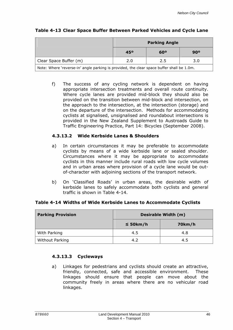
Nelson City Council
878660 Land Development Manual 2010 46 Section 4 – Transport
Table 4-13 Clear Space Buffer Between Parked Vehicles and Cycle Lane
Parking Angle
45º 60º 90º
Clear Space Buffer (m) 2.0 2.5 3.0
Note: Where ‘reverse-in’ angle parking is provided, the clear space buffer shall be 1.0m.
f) The success of any cycling network is dependent on having appropriate intersection treatments and overall route continuity. Where cycle lanes are provided mid-block they should also be provided on the transition between mid-block and intersection, on the approach to the intersection, at the intersection (storage) and on the departure of the intersection. Methods for accommodating cyclists at signalised, unsignalised and roundabout intersections is provided in the New Zealand Supplement to Austroads Guide to Traffic Engineering Practice, Part 14: Bicycles (September 2008).
4.3.13.2 Wide Kerbside Lanes & Shoulders
a) In certain circumstances it may be preferable to accommodate cyclists by means of a wide kerbside lane or sealed shoulder. Circumstances where it may be appropriate to accommodate cyclists in this manner include rural roads with low cycle volumes and in urban areas where provision of a cycle lane would be out-of-character with adjoining sections of the transport network.
b) On ‘Classified Roads’ in urban areas, the desirable width of kerbside lanes to safely accommodate both cyclists and general traffic is shown in Table 4-14.
Table 4-14 Widths of Wide Kerbside Lanes to Accommodate Cyclists
Desirable Width (m) Parking Provision
≤ 50km/h 70km/h
With Parking 4.5 4.8
Without Parking 4.2 4.5
4.3.13.3 Cycleways
a) Linkages for pedestrians and cyclists should create an attractive, friendly, connected, safe and accessible environment. These linkages should ensure that people can move about the community freely in areas where there are no vehicular road linkages.
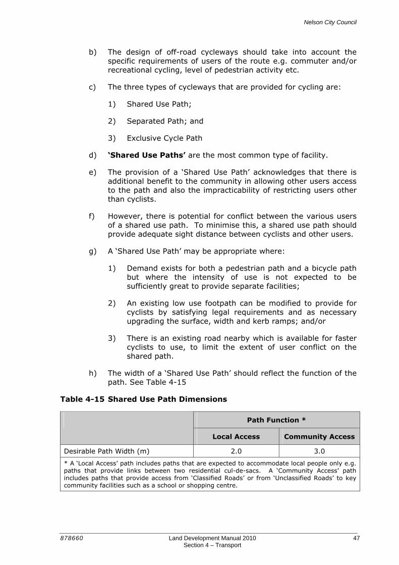
Nelson City Council
878660 Land Development Manual 2010 47 Section 4 – Transport
b) The design of off-road cycleways should take into account the specific requirements of users of the route e.g. commuter and/or recreational cycling, level of pedestrian activity etc.
c) The three types of cycleways that are provided for cycling are:
1) Shared Use Path;
2) Separated Path; and
3) Exclusive Cycle Path
d) ‘Shared Use Paths’ are the most common type of facility.
e) The provision of a ‘Shared Use Path’ acknowledges that there is additional benefit to the community in allowing other users access to the path and also the impracticability of restricting users other than cyclists.
f) However, there is potential for conflict between the various users of a shared use path. To minimise this, a shared use path should provide adequate sight distance between cyclists and other users.
g) A ‘Shared Use Path’ may be appropriate where:
1) Demand exists for both a pedestrian path and a bicycle path but where the intensity of use is not expected to be sufficiently great to provide separate facilities;
2) An existing low use footpath can be modified to provide for cyclists by satisfying legal requirements and as necessary upgrading the surface, width and kerb ramps; and/or
3) There is an existing road nearby which is available for faster cyclists to use, to limit the extent of user conflict on the shared path.
h) The width of a ‘Shared Use Path’ should reflect the function of the path. See Table 4-15
Table 4-15 Shared Use Path Dimensions
Path Function *
Local Access Community Access
Desirable Path Width (m) 2.0 3.0
* A ‘Local Access’ path includes paths that are expected to accommodate local people only e.g. paths that provide links between two residential cul-de-sacs. A ‘Community Access’ path includes paths that provide access from ‘Classified Roads’ or from ‘Unclassified Roads’ to key community facilities such as a school or shopping centre.
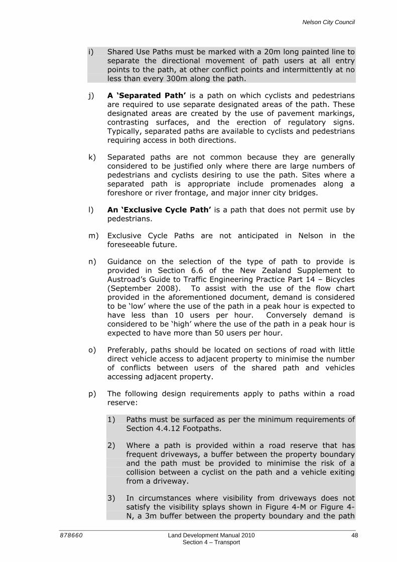
Nelson City Council
878660 Land Development Manual 2010 48 Section 4 – Transport
i) Shared Use Paths must be marked with a 20m long painted line to separate the directional movement of path users at all entry points to the path, at other conflict points and intermittently at no less than every 300m along the path.
j) A ‘Separated Path’ is a path on which cyclists and pedestrians are required to use separate designated areas of the path. These designated areas are created by the use of pavement markings, contrasting surfaces, and the erection of regulatory signs. Typically, separated paths are available to cyclists and pedestrians requiring access in both directions.
k) Separated paths are not common because they are generally considered to be justified only where there are large numbers of pedestrians and cyclists desiring to use the path. Sites where a separated path is appropriate include promenades along a foreshore or river frontage, and major inner city bridges.
l) An ‘Exclusive Cycle Path’ is a path that does not permit use by pedestrians.
m) Exclusive Cycle Paths are not anticipated in Nelson in the foreseeable future.
n) Guidance on the selection of the type of path to provide is provided in Section 6.6 of the New Zealand Supplement to Austroad’s Guide to Traffic Engineering Practice Part 14 – Bicycles (September 2008). To assist with the use of the flow chart provided in the aforementioned document, demand is considered to be ‘low’ where the use of the path in a peak hour is expected to have less than 10 users per hour. Conversely demand is considered to be ‘high’ where the use of the path in a peak hour is expected to have more than 50 users per hour.
o) Preferably, paths should be located on sections of road with little direct vehicle access to adjacent property to minimise the number of conflicts between users of the shared path and vehicles accessing adjacent property.
p) The following design requirements apply to paths within a road reserve:
1) Paths must be surfaced as per the minimum requirements of Section 4.4.12 Footpaths.
2) Where a path is provided within a road reserve that has frequent driveways, a buffer between the property boundary and the path must be provided to minimise the risk of a collision between a cyclist on the path and a vehicle exiting from a driveway.
3) In circumstances where visibility from driveways does not satisfy the visibility splays shown in Figure 4-M or Figure 4-N, a 3m buffer between the property boundary and the path
Nelson City Council
878660 Land Development Manual 2010 49 Section 4 – Transport
must be provided, see Figure 4-J. In circumstances where visibility from driveways satisfies the visibility splays, the buffer may be reduced to 1.5m.
4) The path must be buffered from the carriageway by at least 0.7m, see Figure 4-K. A berm must be provided between the path and carriageway where kerbside parking is permitted to avoid conflict between cyclists and opening doors on the left hand side of vehicles. Paths located against the kerb also create issues on rubbish collection days, as rubbish for collection is usually placed kerbside.
5) A minimum lateral clearance of 0.5m (desirably 1.0m) must be provided between the edge of the path and any obstacle, including vegetation, light standards, signs, utility furniture, bollards etc.
Figure 4-J Path Buffers
4.3.13.4 Accessways
a) Accessways are linkages for pedestrians and cyclists that do not run alongside a vehicular carriageway but link road to road or road to reserve. See Figure 4-K.
b) The width of an Accessway path shall be consistent with the Shared Use Path Dimensions specified in Table 4-15. The minimum legal reserve width of any Accessway shall be 6m including berms and landscaping. Refer to SD 429 for detailed design information.
3m buffer from bdy
Min 0.7m buffer

Nelson City Council
878660 Land Development Manual 2010 50 Section 4 – Transport
Figure 4-K Accessway with Berm and Landscaping
c) Accessways must be designed in accordance with Nelson City Council’s Safer by Design (CPTED) Guidelines and so that a person using the Accessway can see from one end of the accessway to the other at all times.

Nelson City Council
878660 Land Development Manual 2010 51 Section 4 – Transport
4.3.14 Streetscape
a) Streetscape elements include paving, berms, street trees, plant beds, streetlights and street furniture. Landscaping and street furniture in particular can create a visually attractive and interesting environment to encourage more use of the road as a public place. Landscaping and street trees can also provide a ‘buffer’ between the footpath and the carriageway, create the perception of a narrower road and encourage drivers to travel more slowly and may also provide shade and shelter.
4.3.14.1 Berms
a) Berms are the areas between the edge of the carriageway and the property boundary, not including footpaths. Berms provide numerous functions, including:
1) Space for pedestrians to pass
2) Access to and from parked vehicles
3) A corridor for underground utilities such as water, power and telecommunications
4) The planting of street trees and plant beds
b) Where possible, a services free berm at least 1.5m wide shall be provided between the carriageway and the footpath for the establishment of street trees.
c) Berms typically have a grassed surface. For the berm between the kerb and the footpath (where the footpath is offset from the kerb) Council may allow the following options as an alternative to grassed surfaces:
1) A crushed stone; or
2) An ornamental ground cover; or
3) More extensive landscaping where there is no parking adjacent the kerb.
d) For the berm between the footpath and the road boundary, residents are permitted to establish their own landscaping plants and ground cover as an alternative to grass provided the total width from the edge of the carriageway and the edge of the property berm is at least 2.0m and complies with the following requirements:
1) All vegetation shall be maintained to be no closer than 150mm to the edge of the footpath. Overhanging vegetation that maintains a 2.4m envelope above the footpath is permitted.
Nelson City Council
878660 Land Development Manual 2010 52 Section 4 – Transport
2) Boulders shall not be larger than 300mm equivalent spherical diameter.
3) Retaining structures shall not be installed.
4) Ground levels shall not be raised more than 500mm. Ground levels shall not be lowered.
5) Appropriate sight-lines shall be preserved at vehicle entrances and around corners.
6) Trees are not permitted.
e) The slope of the grass berms from kerb to boundary shall generally be 1 in 33 (3%). This slope may vary, but shall not be less than 1 in 50 (2%) nor more than 1 in 12 (8%).
4.3.14.2 Street Trees and Landscaping
a) Opportunities for street trees and landscaping shall be taken where possible to improve the visual amenity of roads in Nelson. Landscaping shall be designed to meet the following objectives:
1) Functional - Provide a sense of separation between the road and the footpath.
- Provide shade.
- Integrate with the network of reserves and open space.
2) Safety - Maintain adequate visibility for road users.
- Maintain adequate visibility from residential properties to the road.
- Adequate separation from parking areas.
- Avoid obstructions to pedestrians.
3) Aesthetic - Frame views.
- Emphasise landscape features.
- Soften hard surfaces.
- Enhance aesthetic values.
b) Street trees are to be provided on services free berms that are at least 1.5m wide or services free paved areas within the inner city or commercial areas as appropriate. Street trees planted within berms shall be provided in accordance with SD 1201 and within

Nelson City Council
878660 Land Development Manual 2010 53 Section 4 – Transport
pavement areas they shall be provided in accordance with SD 1202.
c) No trees or shrubs shall be planted within a 2.0m radius of any water valve or hydrant.
d) Street trees and landscaping species must be selected and located so that future growth will not impede pedestrian flow, compromise the integrity and efficient operation of infrastructure services, or reduce visibility on curves or at driveways.
e) The positioning of street trees within the road must not create a hazard to vehicles that leave the road. Non-frangible trees i.e. trees with a trunk of more 100mm diameter measured 400mm above ground surface at maturity shall be positioned so that the clear zones specified in Table 4-18 or Table 4-19 are satisfied.
f) Section 12 Reserves and Landscaping of the Land Development Manual provides detailed requirements for street tree planting.
4.3.14.3 Street Furniture
a) Every piece and type of street furniture shall be easily detectable (and avoidable) by the vision impaired. This means each street furniture element must:
1) Be at least 1m high.
2) Have an element within 150mm of the ground for its entire length parallel to the ground, so that it is detectable by a vision impaired person with a cane.
3) Be placed so that the minimum ‘Through Route’ widths are maintained. See Table 14.3 of the NZTA Pedestrian Planning and Design Guide.
4) Be placed in a consistent manner to promote the confident movement of vision impaired persons.
b) All street furniture that is located within 4m of the edge of the nearest traffic lane on roads that have a speed environment above 50km/h shall be collapsible or frangible so as not to create a hazard for vehicles that leave the road.
c) Street furniture design should be sympathetic to the surrounding environment and, where it is intended for use by pedestrians, should be accessible to all types.
d) Typical characteristics and conventional locations of common street furniture for new or upgraded streets roads are shown in Table 14.9 of the NZTA Pedestrian Planning and Design Guide.

Nelson City Council
878660 Land Development Manual 2010 54 Section 4 – Transport
4.3.15 Property Access
a) Every property is entitled to have vehicular access to the road network. However, the proliferation of access points may produce many negative effects, including:
1) Increasing the number of conflict points with people walking and cycling on shared paths and footpaths.
2) Reducing the area of berm that is available for landscaping, street trees and street furniture, thereby reducing the amenity of the road environment.
3) Reducing the amount of on-road parking that is available.
b) The Land Development Manual covers the design and construction aspects of vehicle crossings between the road and private property, including the transition between private property and the road.
c) Design standards and planning rules governing on-site parking and manoeuvring matters are presented in Appendix 10 ‘Standards and Terms for Parking and Loading’ of the Nelson Resource Management Plan. Planning rules governing the number and spacing of access points is presented in Appendix 11 ‘Access Standards’ of the Nelson Resource Management Plan.
d) All vehicle kerb crossings are to ensure the satisfactory passage of the applicable design vehicle for the nature and size of the activity. Appendix 12 ‘Tracking Paths’ of the Nelson Resource Management Plan specifies tracking and vehicle clearances for a number of design vehicles.
4.3.15.1 Width of Vehicle Access Points
a) In residential areas, vehicle access points shall have dropped kerb width of between 3.5m and 6.0m. Refer to SD 409 and 410 for design details.
b) In commercial areas, but excluding service stations and where verandas are required, vehicle access points shall have dropped kerb width of between 5.0m and 7.0m. Refer to SD 409 and 410 for design details.
c) In industrial areas, vehicle access points shall have dropped kerb width of between 6.0m and 8.0m. Refer to SD 409 and 410 for design details.
d) Where 'B trains' will be using a vehicle entrance on a regular basis, a crossing width of 9.0m may be permitted on specific application to the Council.

Nelson City Council
878660 Land Development Manual 2010 55 Section 4 – Transport
e) In the case of adjacent property owners in any zone wishing to have a mutual crossing at their shared boundary, the maximum permitted total length is 8.0m.
f) In all cases the first 2m of the access formation from legal boundary shall be at right angles to the carriageway formation.
g) Continuous vehicle crossings may be used within the turning head of a cul-de-sac provided the footpath is offset from the carriageway by at least 1.5m.
4.3.15.2 Domestic Driveway Gradients
a) Definition: A domestic driveway is any vehicular path providing access to three or fewer residential units.
b) Critical aspects of domestic driveway design with respect to gradient are (also refer to Figure 4-L):
1) The maximum gradient of a domestic driveway shall be 1 in 4 (25%).
2) The maximum gradient of a domestic driveway across the property line shall be 1 in 20 (5%).
3) The maximum gradient of a domestic driveway that crosses a footpath or path shall be 1 in 50 (2%) for a lateral distance of at least 1.2m within that footpath or path.
c) Grade changes across a footpath and within private property are required to ensure vehicles will not scrape their undersides. Grade transitions of 2.0m long are required whenever the ramp grade changes by more than 12.5%. Refer to ‘AS/NZS 2890.1:2004 Parking facilities – Part 1: Off-street car parking’ for detailed design guidance.
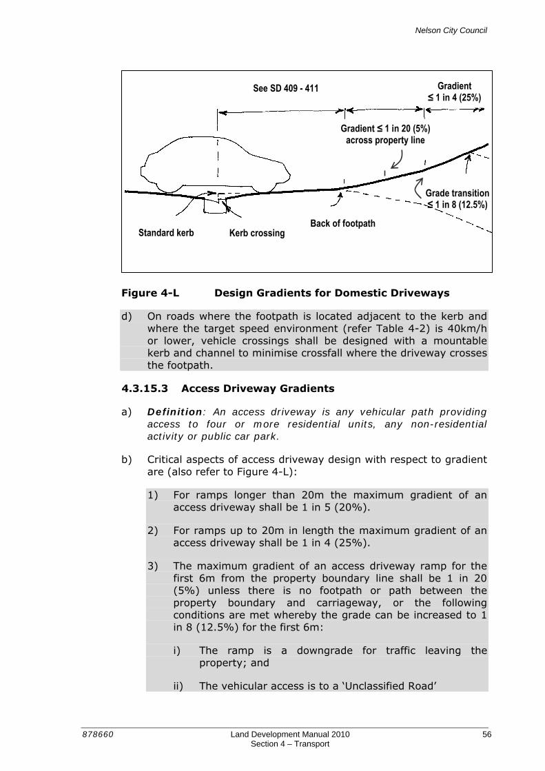
Nelson City Council
878660 Land Development Manual 2010 56 Section 4 – Transport
Figure 4-L Design Gradients for Domestic Driveways
d) On roads where the footpath is located adjacent to the kerb and where the target speed environment (refer Table 4-2) is 40km/h or lower, vehicle crossings shall be designed with a mountable kerb and channel to minimise crossfall where the driveway crosses the footpath.
4.3.15.3 Access Driveway Gradients
a) Definition: An access driveway is any vehicular path providing access to four or more residential units, any non-residential activity or public car park.
b) Critical aspects of access driveway design with respect to gradient are (also refer to Figure 4-L):
1) For ramps longer than 20m the maximum gradient of an access driveway shall be 1 in 5 (20%).
2) For ramps up to 20m in length the maximum gradient of an access driveway shall be 1 in 4 (25%).
3) The maximum gradient of an access driveway ramp for the first 6m from the property boundary line shall be 1 in 20 (5%) unless there is no footpath or path between the property boundary and carriageway, or the following conditions are met whereby the grade can be increased to 1 in 8 (12.5%) for the first 6m:
i) The ramp is a downgrade for traffic leaving the property; and
ii) The vehicular access is to a ‘Unclassified Road’
Standard kerb Kerb crossing Back of footpath
See SD 409 - 411
Gradient ≤ 1 in 20 (5%) across property line
Gradient ≤ 1 in 4 (25%)
Grade transition ≤ 1 in 8 (12.5%)
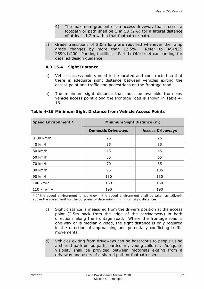
Nelson City Council
878660 Land Development Manual 2010 57 Section 4 – Transport
4) The maximum gradient of an access driveway that crosses a footpath or path shall be 1 in 50 (2%) for a lateral distance of at least 1.2m within that footpath or path.
c) Grade transitions of 2.0m long are required whenever the ramp grade changes by more than 12.5%. Refer to ‘AS/NZS 2890.1:2004 Parking facilities – Part 1: Off-street car parking’ for detailed design guidance.
4.3.15.4 Sight Distance
a) Vehicle access points need to be located and constructed so that there is adequate sight distance between vehicles exiting the access point and traffic and pedestrians on the frontage road.
b) The minimum sight distance that must be available from any vehicle access point along the frontage road is shown in Table 4-16.
Table 4-16 Minimum Sight Distance from Vehicle Access Points
Minimum Sight Distance (m) Speed Environment *
Domestic Driveways Access Driveways
≤ 30 km/h 25 25
40 km/h 35 35
50 km/h 45 45
60 km/h 55 65
70 km/h 70 85
80 km/h 95 105
90 km/h 130 130
100 km/h 160 160
110 km/h + 190 190
* If the speed environment is not known, the speed environment shall be taken as 10km/h above the speed limit for the purposes of determining minimum sight distances.
c) Sight distance is measured from the driver’s position at the access
point (2.5m back from the edge of the carriageway) in both directions along the frontage road. Where the frontage road is one-way or is median divided, the sight distance is only required in the direction of approaching and potentially conflicting traffic movements.
d) Vehicles exiting from driveways can be hazardous to people using a shared path or footpath, particularly young children. Adequate visibility shall be provided between motorists exiting from a driveway and users of a shared path or footpath users.
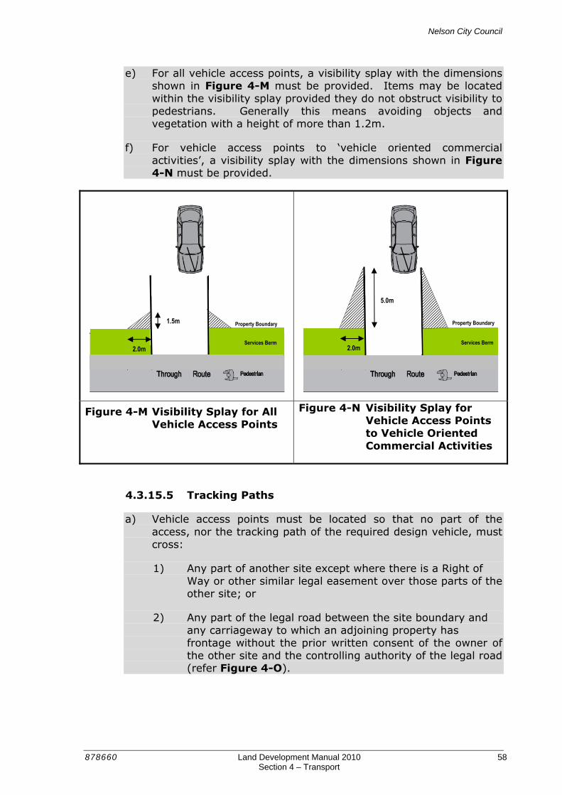
Nelson City Council
878660 Land Development Manual 2010 58 Section 4 – Transport
e) For all vehicle access points, a visibility splay with the dimensions shown in Figure 4-M must be provided. Items may be located within the visibility splay provided they do not obstruct visibility to pedestrians. Generally this means avoiding objects and vegetation with a height of more than 1.2m.
f) For vehicle access points to ‘vehicle oriented commercial activities’, a visibility splay with the dimensions shown in Figure 4-N must be provided.
Figure 4-M Visibility Splay for All Vehicle Access Points
Figure 4-N Visibility Splay for Vehicle Access Points to Vehicle Oriented Commercial Activities
4.3.15.5 Tracking Paths
a) Vehicle access points must be located so that no part of the access, nor the tracking path of the required design vehicle, must cross:
1) Any part of another site except where there is a Right of Way or other similar legal easement over those parts of the other site; or
2) Any part of the legal road between the site boundary and any carriageway to which an adjoining property has frontage without the prior written consent of the owner of the other site and the controlling authority of the legal road (refer Figure 4-O).
Services Berm
Property Boundary Property Boundary
Services Berm
1.5m
5.0m
2.0m 2.0m
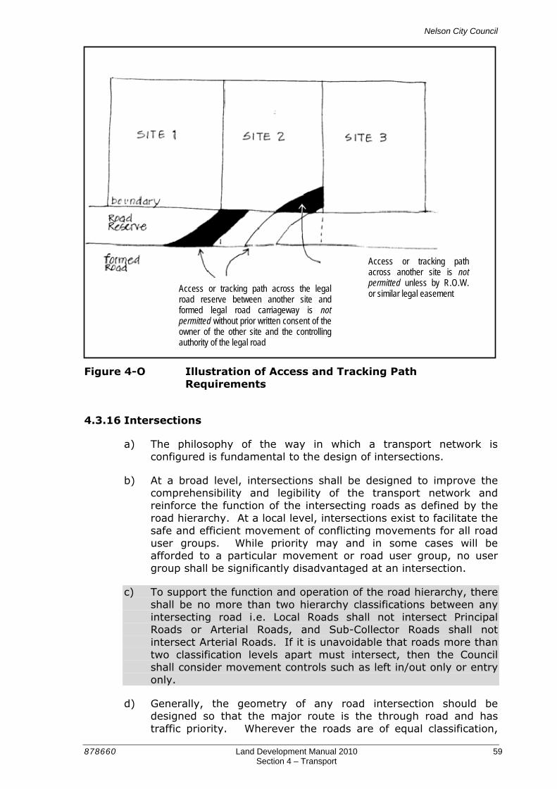
Nelson City Council
878660 Land Development Manual 2010 59 Section 4 – Transport
Figure 4-O Illustration of Access and Tracking Path
Requirements
4.3.16 Intersections
a) The philosophy of the way in which a transport network is configured is fundamental to the design of intersections.
b) At a broad level, intersections shall be designed to improve the comprehensibility and legibility of the transport network and reinforce the function of the intersecting roads as defined by the road hierarchy. At a local level, intersections exist to facilitate the safe and efficient movement of conflicting movements for all road user groups. While priority may and in some cases will be afforded to a particular movement or road user group, no user group shall be significantly disadvantaged at an intersection.
c) To support the function and operation of the road hierarchy, there shall be no more than two hierarchy classifications between any intersecting road i.e. Local Roads shall not intersect Principal Roads or Arterial Roads, and Sub-Collector Roads shall not intersect Arterial Roads. If it is unavoidable that roads more than two classification levels apart must intersect, then the Council shall consider movement controls such as left in/out only or entry only.
d) Generally, the geometry of any road intersection should be designed so that the major route is the through road and has traffic priority. Wherever the roads are of equal classification,
Access or tracking path across another site is not permitted unless by R.O.W. or similar legal easement Access or tracking path across the legal
road reserve between another site and formed legal road carriageway is not permitted without prior written consent of the owner of the other site and the controlling authority of the legal road

Nelson City Council
878660 Land Development Manual 2010 60 Section 4 – Transport
traffic volumes and the nature of upstream and downstream intersections will inform the decision of which approach is provided with priority. In some circumstances it may be appropriate to control these intersections with a roundabout or for the intersection of classified roads with traffic signals.
e) The potential for crashes to occur at intersections is higher than other areas of the road network, due to the number of conflicting vehicle, cycle and pedestrian movements. Proper design of intersections can reduce the number of conflicts, while providing for a range of turning movements at the intersection.
4.3.16.1 Intersection Design
a) Intersections shall be designed in accordance with the guidance provided in Austroad’s Guide to Traffic Management: Part 6 – Intersections, Interchanges and Crossings. Where any conflict exists between that guide and the Land Development Manual, the Land Development Manual shall take precedence.
b) Refer to Sections 4.3.2 and 4.3.8.8 of the Land Development Manual for intersection spacing and intersection radii design guidance.
4.3.16.2 Safe Intersection Sight Distance
a) Safe Intersection Sight Distance (SISD) is the distance required for the driver of a vehicle on the non-terminated approach to observe a vehicle entering from a side road, decelerate and stop prior to a point of conflict. It is also generally sufficient to enable cars to cross a major road safely from a side road.
b) SISD is the minimum sight distance that should be available from intersection legs with priority to vehicles which could emerge from non-signalised legs.
c) SISD shall be provided at all intersections. It is measured along the carriageway from the approaching vehicle to the conflict point.
d) SISD is viewed between two points 1.15m above the road surface. One point is the driver's eye height on the leg with priority and the other represents eye height of a driver in the side road. The driver in the side road is assumed to sit at a distance of 5.0m from the lip of the kerb or edge line projection of the major road.
e) SISD allows for a 3 second observation time for a driver on the through leg of the intersection to detect the problem ahead e.g. car from minor road stalling in through lane, plus safe Stopping Sight Distance (SSD).
f) SISD is to be provided in accordance with Table 4-17.

Nelson City Council
878660 Land Development Manual 2010 61 Section 4 – Transport
Table 4-17 Safe Intersection Sight Distance (SISD)
Speed Environment Safe Intersection Sight Distance (m) *
≤ 30 km/h 50
40 km/h 70
50 km/h 90
60 km/h 115
70 km/h 140
80 km/h 180
90 km/h 215
100 km/h 255
110 km/h + 300
* As required on level grade. Correction factors are to be applied on non-level roads in a manner that is consistent with Austroad’s Guide to Traffic Management: Part 6 – Intersections, Interchanges and Crossings.
4.3.16.3 Types of Intersections
Priority Intersections
a) Give Way and Stop controlled (priority controlled) intersections and uncontrolled intersections are the most common form of intersection control in Nelson, especially on intersections where one approach is a ‘Unclassified Road’.
b) These intersections promote movements dictated by the road hierarchy i.e. prioritise movement on higher order roads over lower order roads.
c) The selection of Give Way or Stop control is primarily governed by sight distance from the minor leg. A Stop control is appropriate when:
1) Visibility measured from a point 9m back from the limit line on the side road does not provided sufficient visibility to see a vehicle on an uncontrolled approach at a distance measured in metres that is 1.2 times the speed environment e.g. 60m in a 50km/h speed environment; or
2) Intersections have an unusual layout or unusual traffic pattern where it is essential to give one controlled approach priority over another controlled approach.
d) A Give Way control is appropriate when:
1) Crossroads do not have visibility constraints requiring Stop signs; and
2) Intersections have an unusual layout, or an unusual traffic pattern, to clearly define who should give way, where it is

Nelson City Council
878660 Land Development Manual 2010 62 Section 4 – Transport
otherwise desirable to override the normal application of the right-hand rule, e.g. at T-intersections with ‘Classified Roads’.
e) In the absence of Give Way or Stop signs, traffic is controlled by traffic regulations. In New Zealand, current traffic regulations require right turning vehicles on the main road to give way to right turning vehicles exiting from the minor (stem) leg and right turning traffic has priority over conflicting left turning traffic.
f) Intersections within residential areas should primarily be T-intersections for safety reasons. However, to improve connectivity, especially for pedestrians, Council will consider the use of four-way intersections. As priority intersections do not afford any priority to pedestrians, consideration should be given to providing traffic calming or physical crossing aids to improve pedestrian crossing opportunities. This may be achieved through the use of facilities such as kerb extensions, intersection platforms, raised medians and pedestrian islands.
g) The provision of a threshold treatment on a lower order road, as shown in Figure 4-P, will also reinforce traffic priority and assist with comprehending the intersection layout.
Figure 4-P Intersection Threshold Treatment
h) Priority controlled four-way intersections may be an appropriate form of intersection treatment in residential areas where all intersecting roads are ‘Unclassified Roads’ that have an approach speed environment of no more than 40km/h and where the total number of vehicles passing through this type of intersection should not exceed 2,000 vehicles per day.

Nelson City Council
878660 Land Development Manual 2010 63 Section 4 – Transport
i) Where higher traffic volumes are anticipated, the intersection should be controlled with a roundabout or the intersection redesigned as a three-leg T-intersection.
j) An example of a four-way Stop controlled intersection is shown in Figure 4-Q.
Figure 4-Q Four-Way Stop Controlled Intersection
Roundabouts
a) Roundabouts can be used as an effective form of intersection control in a number of situations.
b) Conventionally designed roundabouts with comparatively large central islands and approach deflection are generally not appropriate in residential areas at the intersections of ‘Unclassified Roads’. Their capacity advantages are not usually applicable in these lower traffic volume situations and they can also have a negative impact on walking and cycling. Larger roundabouts are inconvenient for pedestrians because they are deflected from their desire lines, and people waiting to cross one of the arms may not be able to anticipate easily the movement of motor vehicles on the roundabout, or entering or leaving it.
c) The preferred form of roundabouts at intersections of ‘Unclassified Roads’ incorporates a semi-mountable apron, as shown in Figure 4-R. A well-designed roundabout with semi-mountable apron will slow cars whilst providing for the larger turning requirements of vehicles such as buses, waste collection vehicles and emergency vehicles.

Nelson City Council
878660 Land Development Manual 2010 64 Section 4 – Transport
Figure 4-R Roundabout with Semi-Mountable Apron
d) Roundabouts should be designed to ensure low entry and exit speeds. For safety reasons, it is important that comparable levels of visibility to the right are provided on all approaches to ensure that the entry speed of vehicles on any one approach is not substantially different from other approaches.
e) Roundabouts give no priority to pedestrians waiting to cross the intersection. However, roundabouts can be designed to benefit pedestrians, as follows:
1) Splitter islands should incorporate pedestrian island crossing facilities.
2) Approaches and departures can be combined with kerb extensions to reduce crossing distances and reduce vehicle speeds
3) By providing pedestrian platforms where speed environment on an approach is less than 50 km/h. Zebra crossings can be marked on such platforms where the general requirements for zebra crossings are met, and queues generated by crossing pedestrians will not block the roundabout.
f) While roundabouts generally reduce crashes involving pedestrians, they can create problems for the vision impaired pedestrians due to confusing auditory signals from approaching and circulating vehicles.
g) Roundabouts can also be hazardous for cyclists. Drivers entering at relatively high speed may not notice cyclists on the circulatory carriageway, and cyclists travelling past an arm are vulnerable to being hit by vehicles entering or leaving the junction.

Nelson City Council
878660 Land Development Manual 2010 65 Section 4 – Transport
h) When considering installing multi-lane roundabouts, walking and cycling needs to be carefully considered.
i) The design of roundabouts shall be in accordance with Austroad’s Guide to Traffic Management: Part 6 – Intersections, Interchanges and Crossings.
Traffic Signals
a) Traffic signals separate conflicting road user movements on a time basis.
b) The primary factor in proposing use of traffic signals has to do with the availability of safe gaps. If the gaps in the major street flow can safely accommodate entering traffic from side streets for the majority of the time, it is reasonable to assume that traffic signals are not required. However, as vehicle volumes increase, the likelihood of having to provide traffic signals increases. Detailed information on warrants for installing traffic signals is provided in Austroad’s Guide to Traffic Management: Part 6 – Intersections, Interchanges and Crossings
c) Traffic signals may be a viable option where there is an accident history at an unsignalised intersection that greatly exceeds that which would be predicted for the intersection type and traffic volumes. Refer to the NZTA Economic Evaluation Manual for details.
d) At busy junctions requiring multiple approach lanes, traffic signals are generally preferred over roundabouts.
e) The location and design of each installation must conform to the requirements and approvals set by the Council, to enable coordination of the traffic signals.
f) Traffic signals are perceived by pedestrians as an effective and safe method of crossing the road. This perception is heightened when young, or elderly pedestrians are involved.
4.3.17 Parking
a) Parking is a key function of many roads, although it is not always a requirement. A well-designed arrangement of on-road parking provides convenient access to frontages and can add to the vitality of a road. Conversely, poorly designed parking can create safety problems and reduce the visual amenity of the area.
b) Some of the positive effects of on-road parking are:
1) In residential areas, parked vehicles create the perception of a narrower carriageway, which is likely to reduce vehicle speeds. Research suggests that parked vehicles generally
Nelson City Council
878660 Land Development Manual 2010 66 Section 4 – Transport
create a speed environment that is 3 – 8km/h lower than when parking does not occur.
2) Parked vehicles provide a barrier between traffic lanes and the footpath.
3) That they provide a common resource, catering for residents’, visitors’, customers and service vehicles in an efficient manner.
4) Able to cater for peak demands from various users at different times of the day.
5) Introduces activity to the road environment.
c) Some of the negative effects of on-road parking are:
1) Indiscriminately parked vehicles may make access to fronting properties difficult through restricting visibility and possibly blocking driveways.
2) On narrower roads, there may be a tendency for vehicles to park on footpaths restricting pedestrian movement.
3) On-road parking spaces can visually dominate the road scene and undermine speed objectives, particularly when parking demand is low.
4) Safety issues may arise for pedestrians if high parking demand reduces the availability of crossing opportunities with adequate visibility.
5) Cars parked on-road can be more vulnerable to opportunistic crime than off-road spaces.
d) The above demonstrates the importance of providing an appropriate quantum and type of parking to achieve the different objectives that are sought in different parts of the community.
4.3.17.1 Parking Supply
a) The following factors should be taken into consideration when determining an appropriate level of on-road parking to be provided:
1) The nature of the surrounding land use.
2) The function and geometry of the road.
3) The amount of off-road parking provided.
4) The total amount of parking expected to be generated.
5) The turnover rate of parking that is anticipated.

Nelson City Council
878660 Land Development Manual 2010 67 Section 4 – Transport
b) In residential areas, the rate of on-road parking shall be a minimum of one space per three residential units.
c) The provision of parking on ‘Classified Roads’ shall be determined by Council, giving regard for any relevant parking strategy.
4.3.17.2 Parking Design
a) Parking is most commonly and safely provided parallel to the kerb.
b) Parking that is provided parallel to the traffic lane shall be at least 2.0m wide and no wider than 2.3m. A parking width of 2.0m is appropriate in low turnover parking areas where most parked vehicles are cars. Wider dimensions are more appropriate in high turnover parking areas or where larger vehicles could be expected to park.
c) In residential areas, it is preferable for parking spaces to be visually separated from the carriageway, for instance by the use of different surfacing, as shown in Figure 4-S.
Figure 4-S Different Surfacing Provides Visual Separation between Parking Spaces and the Carriageway
d) Parking bays can break up the visual impact of on-road parking through separating small groups of parking spaces by kerb extensions, street furniture and planting. They generally provide more and safer opportunities for pedestrians to cross at mid-block locations, and contribute to better overall road environment amenity.
e) Parallel parking that is provided as indented bays shall be at least 2.2m wide and no wider than 2.5m. The crossfall of parking bays should be designed to have them drain towards the road. The

Nelson City Council
878660 Land Development Manual 2010 68 Section 4 – Transport
width of any flat kerbside drainage channel may be included as part of parallel parking width dimensions.
f) Parallel parking spaces shall be 5.0m long where access is possible from an end and 6.0m long when between other parking spaces or where access is restricted. Parking spaces shall commence a minimum distance of 6.0m from any side road.
g) In low parking demand areas, parallel parking shall be delineated by a 100mm wide continuous white line parallel to the kerb.
h) In moderate parking demand areas, the extent of parking at intersections and kerb crossings shall be identified with inverted ‘L” or parking tick markings, as defined in Section 2.11.04 of the Manual of Traffic Signs and Markings. The markings shall be located 1.5m from the edge of driveways and other kerb crossing points.
i) Where parking is metered or where there is high parking demand, individual parking spaces shall be marked.
j) Marking is required for all parking on ‘Classified Roads’, and on ‘Unclassified Roads’ where angle parking is provided or where parking restrictions are in place.
k) Angle parking on Local Roads may be designed so that vehicles manoeuvre to and from spaces within the traffic lane. On higher order roads, adequate space must be available for vehicles to manoeuvre to and from spaces completely clear of the traffic lane.
l) Angle parking is only appropriate on roads where the speed limit is 50km/h or less.
m) The dimensions of angle parking spaces shall be in accordance with Austroad’s Guide to Traffic Management: Part 11 - Parking.
4.3.18 Clear Zones
a) The purpose of a clear zone is to provide space for the driver of a vehicle that leaves the traffic lane to regain control while sustaining minimum damage to the vehicle and its occupants.
b) A clear zone is measured from the edge of the traffic lane and is the width of roadside available for the driver to corrective action.
c) To provide this zone, potential hazards such as above ground utilities, road furniture and street trees, lighting columns shall be located at a distance from the edge of the traffic lane greater than the widths shown in Table 4-18 or Table 4-19, whichever is applicable.

Nelson City Council
878660 Land Development Manual 2010 69 Section 4 – Transport
Table 4-18 Clear Zone Widths (Without Kerb)
Speed Environment One Way Daily Traffic Volume
50km/h 70km/h 100km/h
1,000 vpd 3.0 3.4 6.0
5,000 vpd 3.0 5.4 9.0
Table 4-19 Clear Zone Widths (With Kerb)
Speed Environment Road Hierarchy
≤ 50km/h 70km/h 100km/h
Arterial 2.5 3.0 NA
Principal 2.0 3.0 NA
Collector 1.5 3.0 NA
Sub-Collector 1.0 NA NA
Local 1.0 NA NA
Residential Lane 0.75 NA NA
d) The clear zone is most commonly applicable to the left side of the traffic lane. However, on median-divided roads it is also applicable to the right hand side. The clear zone distance is related to predicted traffic volumes and speed and takes into account the widths of adjacent lanes, shoulders, medians, berms, footpaths and traversable batters.
e) To be regarded as part of the clear zone the areas should be:
1) Relatively flat, with a maximum side slope of 1 on 3 (cutting) and desirably 1 on 4 (embankment) or flatter; and
2) Traversable, having slope changes that will keep all wheels of an errant vehicle in contact with the ground (this assists the driver of an errant vehicle to regain control).
3) Clear of all non-collapsible and non-frangible objects. Only objects which will collapse or break away on impact should be located in the clear zone to ensure minimal damage to an errant vehicle and its occupants.
f) Where it is not possible to provide an adequate clear zone, free of non-frangible obstacles for the appropriate distance, a vehicle barrier must be considered. Any vehicle barrier within the clear zone, must include the barrier deflection when determining the offset between the edgeline and the hazard. Guidance on the design and construction of vehicle barriers shall comply with NZTA M23 Notes ‘Notes for Road Safety Barrier Systems' (2009).

Nelson City Council
878660 Land Development Manual 2010 70 Section 4 – Transport
g) Hazards within the clear zone also include vertical drops from features such as drains, culverts and hillside topography. Any vertical drop of more than 1m within the clear zone shall be considered to be a hazard and must be removed or treated to prevent entry by an errant vehicle. A vehicle barrier is likely to be the most common form of treatment.
4.3.19 Utilities
a) The layout of all roads must accommodate infrastructural services and provide convenient access for the maintenance of those services. These can usually be accommodated within a 1 to 2m wide corridor, which is positioned under the berm or under the footpath.
b) For new roads, it is preferable for services to be located under the footpath, particularly in hillside developments to minimise the width of road reserve that is required. Where services will be located under the footpath, the width of the service strip adjacent to the property boundary may be reduced to 0.5m.
c) For upgrades to existing roads or the provision of new services in existing roads, services may be located under the berm adjacent to the property boundary or under the footpath.
d) Services are not permitted to be located in the berm between the footpath and the kerb, as this will preclude the planting of street trees. Where street trees are not proposed, the water pipe may be located in this area.
e) The width between the kerb and property boundary must be designed to provide sufficient clearance between services. In addition, there must be at least 600mm horizontal separation between the power and the property boundary (refer SD 414 and 415).
f) Where street trees are planned, sufficient space must be allowed for them outside of the service corridor with sufficient clearance so that services are not damaged by roots as the trees grow.
4.3.20 Service Vehicles
a) The design of roads shall accommodate service vehicles without allowing their requirements to dominate the layout. On ‘Unclassified Roads’, it may be assumed that they will be able to use the full width of the carriageway to manoeuvre.
b) Larger vehicles which are only expected to use a road infrequently, such as removal vehicles, need not be fully accommodated on ‘Unclassified Roads’.
Nelson City Council
878660 Land Development Manual 2010 71 Section 4 – Transport
c) The design of intersections to accommodate turning requirements of larger vehicles shall follow the principles specified in Section 4.3.8.8 ‘Intersection Radii’ of this Land Development Manual.
d) Well-connected road networks have significant advantages for service vehicles. A shorter route can be used to cover a given area, and reversing may be avoided altogether.
e) However, some sites cannot facilitate such ease of movement (e.g. linear sites and those with difficult topography), and use cul-de-sacs to make the best use of the land available. Turning heads must be provided in cul-de-sacs in accordance with Section 4.3.4.1 ‘Turning Heads’ of this Land Development Manual.
f) The most common type of service vehicle accessing residential areas will be those associated with regular waste collection. The operation of waste collection services should be an integral part of road design and achieved in ways that do not detract from road environment amenity.
g) While it is always possible to design new roads to take the largest vehicle that could be manufactured, this would conflict with the desire to create quality places and create low speed environments in local residential areas. Accordingly, it is important that the authority responsible for waste collection consider potential conflict with the transport objectives of this Land Development Manual when proposing changes to the size of waste collection vehicles.
4.3.21 Road Marking
a) All new and upgraded roads shall provide road marking in accordance with the NZTA Manual of Traffic Signs and Markings (MOTSAM) – Part II Markings.
b) Council requires that:
1) Centrelines are marked on all ‘Classified Roads’ and ‘Unclassified Roads’ that have a speed limit of 60km/h or above.
2) Centrelines are marked on sections of ‘Unclassified Roads’ where insufficient forward visibility is provided between opposing vehicles on narrow carriageways to see each other and stop (refer Table 4-8 for Safe Stopping Sight Distances for various design speeds).
3) Lane lines are installed wherever there is more than one lane in the same direction.
4) Edge lines are marked on all ‘Classified Roads’ and on ‘Unclassified Roads’ in rural areas. Edge lines may also be provided on other roads to improve delineation.
Nelson City Council
878660 Land Development Manual 2010 72 Section 4 – Transport
5) No stopping lines are marked within the turning head of a cul-de-sac. However, the use of no stopping lines in other location shall be done so sparingly and must be approved by Council.
4.3.22 Signage
4.3.22.1 Traffic Signs
a) All new and upgraded roads shall provide traffic signs in accordance with The Manual of Traffic Signs and Markings (MOTSAM).
4.3.22.2 Road Name Signs
a) Developers constructing new roads may submit to the Council, at the time of submission of Engineering Plans, a list of suggested road names, with alternatives, including any supporting information for the preferred choices. This includes walkways and common accessways.
b) Names of local significance are encouraged. The Designer will be advised of the name(s) that have been approved by the Council in terms of its policy.
c) All walkways and common accessways shall use the word ‘Way’ on the sign.
d) Road name frames and posts may be customised to suit the character of the subdivision and matched with street lighting columns and other road furniture, subject to approval by Council.
e) Road name signs shall be located between 500mm and 1500mm of the kerb or sealed road shoulder and within the area formed by the intersecting legal road boundaries.
f) Road upgrade projects must include the relocation of the road name sign, if the works make its old position inappropriate.
4.3.22.3 Entrance (‘Gateway’) Signs and Structures
a) Entrance signs and ‘gateway’ structures need to be carefully considered and designed to ensure they are not interpreted by the public as private areas, where no through access is provided or permitted.
b) For developments where the public has rights of access (including neighbourhood parks) the erection of entrance signs and structures other than standard road name signs is discouraged, but may be permitted by Council on a case-by-case basis.
c) Applications for signs and structures must be shown on the Engineering Plans for approval by Council prior to construction.

Nelson City Council
878660 Land Development Manual 2010 73 Section 4 – Transport
d) Where approval from Council has been obtained to erect entrance or ‘gateway’ signs and structures then these must be designed and constructed to ensure little, if any, on going maintenance and up-keep is required.
e) The materials used (including lettering) shall be constructed of permanent, solid materials that are unpainted and do not require painting. They shall be located clear of all other above ground and underground services and shall not restrict visibility for motorists or pedestrians.
4.3.23 Traffic Calming Devices
a) A lower speed environment is more likely to be achieved by considering the relationship of all design features within and beyond the road corridor when designing roads.
b) The road design principles presented in the preceding sections should, if properly implemented, reduce the need for traffic calming measures to manage the speed environment to be introduced at a later date.
c) Traffic calming measures, outside of those indicated as being suitable in other sections of the Land Development Manual, shall not be incorporated into the design of any road without approval from Council.
4.3.23.1 Device Selection
a) The selection of traffic calming devices must be compatible with the intended road function. Ideally, traffic calming devices should inhibit inappropriate behaviour by changing the user’s perception of the environment.
b) Traffic calming devices have effects not only on road users, but also on the environment in which they are located in terms of noise and air pollution generated by vehicle deceleration and acceleration.
c) Where alternative devices support a similar objective, consideration should be given to the degree of effectiveness required and the likely environmental effects.
d) The selection and placement of traffic calming devices shall be consistent with Austroads Guide to Traffic Management: Part 8 – Local Area Traffic Management.
4.3.23.2 Design Considerations
a) Overuse of devices will reduce their effectiveness globally, as will the passage of time reduce it locally, as drivers become familiar with them. Regardless of this, ensure a degree of consistency in the use of traffic calming devices:

Nelson City Council
878660 Land Development Manual 2010 74 Section 4 – Transport
1) Use similar devices in similar ways.
2) Design devices so that drivers can recognise and react to them appropriately both in approach speed and alignment.
3) Provide road marking, signage and lighting to support the device’s purpose.
4) Ensure sight distances comply with Section 4.3.8.7 Safe Stopping Distance.
5) When designing the device layout, first consider where in the street the device is best placed to achieve the objectives.
6) Design longitudinal vertical gradients under 3% at intersections where traffic calming devices will be installed.
b) Some key design consideration from that document are:
1) Traffic calming devices that introduce a high degree of restraint, like speed humps, should be spaced 80 - 120m apart to control speeds effectively along a length of road.
2) Traffic calming devices should be designed so that they do not create pinch-points for cyclists or confuse priority between general traffic and pedestrians.
3) The maximum carriageway gradient that speed humps are permitted is 1 in 12 (8%).
4) All speed control devices shall be signposted (including the negotiation speed) and be provided with appropriate lane marking.

Nelson City Council
Land Development Manual 2010 75 Section 4 – Transport
4.4 CONSTRUCTION
4.4.1 Road Formation
4.4.1.1 Design Life
a) The carriageway pavement shall be designed to a 25-year design life. If a method of construction other than the standard New Zealand Transport Agency (formerly Transit New Zealand – TNZ) specifications is to be used then this method shall be required to achieve the specified design life.
4.4.1.2 Method of Compliance
a) The Designer shall nominate his method of construction for approval by the Council.
b) If the Designer wishes to use a method of construction other than the standard New Zealand Transport Agency specifications then full details of the construction method including programming, plant, etc. shall be submitted to the Council for approval. The Designer shall also submit details of where the nominated alternative construction method has previously been employed together with performance details, acceptance testing results and an independent reference in support of this method.
c) If no specific alternative construction method is nominated and approved by the Council then all works shall comply with the New Zealand Transport Agency Specifications shown in Table 4-20.
Table 4-20 Relevant NZTA Specifications
NZTA Specification (Name) NZTA Specification (ID)
Earthworks Construction NZTA F/1 (1997)
Pipe Subsoil Drain Construction NZTA F/2 (2000)
Pipe Culvert Construction NZTA F/3 (2000)
Basecourse Aggregates NZTA M/4 (2006)
Sealing Binder NZTA M/1 (2007) and NZTA M/13 1989)
First Coat Sealing NZTA P/3 (1995)
Sealing Chip NZTA M/6 (2004)
Asphaltic Concrete NZTA M/10 (2005)
Construction of Asphalt Concrete Paving
NZTA P/9 (1975)

Nelson City Council
Land Development Manual 2010 76 Section 4 – Transport
4.4.2 Road Assessment Maintenance Management (RAMM) Data
a) The Designer shall submit a completed Road Assessment Maintenance Management (RAMM) Data Sheet (see Appendix A) to the Council for each separate job or section of a continuing job which involves road construction. This shall be submitted at the As Built engineering plan stage.
4.4.3 Earthworks
4.4.3.1 General Requirements
a) Refer to Section 9 ‘Earthworks’ of the Land Development Manual for design principles.
4.4.3.2 Planning and Regulation Requirements
a) Land disturbance and earthworks activities are the subject of rules within the Nelson Resource Management Plan.
b) Before planning or commencing any such activities the Designer is required to contact the Resource Management Department of the Nelson City Council to determine what rules apply and obtain Resource Consent where required.
4.4.3.3 Erosion and Sedimentation Control
c) Due to the increased rate of run-off brought about by site clearance in mass earthworks, particular care shall be taken to control stormwater, and to ensure that it is permitted free entry to stormwater culverts at all times.
d) Prior to the commencement of any earthworks, the Designer shall submit an Erosion and Sedimentation Control Plan to the approval of Council.
e) The designer shall be responsible for ensuring that all works shown on the approved Erosion and Sedimentation Control Plan are constructed and maintained during the construction period of the work, and until such times as the land becomes stabilised to the satisfaction of the Council.
f) Any of the Council's stormwater systems obstructed by silt shall be thoroughly cleaned by the Developer on which the development is taking place at the Developers cost.
4.4.4 Placement of Filling
4.4.4.1 General Requirements
a) NZS 4431: 1989 ‘Code of Practice for Earthfill for Residential Development’ shall, except as noted below, provide the standard
Nelson City Council
Land Development Manual 2010 77 Section 4 – Transport
for fill placement generally. The following criteria may be modified where the Designer is, or employs the services of a person who specialises in slope stability and soils engineering.
b) The fill material shall be spread and compacted in uniform homogeneous layers. In road reserves, the material shall be spread parallel to the length of the road.
4.4.4.2 Compaction Against Existing Slopes
a) In areas of unenclosed filling, where the original ground has a slope steeper than 1 in 2.75 (36%), the original ground surface shall be properly prepared before any material is placed against it. Any benches shall be of sufficient width to accommodate compaction and spreading equipment, and shall be arranged so as to be adequately drained during the placement of filling material.
4.4.4.3 Depth of Layer
a) The depth of the layer shall be related to the type and model of compaction plant proposed to be used and the type and size of material.
b) The Designer shall nominate the proposed layer depths and plant, and should expect to be required to supply supporting documentation that shows that the proposed compaction method is compatible with the material being used.
c) When no information is supplied the following shall apply:
1) In the carriageway within 500mm of the finished subgrade, the layers shall be spread and compacted to a loose depth not exceeding 150mm.
2) Elsewhere, the layers shall be spread and compacted to a loose depth not exceeding 200mm.
4.4.4.4 Moisture Content
a) The material shall at all times be placed at a moisture content close to the optimum moisture content for the material under consideration. The allowable tolerance shall not exceed limits of minus 2% or plus 2%. The Designer shall be responsible for supplying a test certificate, quoting optimum moisture contents of the materials encountered on the work.
4.4.4.5 Standard of Compaction
a) The Designer shall ensure that for heavy clay silts, sandy clays and gravels the minimum density to be achieved is 95% of the maximum dry density, and for sands the minimum density to be achieved is 100% of the maximum dry density.

Nelson City Council
Land Development Manual 2010 78 Section 4 – Transport
b) The maximum dry density shall be obtained by standard compaction at optimum moisture content as detailed in NZS 4402: 2006 Methods of Testing Soils for Civil Engineering Purposes.
c) Within the carriageway the criteria for the structural design of pavement (Section 4.4.6 ‘Structural Design of Pavement’) shall take precedence over standards of compaction given in this clause.
4.4.4.6 Routine Testing
a) Routine testing shall be carried out on earthworks at the rate of one test every one metre depth of filling spaced at 30 metre grid points over the area concerned.
b) The results of these tests shall be supplied to the Council. All tests prior to and during construction shall be carried out by or under the supervision of a Designer experienced in soil compaction techniques. The Council may carry out further tests at any stage if it considers them necessary.
4.4.4.7 Stability of Embankments
a) Where in the opinion of the Council the stability of any embankment as planned is in doubt, then the council may require a stability analysis of the slope, under saturated condition to be carried out (see also AS/NZS1170: 2002 Structural Design Actions or the Transit Bridge Manual).
4.4.4.8 Exemption from the above requirements
a) Where the area of fill does not exceed 100m2 and the depth does not exceed 600mm maximum, the above requirement concerning testing (Section 4.4.4.6 ‘Routine Testing’) may, at the discretion of Council, not be enforced.
4.4.5 Mass Earthfills for Residential Areas
a) Where mass earthworks (cutting or filling) are proposed that will extend beyond existing or proposed road boundaries the Council shall require the following information, in addition to any requirements under Section 4.4.3 ‘Earthworks’ and Section 4.4.4 ‘Placement of Filling’.
1) A plan showing the contours or levels of the existing site, final contour levels, the existing watercourses, together with any available information on the water table and the ground surface of the area concerned, and logs of any bores taken during investigations. The positions of boreholes and other geotechnical investigation/testing are to be geo-referenced.
Nelson City Council
Land Development Manual 2010 79 Section 4 – Transport
2) A pattern of sections showing the extent of cut and fill and a plan showing batter slopes, drainage or culverting.
3) The naming of a Designer experienced in soil compaction techniques who will be responsible for supervising and controlling the operations on the site as set out in the specification.
4) A specification on the compaction methods and degrees of compaction required, also giving moisture/density test results of the soil to be encountered.
5) On completion of the earthworks certification shall be supplied from the Designer, stating that the requirements of the specification have been carried out and giving details of the test results in accordance with the requirements of the specification (as per Section 10 of NZS 4431: 1989 Code of Practice for Earthfill for Residential Development).
4.4.6 Structural Design of Pavement
4.4.6.1 General Requirements
a) The pavement shall be designed in accordance with recognised techniques that include, but are not limited to those listed below.
1) CBR Method - CBR design curves are given on SD 405 or Austroad’s ‘A Guide to the Structural Design of Road Pavements’ (1992).
2) Scala/Dynamic Cone Penetrometer (Design curves are given on SD 406).
3) Design method based on Benkleman beam deflections (Design curves are given on SD 404).
b) The Designer shall state the method used and may be requested to supply information to support the design method.
4.4.6.2 Submission of Test and Design Data
a) The following information shall be submitted at the same time that Engineering Drawings are submitted for approval.
1) All test information obtained to provide a basis for pavement design.
2) Copy of design calculations used to determine pavement thickness.

Nelson City Council
Land Development Manual 2010 80 Section 4 – Transport
4.4.6.3 Basecourse and Sub-basecourse Aggregate
a) Basecourse and sub-basecourse aggregate used in the construction of pavements shall comply with the following material requirements:
1) Percentage passing and proportion of broken rock in accordance with the grading envelopes shown on SD 401 to 403
2) A crushing resistance of not less than 130kN for basecourse and 110kN for sub-basecourse.
3) A weathering resistance of category of either AA, AB, AC, BA, BB or CA.
4) A sand equivalent of not less than 40 when tested in accordance with NZS 4407: 1991.
4.4.6.4 Minimum depth of Construction Metal Course
a) The minimum metal depth shall be 200mm in all public and private roads, except for Private Ways serving residential properties only where a metal depth of 150mm is permitted.
4.4.6.5 Stabilisation of Construction Courses
a) The Designer may choose to use stabilising agents on the construction courses to reduce the depths required. The Designer shall supply supporting information and test results to prove the type and quantity of stabilising agent is compatible with the type of material and projected use of the road.
b) The Designer shall indicate relevant experience in this field and also supply information on the experience of the proposed contractor.
c) This design option shall only be permitted after consultation with and approval by the Council.
4.4.6.6 Filter Fabrics/Geotextiles
a) Depending on the ground conditions, a layer of filter fabric/geotextile may be required to separate the subgrade from construction courses. The filter fabric/geotextile used shall be carefully chosen to achieve the desired results.
b) The use of geotextiles as a structural element of the pavement design shall only be permitted after consultation with and approval by the Council.
4.4.6.7 Acceptance Criteria – Pavement Strength
a) The Designer shall nominate a method of testing to be used to demonstrate that the construction is within the design criteria.
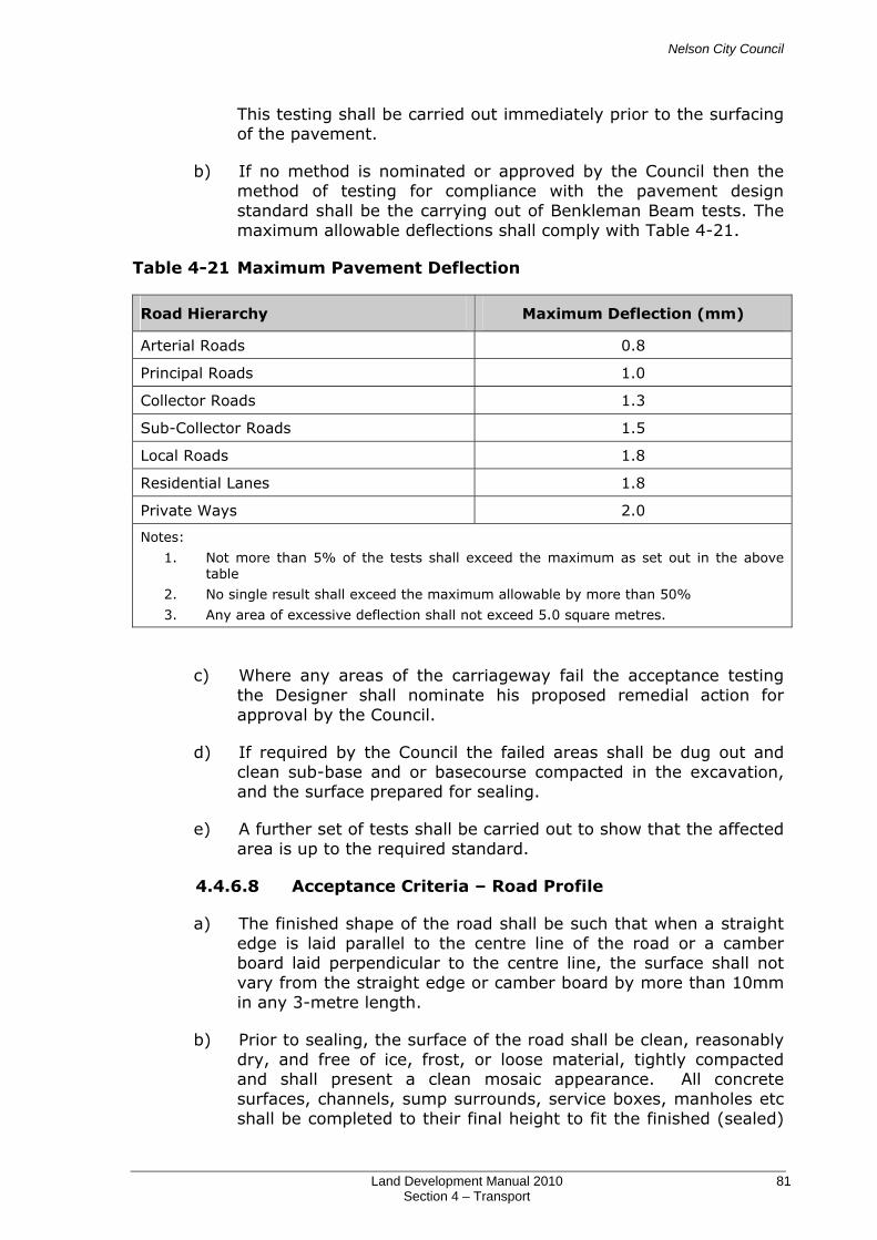
Nelson City Council
Land Development Manual 2010 81 Section 4 – Transport
This testing shall be carried out immediately prior to the surfacing of the pavement.
b) If no method is nominated or approved by the Council then the method of testing for compliance with the pavement design standard shall be the carrying out of Benkleman Beam tests. The maximum allowable deflections shall comply with Table 4-21.
Table 4-21 Maximum Pavement Deflection
Road Hierarchy Maximum Deflection (mm)
Arterial Roads 0.8
Principal Roads 1.0
Collector Roads 1.3
Sub-Collector Roads 1.5
Local Roads 1.8
Residential Lanes 1.8
Private Ways 2.0
Notes:
1. Not more than 5% of the tests shall exceed the maximum as set out in the above table
2. No single result shall exceed the maximum allowable by more than 50%
3. Any area of excessive deflection shall not exceed 5.0 square metres.
c) Where any areas of the carriageway fail the acceptance testing the Designer shall nominate his proposed remedial action for approval by the Council.
d) If required by the Council the failed areas shall be dug out and clean sub-base and or basecourse compacted in the excavation, and the surface prepared for sealing.
e) A further set of tests shall be carried out to show that the affected area is up to the required standard.
4.4.6.8 Acceptance Criteria – Road Profile
a) The finished shape of the road shall be such that when a straight edge is laid parallel to the centre line of the road or a camber board laid perpendicular to the centre line, the surface shall not vary from the straight edge or camber board by more than 10mm in any 3-metre length.
b) Prior to sealing, the surface of the road shall be clean, reasonably dry, and free of ice, frost, or loose material, tightly compacted and shall present a clean mosaic appearance. All concrete surfaces, channels, sump surrounds, service boxes, manholes etc shall be completed to their final height to fit the finished (sealed)
Nelson City Council
Land Development Manual 2010 82 Section 4 – Transport
road profile. All service boxes and manhole lids shall be finished to within 5 to 10mm above the finished (sealed) road profile.
c) The shape of the carriageway shall conform to the Camber Table, SD 420.
4.4.7 Subgrade Checking
a) Where the extent of cut or fill for the project is too great to make subgrade CBR testing feasible at the design stage it may be done on completion of earthworks when subgrade levels have been exposed. Even in cases where subgrade has been tested as part of the design its condition shall be reviewed on exposure during construction and pavement thicknesses adjusted accordingly.
b) The results of such testing and/or review along with consequent adjustments to pavement layer thicknesses shall be advised to the Council before placing of pavement layers commences.
4.4.8 Subgrade Drainage
a) This shall be a 100mm diameter or equivalent proprietary sub-soil drainage system surrounded by bedding chip.
4.4.8.1 Sub-soil Drains in Cuts (on Hillside Subdivisions)
a) When the road or right of way is in cut, a sub-soil drain shall be placed at the toe of the batter and connected into the back of the nearest sump downstream.
4.4.8.2 Wet Spots in Subgrade
a) Any permanent wet spot in the subgrade or any area undercut below adjacent sub-soil drains shall be connected to the nearest piped stormwater system by another sub-soil drain. Where the drain is located under the carriageway, traffic loading shall be taken into consideration for the type of pipe.
4.4.8.3 High Groundwater
a) In areas of high groundwater or where the road pavement design is reliant on the subgrade remaining reasonably dry, it may be necessary to install a sub-soil drainage system to prevent excessive moisture getting into to the subgrade.
4.4.8.4 Subgrade Drainage Systems
a) In some cases, it may be necessary, due to the nature of the country, to lay an extensive sub-soil drainage system. In such a case, the material covering the pipes shall be graded upwards so that particles cannot enter the pipes. In general, to satisfy the
Nelson City Council
Land Development Manual 2010 83 Section 4 – Transport
condition that particles do not enter the pipe and no scour occurs in the "filter", the following ratios must be complied with:
1) 85% size of filter material 2 Size of opening in pipe
2) 15% size of filter material 5 85% size of protected soil
3) 15% size of filter material 5 < 40 15% size of protected soil
b) It shall be necessary in most cases to manufacture a suitable filter material to comply with the above requirements.
c) Alternatively, the sub-soil drainage system may be wrapped with a Council approved filter material.
4.4.9 Carriageway Surfacing
4.4.9.1 General
a) The minimum requirement for residential streets is a wearing surface of approved two coat Grade 3 and Grade 5 chipseal or 25mm asphaltic concrete mix 10 over a Grade 5 chip seal constructed on the approved basecourse.
b) The minimum requirement for streets in industrial areas is a wearing surface of 35mm depth of mix 15 asphaltic concrete on an emulsion Grade 5 chipseal constructed on the approved basecourse. Alternative surfacing may be allowed to specific limited areas with the approval of the Council.
c) For all roundabouts, the turning heads in cul-de-sacs, and in other high stress environments the surface shall be 50mm depth of mix 15 asphaltic concrete on an emulsion Grade 5 chipseal constructed on the approved basecourse.
d) Prior to surfacing, the basecourse finish shall be such that when swept it presents a tightly compacted, non-glazed, clean stone mosaic surface that will not ravel as a result of sweeping. The standard of sweeping shall be sufficient to remove all loose aggregate, dirt, dust, silt and other deleterious matter.
4.4.9.2 Chip Seal
Seal Design
a) The seal design shall generally be the responsibility of the Designer.
b) The Designer shall submit his seal design for approval by the Council 7 days prior to any sealing commencing.

Nelson City Council
Land Development Manual 2010 84 Section 4 – Transport
c) The submitted designs shall include details of:
1) Bitumen/Emulsion to be used
2) Additives to be used
3) Application rates
4) Construction method
Sealing Binder
a) The materials used shall meet the requirements of the relevant clauses of the following NZTA specifications.
1) M/1: Roading Bitumens (2007)
2) M/13: Adhesion Agents (1989)
b) Sealing binder shall be either 180/200-penetration grade bitumen or emulsion of a suitable type from an approved supplier.
Sealing Chip
a) Sealing chip shall meet the requirements of the relevant clauses of NZTA M/6 (2004) Sealing Chip.
Application of Sealing Binder
a) Spraying operations shall be carried out so that private property and street furniture are not affected by overspray.
b) The end of each sealed area shall be a straight line at right angles to the road edge. Sealing runs should start and finish on paper and no binder shall be allowed to drip onto sections of the roadway that have previously been sealed.
Application of Chip
a) Chip spreading equipment shall be capable of spreading the aggregate evenly, at a controlled rate and in such a way that chip does not tumble on impact with the sprayed surface.
b) All excess chip shall be swept from the carriageway and removed from the channels, footpaths, berms and sumps prior to the acceptance of the works by the Council.
Acceptance Criteria
a) The two coat seal shall provide a fully interlocked surface after rolling. Chip loss, bleeding or flushing shall not exceed 5% in any one metre by one metre square of the total sealed area during the maintenance period.
Nelson City Council
Land Development Manual 2010 85 Section 4 – Transport
4.4.9.3 Asphaltic Concrete
a) For residential streets asphaltic concrete paving (hot mix) shall comply with NZTA Specification M/10 ‘Asphaltic Concrete’ (2005) Table 5.1 Mix 10 and shall be a minimum compacted thickness of 25mm. The binder shall be 80/100-penetration bitumen. The construction of the paving shall be carried out in accordance with NZTA P/9 ‘Construction of Asphaltic Concrete Paving’ (1975), unless otherwise approved by the Council.
b) For streets in industrial areas, asphaltic concrete paving (hot mix) shall comply with NZTA Specification M/10 Table 5.1 Mix 15 and shall be a minimum compacted thickness of 35mm. The binder shall be 80/100-penetration bitumen. The construction of the paving shall be carried out in accordance with NZTA P/9 ‘Construction of Asphaltic Concrete Paving’ (1975), unless otherwise approved by the Council.
c) The asphaltic concrete wearing course shall be laid on a Grade 5 chip seal constructed in accordance with Section 4.4.9.2 ‘Chip Seal’.
d) All cold asphalt joints are to be Polymer Modified Bitumen (PMB) hot bandaged. The bandage shall be at least 100mm wide and 1.5mm thick. Alternative PMB methods will be considered by Council.
e) Note that for all roundabouts and the turning heads in cul-de-sacs the surface shall be 50mm depth of Mix 15 asphaltic concrete on an emulsion Grade 5 chipseal.
4.4.9.4 Weed Protection
a) Immediately prior to any form of surfacing, a strip one metre wide adjacent to each channel shall be applied with an approved ground sterilising weed killer at the manufacturer's recommended rate of application.
4.4.10 Standards of Formation
4.4.10.1 Residential Lanes, Service Lanes and Private Ways
Formation
a) The finished surface shall have a crossfall of 1 in 33 (3%) and shaped with a crown or camber.
Metalling
a) All topsoil and growth shall be removed and compacted basecourse and sub basecourse (where required) laid and graded to an even surface.

Nelson City Council
Land Development Manual 2010 86 Section 4 – Transport
Structural Design of Pavement
a) The pavement shall be designed as detailed in Section 4.4.6 ‘Structural Design of Pavement’.
Sealing
a) All formations are to be surfaced in accordance with Section 4.4.9 ‘Carriageway Surfacing’.
Channelling
a) Kerb and channelling on Private Ways shall arise when any of the following are present:
1) The Private Way has a gradient of less than 1 in 60 (1.7%).
2) The Private Way has a length in excess of 20m.
3) Three or more potential household units served by the access.
b) Kerb and channel shall be provided on at least one side for the full length of the Private Way and the crossfall shall fall towards this.
c) For Residential Lanes, kerb and channel shall be provided on the footpath side for the full length and the crossfall shall fall towards this. A nib kerb, or similar, shall be provided on the other side for the full length of the Residential Lane.
d) For Service Lanes, kerb and channel shall be provided on both sides for the full length.
e) The high side of the formation shall be retained by either of the following: kerb and channel, nib kerb or 100mm x 25mm ground treated (H4) timber batten and 50mm x 50mm pegs.
f) The kerb and channel shall be constructed in accordance with Section 4.4.11 ‘Kerb and Channelling’.
Stormwater
a) For private ways more than 10m in length or more than 30m2 of sealed surface, all stormwater off the formation shall be collected by an approved stormwater system.
b) Sumps shall be located at the low side of the formation within kerb and channel (or similar) and at the street boundary where falls are towards the carriageway. New sumps shall not be permitted within a vehicle crossing on the line of the street kerb and channel.
Nelson City Council
Land Development Manual 2010 87 Section 4 – Transport
4.4.10.2 Commercial and Industrial Areas
a) Service Lanes in commercial and industrial areas shall be formed as for streets; see Section 4.4.6 ‘Structural Design of Pavement’ and Section 4.4.9 ‘Carriageway Surfacing’.
b) Kerb and channel and stormwater drainage shall be provided.
4.4.11 Kerbing and Channelling
a) Kerb and channel should be provided on both sides of the carriageway except for carriageways with single crossfall such as private ways and residential lanes.
4.4.11.1 Excavation and Basecourse
a) If unsuitable soil conditions are encountered at the base of kerb and channel excavations the site shall be trenched out below this depth and backfilled with gravel or other approved fill material in layers of a thickness that is compatible with the type of compaction equipment and material being used. Compaction shall be to a minimum of 98% of maximum dry density. A minimum depth of 50mm of compacted base course shall be placed under the kerb and channel.
4.4.11.2 Concrete
a) All concrete shall be mixed using separately graded fine and coarse aggregates in a power-driven weight batch mixer, or it may be supplied by an approved "ready mix" concrete works. In either case, the concrete shall comply with specified requirements of High Grade Concrete in NZS 3108: 1983 ‘Specification for concrete production – ordinary grade’ that is, have a minimum cement content of 362kg per cubic metre and a maximum water/cement ratio of 0.52, giving a minimum specified crushing strength at 28 days standard cured of 28 MPa.
b) Construction joints to control cracking shall be installed in the kerb and channel every 6 – 8m.
4.4.11.3 Formwork
a) Slip forming of the kerb and channel is generally acceptable provided the standard of work produced by an individual machine has been approved by the Council.
b) Formwork for kerb and channel shall be approved dressed timber, steel or aluminium alloy sections adequately oiled or otherwise treated to allow ease of striking without staining of the stripped concrete surface. All formwork shall be accurately placed to the lines and levels of the works and shall be such as to give the finished kerbs smooth and pleasing lines free of kinks and angles.
Nelson City Council
Land Development Manual 2010 88 Section 4 – Transport
c) The profile shall conform with SD 407 and the finish and accuracy of the work comply with that stated in Section 4.4.11.4 ‘Accuracy and Standard of Workmanship’.
4.4.11.4 Accuracy and Standard of Workmanship
a) Construction joints (for crack control) shall be installed at 6.0m intervals. Kerbs and channels shall be finished such that on straight portions there is no deviation of more than 5mm within the length of a 3m straight edge; nor a deviation of more than 5mm from the line and level.
b) Kerbing and channelling be finished with a steel float and any concrete work showing honeycombing or scale in the face is to be removed and replaced with fresh concrete of the grade specified in Section 4.4.11.2 ‘Concrete’.
c) All repairs to damaged kerb must be made prior to footpath surfacing.
4.4.11.5 Curves
a) The Council may direct that horizontal or vertical curves of less than 60m radius shall be constructed using special insitu formwork.
b) Use of regular forms to produce a chorded effect shall not be accepted.
c) Changes of grade shall be made with a smooth vertical curve, and horizontal curves shall be true.
4.4.11.6 Benchmarks
a) The Designer shall install NCC standard benchmark plaques on the top of the kerb. A minimum of one plaque shall be installed in each new street, at maximum intervals of 300m. Where a plaque is installed to meet the requirement of Land Information NZ (LINZ) this shall be used as the benchmark and the NCC plaque omitted.
b) The proposed location shall be shown on the engineering plans. The Designer shall establish a reduced level and coordinates on each new benchmark and show this on the "As Built" plans to two decimal places. The origin for the levels shall be from a previously established benchmark, and the origin stated on the drawings. A closed circuit run shall be used to establish each new benchmark level. The coordinates shall be established to Fourth Order survey standard accuracy.
c) The levelling shall be carried out to second order standards and levels are to be shown to two decimal places.

Nelson City Council
Land Development Manual 2010 89 Section 4 – Transport
d) Where a subdivision is staged the Designer may not be required to install a benchmark in each stage.
e) NCC benchmark plaques will be supplied by the Council at no cost to the Designer.
4.4.12 Footpaths
a) The following construction standards apply to footpaths and paths in roads, accessway links between roads, accessways linking roads to reserves and paths in reserves.
b) Footpaths and accessways must have a durable and non-skid surface.
c) The surface may be concrete, asphaltic concrete or block paving where specifically approved by the Council.
d) Where a footpath is constructed and there is a mountable kerb, both shall be designed to carry the same vehicle loadings as the carriageway. Refer to 4.4.14 Kerb Crossings.
e) The footpath pavement shall be designed in accordance with recognised techniques that include but are not limited to those listed below.
1) CBR Method (CBR Design curves are given on SD 405).
2) Scala/Dynamic Cone Penetrometer (Design curves are given on SD 406).
f) Shared accessway and footpath construction must be continuous across driveways to ensure priority of shared accessway or footpath users is reinforced.
4.4.12.1 Concrete Footpaths
a) The minimum construction is to be 100mm thickness of 25MPa at 28 days concrete. The finish shall be wooden float, or other equivalent non-skid surface.
b) Residential entrance slabs shall be increased to a minimum of 150mm thick for full width of crossing including wings.
c) Commercial entrance slabs shall have a minimum of 200mm thickness of 30MPa concrete and shall be reinforced with one layer of 665 wwf placed 50mm from bottom edge of concrete.
d) Industrial entrance slabs shall have a minimum thickness of 300mm of 30MPa concrete and shall be reinforced with 2 layers of 665 WWF reinforcing mesh. The 2 layers of mesh shall be placed 200mm apart with each layer having 50mm cover from the outside surface of the concrete.

Nelson City Council
Land Development Manual 2010 90 Section 4 – Transport
e) Construction joints are required at 6m intervals, and on both sides of entrance slabs. Refer to 409 for full details
4.4.12.2 Asphaltic Concrete Footpaths
a) The path shall be paved with 25mm compacted depth of asphaltic concrete (refer NZTA M/10 Mix 10). All areas to be paved must be tack-coated prior to paving.
b) A ground treated (H4) timber batten 100mm x 25mm minimum shall be firmly pegged along the edges of the footpath with the top of the batten at finished level, and shall remain intact after the completion of the work. Refer to 410.
c) Joints in the asphalt surfacing shall be either saw cut or formed to produce a neat straight line at right angles to the edge of the footpath and a flush smooth finish to the surface of the footpath. Joints shall have a tack coat applied.
d) The compacted basecourse depth shall be a minimum depth of 150mm on a subgrade with a minimum CBR of 6.
e) Commercial and Industrial entrances shall be designed to take the same traffic loadings as the carriageway. Refer to SD 410 for full details.
4.4.12.3 Acceptance Criteria
a) At no point on the finished basecourse surface shall the Clegg Impact Value be less than 25 for footpaths and residential crossings, and 35 for commercial vehicle crossings.
b) The surface of the finished footpath shall be such that when a 3m long straight edge is placed across the footpath no area deviates from the straight edge by more than 5mm. The edge of the footpath shall not deviate by more than 5mm from the line and levels shown on the approved Engineering Drawings.
c) Where adjacent to a kerb, the surface of the footpath shall be flush with or no more than 5mm above the top of the kerb.
4.4.12.4 Handrail
a) Where located adjacent to public roads accessible by a motor vehicle, the handrail shall comply with Juralco Viking Balustrade (full height baluster) design, or other similar approved design as in SD 425.
b) In other environments, such as ‘Accessways’, the handrail may comply with the alternative design as in SD 424.
c) If the designer wishes to erect a fence or handrail of alternative design to the two above, then full details shall be submitted to the Council for approval.
Nelson City Council
Land Development Manual 2010 91 Section 4 – Transport
4.4.13 Retaining Walls
a) A building consent shall be obtained for all retaining structures retaining more than 1.5m depth of ground and/or supporting a surcharge.
b) All retaining structures on Council land and structures that will be vested in Council ownership shall have a design life of 80 years minimum. The design an construction shall be supervised by a Chartered Professional Engineer.
c) To improve visual amenity, retaining walls shall be of the minimum height necessary. Also, where possible and practical, retaining walls shall be constructed in such a manner as to allow planting in the wall or in front of the wall.
d) The design of all retaining structures supporting roads, ROW’s, footpaths or areas likely to have buildings erected within the area between the wall and a line measured at 45 degrees to horizontal from the base of the wall, shall include specific information from the Designer’s Professional Advisor (DPA) stating what design and construction methods will be implemented to ensure that future settlement of the ground behind the wall and the ground surface will be no greater than 20mm over a 6m horizontal length.
e) Generally retaining walls shall be constructed of either (or a combination) of the following types:
1) Concrete Tilt slab
2) Timber Pole (or Steel) with Timber rail
3) Concrete Crib
4) Galvanised Mesh Gabion
f) Mechanically Stabilised Earth, Timber Crib or Rock walls are subject to specific design approval by Council.
4.4.13.1 Drainage of Retaining Walls
a) Sub-soil drainage is not a general requirement for a permeable retaining wall such as a crib wall or timber pole wall. There are situations where sub-soil drainage of permeable walls may be required:
1) Where walls have a back sloping below ground footing where water may be trapped.
2) Where seepage from a retaining wall may cause a nuisance to an adjoining property owner.

Nelson City Council
Land Development Manual 2010 92 Section 4 – Transport
3) Where seepage from a retaining wall in close proximity to a building site may be a nuisance or unsightly.
4) Where a retaining wall is being built in an area of suspect stability and the removal of surface / ground water would be an advantage.
b) Where subsoil drains are required, a subsoil drain comprising 110mm diameter Novaflow pipe shall be provided behind all walls. Subsoil drains shall be surrounded with 100mm minimum of free draining drainage metal. Drains shall be excavated into firm ground below the base of the wall and shall be linked together and extended to connect into an approved stormwater system.
c) Approved filter fabric material shall be placed between the drainage metal and in-situ or fill material.
4.4.14 Kerb and Swale Drain Crossings
a) Kerb crossings shall be designed and constructed in accordance with SD 408 and 412.
b) The minimum diameter of culverts under driveways where the driveway crosses the road swale drain shall be 300mm diameter.
4.4.15 Berms
a) After the construction of the road and footpaths, and the installation of all services has been completed, the berm surfaces not occupied by pavements shall be levelled or graded to conform to the pavement edges and the adjoining properties, so far as is practical, allowing for the addition of topsoil to final grade.
b) Topsoil to a firm minimum thickness of 100mm on clay surfaces and 150mm on sandy or gravely surfaces shall then be spread so that a smoothly contoured surface is produced, free of ponding areas. The subgrade shall be capable of allowing root penetration and sustaining growth.
c) The final topsoil surface shall be flush with the adjacent kerb and footpath and sown with approved seed mixtures. Special soils or conditions shall be treated to Council approval.
4.4.15.1 Grassing
a) After topsoiling, the berms shall be sown with grass seed that conforms to the following mix proportions:
1) 1.0kg chewing fescue
2) 4.5kg dwarf rye grass

Nelson City Council
Land Development Manual 2010 93 Section 4 – Transport
3) 0.5kg browntop
b) The mixture shall be sown at a rate of 1kg to 40 square metres area.
c) Prior to the sowing of the grass seed, fertiliser shall be spread and mixed with the topsoil. The recommended fertiliser is Super Phosphate applied at a rate of 30g per square metre. Alternative fertiliser and application rates may be used subject to prior consultation with the Council
d) After two months dressing with Super Phosphate, a dressing with Sulphate of Ammonia applied at a rate of 30g per square metre shall be applied.
4.4.15.2 Street Trees
a) Species are to be selected in accordance with Council’s ‘Street Tree Guidelines 2009’. All plants used shall be healthy vigorous and free of any defects that may be detrimental to plant growth and development. Council requires the use of locally sourced native species where appropriate.
b) The trees shall be provided with root guards to prevent root damage to adjoining paved surfaces see SD 1201 and 1202. No trees or shrubs shall be planted within a 2.0m radius of any water valve or hydrant.
c) Street trees planted within services free pavement areas of the inner city or commercial areas shall be provided in accordance with planter detail in SD 1202 and be protected by a tree guard.
4.4.15.3 Alternatives to Grassed Berms
Stone Surface
a) This shall be crushed stone, uniformly graded with a nominal diameter of 20mm. The depth of the stone layer shall be 100mm. Crushed stone provides a considerably more suitable surface for walking compared to a round stone surface.
b) Prior to placing the stone the excavated surface shall be compacted and a layer of weed cloth installed.
c) The finished stone surface shall be uniform without any hollows or ridges and be flush with the top of the kerb and edge of footpath.
Ornamental Ground Cover
d) The five varieties approved for use are:
1) Purple Haze (Acacena Inermis Purpureum)
2) Kina Red Heads (Acaena Inermis)

Nelson City Council
Land Development Manual 2010 94 Section 4 – Transport
3) Bronze Feather Carpet (Leptinella Trailii)
4) Mazus Radicans
5) Mercury Bay (Dichondra)
e) Planting shall be to the requirements of the plant retailer. The finished surface shall be uniform without any hollows or ridges and be flush with the top of the kerb and edge of footpath.
4.4.16 Road Marking
a) All new edge lines, centrelines, continuity lines and limit lines shall be reflectorised with Type C glass beads to AS/NZS 2009: 2006 ‘Glass beads for pavement-marking materials’ applied at 225g/m2 and 220µm dry film thickness. A second coat is required after 6-8 months. A water based paint may be used for the second coat in these situations.
b) Water based paint may be used for all other types of road marking, except, where road markings are required on any surface that is not chip seal or asphaltic concrete, in which case thermoplastic materials must be used.
4.4.17 Signage
a) The location of all signs shall be shown on the Engineering Plans for approval by Council.
b) All signs shall be installed by a contractor approved by Nelson City Council. The Developer shall liaise directly with the contractor regarding this work and all costs shall be met by the Developer.
c) If the Designer wishes to incorporate special signs these shall be in addition to the standard nameplate, and be subject to specific approval by the Council. Supply and erection of any special signs shall be the responsibility of the Developer.
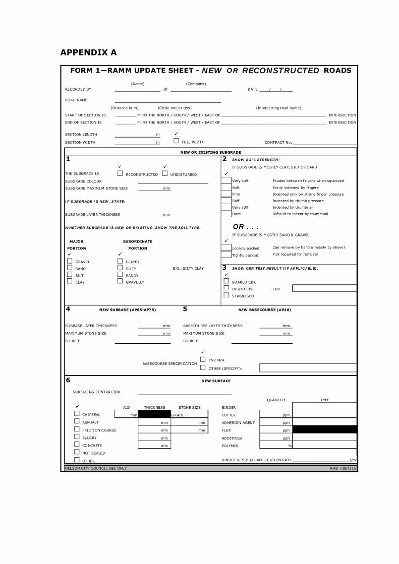
APPENDIX A
FORM 1—RAMM UPDATE SHEET - NEW OR RECONSTRUCTED ROADS
(Name) (Company)
RECORDED BY OF DATE / /
ROAD NAME
(Distance in m) (Circle one or two) (Intersecting road name)
START OF SECTION IS _________ m TO THE NORTH / SOUTH / WEST / EAST OF ______________________________________________ INTERSECTION
END OF SECTION IS _________ m TO THE NORTH / SOUTH / WEST / EAST OF ______________________________________________ INTERSECTION
SECTION LENGTH m
SECTION WIDTH m FULL WIDTH CONTRACT No.
NEW OR EXISTING SUBGRADE
1 2 SHOW SOIL STRENGTH:
IF SUBGRADE IS MOSTLY CLAY, SILT OR SAND:
THE SUBGRADE IS RECONSTRUCTED UNDISTURBED SUBGRADE COLOUR Very soft Exudes between fingers when squeezed
SUBGRADE MAXIMUM STONE SIZE mm Soft Easily indented by fingers
Firm Indented only by strong finger pressure
IF SUBGRADE IS NEW, STATE: Stiff Indented by thumb pressure
Very stiff Indented by thumbnail
SUBGRADE LAYER THICKNESS mm Hard Difficult to indent by thumbnail
WHETHER SUBGRADE IS NEW OR EXISTING, SHOW THE SOIL TYPE: OR . . . IF SUBGRADE IS MOSTLY SAND & GRAVEL:
MAJOR SUBORDINATE PORTION PORTION Loosely packed
Tightly packed
GRAVEL CLAYEY
SAND SILTY E.G., SILTY CLAY 3 SHOW CBR TEST RESULT (IF APPLICABLE):
SILT SANDY CLAY GRAVELLY SOAKED CBR
INSITU CBR CBR
STABILISED
4 NEW SUBBASE (AP65-AP75) 5 NEW BASECOURSE (AP40)
SUBBASE LAYER THICKNESS mm BASECOURSE LAYER THICKNESS mm
MAXIMUM STONE SIZE mm MAXIMUM STONE SIZE mm
SOURCE SOURCE
TNZ M/4
OTHER (SPECIFY):
SURFACING CONTRACTOR
QUANTITY TYPE
ALD THICKNESS STONE SIZE BINDER
CHIPSEAL mm GRADE CUTTER pph
ASPHALT mm mm ADHESION AGENT pph
FRICTION COURSE mm mm FLUX pph
SLURRY mm ADDITIVES pph
CONCRETE mm POLYMER %
NOT SEALED
OTHER BINDER RESIDUAL APPLICATION RATE _________________________l/m2
NELSON CITY COUNCIL USE ONLY RAD_n867318
6 NEW SURFACE
Pick required for removal
Can remove by hand or easily by shovel
BASECOURSE SPECIFICATION


![BANGALORE METROPOLITAN TRANSPORT …...1 BANGALORE METROPOLITAN TRANSPORT CORPORATION RTI UNDER [Section 4(1) B] CHAPTER-16 PERSONNEL DEPARTMENT Information about the Public Information](https://static.fdocuments.us/doc/165x107/5e73911ea9d9e6018977d59e/bangalore-metropolitan-transport-1-bangalore-metropolitan-transport-corporation.jpg)


