Contents Safety First - s3-eu-west-1.amazonaws.com · youngmangroup.com BoSS Ladderspan...
9
USER GUIDE Edition : August 2010 BoSS Ladderspan incorporating BoSS Cam-Lock Advance Guardrail Mobile aluminium tower with 1450/850 frames 1 BoSS Ladderspan incorporating BoSS Cam-Lock Advance Guardrail User Guide Contents 2 youngmangroup.com Safety First Please read this guide carefully. Please note that diagrams are for illustrative purposes only. User guides are also available to download from our website at youngmangroup.com BoSS mobile aluminium towers are light-weight scaffold towers used throughout the building and construction industry for both indoor and outdoor access solutions where a stable and secure platform is required. Ideal for maintenance and installation work or short-term access, the highly versatile towers provide a strong working platform for a variety of heights. This User Guide provides you with step by step instructions to ensure your system is erected easily and safely, using the AGR (Advance Guard Rail) method. The law requires that personnel erecting, dismantling or altering towers must be competent. Any person erecting a Youngman BoSS mobile tower must have a copy of this guide. For further information on the use of mobile access and working towers consult the PASMA operators code of practice. If you need further information, design advice, additional guides or any other help with this product, please contact Youngman on +44 (0)1621 745900 email us at [email protected] or you can visit www. youngmangroup.com to download further information. COMPLIANCES The BoSS Ladderspan aluminium system has been designed, tested, approved and certified to EN 1004: 2004 Class 3 Instruction Manual EN 1298-IM-EN PREPARATION AND INSPECTION Inspect the equipment before use to ensure that it is not damaged and that it functions properly. Damaged or incorrect components shall not be used. INTRODUCTION Safety First 2 Safety Checklist 8 Quantity Schedules 9 Assembly and Dismantling Procedure 15 Toeboards 23 Stabilisers and Outriggers 24
Transcript of Contents Safety First - s3-eu-west-1.amazonaws.com · youngmangroup.com BoSS Ladderspan...

USER GUIDEEdition : August 2010
BoSS Ladderspan incorporating
BoSS Cam-Lock Advance Guardrail
Mobile aluminium tower with 1450/850 frames
1 BoSS Ladderspan incorporating BoSS Cam-Lock Advance Guardrail User Guide
Contents
2 youngmangroup.com
Safety First
Please read this guide carefully.Please note that diagrams are for illustrative purposes only.User guides are also available to download from our website at youngmangroup.com
BoSS mobile aluminium towers are light-weight scaffold towers used throughout the building and construction industry for both indoor and outdoor access solutions where a stable and secure platform is required. Ideal for maintenance and installation work or short-term access, the highly versatile towers provide a strong working platform for a variety of heights.
This User Guide provides you with step by step instructions to ensure your system is erected easily and safely, using the AGR (Advance Guard Rail) method.
The law requires that personnel erecting, dismantling or altering towers must be competent. Any person erecting a Youngman BoSS mobile tower must have a copy of this guide. For further information on the use of mobile access and working towers consult the PASMA operators code of practice.
If you need further information, design advice, additional guides or any other help with this product, please contact Youngman on +44 (0)1621 745900 email us at [email protected] or you can visit www.youngmangroup.com to download further information.
COMPLIANCES
The BoSS Ladderspan aluminium system has been designed, tested, approved and certified to EN 1004: 2004 Class 3
Instruction Manual EN 1298-IM-EN
PREPARATION AND INSPECTION
Inspect the equipment before use to ensure that it is notdamaged and that it functions properly. Damaged or incorrectcomponents shall not be used.
INTRODUCTION Safety First 2
Safety Checklist 8
Quantity Schedules 9
Assembly and Dismantling Procedure 15
Toeboards 23
Stabilisers and Outriggers 24

3 BoSS Ladderspan incorporating BoSS Cam-Lock Advance Guardrail User Guide 4youngmangroup.com
Check that all components are on site, undamaged and that they are functioning correctly – (refer to Checklist and Quantity Schedules in the user guide). Damaged or incorrect components shall not be used.
Check ground on which tower is to be erected and moved is capable of supporting the tower.
The safe working load is 275 kgs (606lbs), per platform level, uniformly distributed up to a maximum of 950kgs (2100lbs), per tower (including self weight).
Towers must only ever be climbed from the inside and using the ladder directly below the trap door
It is recommended that towers should be tied to a solidstructure when left unattended.
Only use the adjustable legs to level the tower and not to gain extra height. Adjustable legs should only ever be extended to minimum amount required to level the tower.
LIFTING OF EQUIPMENT
Tower components should be lifted using a reliable liftingmaterial (e.g. strong rope), employing a reliable knot (e.g. clove hitch), to ensure safe fastening and always lift within the footprint of the tower.
Assembled mobile towers should not be lifted with a crane or other lifting device.
Safety First SAFE USE
Stabilisers or outriggers and ballast weights shall always be fitted when specified.
The Quantity Schedules show the recommended stabilisation. In circumstances where there is restricted ground clearance for stabilisers/outriggers, contact your supplier for advice. Ballast must be of solid materials (i.e. not water or loose sand) and should not be positioned to overload individual legs. Ballast should be secured against accidental removal where practicable, and be placed on an appropriate platform positioned on the lowest rung of the bottom frame
Safety FirstSTABILISERS / BALLAST
Movement of the tower is strictly prohibited if any material, equipment or persons are on any of the platforms
Check that the route of movement is clear and free from obstacles, hazards* or voids and the floor is capable of supporting the weight of the tower
Do not move any tower structure in wind speeds over 7.7m per second (17mph). See page 5 of this user guide for wind speed guidance
Dismantle the tower to a maximum height of 4m If stabilisers are fitted, raise them a maximum of 25mm above
ground level (to clear uneven ground) and clamp tight. Check that the tower structure is secure and safe to move. Restrain the tower from unintentional movement and unlock all
four castors. Move tower using manual effort only, applied at the base. Re-lock all four castors and re-position stabilisers (if fitted) as
per this user guide. Using a spirit level, check tower is level and vertical as in step
4, setting the adjustable legs as required. Do not use adjustable legs to increase the overall height of the
tower. Rebuild the tower (by competent person) to the intended
working height. Inspect completed tower (by competent person) and record
inspection.
NOTE: The work at height recomendations (reg 12 (2)) require that where the safety of work and equipment depends on how it is installed or assembled, it is not used after installation or assembly in any position unless it has been inspected in that position.
* Include electrical hazards, moving machinery, access restrictions, overhead cables etc.
Movement
5 BoSS Ladderspan incorporating BoSS Cam-Lock Advance Guardrail User Guide
Beware of high winds in exposed, gusty or medium breeze conditions. We recommend that in wind speeds over 7.7 metres per second (17 mph), cease working on the tower and do not attempt to move it. If the wind becomes a strong breeze, expected to reach 11.3 metres per second (25 mph), tie the tower to a rigid structure. If the wind is likely to reach gale force, over 18 metres per second (40 mph), the tower should be dismantled.
Wind Description
Beaufort Scale Beaufort No.
Speed in m.p.h
Speed in m/sec
Medium Breeze
Raises dust and loose paper,twigs snap off
4 8-12 4-6
Strong Breeze
Large branches in motion, telegraph wires whistle
6 25-31 11-14
Gale Force Walking is difficult 8 39-46 17-21
Beware of open ended buildings, which can cause funnelling effect.
Do not abuse equipment. Damaged or incorrect components shall not be used.
Raising and lowering components, tools, and/or materials by rope should be conducted within the tower base. Ensure that the safe working load of the supporting decks and the tower structure is not exceeded.
The assembled tower is a working platform and should not be used as a means of access or egress to other structures.
Beware of horizontal forces (e.g. power tools) which could generate instability. Maximum horizontal force 20 kg.
The stairway towers, featuring an inclined staircase access, are for frequent use by personnel carrying tools and/or materials.
Mobile towers are not designed to be suspended - pleaserefer to your supplier for advice.
Do not use boxes or stepladders or other objects on theplatform to gain extra height.
DURING USE
Safety First

6 youngmangroup.com
Ties should be used when the tower goes beyond its safe height, beyond the limits of the stabilisers/outriggers, or if there is a danger of instability. They should be rigid, two way ties fastened to both uprights of the frame with load-bearing right angled or swivel couplers. Only couplers suitable for the 50.8mm diameter tube of the tower should be used. Ideally, ties should be secured to both faces of a solid structure by means of anchorages.
The tie frequency may vary depending on the application, but they should, at a minimum, be every 4 metres height.
For further information on tying-in a tower please contact your supplier or Youngman.
MAINTENANCE - STORAGE - TRANSPORT
All components and their parts should be regularly inspected to identify damage, particularly to joints. Lost or broken parts should be replaced, and any tubing with indentation greater than 5mm should not be used and put to one side for repair by the manufacturer. Adjustable leg threads should be cleaned and lightly lubricated to keep them free running.
Brace claws, frame interlock clips, trapdoor latches andplatform windlocks should be regularly checked to ensure they lock correctly.
Refer to the BoSS Inspection Manual and poster for detailed inspection and maintenance advice
Components should be stored with due care to preventdamage.
Ensure components are not damaged by excessive strapping forces when transported.
Safety First TIES
7 BoSS Ladderspan incorporating BoSS Cam-Lock Advance Guardrail User Guide
Safety First Safety ChecklistMobile Towers - AGR Method CHECKLIST
8
Ensure all brace claws & cam locks operate and lock correctly prior to erection
Inspect components prior to erection
Inspect tower prior to use and after movement and as required by current legislation
Tower upright and level
Castors locked and legs correctly adjusted
Diagonal braces fitted
Stabilisers/outriggers fitted as specified
Platforms located and windlocks on
Toeboards located
Check guardrails are fitted correctly. See illustration below.
Ensure horizontal braces and guardrails are fitted correctly.Always fit as shown.
Refer to this checklist before using each time.
End Toeboard
BoSS Cam-Lock Advance Guardrail Frame
Side Toeboard
Adjustable Leg
2 Rung Ladder Frame
Castor
4 Rung Span Frame
Stabiliser
Trap Door Deck
Fixed Deck
2 Rung Span Frame
4 Rung Ladder Frame
Horizontal Brace
Diagonal Brace
youngmangroup.com
BoSS Ladderspan incorporating BoSS Cam-Lock Advance Guardrail User Guide
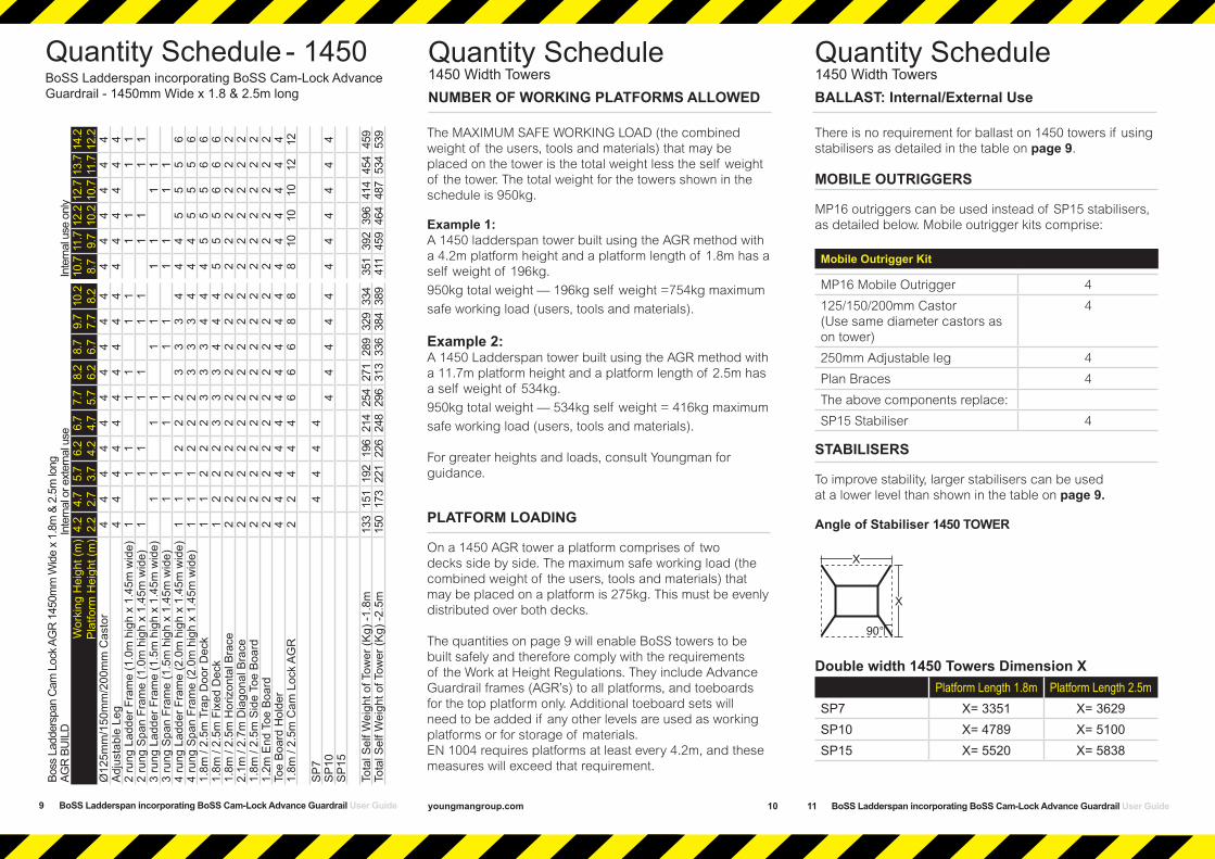
Quantity Schedule - 1450
9
BoSS Ladderspan incorporating BoSS Cam-Lock Advance Guardrail - 1450mm Wide x 1.8 & 2.5m long
Boss
Lad
ders
pan
Cam
Loc
k AG
R 1
450m
m W
ide
x 1.
8m &
2.5
m lo
ng
AGR
BU
ILD
In
tern
al o
r ext
erna
l use
In
tern
al u
se o
nly
Wor
king
Hei
ght (
m)
Pla
tform
Hei
ght (
m)
4.2
2.2
4.7
2.7
5.7
3.7
6.2
4.2
6.7
4.7
7.7
5.7
8.2
6.2
8.7
6.7
9.7
7.7
10.2
8.
2 10
.7
8.7
11.7
9.
7 12
.2
10.2
12.7
10
.7 13
.7
11.7
14.2
12
.2
Ø12
5mm
/150
mm
/200
mm
Cas
tor
4 4
4 4
4 4
4 4
4 4
4 4
4 4
4 4
Adj
usta
ble
Leg
4 4
4 4
4 4
4 4
4 4
4 4
4 4
4 4
2 ru
ng L
adde
r Fra
me
(1.0
m h
igh
x 1.
45m
wid
e)
1 1
1 1
1 1
1 1
1 1
1 2
rung
Spa
n Fr
ame
(1.0
m h
igh
x 1.
45m
wid
e)
1 1
1 1
1 1
1 1
1 1
1 3
rung
Lad
der F
ram
e (1
.5m
hig
h x
1.45
m w
ide)
1
1 1
1 1
1 1
1 1
1 3
rung
Spa
n Fr
ame
(1.5
m h
igh
x 1.
45m
wid
e)
1 1
1 1
1 1
1 1
1 1
4 ru
ng L
adde
r Fra
me
(2.0
m h
igh
x 1.
45m
wid
e)
1 1
1 2
2 2
3 3
3 4
4 4
5 5
5 6
4 ru
ng S
pan
Fram
e (2
.0m
hig
h x
1.45
m w
ide)
1
1 1
2 2
2 3
3 3
4 4
4 5
5 5
6 1.
8m /
2.5m
Tra
p D
oor D
eck
1 1
2 2
2 3
3 3
4 4
4 5
5 5
6 6
1.8m
/ 2.
5m F
ixed
Dec
k 1
2 2
2 3
3 3
4 4
4 5
5 5
6 6
6 1.
8m /
2.5m
Hor
izon
tal B
race
2
2 2
2 2
2 2
2 2
2 2
2 2
2 2
2 2.
1m /
2.7m
Dia
gona
l Bra
ce
2 2
2 2
2 2
2 2
2 2
2 2
2 2
2 2
1.8m
/ 2.
5m S
ide
Toe
Boa
rd
2 2
2 2
2 2
2 2
2 2
2 2
2 2
2 2
1.2m
End
Toe
Boa
rd
2 2
2 2
2 2
2 2
2 2
2 2
2 2
2 2
Toe
Boa
rd H
olde
r 4
4 4
4 4
4 4
4 4
4 4
4 4
4 4
4 1.
8m /
2.5m
Cam
Loc
k A
GR
2
2 4
4 4
6 6
6 8
8 8
10
10
10
12
12
SP
7
4 4
4 4
SP
10
4 4
4 4
4 4
4 4
4 4
4 S
P15
Tota
l Sel
f Wei
ght o
f Tow
er (K
g) -1
.8m
13
3 15
1 19
2 19
6 21
4 25
4 27
1 28
9 32
9 33
4 35
1 39
2 39
6 41
4 45
4 45
9 To
tal S
elf W
eigh
t of T
ower
(Kg)
-2.5
m
150
173
221
226
248
296
313
336
384
389
411
459
464
487
534
539
10 youngmangroup.com
Quantity Schedule1450 Width Towers
The MAXIMUM SAFE WORKING LOAD (the combined weight of the users, tools and materials) that may be placed on the tower is the total weight less the self weight of the tower. The total weight for the towers shown in the schedule is 950kg.
Example 1:A 1450 ladderspan tower built using the AGR method with a 4.2m platform height and a platform length of 1.8m has a self weight of 196kg.
950kg total weight — 196kg self weight =754kg maximum
safe working load (users, tools and materials).
Example 2:A 1450 Ladderspan tower built using the AGR method with a 11.7m platform height and a platform length of 2.5m has a self weight of 534kg.
950kg total weight — 534kg self weight = 416kg maximum
safe working load (users, tools and materials).
For greater heights and loads, consult Youngman for guidance.
PLATFORM LOADING
On a 1450 AGR tower a platform comprises of two decks side by side. The maximum safe working load (the combined weight of the users, tools and materials) that may be placed on a platform is 275kg. This must be evenly distributed over both decks.
The quantities on page 9 will enable BoSS towers to be built safely and therefore comply with the requirements of the Work at Height Regulations. They include Advance Guardrail frames (AGR’s) to all platforms, and toeboards for the top platform only. Additional toeboard sets will need to be added if any other levels are used as working platforms or for storage of materials. EN 1004 requires platforms at least every 4.2m, and these measures will exceed that requirement.
NUMBER OF WORKING PLATFORMS ALLOWED
11 BoSS Ladderspan incorporating BoSS Cam-Lock Advance Guardrail User Guide
There is no requirement for ballast on 1450 towers if usingstabilisers as detailed in the table on page 9.
MOBILE OUTRIGGERS
MP16 outriggers can be used instead of SP15 stabilisers, as detailed below. Mobile outrigger kits comprise:
Mobile Outrigger Kit
MP16 Mobile Outrigger 4
125/150/200mm Castor (Use same diameter castors as on tower)
4
250mm Adjustable leg 4
Plan Braces 4
The above components replace:
SP15 Stabiliser 4
STABILISERS
To improve stability, larger stabilisers can be usedat a lower level than shown in the table on page 9.
Angle of Stabiliser 1450 TOWER
Double width 1450 Towers Dimension X Platform Length 1.8m Platform Length 2.5m
SP7 X= 3351 X= 3629SP10 X= 4789 X= 5100SP15 X= 5520 X= 5838
Quantity Schedule1450 Width TowersBALLAST: Internal/External Use
X
X
90°

12youngmangroup.com
Quantity Schedule - 850BoSS Ladderspan incorporating BoSS Cam-Lock Advance Guardrail - 850mm Wide x 1.8 & 2.5m long
Boss
Lad
ders
pan
Cam
-Loc
k AG
R 8
50m
m W
ide
x 1.
8m &
2.5
m lo
ng
AGR
BU
ILD
In
tern
al o
r ext
erna
l use
In
tern
al u
se o
nly
Wor
king
Hei
ght (
m)
Plat
form
Hei
ght (
m)
4.2
2.2
4.7
2.7
5.7
3.7
6.2
4.2
6.7
4.7
7.7
5.7
8.2
6.2
8.7
6.7
9.7
7.7
10.2
8.
2 10
.7
8.7
11.7
9.
7 12
.2
10.2
12.7
10
.7 13
.7
11.7
14.2
12
.2
Ø12
5mm
/150
mm
/200
mm
Cas
tor
4 4
4 4
4 4
4 4
4 4
4 4
4 4
4 4
Adj
usta
ble
Leg
4 4
4 4
4 4
4 4
4 4
4 4
4 4
4 4
2 ru
ng L
adde
r Fra
me
(1.0
m h
igh
x 0.
85m
wid
e)
1
1 1
1
1
1 1
1
1
1 1
2 ru
ng S
pan
Fram
e (1
.0m
hig
h x
0.85
m w
ide)
1
1 1
1 1
1 1
1 1
1
1 3
rung
Lad
der F
ram
e (1
.5m
hig
h x
0.85
m w
ide)
1
1 1
1 1
1 1
1 1
1 3
rung
Spa
n Fr
ame
(1.5
m h
igh
x 0.
85m
wid
e)
1 1
1 1
1 1
1 1
1 1
4 ru
ng L
adde
r Fra
me
(2.0
m h
igh
x 0.
85m
wid
e)
1 1
1 2
2 2
3 3
3 4
4 4
5 5
5 6
4 ru
ng S
pan
Fram
e (2
.0m
hig
h x
0.85
m w
ide)
1
1 1
2 2
2 3
3 3
4 4
4 5
5 5
6 1.
8m /
2.5m
Tra
p D
oor D
eck
1 2
2 2
3 3
3 4
4 4
5 5
5 6
6 6
1.8m
/ 2.
5m H
oriz
onta
l Bra
ce
2 2
2 2
2 2
2 2
2 2
2 2
2 2
2 2
2.1m
/ 2.
7m D
iago
nal B
race
2
2 2
2 2
2 2
2 2
2 2
2 2
2 2
2 1.
8m /
2.5m
Sid
e To
e B
oard
2
2 2
2 2
2 2
2 2
2 2
2 2
2 2
2 0.
6m E
nd T
oe B
oard
2
2 2
2 2
2 2
2 2
2 2
2 2
2 2
2 To
e B
oard
Hol
der
4 4
4 4
4 4
4 4
4 4
4 4
4 4
4 4
1.8m
/ 2.
5m C
am L
ock
AG
R
2 2
4 4
4 6
6 6
8 8
8 10
10
10
12
12
SP
7 4
4 4
4 4
SP
10
4 4
4 4
4 4
4 4
4 4
SP
15
4
Tota
l Sel
f Wei
ght o
f Tow
er (K
g) -
1.8m
11
3 13
1 15
5 15
9 17
7 21
3 21
7 23
5 25
9 27
8 28
1 30
5 30
9 32
7 35
1 35
5 To
tal S
elf W
eigh
t of T
ower
(Kg)
- 2.
5m
124
147
174
178
200
240
244
266
293
311
320
347
350
373
400
404
BoSS Ladderspan incorporating BoSS Cam-Lock Advance Guardrail User Guide youngmangroup.com
The MAXIMUM SAFE WORKING LOAD (the combined weight of the users, tools and materials) that may be placed on the tower is the total weight less the self weight of the tower. The total weight for the towers shown in the schedule is 950kg.
Example 1:An 850 Ladderspan tower built using the AGR method with
a 4.2m platform height and a platform length of 1.8m has a self weight of 159kg.
950kg total weight — 159kg self weight = 791kg maximum
safe working load (users, tools and materials).
Example 2:An 850 Ladderspan tower built using the AGR method with
a 10.2m platform height and a platform length of 2.5m has a self weight of 350kg.
950kg total weight— 350kg self weight = 600kg maximum
safe working load (users, tools and materials).
For greater heights and loads, consult Youngman for guidance.
PLATFORM LOADING
On an 850 tower a platform comprises of a single deck only. The maximum safe working load (the combined weight of the users, tools and materials) that may be placed on a platform is 275kg, evenly distributed over the deck.
The quantities on page 12, will enable BoSS towers to be built safely and therefore comply with the requirements of the Work at Height Regulations. They include Advance Guardrail frames (AGR’s) to all platforms, and toeboards for the top platform only. Additional toeboard sets will need to be added if any other levels are used as working platforms or for storage of materials. EN 1004 requires platforms at least every 4.2m, and these measures will exceed that requirement.
Quantity Schedule850 Width towersNUMBER OF WORKING PLATFORMS ALLOWED
13
There is no requirement for ballase on 850 towers if using stabilisers as detailed in the table on page 12.
MOBILE OUTRIGGERS
MP16 mobile outriggers can be used instead of SP15 telescopic stabilisers respectively, as detailed below.Mobile outrigger kits comprise:
Mobile Outrigger Kit
MP16 Mobile Outrigger 4
125/150/200mm Castor (Use same diameter castors as on tower)
4
250mm Adjustable leg 4
Plan Braces 4
The above components replace:
SP15 Stabiliser 4
STABILISERS
To improve stability, larger stabilisers can be used at a lower level than shown in the table on page 12.
Single Width 850 Towers Dimension XPlatform Length 1.8m Platform Length 2.5m
SP7 X= 2994 X= 3201
SP10 X= 4458 X= 4734
SP15 X= 5195 X= 5485
Quantity Schedule850 Width TowersBALLAST: Internal/External Use
14
X
X
90°

BoSS Ladderspan incorporating BoSS Cam-Lock Advance Guardrail User Guide 16 youngmangroup.com
When building a BoSS Tower: To comply with the Work at Height Regulations we showassembly procedures with platforms every 2 metres in height, and, the locating of guardrails in advance of climbing onto a platform to reduce the risk of a fall.
All platforms feature double guardrails on both faces of either individual platforms or fully decked levels.
All guardrails should be 1 and 2 rungs (0.5m and 1.0m) above platforms.
Never stand on an unguarded platform positioned above the first rung of a tower. If your risk assessment shows it necessary, you may also need to guardrail platforms at this level.
Always start building with the smallest height frames at the base of the tower:
Platform Heights in Metres Frame at base 1st Deck 1st AGR
2.2, 4.2, 6.2, 8.2, 10.2, 12.2 2 Rung 4th Rung 3rd Rung
2.7, 4.7, 6.7, 8.7, 10.7 3 Rung 1st Rung 4th Rung
3.7, 5.7, 7.7, 9.7, 11.7 2 + 3 Rung 3rd Rung 2nd Rung
Where all 3 frame heights are used in a tower, start with a 2 rung frames at the base, with the 3 rung frames next and the 4 rung frames on the top. Refer to the Quantity Schedules for detail.
Assembly ProcedureAGR MethodASSEMBLY AND DISMANTLING PROCEDURES
15
Youngman recommend two persons are used to build BoSS Towers. Above 4m height, it is essential that at least two persons are used. Only climb the tower from the inside.
Always start building with the smallest height frames at the base of the tower:
Platform Heights in Metres Frame at base 1st Deck 1st AGR
2.2, 4.2, 6.2, 8.2, 10.2, 12.2 2 Rung 4th Rung 3rd Rung
2.7, 4.7, 6.7, 8.7, 10.7 3 Rung 1st Rung 4th Rung
3.7, 5.7, 7.7, 9.7, 11.7 2 + 3 Rung 3rd Rung 2nd Rung
Where all 3 frame heights are used in a tower, start with 2 rung frames at the base, with the 3 rung frames next and the 4 rung frames on the top. Refer to the Quantity Schedules for detail. The procedure illustrated shows a 1450 tower starting with 2 rung frames and a platform height of 4.2m. If building an 850 tower, the following method can be used with single decks at all levels.
1 Push 4 castors into 4 adjustable legs. Adjust leg so that not more than 50mm of thread is visible below
the nut. Insert adjustable legs into 2 end frames (one ladder and one span frame) as shown. Lock castor brakes. Base plates can be fitted to adjustable legs if it is not necessary to move the tower.
Assembly ProcedureAGR Method ASSEMBLY FOR 850 &1450 TOWERS
NOTE: Check all brace claws are positively locked after fitting.
2 Fit one horizontal brace (red) onto the vertical of an end frame, just above the bottom rung, with the claw
facing outwards. Note: Check all claws are primed (unlocked) before fitting
3 Position the second end frame as shown and fit the other end of the horizontal brace on to the vertical,
just above the bottom rung. Fit a second horizontal brace on the bottom rungs on the other side of the frames to square the tower.
17 BoSS Ladderspan incorporating BoSS Cam-Lock Advance Guardrail User Guide
Assembly Procedure

18 youngmangroup.com
4 Fit 2 additional end frames ensuring ladder sections line up and check the frame interlock clips are
engaged. Fit 2 diagonal braces (blue) in opposing directions, from the 1st rung to the 3rd rung on the opposing side. Diagonal braces should be positioned approx 80mm inboard of the frame verticals. Ensure the frames are vertical and level by checking with a spirit level and setting the adjustable legs as required.
IMPORTANT – Only use the adjustable legs to level the tower and not to gain extra height. Adjustable legs should only ever be extended to minimum amount required to level the tower.
Assembly Procedure
80mm
BoSS Ladderspan incorporating BoSS Cam-Lock Advance Guardrail User Guide
Fit a Cam-Lock AGR on each side of the tower. The bottom of the AGR must be fitted to the 3rd rung of the tower, as
shown. The AGR should be placed up against the end frame verticals.Secure AGR frame by pulling the locking handle firmly down onto the lower horizontal tube of the AGR (locked position)
Assembly Procedure
5
19
Fit the stabilisers (See notes on page 24) if building higher – or on single width (850mm) towers. If required, fit a
temporary deck on the lowest rungs of the tower. Fit a trapdoor deck on the 4th rung with trapdoor adjacent to the ladder. Ensure the trapdoor is positioned with the hinges towards the outside of the tower as shown. Fit a fixed deck next to the trapdoor deck on the 4th rung. (If fitted, remove the temporary deck from the lowest rungs.) The platform is now complete. Always climb the ladder below the trapdoor and always on the inside of the tower.
6
If clear access to the ladder is required, braces may be re-positioned as shown. Reposition braces to original location before moving tower.
Clear access to ladder
youngmangroup.com
Assembly Procedure
Fit two additional end frames, ensuring the ladder secions line up. Check interlock clips are engaged
7
20
8 Fit 2 more AGR’s to the end frames, with the top claws on the 10th rungs, lock the AGR’s in place as in step 5. Fit a
trapdoor deck on the 8th rung, with the trapdoor in line with the one below. Place a fixed deck on the 8th rung next to the trapdoor deck. The tower now has a platform height of 4.2m. If finishing at this height, move on to step 10. If greater platform height is required, repeat steps 7 and 8 until desired height is achieved.

BoSS Ladderspan incorporating BoSS Cam-Lock Advance Guardrail User Guide youngmangroup.com
Assembly Procedure
Continue to add pairs of end frames, AGR’s and decks as shown in previous steps, until the required height is reached
9
Assembly Procedure
Dismantling Procedure
Fit toeboards (see Instructions on page 23).The tower is now complete.
To dismantle the tower reverse the building sequence, i.e. remove decks, then AGR’s, then end frames – always
from the safety of the platform below.
10
11
21 22 BoSS Ladderspan incorporating BoSS Cam-Lock Advance Guardrail User Guide
Lock yellow plastic toeboard clips over rung and deck claw asshown. Position as (A) on right hand deck claw. On other side ofthe working platform, position the clip as (B). Place 25mm thicktoeboards into slots in toeboard clips as shown.
ToeboardsMobile Towers - AGR MethodFITTING TOEBOARDS
Side Toeboard
End Toeboard
Toeboard Clip
Claw
Rung
(A)
(B)
Deck
23

youngmangroup.com
Attach one stabiliser to each corner of the tower as shown. Ensure stabiliser feet are equally spaced to form a square.
SP10 and SP15 telescopic stabilisers must always be fully extended.Position the lower clamp so that the lower arm is as close to the horizontal as possible. Adjust the position of the top clamp to ensure the stabiliser foot is in firm contact with the ground. Ensure clamps are secure.
Stabilisers are used when the tower is to be moved occasionally, frequent movement will require mobile outriggers.
When moving the tower, adjust the top clamps to lift the four stabiliser feet a maximum of 25mm off the ground and then unlock the castor brakes. After moving ensure all four stabiliser feet are repositioned in firm contact with the ground.
For information on mobile outriggers please consult your supplier.
Stabilisers and OutriggersMobile Towers - AGR Method STABILISERS
OUTRIGGERS
Max Extension
y
STABILISER DIMENSIONS
ySP7 1227
SP10 2241
SP15 2757
24
For further information regarding this or any other products or services please contact :
Youngman Group LtdThe Causeway, Maldon,Essex, CM9 4LJ,United Kingdom
t +44 (0)1621 745900f +44 (0)1621 859845e [email protected]
youngmangroup.com
Youngman are members of: