Contents Health and safety - Swegon
8
INSTALLATION GUIDE CSS 'ES' Rated Fire Damper Contents Health and safety .................................. 1 Installation Methods ............................... 2 Flexible (dry partition) Walls ........................................... 2 Rigid (Masonry) Walls construction................................. 3 Rigid (Masonry) Floor construction ................................. 4 Commissioning and periodic maintenance.... 5 Maintenance Requirements ............................................ 5 Maintenance Guidelines ................................................. 5 Cleaning procedure........................................................ 5 Mechanical operation procedure .................................... 5 Electrical.............................................. 5 Overview ....................................................................... 5 Control actuator wiring procedure ................................. 5 Electrical connection and final operation test procedure .5 Replacement of actuator and ETR .................................. 6 Removing ETR .......................................................... 6 Removing actuator fasteners ..................................... 6 Checking damper blade starting position ................. 6 Pretensioning ............................................................ 6 Actuator Fitting ........................................................ 6 Fit new ETR or replace ETR thermal probe ................. 6 Wiring Diagrams .................................... 7 Electrical Connection and Final Operational Test ....................................................... 7 Inspection and handover check sheet .......... 8 Health and safety • This process must be undertaken by a competent person. More than one person may be required to ensure the safe handling of large dampers and other materials. Use must be made of access equipment to ensure unsafe practices are not used to approach walls or difficult access areas. • Standard site PPE should be used (minimum steel toe cap boots, hard hat) together with any protective eye wear, gloves and masks, when drilling or cutting is being undertaken. The latter should also be used when handing the wall construction materials, as defined by the material suppliers. If loud equipment is being used, hearing protection should be used. • All waste materials should be collected and disposed of as defined by the relevant supplier. • Care must be taken when installing and inspecting dampers, as they are likely to close without warning due to loss of electrical power, or a temperature rise in the ductwork. This is their prime function. • Do not introduce any items, fingers or limbs inside the damper casing. • Larger dampers are heavy and must be handled in accordance with current local regulations and good practice. • All wiring should be carried out in accordance with the wiring details provided, to the IEC regulations. • Dampers are life safety products and must be treated with care during handling, storage and installation. • Actionair CSS Dampers are designed for applications in normal dry filtered air systems and should be subjected to a planned inspection programme. 2811-CPR-P0003 ISO 9001 certified LPCB Cert No. 17 LPS1162 Cert No. 017a
Transcript of Contents Health and safety - Swegon

INSTALLATION GUIDE
CSS 'ES' Rated Fire Damper
ContentsHealth and safety .................................. 1Installation Methods ...............................2Flexible (dry partition) Walls ........................................... 2
Rigid (Masonry) Walls construction ................................. 3
Rigid (Masonry) Floor construction ................................. 4
Commissioning and periodic maintenance ....5Maintenance Requirements ............................................ 5
Maintenance Guidelines ................................................. 5
Cleaning procedure ........................................................ 5
Mechanical operation procedure .................................... 5
Electrical ..............................................5Overview ....................................................................... 5
Control actuator wiring procedure ................................. 5
Electrical connection and final operation test procedure . 5
Replacement of actuator and ETR .................................. 6
Removing ETR .......................................................... 6
Removing actuator fasteners ..................................... 6
Checking damper blade starting position ................. 6
Pretensioning ............................................................ 6
Actuator Fitting ........................................................ 6
Fit new ETR or replace ETR thermal probe ................. 6
Wiring Diagrams ....................................7Electrical Connection and Final Operational Test ....................................................... 7
Inspection and handover check sheet ..........8
Health and safety• This process must be undertaken by a competent
person. More than one person may be required to ensure the safe handling of large dampers and other materials. Use must be made of access equipment to ensure unsafe practices are not used to approach walls or difficult access areas.
• Standard site PPE should be used (minimum steel toe cap boots, hard hat) together with any protective eye wear, gloves and masks, when drilling or cutting is being undertaken. The latter should also be used when handing the wall construction materials, as defined by the material suppliers. If loud equipment is being used, hearing protection should be used.
• All waste materials should be collected and disposed of as defined by the relevant supplier.
• Care must be taken when installing and inspecting dampers, as they are likely to close without warning due to loss of electrical power, or a temperature rise in the ductwork. This is their prime function.
• Do not introduce any items, fingers or limbs inside the damper casing.
• Larger dampers are heavy and must be handled in accordance with current local regulations and good practice.
• All wiring should be carried out in accordance with the wiring details provided, to the IEC regulations.
• Dampers are life safety products and must be treated with care during handling, storage and installation.
• Actionair CSS Dampers are designed for applications in normal dry filtered air systems and should be subjected to a planned inspection programme.
2811-CPR-P0003
ISO 9001 certified LPCB Cert No. 17
LPS1162 Cert No. 017a
ACTIONAIR CSS(Installation Guide)
2Swegon reserves the right to alter specifications. 20200226 LNNN00356 (5.2)
Comments:Rev:Drawn By: M. Bushell
Approved By:
A Hill
1 of 1 Reference No:
S. GoreDate:
Date:
By: Date:
28/11/201922/05/2019
29/11/2019
Date:
C
Checked By:
Sheet Rev
AAF12820
Description:
If your proposed installation details differ from that shown here, please discuss this with the Building Control Authority (BCA), referencing this documentation, associated fire tests, assessments, and other documentation shown below. Deviation from this drawing requires the approval of the relevant authority.
Installation Detail
Connecting ductwork omitted for clarity. Ductwork must be independently supported. There must be an appropriate break-away jointbetween the damper and connecting ductwork on both sides of assembly. Aluminium rivets or plastic cleats, clips, clamps and bolts etc. should be used for this, unless fire resisting ductwork is being used where fire resisting fixings should be used. A minimum of 200 mmconstruction element (wall/floor) between fire dampers installed in separate ducts and 75 mm between fire damper and a construction element (wall/floor).
min 60kg/m³
© Swegon Air Management LimitedSouth Street, Whitstable, Kent CT5 3DU
Tel: +44 (0)1227 276100Fax: +44 (0)1227 264262
www.swegonair.co.uk
Applicable Test Report to BS EN1366-2:
BRE P112628-1012
MINUTESE60SFire Resistance
Integrity and Leakage
A ECN1927 MJB 14-08-19
Damper Size Range (mm)
VERTICAL APPLICATIONCSS - CIRCULAR SMOKE SHIELD
SIDE FIX - SINGLE PLATE
Ø100mm. - Ø355mm.
MINUTESE90Fire Resistance Integrity
4 screws ≤Ø200mm and 8 screws for >Ø200mm.
B ECN1955 MJB 06-11-19
C ECN1961 MJB 29-11-19
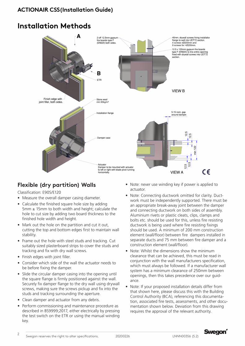
Flexible (dry partition) Walls Classification: E90S/E120 • Measure the overall damper casing diameter.
• Calculate the finished square hole size by adding 5mm ± 15mm to both width and height; calculate the hole to cut size by adding two board thickness to the finished hole width and height.
• Mark out the hole on the partition and cut it out, cutting the top and bottom edges first to maintain wall stability.
• Frame out the hole with steel studs and tracking. Cut suitably sized plasterboard strips to cover the studs and tracking and fix with dry wall screws.
• Finish edges with joint filler.
• Consider which side of the wall the actuator needs to be before fixing the damper.
• Slide the circular damper casing into the opening until the square flange is firmly positioned against the wall. Securely fix damper flange to the dry wall using drywall screws, making sure the screws pickup and fix into the studs and tracking surrounding the aperture.
• Clean damper and actuator from any debris.
• Perform commissioning and maintenance procedure as described in BS9999;2017, either electrically by pressing the test switch on the ETR or using the manual winding key.
Installation Methods
• Note: never use winding key if power is applied to actuator.
• Note: Connecting ductwork omitted for clarity. Duct-work must be independently supported. There must be an appropriate break-away joint between the damper and connecting ductwork on both sides of assembly. Aluminium rivets or plastic cleats, clips, clamps and bolts etc. should be used for this, unless fire resisting ductwork is being used where fire resisting fixings should be used. A minimum of 200 mm construction element (wall/floor) between fire dampers installed in separate ducts and 75 mm between fire damper and a construction element (wall/floor).
• Note: Whilst the dimensions show the minimum clearance that can be achieved, this must be read in conjunction with the wall manufacturers specification, which must always be followed. If a manufacturer wall system has a minimum clearance of 250mm between openings, then this takes precedence over our guid-ance.
• Note: If your proposed installation details differ from that shown here, please discuss this with the Building Control Authority (BCA), referencing this documenta-tion, associated fire tests, assessments, and other docu-mentation shown below. Deviation from this drawing requires the approval of the relevant authority.

3LNNN00356 (5.2) 20200226 Swegon reserves the right to alter specifications.
ACTIONAIR CSS(Installation Guide)
Comments:Rev:Drawn By: M. Bushell
Approved By:
A. Hill
1 of 1 Reference No:
S.GoreDate:
Date:
By: Date:
28/11/201922/05/2019
29/11/2019
Date:
C
Checked By:
Sheet Rev
AAF12822
Description:
If your proposed installation details differ fromthat shown here, please discuss this with the Building Control Authority (BCA), referencing this documentation, associated fire tests, assessments, and other documentation shownbelow. Deviation from this drawing requires the approval of the relevant authority.
Installation Detail
Connecting ductwork omitted for clarity. Ductwork must be independently supported. There must be an appropriate break-away joint between the damper and connecting ductwork on both sides of assembly. Aluminium rivets orplastic cleats, clips, clamps and bolts etc. should be used for this, unless fire resisting ductwork is being used where fire resisting fixings should be used. A minimum of 200 mm construction element (wall/floor) between fire dampers installed in separate ducts and 75 mmbetween fire damper and a construction element (wall/floor).
VIEW A
© Swegon Air Management LimitedSouth Street, Whitstable, Kent CT5 3DU
Tel: +44 (0)1227 276100Fax: +44 (0)1227 264262
www.swegonair.co.uk
Applicable Test Report to BS EN1366-2:
BRE P112628-1012
MINUTESE60SFire Resistance
Integrity and Leakage
A ECN1927 MJB 14-08-19
Damper Size Range (mm)
VERTICAL APPLICATIONCSS CIRCULAR SMOKE SHIELD
SIDE FIX - SINGLE PLATE
Ø100mm. - Ø355mm.
MINUTESE90Fire Resistance Integrity
Suitable fire resisting steel fixing 4mm x 60mm. min. fixing installation flange to wall. 4 screws ≤Ø200mm and 8 screws for >Ø200mm.
If size and condition permits, a circular hole 10-30mm larger thanthe damper casing diameter can be drilled / cut.
B ECN1955 MJB 06-11-19C ECN1961 MJB 29-11-19
Rigid (Masonry) Walls construction Classification: E90S/E120 • Measure the overall damper casing diameter. Calculate
the finished square hole size by adding 10mm ± 5mm to both width and height.
• Mark out the hole on the wall and cut it out, cutting the top and bottom edges first to maintain wall stabil-ity.
• If size and condition permits, a circular hole 10-30mm larger than the damper casing diameter can be drilled / cut.
• Consider which side of the wall the actuator needs to be before fixing the damper.
• Slide the circular damper casing into the opening until the square flange is firmly positioned against the wall. Drill out the pre-punched flange fixing holes to accom-modate suitable fire resisting steel fixings, (minimum M4x60mm) securely fix damper flange to wall.
• Clean damper and actuator from any debris.
• Perform commissioning and maintenance procedure, as described in BS9999;2017, either electrically by pressing the test switch on the ETR or using the manual winding key.
• Note: never use winding key if power is applied to actuator.
• Note: Connecting ductwork omitted for clarity. Duct-work must be independently supported. There must be an appropriate break-away joint between the damper and connecting ductwork on both sides of assembly. Aluminium rivets or plastic cleats, clips, clamps and bolts etc. should be used for this, unless fire resisting ductwork is being used where fire resisting fixings should be used. A minimum of 200 mm construction element (wall/floor) between fire dampers installed in separate ducts and 75 mm between fire damper and a construction element (wall/floor).
• Note: If your proposed installation details differ from that shown here, please discuss this with the Building Control Authority (BCA), referencing this documenta-tion, associated fire tests, assessments, and other docu-mentation shown below. Deviation from this drawing requires the approval of the relevant authority.
• Note: The actuator must be located on the right or left hand side of the damper fitted in any orientation.

ACTIONAIR CSS(Installation Guide)
4Swegon reserves the right to alter specifications. 20200226 LNNN00356 (5.2)
Comments:Rev:Drawn By: M. Bushell
Approved By:
A. Hill
1 of 1 Reference No:
S. GoreDate:
Date:
By: Date:
28/11/201922/05/2019
29/11/2019
Date:
C
Checked By:
Sheet Rev
AAF12821
Description:
If your proposed installation details differ from that shown here, please discuss this with the Building Control Authority (BCA), referencing this documentation, associated fire tests, assessments, and other documentation shown below. Deviation from this drawing requires theapproval of the relevant authority.
Installation Detail
Connecting ductwork omitted for clarity. Ductwork must be independently supported. There must be an appropriate break-away jointbetween the damper and connecting ductwork on both sides of assembly. Aluminium rivets orplastic cleats, clips, clamps and bolts etc. should be used for this, unless fire resisting ductwork is being used where fire resisting fixings should be used. A minimum of 200 mmconstruction element (wall/floor) between fire dampers installed in separate ducts and 75 mm between fire damper and a construction element (wall/floor).
Concrete floor(min. 580Kg/m³)
© Swegon Air Management LimitedSouth Street, Whitstable, Kent CT5 3DU
Tel: +44 (0)1227 276100Fax: +44 (0)1227 264262
www.swegonair.co.uk
Applicable Test Report to BS EN1366-2:
BRE P112628-1013
MINUTESE90SFire Resistance Integrity
and Leakage
A ECN1927 MJB 14-08-19
Damper Size Range (mm)
HORIZONTAL APPLICATIONCSS - CIRCULAR SMOKE SHIELD
SIDE FIX - SINGLE PLATE
Ø100mm. - Ø355mm.
Suitable fire resisting steel fixing 4mm x 60mm. min. fixing installation flange to slab. 4 screws ≤Ø200mm
and 8 screws for >Ø200mm.
Installation flange
MINUTESE120Fire Resistance Integrity
If size and condition permits, a circular hole 10-30mm larger thanthe damper casing diameter can be drilled / cut.
B ECN1955 MJB 06-11-19C ECN1961 MJB 29-11-19
Rigid (Masonry) Floor construction Classification: E120S• Measure the overall damper casing diameter. Calculate
the finished square hole size by adding 10mm ± 5mm to both width and height.
• Mark out the hole on the wall and cut it out, cutting the top and bottom edges first to maintain wall stabil-ity.
• If size and condition permits, a circular hole 10-30mm larger than the damper casing diameter can be drilled / cut.
• Consider which side of the wall the actuator needs to be before fixing the damper.
• Slide the circular damper casing into the opening until the square flange is firmly positioned against the wall. Drill out the pre-punched flange fixing holes to accom-modate suitable fire resisting steel fixings, (minimum M4x60mm) securely fix damper flange to wall.
• Clean damper and actuator from any debris.
• Perform commissioning and maintenance procedure, as described in BS9999;2017, either electrically by pressing the test switch on the ETR or using the manual winding key.
• Note: never use winding key if power is applied to actuator.
• Note: Connecting ductwork omitted for clarity. Duct-work must be independently supported. There must be an appropriate break-away joint between the damper and connecting ductwork on both sides of assembly. Aluminium rivets or plastic cleats, clips, clamps and bolts etc. should be used for this, unless fire resisting ductwork is being used where fire resisting fixings should be used. A minimum of 200 mm construction element (wall/floor) between fire dampers installed in separate ducts and 75 mm between fire damper and a construction element (wall/floor).
• Note the 200mm minimum dimension we state must be confirmed as suitable by the structural engineer, as the wall or floor may require to be larger to maintain the required support or strength.
• Note: If your proposed installation details differ from that shown here, please discuss this with the Building Control Authority (BCA), referencing this documenta-tion, associated fire tests, assessments, and other docu-mentation shown below. Deviation from this drawing requires the approval of the relevant authority.
• Note: The actuator must be located on the right or left hand side of the damper fitted in any orientation.

5LNNN00356 (5.2) 20200226 Swegon reserves the right to alter specifications.
ACTIONAIR CSS(Installation Guide)
Commissioning and periodic maintenanceMaintenance Requirements• Requirements as per BS9999:2017
• Arrangements should be made for all fire dampers to be tested by a competent person on completion of the installation and at least annually, and to be repaired or replaced immediately if found to be faulty.
• Spring-operated fire dampers should be tested annu-ally, and fire dampers situated in dust-laden and similar atmospheres should be tested much more frequently, at periods suited to the degree of pollution.
• Arrangements should be made for periodic mainte-nance of any smoke detector system used to operate fire dampers and for such system(s) to be tested by a competent person after installation to determine whether detection occurs at the appropriate design smoke density. Any smoke detector system that is found to be faulty should be either repaired or replaced immediately
Maintenance GuidelinesAs detailed in the procedures outlined below.
• The units should be carefully inspected and cleaned
• The units should then be lubricated with a light oil, by wiping this over all the surfaces.
• Actuators should be operated to ensure that it moves the blades from open to closed and the reverse.
• If the end switches (in the actuator) are being used, it should be checked that they are actually indicating that the blades are open or closed. This is done by running a cycle and checking both the blades (open and closed) and the indication that the micro switches are feeding back
Cleaning procedure• The units should be carefully inspected and cleaned
using light lubricant.
• The units should then be lubricated with a light oil, by wiping this over all the surfaces.
• Actuators should be operated to ensure that it moves the blades from open to closed and the reverse.
• If the end switches (in the actuator) are being used, it should be checked that they are indicating that the blades are open or closed. This is done by running a cycle and checking both the blades (open and closed) and the indication that the micro switches are feeding back to.
• If damper is stiff to operate lubricate blade ends, open and close damper successively until the damper moves with ease. (This may necessitate removal of the actua-tor and operating the blades manually by the drive shaft).
• Refit actuator and re-test.
• Clean off excessive lubricant.
Mechanical operation procedure• As an interim check, the damper should be manually reset
and released using the manual reset key provided, (refer to Control Actuator label) to ensure that correct mechanical operation is achieved. This feature may be used for system commissioning when electrical power is unavailable. Note however, the ETR is not operable without electrical power, and the damper will not close automatically should a temperature rise or fire occur. A manual test switch allows periodic operation of the damper for testing purposes, simulating actual fail-safe release under fire conditions.
• The associated electrical Control Actuators are available in 24V or 230V versions. Also available with 95° Probe as an option. Probe section only available as a spare replacement part.
ElectricalOverview• Fail-safe is by means of a unique and patented Electri-
cal Thermal Release (ETR) which operates at 72°C or if power supply is interrupted. The ETR incorporates a safety feature, that ensures the fail-safe status of the damper if the ETR is not fitted on to the ductwork.
• Additionally, a green LED lamp is built into the ETR hous-ing. This gives the user a simple and clear visual check that the Actuator is receiving power, the ETR is correctly fitted, and the thermal fuse is intact.
• One metre of halogen free low smoke and fume electric cable is fitted to each control actuator for convenience of on-site wiring. This provides the distinct safety advantage of all electrics terminating outside the duct, eliminating potential in-duct fire hazards from wiring faults. The Electrical Thermal Release is pre-wired with 0.5m halogen free low smoke and fume cabling to the 'COMPACT-M5' and 'COMPACT-M6' actuators.
• A Manual test button on the ETR allows periodic operation of damper, simulating actual fail safe release under smoke/fire conditions.
Control actuator wiring procedure• If integrating this unit with an ACTIONPAC damper control
system please refer to the relevant catalogue and specific project details.
Electrical connection and final operation test procedure• The unit must be wired as described in the Application
and Wiring section.
• When power is available, the unit must be checked for electrical operation.
• Power on to motor open, power off to spring close.
• The unit must also be checked by moving and holding the test switch on the ETR to confirm that the damper closes.
• When pressure is removed from the switch the damper will re-open. This may be done after the initial installa-tion test, to provide periodic operation of the damper to simulate actual fail-safe closure under fire conditions.

ACTIONAIR CSS(Installation Guide)
6Swegon reserves the right to alter specifications. 20200226 LNNN00356 (5.2)
Replacement of actuator and ETRRemoving ETR • Undo the 2 self-tapping screws with a No. 1 Pozi drive
screwdriver and remove the ETR from the hole. Con-tinuing to undo the 2 screws allows separation of the two pieces of the ETR. Replace old ETR with new (see below).
Removing actuator fasteners
• With power removed and the damper in the closed position wind the actuator anticlockwise 2-3 turns using the 5mm Allen key provided and activate the locking mechanism.
• Unscrew and remove the two bolts holding the actua-tor to the bracket using a 5mm. Allen key. Unscrew and remove the bolt and washer holding the actuator to the shaft using an 8mm A/F spanner.
Checking damper blade starting position • Damper blade in closed position for the ‘Fail-Safe-
Closed’ This is also a good opportunity to check the condition of the white seal around the circumference of the blade for any damage.
Pretensioning
Pretensioning the damper to ensure full closure. The damper blade is designed to be pretensioned with the actuator fitted.
Actuator Orientation
• The actuator can be fitted in one of three different positions depending on your preference. Now is the time to decide.
• If different from position supplied 2 M6 nuts (by others) will be required prior to changing.
Actuator Fitting• Manually wind actuator clockwise to align the 2 fixing
screw holes (see image right)and ½ turn anti-clockwise quickly to lock it for fail safe closed position.
• Screw fix actuator to bracket. Fit screw supplied with actuator through mudguard washer and into the drive shaft.
• Tighten screw into the shaft on the actuator end, 5Nm. Max, torque.
• Fully reset and release actuator by manually winding to fully open and then releasing, noting blade contacts both ‘blade stop’ positions using manual reset key (5mm cranked Allen key) supplied with actuator.
Fit new ETR or replace ETR thermal probe
• For damper sizes greater than Ø100mm. fit the ETR into the pre-punched hole in the circular case using a No.1 Pozi drive screwdriver to tighten the two self-tapping screws supplied with the ETR.
• For damper size Ø100mm. Fit to pre-punched hole in the side of actuator bracket and through a grommet in case beneath. Tighten using a No.1 Pozi drive screw-driver to tighten the two self-tapping screws supplied with the ETR. NOTE fully tighten the ETR so that its two-part case is completely together to ensure electri-cal continuity inside.
Electrical Connection and Final Operational Test• When power is available, the unit must be checked for
electrical operation. Power on to motor open, power off to spring close (fail-safe-closed). The unit must also be checked by pushing and holding the test switch on the ETR to confirm that the damper closes. When pressure is removed from the switch the damper will re-open. This may be done after the initial installation test, to provide periodic operation of the damper to simulate actual fail-safe closure under fire conditions.
• Note: Application of supply voltage will automatically override the manual locking mechanism.

7LNNN00356 (5.2) 20200226 Swegon reserves the right to alter specifications.
ACTIONAIR CSS(Installation Guide)
Wiring Diagrams

ACTIONAIR CSS(Installation Guide)
8Swegon reserves the right to alter specifications. 20200226 LNNN00356 (5.2)
Inspection and handover check sheetThis certificate applies only to Swegon Fire Dampers. The installer must complete this installation certificate when installing fire and smoke dampers. A separate certificate must be completed for each individual fire and smoke damper.
Question Action
1 Are the dampers the correct type? Confirm damper is correct type i.e. CSS
2 Are the dampers located correctly? The damper location is to be checked against the installa-tion drawings/details
3 Are the dampers correctly identified? Unique system ID to be clearly indicated on the damper or other agreed location.
4 Have supports for both the damper and the adja-cent ductwork been installed in accordance with the approved manner?
5 Are the dampers fitted in the correct orientation? Confirm the damper is installed with the actuator on the left or right hand side. Not on the top or the bottom (i.e. blade pivot running vertically).
6 Is access through the ductwork, to the damper unobstructed?
Unobstructed space should be provided for safe access to the damper. This must include access through ceiling voids and adjacent services. Damper installer to advise the system designer if problems are foreseen.
7 Has the space around the damper and within the opening been left clear and not been used for other services?
Other services within the installation opening will invali-date the installation method. Damper installer to advise the lead contractor if problems are foreseen.
8 Using the access opening provided, are the damper blades in the open position?
Check position of damper blades.
9 Has the damper been checked for internal cleanli-ness, free from damage and that vertical casings in particu-lar are free from debris?
With the damper in the closed position, inspect for damage.
10 Has the damper been released to simulate opera-tion of the thermal release? (Damper drop test)
Ensure damper operation is free from interference.
11 Have the damper blades been re-set following drop test and the access panel replaced?
After re-setting the damper, check the position shown on the blade position indicator is correct.
12 At the time of damper handover, is the fire barrier and penetration seal complete?
Damper installer to record on the handover register if any following trades are still to complete their activities.
13 Is the damper installation complete and available for handover prior to system commissioning?
Obtain the relevant acceptance of the damper installation from the CDM coordinator.
14 Is the completed handover register cross-refer-enced back to the identification codes listed in the system designers damper schedule?
Damper Unique System I.D: ............................................................................................................................................................................... Name of installation location:............................................................................................................................................................................. Address:.................................................................................................................................................................................................................... Installation location identification section/floor/room: .............................................................................................................................. Damper product type: ......................................................................................................................................................................................... Release fuse temperature: .................................................................................................................................................................................. Notes/Considerations: ...........................................................................................................................................................................................Installed by: ............................................................................................................................................................................................................. Company Name: .................................................................................................................................................................................................... Address: .................................................................................................................................................................................................................... Company Telephone No: ..................................................................................................................................................................................... Installers Name: ...................................................................................................................................................................................................... Installers Telephone No: ....................................................................................................................................................................................... Date of installation: ...............................................................................................................................................................................................
It is hereby verified that the damper detailed above has been installed and tested according to the manufactures recommendations:
Installers signature: ................................................................................................ Date: ................................................