Contents Han K 3/0, K 3/2 / Han HC Modular Page · Seal NBR Limiting temperatures - 40 OC / +125 OC...
30
14 . 01 Han HC Modular Contents Han ® K 3/0, K 3/2 / Han ® HC Modular Page Technical characteristics Han ® K 3/0, Han ® K 3/2 . . . . . . . . . . . . . . . . . . . . 14.10 Inserts Han ® K 3/0, Han ® K 3/2 . . . . . . . . . . . . . . . . . . . . . . . . . . . . . . . . . . 14.11 Han ® 24 HPR special hoods/housings for Han ® K 3/0, Han ® K 3/2 . . . . . . . 14.12 Technical characteristics Han ® HC Modular 350 . . . . . . . . . . . . . . . . . . . . . 14.14 Contacts Han ® HC Modular 350 . . . . . . . . . . . . . . . . . . . . . . . . . . . . . . . . . 14.15 Hoods/housings for working voltage: 2 000 V Han ® HC Modular . . . . . . . . . 14.16 Hoods/housings for working voltage: 4 000 V Han ® HC Modular . . . . . . . . . 14.17 Assembly details for Han ® HC Modular 350 . . . . . . . . . . . . . . . . . . . . . . . . . 14.19 Technical characteristics Han ® HC Modular 650 . . . . . . . . . . . . . . . . . . . . . 14.20 Contacts Han ® HC Modular 650 . . . . . . . . . . . . . . . . . . . . . . . . . . . . . . . . . 14.21 Hoods/housings for Han ® HC Modular 650 . . . . . . . . . . . . . . . . . . . . . . . . . 14.21 Assembly details for Han ® HC Modular 650 . . . . . . . . . . . . . . . . . . . . . . . . . 14.22 Han ® 48 HPR . . . . . . . . . . . . . . . . . . . . . . . . . . . . . . . . . . . . . . . . . . . . . . . . 14.23
-
Upload
truongtuong -
Category
Documents
-
view
215 -
download
0
Transcript of Contents Han K 3/0, K 3/2 / Han HC Modular Page · Seal NBR Limiting temperatures - 40 OC / +125 OC...
14.01
Han HC Modular
Contents
Han® K 3/0, K 3/2 / Han® HC Modular Page
Technical characteristics Han® K 3/0, Han® K 3/2 . . . . . . . . . . . . . . . . . . . . 14.10
Inserts Han® K 3/0, Han® K 3/2 . . . . . . . . . . . . . . . . . . . . . . . . . . . . . . . . . . 14.11
Han® 24 HPR special hoods/housings for Han® K 3/0, Han® K 3/2 . . . . . . . 14.12
Technical characteristics Han® HC Modular 350 . . . . . . . . . . . . . . . . . . . . . 14.14
Contacts Han® HC Modular 350 . . . . . . . . . . . . . . . . . . . . . . . . . . . . . . . . . 14.15
Hoods/housings for working voltage: 2 000 V Han® HC Modular . . . . . . . . . 14.16
Hoods/housings for working voltage: 4 000 V Han® HC Modular . . . . . . . . . 14.17
Assembly details for Han® HC Modular 350 . . . . . . . . . . . . . . . . . . . . . . . . . 14.19
Technical characteristics Han® HC Modular 650 . . . . . . . . . . . . . . . . . . . . . 14.20
Contacts Han® HC Modular 650 . . . . . . . . . . . . . . . . . . . . . . . . . . . . . . . . . 14.21
Hoods/housings for Han® HC Modular 650 . . . . . . . . . . . . . . . . . . . . . . . . . 14.21
Assembly details for Han® HC Modular 650 . . . . . . . . . . . . . . . . . . . . . . . . . 14.22
Han® 48 HPR . . . . . . . . . . . . . . . . . . . . . . . . . . . . . . . . . . . . . . . . . . . . . . . . 14.23

14.10
Han HCModular
Han® K 3/0, Han® K 3/2 Technical characteristics
Current carrying capacity acc. to IEC 512
The current carrying capacity is limited by maximum temperatureof materials for inserts and contacts including terminals. Thecurrent capacity-curve is valid for continuous, not interruptedcurrent-loaded contacts of connectors when simultaneous poweron all contacts is given, without exceeding the maximum temperature.
Control and test procedures according to DIN IEC 512-3.
Technical characteristicsMaterial corrosion resistant
aluminium alloySurface
- top coat Epoxy powder paintLocking elements V2AKind of locking ScrewSeal NBRLimiting temperatures - 40 OC / +125 OCDegree of protection acc. to DINEN 60 529 for coupled connector IP 68
Features ● Epoxy powder paint finish● EMC protection● Corrosion resistant● Pressure tight
● Only to be used with Han® 24 HPR special hoods and housings (see page 14.12)
● Only available with axial screw termination
● The vertical and angled versions offer solutions for almost allapplications
● The ideal connector for transmission of high currents requiringlittle space
Wor
king
cur
rent
Ambient temperature
➀ Wire gauge: 35 mm2
➁ Wire gauge: 50 mm2
➂ Wire gauge: 70 mm2
Han® HPR hoods/housings
Features
1) geometrical diameter
Specifications DIN VDE 0627DIN VDE 0110DIN EN 61 984
InsertsNumber of contacts 3, 3/2 + PE
Electrical dataacc. to DIN EN 61 984
Power area 200 A 1150/2000 V 8 kV 3
Working currentWorking voltage conductor – groundWorking voltage conductor – conductorRated impulse voltagePollution degree
– Pollution degree 2 also 200 A 2000 V 12 kV 2
Signal area 16 A 400 V 6 kV 3
Working currentWorking voltageRated impulse voltagePollution degree
– Pollution degree 2 also 16 A 500 V 6 kV 2
Insulation resistance ≥ 1010 ΩMaterial PolycarbonateLimiting temperatures - 40 OC / +125 OCFlammability acc. to UL 94 V 0Mechanical working life
– Mating cycles ≥ 500
ContactsMaterial copper alloySurface silverContact resistance ≤ 0.2 mΩ
Axial screw contact- Wire gauge mm² 35 50 70- Tightening torque Nm 8 9 10
Power contact- Wire gauge1) 35 - 70 mm²- AWG 2 - 2/0- Tightening torque 8 - 10 Nm- Hexagonal wrench SW 5, 09 99 000 0371,
page 99.05- Stripping length 22 mm
PE contact (only Han K 3/2)1)
- Wire gauge 16 - 35 mm²- AWG 5 - 2- Tightening torque 6 Nm- Hexagonal wrench SW 4, 09 99 000 0370,
page 99.05- Stripping length 14 mm
Signal contact (only Han K 3/2)- Wire gauge 2,5 mm²- AWG 14- Tightening torque 0.5 Nm- Stripping length 7 mm
14.11
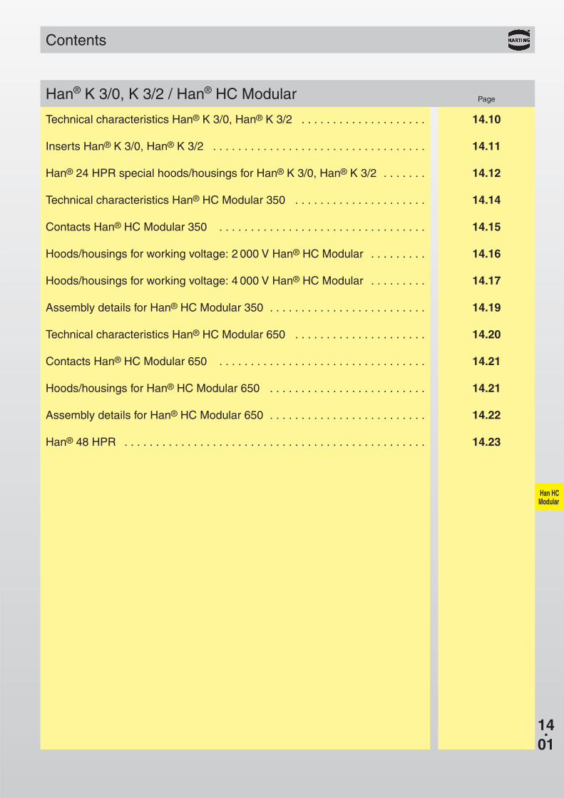
3/0 09 38 005 2621 09 38 005 2721
3/0 09 38 005 2622 09 38 005 2722
Han® K
Han® K 3/0, Han® K 3/2
3/2 09 38 005 2601 09 38 005 2701
3/2 09 38 005 2602 09 38 005 2702
Han® K
1150/2000 V 200 A
X
X
X
X
X
X
X
X
Han HCModular
Axial screw terminaltop-entry
angled
Part No.
Identification Serie Male insert (M) Female insert (F) Drawing Dimensions in mm
Inserts
Number of contacts
3/0 without3/2 with
1) Distance for contact max. 21 mm
Axial screw terminaltop-entry
angled
1) Distance for contact max. 21 mm
Stock items in bold type

14.12
19 40 024 0461 3 x 25
Han® K3/0
19 40 024 0420 63
Han® K3/2
19 40 024 1231 3 x 25
Han® K3/0
09 40 024 0311 24
Han® K3/0 + 3/2
19 40 024 0931 3 x 25
19 40 024 0914 50
19 40 024 0631 3 x 25
Han® 24 HPR Special hoods/housings for Han® K 3/0 – 3/2
Part No. SerieIdentification Screw locking M Drawing Dimensions in mm
Han HCModular
Hoodtop-entry
top-entryfor M 63
angled entry
Housing surface mountingstraight version
Housing bulkhead mounting
horizontal version
View X
View X
View X
Panel cut out:108 x 35 mm
Stock items in bold type
14.13
Han HCModular
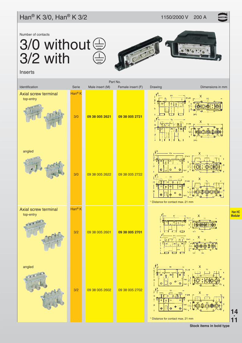
Application
Motor connection of the traction bogiewith Han® K 3/0 and Han® HPRhood/housingBombardier Transportation,Siemens AG, ALSTOM
Regional Express Railcarsof the series ET 424-426Bombardier Transportation,Siemens AG, ALSTOM
14.14
Han HCModular
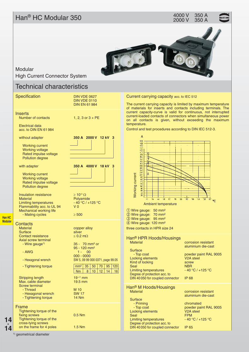
Han® HC Modular 350 4000 V 350 A2000 V 350 A
Technical characteristicsCurrent carrying capacity acc. to IEC 512
The current carrying capacity is limited by maximum temperatureof materials for inserts and contacts including terminals. Thecurrent capacity-curve is valid for continuous, not interruptedcurrent-loaded contacts of connectors when simultaneous poweron all contacts is given, without exceeding the maximum temperature.
Control and test procedures according to DIN IEC 512-3.
Wor
king
cur
rent
Ambient temperature
➀ Wire gauge: 50 mm²➁ Wire gauge: 70 mm²➂ Wire gauge: 95 mm²➃ Wire gauge: 120 mm²
three contacts in HPR size 24
1) geometrical diameter
ModularHigh Current Connector System
Specification DIN VDE 0627DIN VDE 0110DIN EN 61 984
InsertsNumber of contacts 1, 2, 3 or 3 + PE
Electrical data acc. to DIN EN 61 984
without adapter 350 A 2000 V 12 kV 3
Working currentWorking voltageRated impulse voltagePollution degree
with adapter 350 A 4000 V 18 kV 3
Working currentWorking voltageRated impulse voltagePollution degree
Insulation resistance ≥ 1010 ΩMaterial PolyamideLimiting temperatures - 40 OC / +125 OCFlammability acc. to UL 94 V 0Mechanical working life
- Mating cycles ≥ 500
ContactsMaterial copper alloySurface silverContact resistance ≤ 0.2 mΩAxial screw terminal
- Wire gauge1) 35 - 70 mm² or95 - 120 mm²
- AWG 1 - 00000 - 0000
- Hexagonal wrench SW 5, 09 99 000 0371, page 99.05
- Tightening torque mm² 35 50 70 95 120
Nm 8 10 12 14 16
Stripping length 19 +1 mmMax. cable diameter 19.5 mmScrew terminal
- Thread M 10- Hexagonal wrench SW 17- Tightening torque 14 Nm
Han® HPR Hoods/HousingsMaterial corrosion resistant
aluminium die-castSurface
- Top coat powder paint RAL 9005Locking elements V2A steelKind of locking screwSeal NBRLimiting temperatures - 40 OC / +125 OCDegree of protection acc. to DIN 40 050 for coupled connector IP 68
FrameTightening torque of the fixing screws 0.5 NmTightening torque of the cross-tying screwson the frame for 4 poles 1.5 Nm
Han® M Hoods/HousingsMaterial corrosion resistant
aluminium die-castSurface
- Priming chromated- Top coat powder paint RAL 9005
Locking elements V2A steelSeal FPMLimiting temperatures - 40 OC / +125 OCDegree of protection acc. to DIN 40 050 for coupled connector IP 65

14.15
09 11 001 2651 09 11 001 2751 35 - 70 mm²09 11 001 2652 09 11 001 2752 95 - 120 mm²
09 99 000 0371
09 11 000 6156 09 11 000 6256 35 - 70 mm²
M 10
M 10
Han HC Modular
Han® HC Modular 350
19 36 000 5134 25 3019 36 000 5135 32 40
Part No. WireContacts Male contact (M) Female contact (F) gauge Drawing Dimensions in mm
Straight versionwith screw terminal only for housing bulkhead mounting
09 11 001 2655 09 11 001 2755 for cable lugup to max.120 mm²
Stock items in bold type
Metal versionwith O-Ring
Hexagonaladapter Part No. M SW Drawing Dimensions in mm
with axial screw terminal
Hexagonal wrenchadapter(SW 5)
PE contactwith axial screw terminal

25 19 40 006 041132 19 40 006 0412
– 09 40 006 0311
4 x 25 19 37 048 0401
– 09 37 048 0301
09 11 000 9951
09 11 000 9951
09 11 000 9954
09 11 000 9955
14.16
6 B 70 133 48
Han HC Modular
Frame Part No.Hoods/Housingstop-entry M Part No.
HoodHan® HPR 6 B
Housing bulkhead mountingHan® HPR 6 B
HoodHan® 48 M
Housing bulkhead mountingHan® 48 M
1 pole for hood
1 pole for housing
3 poles with PEfor hood
3 poles with PEfor housing
Han® HC Modular for working voltage: 2 000 V
Size a b c
Hood
Housing
Stock items in bold type
14.17
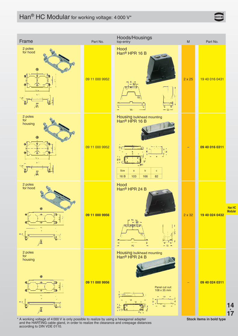
2 x 25 19 40 016 0431
– 09 40 016 0311
2 x 32 19 40 024 0432
– 09 40 024 0311
09 11 000 9952
09 11 000 9952
09 11 000 9956
09 11 000 9956
16 B 103 166 82
Han HC Modular
Han® HC Modular for working voltage: 4 000 V*
* A working voltage of 4 000 V is only possible to realize by using a hexagonal adapter and the HARTING cable gland, in order to realize the clearance and creepage distances according to DIN VDE 0110.
Frame Part No.Hoods/Housingstop-entry M Part No.
HoodHan® HPR 16 B
Housing bulkhead mountingHan® HPR 16 B
HoodHan® HPR 24 B
Housing bulkhead mountingHan® HPR 24 B
2 polesfor hood
2 poles for housing
2 polesfor hood
2 poles for housing
Panel cut out:108 x 35 mm
Size a b c
Stock items in bold type

3 x 25 19 40 024 0461
– 09 40 024 0311
3 x 25 19 40 024 0931
09 11 000 9963
14.18
3 x 25 19 40 024 1231
Han HC Modular
X
X
3 x 32 19 40 024 046709 11 000 9963
09 11 000 9963
09 11 000 9963
09 11 000 9963
24 B 130 193 108
* A working voltage of 4 000 V is only possible to realize by using a hexagonal adapter and the HARTING cable gland, in order to realize the clearance and creepage distances according to DIN VDE 0110.
Stock items in bold type
Han® HC Modular for working voltage: 4 000 V*
Frame Part No.Hoods/Housingstop-entry M Part No.
HoodHan® HPR 24 B
HoodHan® HPR 24 B
Housing bulkhead mounting
Han® HPR 24 B
Housingsurface mounting
Han® HPR 24 Bhorizontal version
3 poles
Housingsurface mounting
Han® HPR 24 Bstraight version
enclosed separately
3 poles
enclosed separately
3 poles
enclosed separately
3 poles
enclosed separately
3 poles
enclosed separately
Size a b c

14.19
1.
2.
3.
4.
A
B
C
Han HC Modular
Assembly Details
1. Strip cable to 19+1 mm.
2. Push conductors through the cable gland and the housing. Push the stripped end of the conductor intothe connection entry of the module until the insulation touches the contact.
3. To tighten the locking screw, a hexagonal wrench size 5 is needed. Insert the hexagonal wrench on themating side of the contact. At the same time, push the conductor over the axial screw. The locking screwhas to be tightened with the recommended tightening torque that is determined by the conductor’s crosssection (6 - 14 Nm).
4. Once all modules are terminated, they are mounted into the housing by means of two metal frames(tightening torque of the fixing screws = 0.5 Nm). The modules have a hexagonal around it which mateswith the metal frame.The heads of the fixing screws have to face the mating direction of the module. Dueto the hexagonal slot, each module can be used in 6 different positions (turning every 60 degreed) tocreate a coding system.
Therefore it is important that the corresponding modules are assembled in the correct position or matingis not possible.
5. After the assembly of the modules in thehousing, the tightening torque of the lockingscrew can be checked and corrected if neces-sary.
6. After final assembly of the contacts, the usershould ensure that the cable is adequatelystrain reliefed to protect the contact fromradial stress.
7. During the assembly of the frame for 4 polesthe following tightening torques have to betaken into consideration:A = 0.5 NmB = 1.5 NmC = 0.25 Nm
Han® HC Modular 350

14.20
Han HC Modular
Han® HC Modular 650 4000 V 650 A
Technical characteristics
Current carrying capacity acc. to IEC 512
The current carrying capacity is limited by maximum temperatureof materials for inserts and contacts including terminals. Thecurrent capacity-curve is valid for continuous, not interruptedcurrent-loaded contacts of connectors when simultaneous poweron all contacts is given, without exceeding the maximum temperature.
Control and test procedures according to DIN IEC 512-3.
Wor
king
cur
rent
[A]
Ambient temperature [°C]
➀ Wire gauge: 70 mm²➁ Wire gauge: 95 mm²➂ Wire gauge: 120 mm²
➃ Wire gauge: 150 mm²➄ Wire gauge: 180 mm²➅ Wire gauge: 240 mm²
with cable SHXAFO1x240, 4 kV
Modular High CurrentConnector System
Axial screw contact- Wire gauge mm² 70 95 120 150 185- Tightening torque Nm 12 14 16 17 18
min. length of wrench: 60 mm
InsertsNumber of contacts 1, 2
Electrical dataacc. to DIN EN 61 984 650 A 4000 V 18 kV 3
Working currentWorking voltageRated impulse voltagePollution degree
Insulation resistance ≥ 1010 ΩMaterial PolyamideLimiting temperatures - 40 OC / +125 OCFlammability acc. to UL 94 V 0Mechanical working life
- Mating cycles ≥ 500
ContactsMaterial copper alloySurface silverContact resistance ≤ 0.2 mΩAxial screw contact
- Wire gauge1) 70 - 120 mm² oder150 - 185 mm²
- MCM 138 - 236 oder300 - 350
Screw contact- Thread M 12- 16 - 18 Nm
Please ensure to hold up the contact with a wrench size 24 to apply the tightening torque
FrameMaterial V2ATightening torqueof the locking screws 0.5 Nm
Stripping length
Hexagonal wrenchAdapter (SW8) 09 99 000 0372
page 99.05
Han® HPR hoods/housingsMaterial Corrosion resistant
aluminium die-castSurface
- top coat Epoxy powder paint RAL 9005Locking elements V2AKind of locking screwSealing NBRLimiting temperatures - 40 OC / +125 OCDegree of protection acc. to DIN 40 050 for coupled connector IP 68
Specifications DIN VDE 0627DIN VDE 0110DIN EN 61 984
1) geometrical diameter
14.21
Han HC Modular
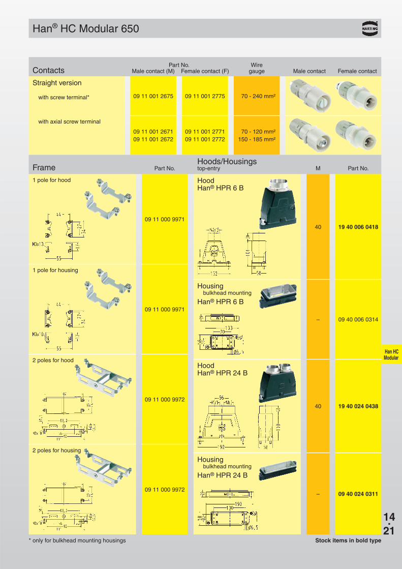
09 11 001 2675 09 11 001 2775 70 - 240 mm²
09 11 001 2671 09 11 001 2771 70 - 120 mm²09 11 001 2672 09 11 001 2772 150 - 185 mm²
40 19 40 006 041809 11 000 9971
– 09 40 006 0314
09 11 000 9971
– 09 40 024 031109 11 000 9972
40 19 40 024 043809 11 000 9972
Han® HC Modular 650
Part No. WireContacts Male contact (M) Female contact (F) gauge Male contact Female contact
Straight version
with screw terminal*
with axial screw terminal
Stock items in bold type* only for bulkhead mounting housings
Frame Part No.Hoods/Housingstop-entry M Part No.
HoodHan® HPR 6 B
1 pole for hood
Housing bulkhead mounting
Han® HPR 6 B
1 pole for housing
Housing bulkhead mounting
Han® HPR 24 B
2 poles for housing
HoodHan® HPR 24 B
2 poles for hood

14.22
Han HC Modular
4. + 5.
2. + 3.
Han® HC Modular 650
Assembly details
1. Strip cable to 23+2 mm.
2. Push conductor through the cable glandand the housing. Push the stripped end ofthe conductor into the termination entry ofthe module until the insulation touches thecontact.
3. To tighten the axial screw, a hexagonalwrench size 8 is needed. Insert the hexag-onal wrench on the mating side of the con-tact. At the same time, push the conductorover the axial screw.The locking screw hasto be tightened with the recommendedtightening torque that is determined by theconductor’s cross section.
4. Once the modules are terminated, they aremounted into the housing by using twometal frames (tightening torque of the fix-ing screws = 0.5 Nm).The modules have 4pegs formed by 2 parallel ribs (each pegshapes like a “H”). Each rib takes 1 poleframe, where the lateral link has to go intothe relief of the frame.The 2 pole frames have 2 cutouts on thewall which get fitted to the “H”-shapedpegs (see figure).The heads of the screws have to face themating direction of the module. Coding canbe established by rotating the contact by90 degrees. Therefore it is important thatthe corresponding modules are assembledin the correct position otherwise mating isnot possible.
5. After assembling the modules in the hous-ing, the tightening torque of the lockingscrew can be checked and corrected ifnecessary.
6. After final assembly of the contacts, theuser should ensure that the cable is ad-equately strain reliefed to protect thecontact from radial stress.
1. Stripping length
Axialscrew
min. length of wrench: 60 mm
Hood
Housing bulkhead mounting
Termination entry
Frame
FixingScrews
Parallel ribs with H-shape
14.23
Han HC Modular
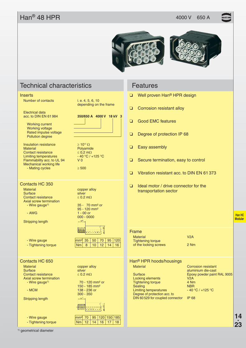
Han® 48 HPR 4000 V 650 A
Technical characteristics FeaturesInserts
Number of contacts i. e. 4, 5, 6, 10 depending on the frame
Electrical dataacc. to DIN EN 61 984 350/650 A 4000 V 18 kV 3
Working currentWorking voltageRated impulse voltagePollution degree
Insulation resistance ≥ 1010 ΩMaterial PolyamideContact resistance ≤ 0,2 mΩLimiting temperatures - 40 OC / +125 OCFlammability acc. to UL 94 V 0Mechanical working life
- Mating cycles ≥ 500
FrameMaterial V2ATightening torqueof the locking screws 2 Nm
Contacts HC 350Material copper alloySurface silverContact resistance ≤ 0.2 mΩAxial screw termination
- Wire gauge1) 35 - 70 mm² or95 - 120 mm²
- AWG 1 - 00 or000 - 0000
Stripping length
- Wire gauge mm² 35 50 70 95 120- Tightening torque Nm 8 10 12 14 16
Contacts HC 650Material copper alloySurface silverContact resistance ≤ 0.2 mΩAxial screw termination
- Wire gauge1) 70 - 120 mm² or150 - 185 mm²
- MCM 138 - 236 or300 - 350
Stripping length
- Wire gauge mm² 70 95 120 150 185- Tightening torque Nm 12 14 16 17 18
Han® HPR hoods/housingsMaterial Corrosion resistant
aluminium die-castSurface Epoxy powder paint RAL 9005Locking elements V2ATightening torque 4 NmSealing NBRLimiting temperatures - 40 OC / +125 OCDegree of protection acc. to DIN 60 529 for coupled connector IP 68
❏ Well proven Han® HPR design
❏ Corrosion resistant alloy
❏ Good EMC features
❏ Degree of protection IP 68
❏ Easy assembly
❏ Secure termination, easy to control
❏ Vibration resistant acc. to DIN EN 61 373
❏ Ideal motor / drive connector for thetransportation sector
1) geometrical diameter
14.24
Han HC Modular
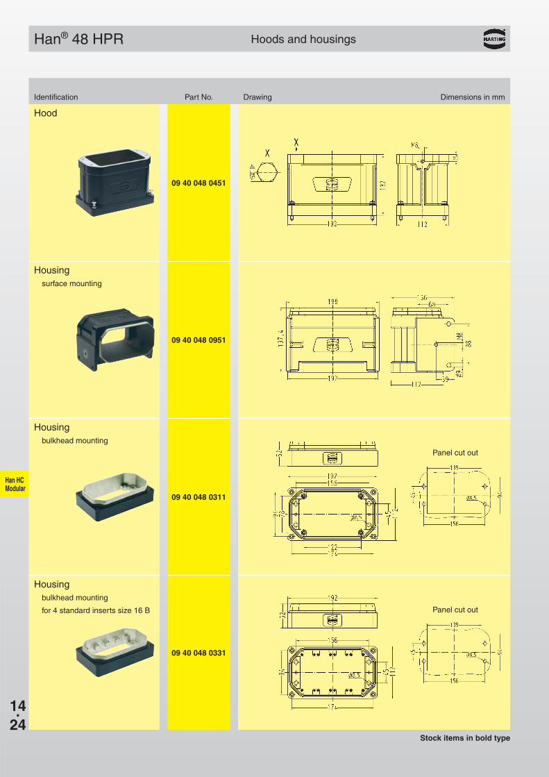
09 40 048 0451
Han® 48 HPR
09 40 048 0951
09 40 048 0311
09 40 048 0331
Hoods and housings
Identification Part No. Drawing Dimensions in mm
Hood
Housingsurface mounting
Housingbulkhead mounting
Housingbulkhead mounting
for 4 standard inserts size 16 B
Stock items in bold type
Panel cut out
Panel cut out
14.25
Han HC Modular
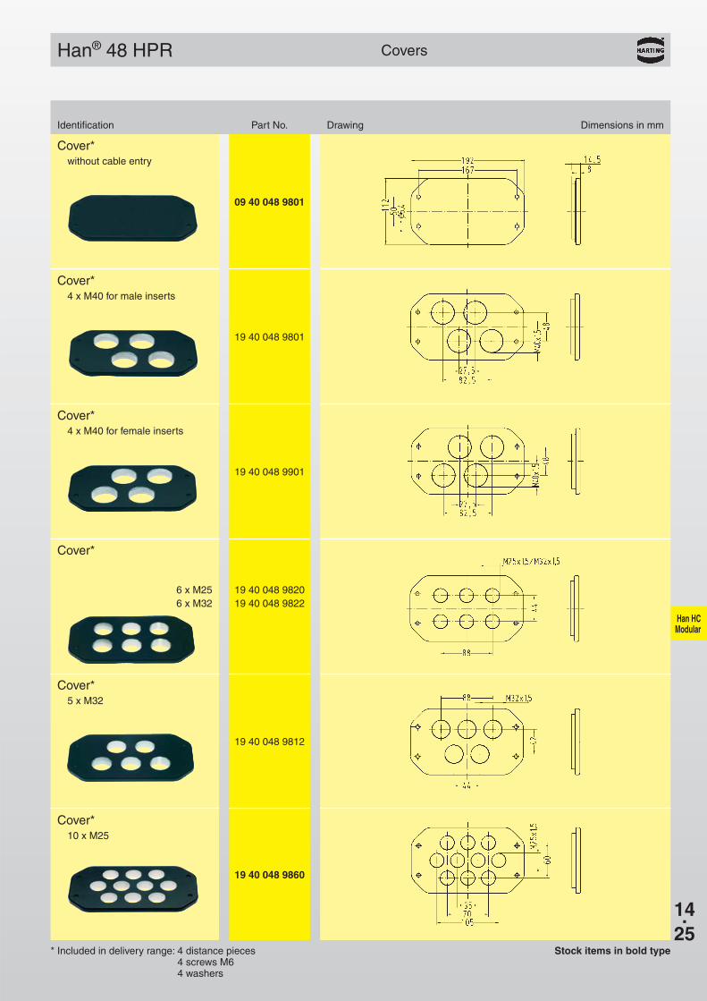
09 40 048 9801
Han® 48 HPR
19 40 048 9801
19 40 048 9901
19 40 048 982019 40 048 9822
6 x M256 x M32
19 40 048 9812
19 40 048 9860
Covers
Identification Part No. Drawing Dimensions in mm
Cover*without cable entry
Cover*4 x M40 for male inserts
Cover*4 x M40 for female inserts
Cover*
Cover*5 x M32
Cover*10 x M25
Stock items in bold type* Included in delivery range: 4 distance pieces4 screws M64 washers
14.26
Han HC Modular
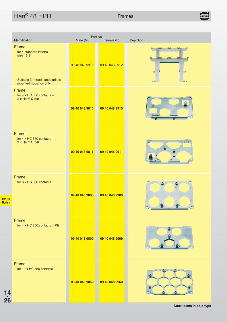
Han® 48 HPR
09 40 048 9912 09 40 048 9912
09 40 048 9810 09 40 048 9910
09 40 048 9811 09 40 048 9911
09 40 048 9806 09 40 048 9906
09 40 048 9809 09 40 048 9909
09 40 048 9860 09 40 048 9960
Frames
Part No.Identification Male (M) Female (F) Depiction
Framefor 4 standard insertssize 16 B
Stock items in bold type
Framefor 4 x HC 350 contacts +2 x Han® Q 5/0
Framefor 4 x HC 650 contacts +2 x Han® Q 5/0
Framefor 6 x HC 350 contacts
Framefor 4 x HC 350 contacts + PE
Framefor 10 x HC 350 contacts
Suitable for hoods and surfacemounted housings only
Han-Power
15.01
Power Distribution Page
Contents
Technical characteristics . . . . . . . . . . . . . . . . . . . . . . . . . . . . . . . . . . . . . . . . 15.10
Han-Power® S . . . . . . . . . . . . . . . . . . . . . . . . . . . . . . . . . . . . . . . . . . . . . . . . 15.12
Han® Q 8/0 . . . . . . . . . . . . . . . . . . . . . . . . . . . . . . . . . . . . . . . . . . . . . . . . . . 15.14
Han® Q 4/2 . . . . . . . . . . . . . . . . . . . . . . . . . . . . . . . . . . . . . . . . . . . . . . . . . . 15.16
System cables . . . . . . . . . . . . . . . . . . . . . . . . . . . . . . . . . . . . . . . . . . . . . . . 15.18
Accessories . . . . . . . . . . . . . . . . . . . . . . . . . . . . . . . . . . . . . . . . . . . . . . . . . 15.20

Han-Power
15.10
Han-Power®
Technical characteristics Current carrying capacitySpecifications DIN VDE 61 984
DIN VDE 0110
Inserts Han® Q 8/0Number of contacts 6 + PERated current (partly loaded) 25 ARated voltage 500 VRated impulse voltage 6 kVPollution degree 3Insulation resistance ≥ 1010 ΩFlammability acc. to UL 94 V 0Mechanical working life ≥ 500 mating cycles
Han® E contactsMaterial Copper alloySurface: hard silver plated 3 µm AgContact resistance ≤ 1 mΩCrimp terminal – mm² 2.5 - 4 mm²
– AWG 18 - 12
Inserts Han® Q 4/2Number of contacts 4/2 + PERated current 40 ARated voltage 400 / 690 VRated impulse voltage 6 kVPollution degree 3Insulation resistance ≥ 1010 ΩTemperature range -40 °C … +125 °CFlammability acc. to UL 94 V 0Mechanical working life ≥ 500 mating cycles
Han® C contactsMaterial Copper alloySurface: hard silver plated 5 µm AgContact resistance ≤ 0.3 mΩCrimp terminal – mm² 2.5 - 6 mm²
– AWG 14 - 10Max. insulation diameterof single strand 5 mm
Hoods/housingsMaterial PolycarbonateColour RAL 9005Sealing NBRTemperature range
– Connecting temperature –25 °C … +40 °C– Working temperature –25 °C … +80 °C
Flammability acc. to UL 94 V 0Protection degree acc. to DIN 40 050 in locked position IP 65
CableDesign of conductor acc. to DIN VDE 0295
and DIN VDE 0281Single strandWire gauge 2.5 mm²
Number of single strands 50 x 0.25 mm ØOuter diameter 3.6 mm Ø
Wire gauge 4 mm²Number of single strands 56 x 0.30 mm ØOuter diameter 4.2 mm Ø
Current carrying capacityThe current carrying capacity is limited by maximum temperatureof materials for inserts and contacts including terminals. Thecurrent capacity-curve is valid for continuous, not interruptedcurrent-loaded contacts of connectors when simultaneous poweron all contacts is given, without exceeding the maximum tempe-rature.
Control and test procedures according to DIN IEC 60 512-3.
Wor
king
cur
rent
[A]
Ambient temperature [oC]
Han® Q 8/0 partly loaded with wire gauge 7 x 4 mm²
➀ Han® Q 8/0 wire gauge: 2.5 mm²➁ Han® Q 8/0 wire gauge: 4.0 mm²
Wor
king
cur
rent
[A]
Ambient temperature [oC]
Han® Q 4/2 fully loaded with wire gauge 4 x 6 mm²
➀ Han® Q 4/2 wire gauge: 4 mm²➁ Han® Q 4/2 wire gauge: 6 mm²

Han-Power
15.11
09 12 000 996909 12 000 997009 12 000 997109 12 000 997209 12 000 9973
09 12 000 9974
Han-Power® S
Panel feed through sealings Part No. Drawing
Blind grommet
Cable-ø7 – 10
10 – 1313 – 1616 – 1919 – 22
Stock items in bold type
The Han-Power® S connector is suitable for theassembly of serial power bus. Having assembled theenergy supply Han-Power® S can be inserted at anyplace of the power cable. The cable mantle has to beremoved, the conductor is placed withoutinterruption in the IDC. Han-Power® S is suitable forcables with single strands manufactured acc. to DIN VDE 0281/ DIN VDE 0295 with wire gauges of2.5 mm² up to 6 mm². For the distribution of the deviceHan-Compact® hoods or cable to cable housings areused.
Features Description● 6 IDCs + PE for 2.5 mm² up to 6 mm² wire gauge
● No interruption of the energy supply
● Space-saving and compact design
● Leading protective ground within the insert
● Assembly with standard tools
● T-functionality for max. 500 V:– Energy bus
structure: 7 x 4 mm² or 7 x 6 mm²– Power supply
structure: 7 x 4,0 mm² (Han-Power® S)7 x 2.5 mm² (Han-Power® S)
● Marking of the terminal strip for the contact arrange-ment
● Power supply
– Han-Power® S: Power supply has to be realizedwith 1 x Han® Q 8/0 in a Han-Compact® cable tocable hood.
– Han-Power® S: Power supply has to be realizedwith 2 x Han® Q 8/0 in Han-Compact® hoods.
– Han-Power® S: Power supply has to be realizedwith 1 x Han® Q 4/2 in a Han-Compact® cable tocable hood.
Han-Power
15.12
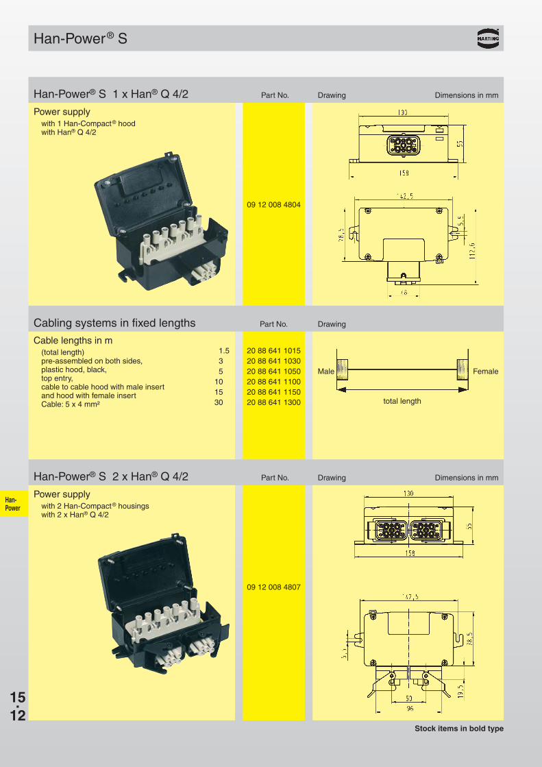
09 12 008 4804
20 88 641 101520 88 641 103020 88 641 105020 88 641 110020 88 641 115020 88 641 1300
Han-Power® S
09 12 008 4807
Han-Power® S 1 x Han® Q 4/2 Part No. Drawing Dimensions in mm
Power supplywith 1 Han-Compact® hoodwith Han® Q 4/2
Cabling systems in fixed lengths Part No. Drawing
Cable lengths in m(total length)pre-assembled on both sides,plastic hood, black,top entry,cable to cable hood with male insert and hood with female insertCable: 5 x 4 mm²
1.535
101530
Male
total length
Female
Stock items in bold type
Han-Power® S 2 x Han® Q 4/2 Part No. Drawing Dimensions in mm
Power supplywith 2 Han-Compact® housings with 2 x Han® Q 4/2

15.13
09 12 008 4801
20 88 841 001520 88 841 003020 88 841 005020 88 841 010020 88 841 015020 88 841 0300
09 12 008 4802
20 88 821 001520 88 821 003020 88 821 005020 88 821 010020 88 821 015020 88 821 0300
Han-Power® S
Han-Power
Han-Power® S 1 x Han® Q 8/0 Part No. Drawing Dimensions in mm
Power supplywith 1 Han-Compact® hoodwith Han® Q 8/0
Suitable Panel Feed Through sealingssee page PD10.02
Cabling systems in fixed lengths Part No. Drawing
Cable lengths in m(total length)pre-assembled on both sides,plastic hood, black,top entry,cable to cable hood with male insert and hood with female insertCable: 7 x 2.5 mm²
1.535
101530
Male
total length
Female
Han-Power® S 2 x Han® Q 8/0 Part No. Drawing Dimensions in mm
Power supplywith 2 screwed Han-Compact®
bulkhead mounted housings with 2 x Han® Q 8/0
Cabling systems in fixed lengths Part No. Drawing
Cable lengths in m(total length)pre-assembled on both sides,plastic hood, black,top entry,Cable: 7 x 2.5 mm²
1.535
101530
Male
total length
Female
Suitable Panel Feed Through sealingssee page PD10.02
Stock items in bold type

Han-Power
15.14
*
Han® Q 8/0 500 V 16 A
Features Technical characteristics❏ 8 contact chambers taking
the Han E® power contacts
❏ Space-saving and compact design
❏ Leading protective ground
❏ Crimp terminal with standardHan E® contacts
❏ Use of standard tools
❏ Insert is suitable for the hoods and housingsof the series Han® Q 8/0
❏ The contacts can be removed withthe aid of a removal tool from thetermination side
❏ conform product
❏ ISO 23570
Current carrying capacityThe current carrying capacity is limited by maximum temperatureof materials for inserts and contacts including terminals. Thecurrent capacity-curve is valid for continuous, not interruptedcurrent-loaded contacts of connectors when simultaneous poweron all contacts is given, without exceeding the maximum termpe-rature.
Control and test procedures according to DIN IEC 60 512-3.
Wor
king
cur
rent
(A
)
Ambient temperature (C°)
Control and test procedures according to DIN IEC 512-3Wire gauge: ➀ 2.5 mm2
➁ 1.5 mm2
* DESINA is a registered trademark
Specifications DIN VDE 0627DIN VDE 0110DIN EN 61 984
Approvals ,
InsertsNumber of contacts 8 + PE
Electrical dataacc. to DIN EN 61 984 16 A 500 V 6 kV 3
Rated currentRated voltageRated impulse voltagePollution degreeMounted metal hood 16 A 230/400 V 4 kV
– Pollution degree 2 also 16 A 400/690 V 6 kV 2
Rated voltageacc. to UL/CSA 600 V
Insulation resistance ≥ 1010 ΩMaterial PolycarbonateTemperature range – 40 OC … + 125 OCFlammability acc. to UL 94 V 0Mechanical working life
- mating cycles ≥ 500
ContactsMaterial Copper alloySurface
- hard-silver plated 3 µm Ag- hard-gold plated 2 µm Au over 3 µm Ni
Contact resistanceCrimp terminal < 1 mΩ
- mm² 0.5 - 2.5 mm²partly loaded up to 4 mm²is possible
- AWG 20 - 14
Plastic hoods/housingsMaterial Polycarbonate RAL 9005Locking element Polyamide RAL 9005Flammability acc. to UL 94 V 0Hood/Housings seal NBRTemperature range – 40 OC … + 125 OCDegree of protection acc. to DIN EN 60 529in locked position IP 65
Inserts
Number of contacts
8
Han-Power
15.15
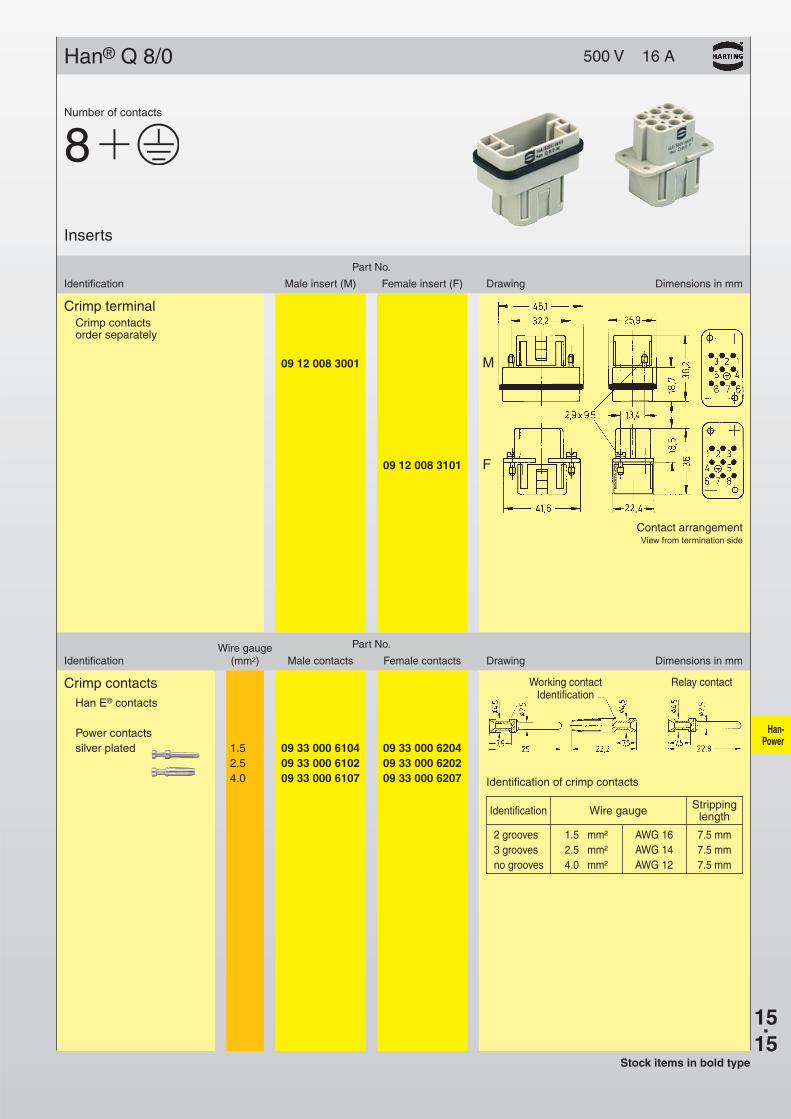
09 12 008 3101 F
09 12 008 3001 M
Han® Q 8/0 500 V 16 A
Contact arrangementView from termination side
Crimp terminalCrimp contactsorder separately
Part No.
Identification Male insert (M) Female insert (F) Drawing Dimensions in mm
Inserts
Number of contacts
8
Wire gauge Part No.
Identification (mm2) Male contacts Female contacts Drawing Dimensions in mm
Crimp contactsHan E® contacts
Power contactssilver plated 1.5 09 33 000 6104 09 33 000 6204
2.5 09 33 000 6102 09 33 000 62024.0 09 33 000 6107 09 33 000 6207
Working contactIdentification
Relay contact
Stock items in bold type
StrippingIdentification Wire gauge length
2 grooves 1.5 mm² AWG 16 7.5 mm3 grooves 2.5 mm² AWG 14 7.5 mmno grooves 4.0 mm² AWG 12 7.5 mm
Identification of crimp contacts
Han-Power
15.16
Han® Q 4/2 400/690 V 40 A
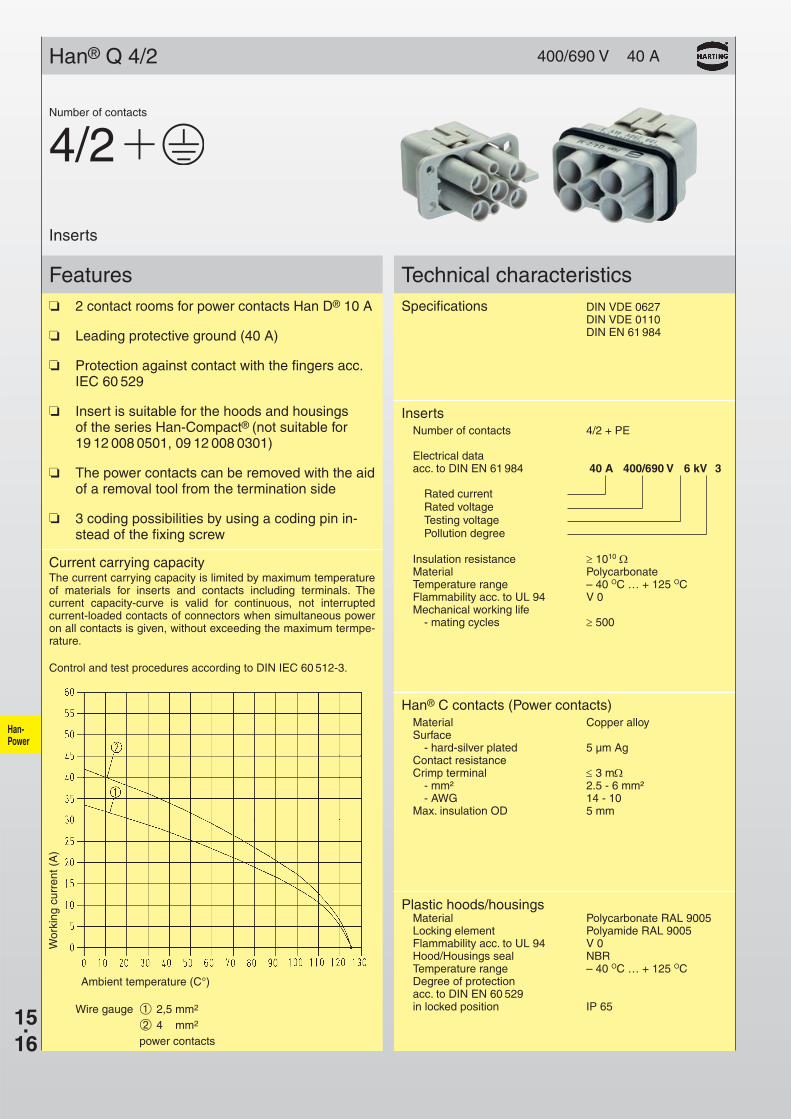
Features Technical characteristics❏ 2 contact rooms for power contacts Han D® 10 A
❏ Leading protective ground (40 A)
❏ Protection against contact with the fingers acc.IEC 60 529
❏ Insert is suitable for the hoods and housingsof the series Han-Compact® (not suitable for19 12 008 0501, 09 12 008 0301)
❏ The power contacts can be removed with the aidof a removal tool from the termination side
❏ 3 coding possibilities by using a coding pin in-stead of the fixing screw
Current carrying capacityThe current carrying capacity is limited by maximum temperatureof materials for inserts and contacts including terminals. Thecurrent capacity-curve is valid for continuous, not interruptedcurrent-loaded contacts of connectors when simultaneous poweron all contacts is given, without exceeding the maximum termpe-rature.
Control and test procedures according to DIN IEC 60 512-3.
Wor
king
cur
rent
(A
)
Ambient temperature (C°)
Wire gauge ➀ 2,5 mm2
➁ 4,0 mm2
power contacts
Specifications DIN VDE 0627DIN VDE 0110DIN EN 61 984
InsertsNumber of contacts 4/2 + PE
Electrical dataacc. to DIN EN 61 984 40 A 400/690 V 6 kV 3
Rated currentRated voltageTesting voltagePollution degree
Insulation resistance ≥ 1010 ΩMaterial PolycarbonateTemperature range – 40 OC … + 125 OCFlammability acc. to UL 94 V 0Mechanical working life
- mating cycles ≥ 500
Han® C contacts (Power contacts)Material Copper alloySurface
- hard-silver plated 5 µm AgContact resistanceCrimp terminal ≤ 3 mΩ
- mm² 2.5 - 6 mm²- AWG 14 - 10
Max. insulation OD 5 mm
Plastic hoods/housingsMaterial Polycarbonate RAL 9005Locking element Polyamide RAL 9005Flammability acc. to UL 94 V 0Hood/Housings seal NBRTemperature range – 40 OC … + 125 OCDegree of protection acc. to DIN EN 60 529in locked position IP 65
Inserts
Number of contacts
4/2

Han-Power
15.17
Han® Q 4/2
09 12 006 3141 F
09 12 006 3041 M
400/690 V 40 A
Crimp terminalOrder crimp contactsseparately
Part No.
Identification Male insert (M) Female insert (F) Drawing Dimensions in mm
Inserts
Number of contacts
4/2
Wire gauge Part No.
Identification (mm²) Male contacts Female contacts Drawing Dimensions in mm
Stock items in bold type
Crimp contactsHan D® contactsPower contacts
0.14-0.37 09 15 000 6104 09 15 000 62040.5 09 15 000 6103 09 15 000 6203
silver plated 0.75 09 15 000 6105 09 15 000 62051.0 09 15 000 6102 09 15 000 62021.5 09 15 000 6101 09 15 000 62012.5 09 15 000 6106 09 15 000 6206
StrippingWire gauge ø length
0.14-0.37 mm2 AWG 26-22 0.90 mm 8 mm0.5 mm2 AWG 20 1.10 mm 8 mm0.75 mm2 AWG 18 1.30 mm 8 mm1. mm2 AWG 18 1.45 mm 8 mm1.5 mm2 AWG 16 1.75 mm 8 mm2.5 mm2 AWG 14 2.25 mm 6 mm
Crimp contactsHan C® contactsPower contacts
2.5 09 32 000 6105 09 32 000 6205silver plated 4.0 09 32 000 6107 09 32 000 6207
6.0 09 32 000 6108 09 32 000 6208 StrippingWire gauge ø length
2.5 mm² AWG 14 2.25 9.04.0 mm² AWG 12 2.85 9.66.0 mm² AWG 10 3.50 9.6
Contact arrangement
View fromtermination side
Han-Power
15.18
Contact arrangement 1 2 3 4 5 6 7 8 PE
Identification
Technical characteristics
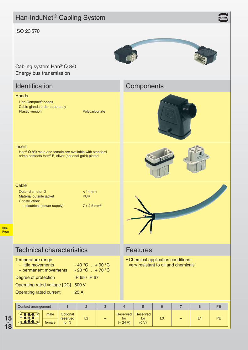
Han-InduNet® Cabling System
ComponentsHoods
Han-Compact® hoodsCable glands order separatelyPlastic version Polycarbonate
Temperature range– little movements - 40 °C … + 90 °C– permanent movements - 20 °C … + 70 °C
Degree of protection IP 65 / IP 67
Operating rated voltage [DC] 500 V
Operating rated current 25 A
Features● Chemical application conditions:
very resistant to oil and chemicals
Cabling system Han® Q 8/0Energy bus transmission
ISO 23 570
InsertHan® Q 8/0 male and female are available with standard crimp contacts Han® E, silver (optional gold) plated
CableOuter diameter D < 14 mmMaterial outside jacket PURConstruction:
– electrical (power supply) 7 x 2.5 mm²
Optional Reserved Reservedreserved L2 – for for L3 – L1 PE
for N (+ 24 V) (0 V)
male
female

Han-Power
15.19
Identification
Technical characteristics
Han-InduNet® Cabling System
ComponentsHoods
Han-Compact® hoodsCable glands order separatelyPlastic version Polycarbonate
Temperature range– little movements - 40 °C … + 90 °C– permanent movements - 20 °C … + 70 °C
Degree of protection IP 65 / IP 67
Operating rated voltage [DC] 400/690 V
Operating rated current 25 A
Features● Chemical application conditions:
very resistant to oil and chemicals
Cabling system Han® Q 4/2Energy bus transmission
InsertHan® Q 4/2 male and female are available with standard crimp contacts Han® C, silver (optional gold) plated
CableOuter diameter D < 14 mmMaterial outside jacket PURConstruction:
– electrical (power supply) 5 x 4.0 mm²
Contact arrangement 1 2 3 4 11 12 PE
Reserved ReservedL1 L2 L3 N for for PE
(0 V) (+ 24 V)
male
female
ISO 23 570
Han-Power
15.20
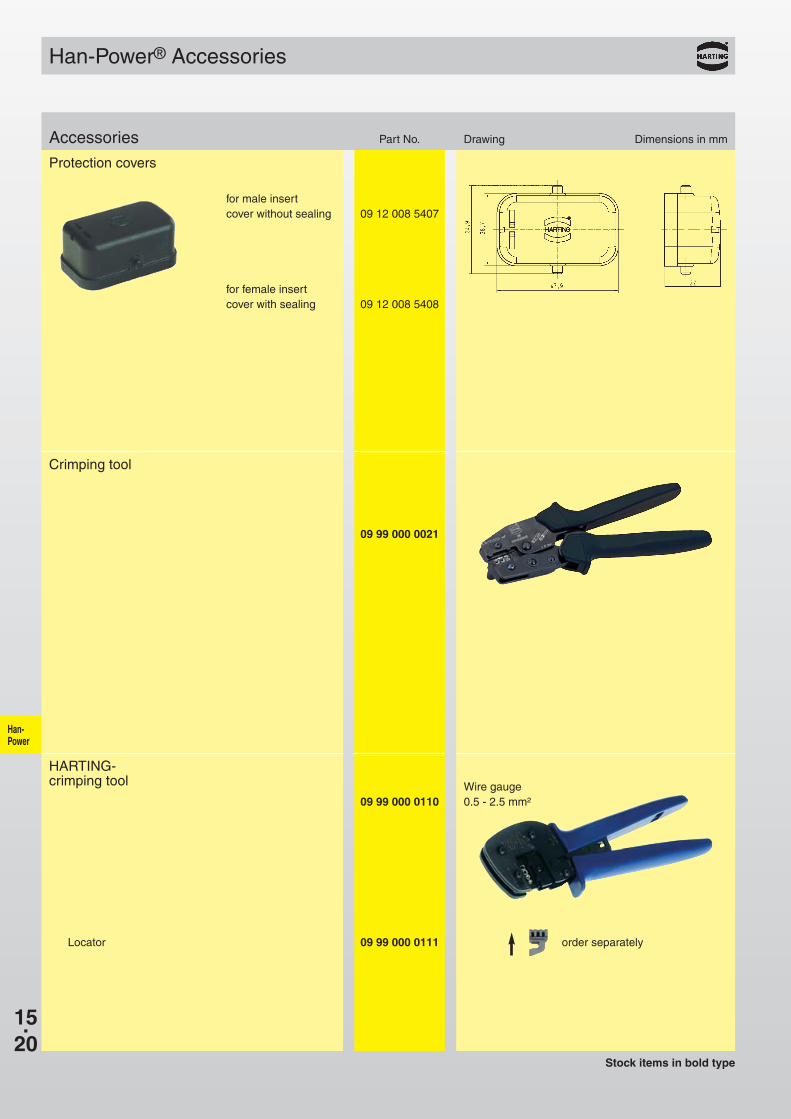
09 12 008 5407
09 12 008 5408
09 99 000 0021
09 99 000 0110
Han-Power® Accessories
Stock items in bold type
Protection covers
Accessories Part No. Drawing Dimensions in mm
for male insertcover without sealing
for female insertcover with sealing
09 99 000 0111 order separatelyLocator
Crimping tool
Wire gauge0.5 - 2.5 mm²
HARTING-crimping tool