
Analysis of Power Supply Operation in a Typical Nigerian ...
Upload
truonghanhCategory
view
216download
1
CONTENTS:
ECONOMIC WATER COOLING
TYPICAL OPERATION ARRANGEMENTS
CONTROL BY BYPASS VALVE
SINGLE VFD CONRTOLLED PUMP SYSTEM
MULTI PUMP SYSTEMS
DOUBLE PUMP SYSTEMS
SPECIAL SITUATIONS
PRIMARY / SECONDARY COOLING SYSTEMS
AIR-CONDITIONING AND COOLING/FREEZING INSTALLATIONS
WINTER OPERATION
EEX OPERATIONS (EXPLOSION PROOF)
ECONOMIC WATER COOLING
As the driving force for the cooling tower is the circulation pump set, the designing and selection is of great importance.
The AQUAFAN cooling tower can be regulated exactly to process and climatic conditions, if the process load and/or the climatic situations are within the design criteria.
The effective energy consumption is in relation to the constant or fluctuating thermal load of the installation and the fluctuating behavior of the Wet bulb Temperature (WBT).
AQUAFAN towers operate against the basic hydrodynamic laws.
= The flow rate is proportional to the speed.
HH
= ( )2 The pump head is in square law ratio to the speed.
PP
= ( )3 The power consumption is cubic law ratio to the speed.
P= Q x H/ η The energy consumption is mass x pressure / efficiency. The liquid is always water with specific weight of 1 kg/dm3
The AQUAFAN cooling tower is regulated towards a constant Cold Water Temperature (CWT).
Compared to conventional electrical driven cooling towers, there are the following advantages:
A: Full thermal load and max. Wet Bulb Temperature. Both the conventional cooling towers and AQUAFAN towers use in theory the same amount of energy. The accumulated efficiency losses over electromotors and gear drives surpass the efficiency loss in turbines.
B: Half thermal load and max. Wet Bulb Temperature. In conventional towers there are two options:
• Shut down half of the tower means 100% fan energy consumption on the operating towers + 50% on the circulation pumps.
• Operate the full tower at 2/3 or half of the fan speed means an energy consumption of 12.5% + 50% on the circulation pumps.
The water flow in nozzle or drip tray operated cooling towers can’t vary much because of the wettening efficiency, which can drop down the total tower efficiency. The half speed is only given here as an example, but in practice cannot be applied often. A more favorable possibility is a 2/3 speed with multi-stage motors or other, mostly mechanical controls. In general multistage motors are expensive and maintenance intensive. ln practice it is known that these controls, especially in these applications, cause many faults.
In AQUAFAN towers. Half of the flow means half the fan speed and half the water flow. This is an over-all energy consumption of 12.5%. Variations in flow have hardly impact on the wettening efficiency of the infill.
C: In combination with the fluctuating Wet Bulb Temperature:
In conventional towers: The fan energy consumption can reduce to “0”, while the water flow remains at
100%
In AQUAFAN towers. In general 70% of the year the AQUAFAN towers operate on less than 50% of the circulating volume to maintain the design CWT at fluctuating WBT. Aquafan Cooling Towers operate solely to the Cold Water Temperature (CWT) and Wet Bulb Temperature (WBT) relationship of the cooling tower. When the WBT is below the design condition, in theory the water flow can be reduced to keep the CWT on the design parameter, provided there is a constant heat load. In general the control system of an AQUAFAN cooling tower is based on one or a double temperature sensor, mostly a PT100 to give a signal to a PLC or converter. The PLC or converter regulates the pump condition to the setting point for the CWT.
TYPICAL OPERATION ARRANGEMENTS:
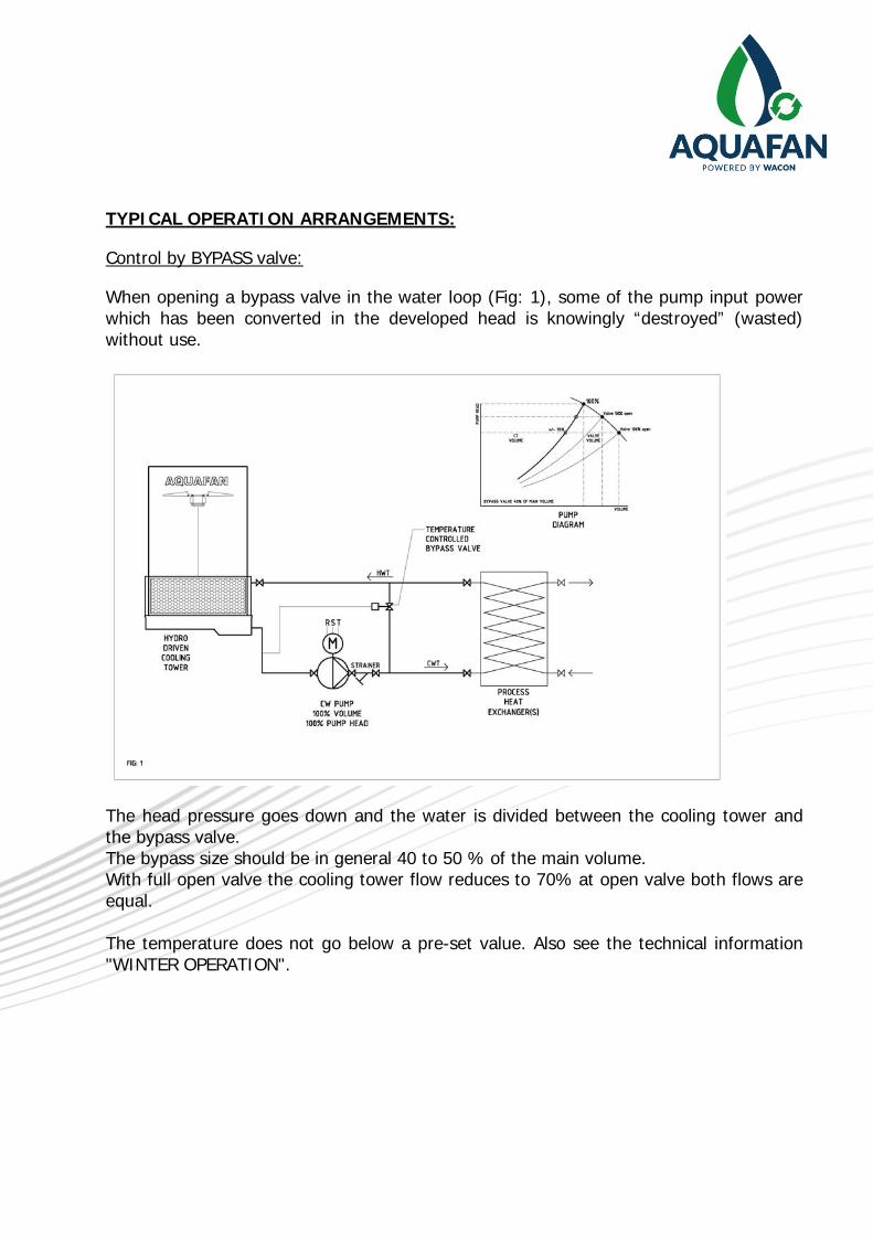
Control by BYPASS valve:
When opening a bypass valve in the water loop (Fig: 1), some of the pump input power which has been converted in the developed head is knowingly “destroyed” (wasted) without use.
The head pressure goes down and the water is divided between the cooling tower and the bypass valve. The bypass size should be in general 40 to 50 % of the main volume. With full open valve the cooling tower flow reduces to 70% at open valve both flows are equal. The temperature does not go below a pre-set value. Also see the technical information "WINTER OPERATION".
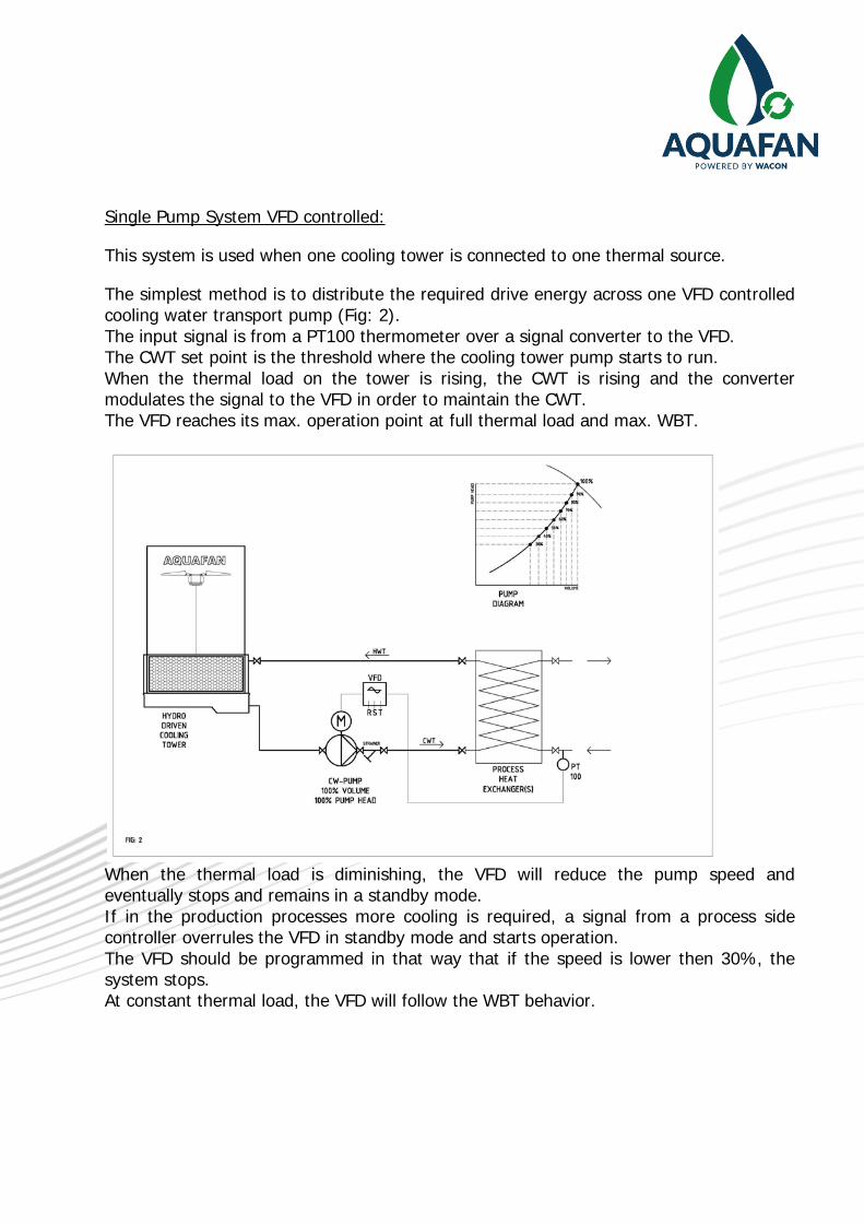
Single Pump System VFD controlled:
This system is used when one cooling tower is connected to one thermal source.
The simplest method is to distribute the required drive energy across one VFD controlled cooling water transport pump (Fig: 2). The input signal is from a PT100 thermometer over a signal converter to the VFD. The CWT set point is the threshold where the cooling tower pump starts to run. When the thermal load on the tower is rising, the CWT is rising and the converter modulates the signal to the VFD in order to maintain the CWT. The VFD reaches its max. operation point at full thermal load and max. WBT.
When the thermal load is diminishing, the VFD will reduce the pump speed and eventually stops and remains in a standby mode. If in the production processes more cooling is required, a signal from a process side controller overrules the VFD in standby mode and starts operation. The VFD should be programmed in that way that if the speed is lower then 30%, the system stops. At constant thermal load, the VFD will follow the WBT behavior.
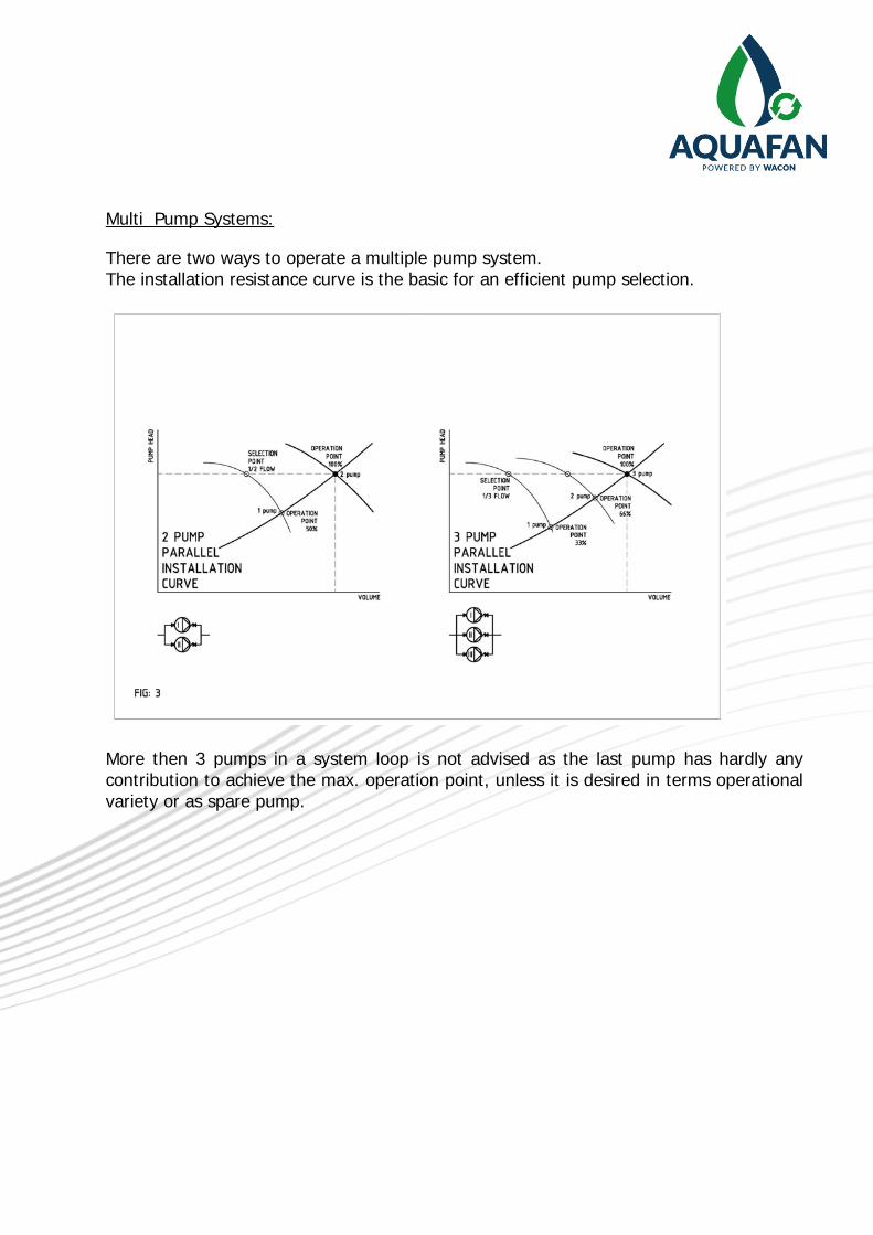
Multi Pump Systems:
There are two ways to operate a multiple pump system. The installation resistance curve is the basic for an efficient pump selection.
More then 3 pumps in a system loop is not advised as the last pump has hardly any contribution to achieve the max. operation point, unless it is desired in terms operational variety or as spare pump.
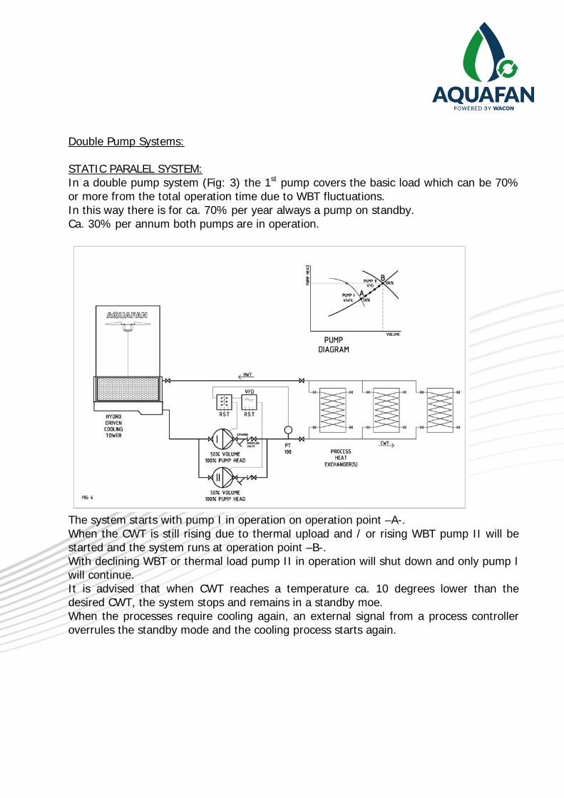
Double Pump Systems: STATIC PARALEL SYSTEM: In a double pump system (Fig: 3) the 1st pump covers the basic load which can be 70% or more from the total operation time due to WBT fluctuations. In this way there is for ca. 70% per year always a pump on standby. Ca. 30% per annum both pumps are in operation.
The system starts with pump I in operation on operation point –A-. When the CWT is still rising due to thermal upload and / or rising WBT pump II will be started and the system runs at operation point –B-. With declining WBT or thermal load pump II in operation will shut down and only pump I will continue. It is advised that when CWT reaches a temperature ca. 10 degrees lower than the desired CWT, the system stops and remains in a standby moe. When the processes require cooling again, an external signal from a process controller overrules the standby mode and the cooling process starts again.
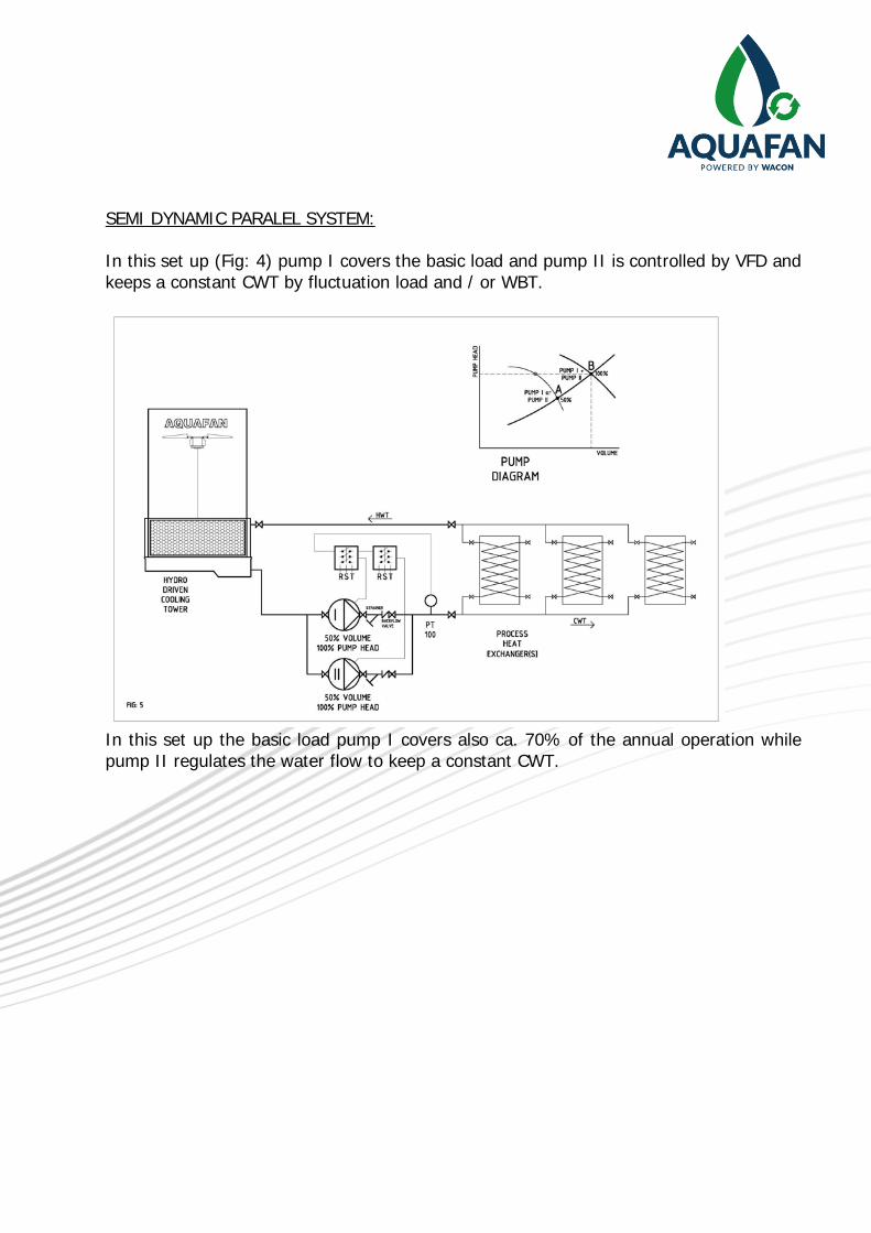
SEMI DYNAMIC PARALEL SYSTEM: In this set up (Fig: 4) pump I covers the basic load and pump II is controlled by VFD and keeps a constant CWT by fluctuation load and / or WBT.
In this set up the basic load pump I covers also ca. 70% of the annual operation while pump II regulates the water flow to keep a constant CWT.

FULL DYNAMIC PARALEL SYSTEM: In this set up (Fig: 5) pump I & II are controlled by VFD and keep a constant CWT by fluctuation load and / or WBT.
This is the most economic way to operate AQUAFAN cooling towers. Both pumps are controlled to hold the CWT over the whole range at minimum energy consumption.
SPECIAL SITUATIONS:
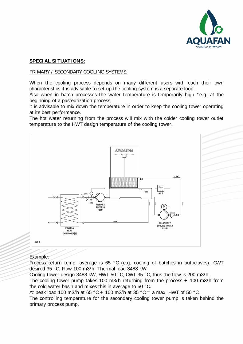
PRIMARY / SECONDARY COOLING SYSTEMS:
When the cooling process depends on many different users with each their own characteristics it is advisable to set up the cooling system is a separate loop. Also when in batch processes the water temperature is temporarily high *e.g. at the beginning of a pasteurization process, it is advisable to mix down the temperature in order to keep the cooling tower operating at its best performance. The hot water returning from the process will mix with the colder cooling tower outlet temperature to the HWT design temperature of the cooling tower.
Example: Process return temp. average is 65 °C (e.g. cooling of batches in autoclaves). CWT desired 35 °C. Flow 100 m3/h. Thermal load 3488 kW. Cooling tower design 3488 kW, HWT 50 °C, CWT 35 °C, thus the flow is 200 m3/h. The cooling tower pump takes 100 m3/h returning from the process + 100 m3/h from the cold water basin and mixes this in average to 50 °C. At peak load 100 m3/h at 65 °C + 100 m3/h at 35 °C = a max. HWT of 50 °C. The controlling temperature for the secondary cooling tower pump is taken behind the primary process pump.
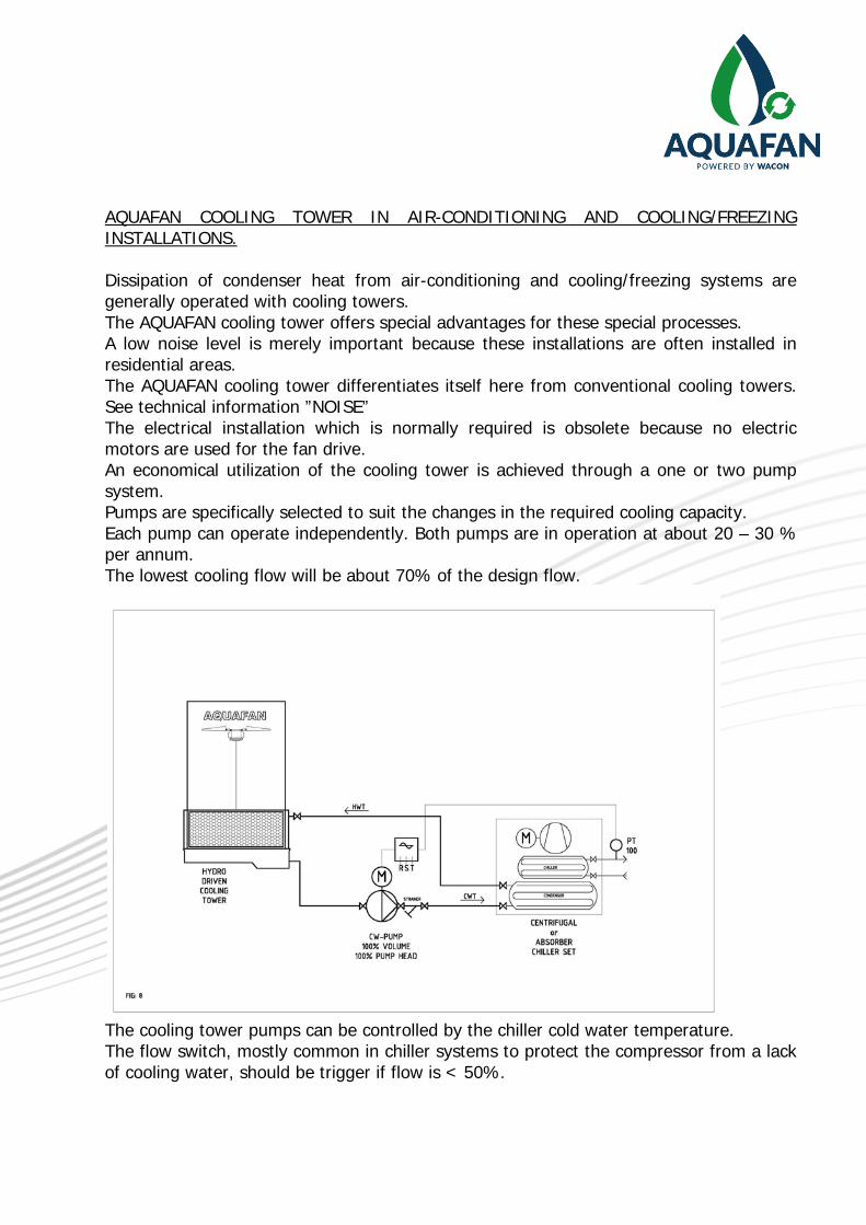
AQUAFAN COOLING TOWER IN AIR-CONDITIONING AND COOLING/FREEZING INSTALLATIONS. Dissipation of condenser heat from air-conditioning and cooling/freezing systems are generally operated with cooling towers. The AQUAFAN cooling tower offers special advantages for these special processes. A low noise level is merely important because these installations are often installed in residential areas. The AQUAFAN cooling tower differentiates itself here from conventional cooling towers. See technical information ”NOISE” The electrical installation which is normally required is obsolete because no electric motors are used for the fan drive. An economical utilization of the cooling tower is achieved through a one or two pump system. Pumps are specifically selected to suit the changes in the required cooling capacity. Each pump can operate independently. Both pumps are in operation at about 20 – 30 % per annum. The lowest cooling flow will be about 70% of the design flow.
The cooling tower pumps can be controlled by the chiller cold water temperature. The flow switch, mostly common in chiller systems to protect the compressor from a lack of cooling water, should be trigger if flow is < 50%.

WINTER OPERATION
Aquafan cooling towers are low temperature resistant. The cooling towers can freeze and thaw up automatically without any damage, however external aspects need to be taken in consideration. Freezing of a cooling tower occurs when water is running without any heat load in a freezing environment. During standstill of the fans, icing occurs due to freezing fog. The infill intents to fully clog with ice. The air inlet screens freeze up. Typical problems occur in seasonal winter times at morning dawn. It is advised to shut down water circulation when the water reaches 5 °C or 40 °F, if there is no or minor thermal load. The proportional controlling of the water and air is the simple solution to overcome these difficulties. Starting a frozen AQUAFAN cooling tower is no problem. The relatively warm cooling water coming into the tower will thaw up the turbine and fan assembly and later the infill and inlets. No damage will occur during freezing or start up.
Winter precautions: -A-: Tracing of outside piping where water remains.

-B-: Concrete sump with the bottom below the freezing depth of the soil, with covered pump compartment.
-C-: When the pump stops for a longer period, an automatic drain device is required. -D-: Auto drain of main pipe during stand still. -E-: Partially coverable inlet screens (e.g planes or wooden plates). Mostly covering the
wind side of the tower is already sufficient. We can provide inlet screens with manual or automatic shutters to close the air inlet when required.
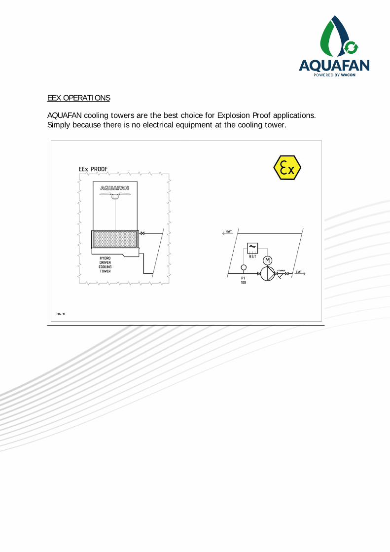
EEX OPERATIONS
AQUAFAN cooling towers are the best choice for Explosion Proof applications. Simply because there is no electrical equipment at the cooling tower.


![Successful Bunched Beam Stochastic Cooling · operation.[l] Cooling is the only remedy for the effects of Intra-Beam Scattering and both electron cooling[2] and stochastic cooling](https://static.fdocuments.us/doc/165x107/6004f751948bec79cd0afc1d/successful-bunched-beam-stochastic-cooling-operationl-cooling-is-the-only-remedy.jpg)


