Contents Asset Library/Pneumatic Valves-Valve... · EtherNET/IPTM DLR, EtherCAT®, POWERLINK,...
12
ATEX Contents 01450GB-2017/R02 Availability, design and specifications are subject to change without notice. All rights reserved. Series 502 Valve Islands Series 502, ATEX Group II, Zone 2 and 22, Category 3 GD Features ........................................................................ 168..170 Specifications ..................................................................... 171-172 How to Order - Assembly Kit ............................................................ 173 How to Order - Subbases / Valves ........................................................ 174 How to Order - Accessories ............................................................. 175 How to Order - G3 Electronics ........................................................... 176 How to Order - Connectors .............................................................. 177 ATEX certification ..................................................................... 183 All leaflets are available on: www.asco.com Fielbus Electronics - 167
Transcript of Contents Asset Library/Pneumatic Valves-Valve... · EtherNET/IPTM DLR, EtherCAT®, POWERLINK,...

ATEXContents
0145
0GB
-201
7/R
02A
vaila
bilit
y, d
esig
n an
d sp
ecifi
catio
ns a
re s
ubje
ct to
cha
nge
with
out n
otic
e. A
ll rig
hts
rese
rved
.
Series 502 Valve
Islands Series 502, ATEX Group II, Zone 2 and 22, Category 3 GD Features . . . . . . . . . . . . . . . . . . . . . . . . . . . . . . . . . . . . . . . . . . . . . . . . . . . . . . . . . . . . . . . . . . . . . . . . 168..170
Specifications . . . . . . . . . . . . . . . . . . . . . . . . . . . . . . . . . . . . . . . . . . . . . . . . . . . . . . . . . . . . . . . . . . . . . 171-172
How to Order - Assembly Kit . . . . . . . . . . . . . . . . . . . . . . . . . . . . . . . . . . . . . . . . . . . . . . . . . . . . . . . . . . . . 173
How to Order - Subbases / Valves . . . . . . . . . . . . . . . . . . . . . . . . . . . . . . . . . . . . . . . . . . . . . . . . . . . . . . . . 174
How to Order - Accessories . . . . . . . . . . . . . . . . . . . . . . . . . . . . . . . . . . . . . . . . . . . . . . . . . . . . . . . . . . . . . 175
How to Order - G3 Electronics . . . . . . . . . . . . . . . . . . . . . . . . . . . . . . . . . . . . . . . . . . . . . . . . . . . . . . . . . . . 176
How to Order - Connectors . . . . . . . . . . . . . . . . . . . . . . . . . . . . . . . . . . . . . . . . . . . . . . . . . . . . . . . . . . . . . . 177
ATEX certification . . . . . . . . . . . . . . . . . . . . . . . . . . . . . . . . . . . . . . . . . . . . . . . . . . . . . . . . . . . . . . . . . . . . . 183
All leaflets are available on: www.asco.com
Fielbus Electronics - 167

Series 502 Valve
Manifolds of 502 series valves are equipped with integral electrical plug-in allowing an easy exchange of single components without dismounting the manifold.“Z-Board”™ eliminates internal wiring.Manifolds are available with threaded ports.Exhaust ports 12 and 14 are integrated in the base with common exhaust at port 12.
Technical Data • Operating Data
0145
0GB
-201
7/R
02A
vaila
bilit
y, d
esig
n an
d sp
ecifi
catio
ns a
re s
ubje
ct to
cha
nge
with
out n
otic
e. A
ll rig
hts
rese
rved
.Picture shows single solenoid pilot actuated 5-port., 2-pos. valve mounted on manifold
Integral Recessed Gaskets between Manifolds
Manual Override (impulse-type, push-turn type,
Low WattagePlug-in Solenoid
Base with integral “Z-Board”™
eliminates internal wiring!
Plug-in System Valve/Base
Rubber Packed Technology
LED indicates when power is supplied
to solenoid
Threaded Ports
Valve Body Integral Recessed Gasket provides Positive Sealing
All leaflets are available on: www.asco.com
168 - Fielbus Electronics
ATEX

ATEXSeries 502 Multipole Connectors ATEX
Multipole Connectors • General Information
FEATURES• Solenoid air operated valve manifolds for connection to a control system
(PLC) with a multiwire cable for simple wiring.• Electrical connection with a 25 or 37 pin Sub-D connector or a 19 pin round
connector, or with terminal strip.• Internal wiring by “Z-Board“ plug-in system.• Plug-together flexibility due to different assembly and wiring options.• Designed to meet IP65 with round connector or terminal strip.
COMBINATIONS• The maximum number of valves depends on the type of electrical
connection chosen:502
input modules (1)
(G3/ATEX) max. coils (1)
0 31
1 29
2 26
3 24
4 22
580 (2) 13580 CHARMs 32
25 Pin Sub-D Connector
1537 Pin Sub-D ConnectorTerminal Strip 1-32
19 Pin Round Connector (1) Do not exceed the max. number of pilot solenoid valves authorised.
(2) DeviceNetTM, PROFIBUS-DP®, CANopen®, PROFINET®, SUB-BUS node, EtherNET/IPTM, EtherNET/IPTM DLR, EtherCAT®, POWERLINK, IO-Link Class A, IO-Link Class B
• The valve manifolds are intended for frame or DIN-EN 50022 rail mounting.
0145
0GB
-201
8/R
01A
vaila
bilit
y, d
esig
n an
d sp
ecifi
catio
ns a
re s
ubje
ct to
cha
nge
with
out n
otic
e. A
ll rig
hts
rese
rved
.
All leaflets are available on: www.asco.com
Fielbus Electronics - 169
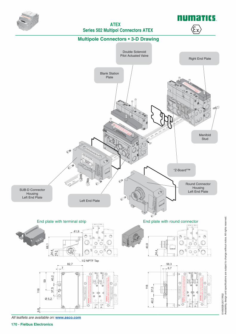
Multipole Connectors • 3-D Drawing
0145
0GB
-201
7/R
02A
vaila
bilit
y, d
esig
n an
d sp
ecifi
catio
ns a
re s
ubje
ct to
cha
nge
with
out n
otic
e. A
ll rig
hts
rese
rved
.
ll 3G Ex nA llC T4 Gc IP65 X
ll 3D Ex tc lllC T85°C Dc IP65 X
Tech. file ref.
BP17 28111 Luce Cedex France
T° amb C
Max P. - 8 bar
Option
Year
SERIAL N°
WARNING : SPECIFIC CONDITIONS OF USE
- SEE INSTRUCTIONS --
Blank Station Plate
ManifoldStud
Round Connector Housing
Left End Plate
Left End Plate
SUB-D Connector Housing
Left End Plate
“Z-Board”™
Right End Plate
Double Solenoid Pilot Actuated Valve
118
56,3
40,8
37,5
40,2
6,7
24,4
WARN
ING : D
O NOT
SEPA
RATE
PLUG
S AND
SOCK
ETS W
HEN E
NERG
IZED
POTE
NTIAL
ELEC
TROS
TATIC
CHAR
GING H
AZAR
D : RE
FER T
O INS
TRUC
TIONS
WARN
ING :
REFE
RT TO
INST
RUCT
IONS
FOR M
OUNT
ING
AND
FOR M
AX N
UMBE
R OF C
OILS
SIM
ULTA
NEOU
SLY E
NERG
IZED
41,9
68,1
24,4
19,3
82,77
40,2
59
37,5
118
9,8
Ø 5,2
1/2 NPTF Tap
WARN
ING : D
O NOT
SEPA
RATE
PLUG
S AND
SOCK
ETS W
HEN E
NERG
IZED
POTE
NTIAL
ELEC
TROS
TATIC
CHAR
GING H
AZAR
D : RE
FER T
O INS
TRUC
TIONS
WARN
ING :
REFE
RT TO
INST
RUCT
IONS
FOR M
OUNT
ING
AND
FOR M
AX N
UMBE
R OF C
OILS
SIM
ULTA
NEOU
SLY E
NERG
IZED
End plate with terminal strip End plate with round connector
Series 502 Multipol Connectors ATEX
All leaflets are available on: www.asco.com
170 - Fielbus Electronics
ATEX
ATEX502 Series
0145
0GB
-201
7/R
02A
vaila
bilit
y, d
esig
n an
d sp
ecifi
catio
ns a
re s
ubje
ct to
cha
nge
with
out n
otic
e. A
ll rig
hts
rese
rved
.
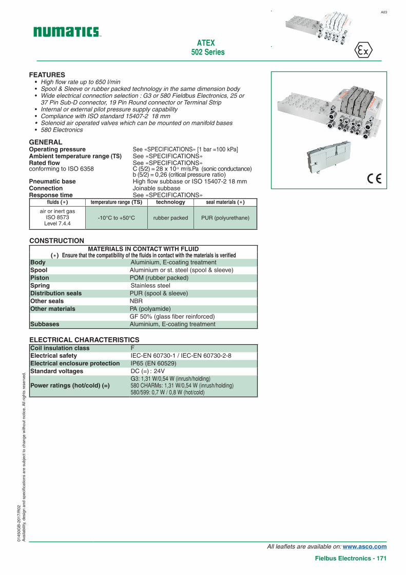
FEATURES• High flow rate up to 650 l/min• Spool & Sleeve or rubber packed technology in the same dimension body• Wide electrical connection selection : G3 or 580 Fieldbus Electronics, 25 or
37 Pin Sub-D connector, 19 Pin Round connector or Terminal Strip• Internal or external pilot pressure supply capability• Compliance with ISO standard 15407-2 18 mm• Solenoid air operated valves which can be mounted on manifold bases• 580 Electronics
GENERAL Operating pressure See «SPECIFICATIONS» [1 bar =100 kPa]Ambient temperature range (TS) See «SPECIFICATIONS»Rated flow See «SPECIFICATIONS» conforming to ISO 6358 C (5/2) = 28 x 10-9 m3/s.Pa (sonic conductance)
b (5/2) = 0,26 (critical pressure ratio)Pneumatic base High flow subbase or ISO 15407-2 18 mmConnection Joinable subbaseResponse time See «SPECIFICATIONS»
fluids () temperature range (TS) technology seal materials ()
air or inert gasISO 8573
Level 7.4.4-10°C to +50°C rubber packed PUR (polyurethane)
CONSTRUCTIONMATERIALS IN CONTACT WITH FLUID
() Ensure that the compatibility of the fluids in contact with the materials is verifiedBody Aluminium, E-coating treatmentSpool Aluminium or st. steel (spool & sleeve)Piston POM (rubber packed)Spring Stainless steelDistribution seals PUR (spool & sleeve)Other seals NBROther materials PA (polyamide)
GF 50% (glass fiber reinforced)Subbases Aluminium, E-coating treatment
ELECTRICAL CHARACTERISTICSCoil insulation class FElectrical safety IEC-EN 60730-1 / IEC-EN 60730-2-8Electrical enclosure protection IP65 (EN 60529)Standard voltages DC (=) : 24V
Power ratings (hot/cold) (=)G3: 1,31 W/0,54 W (inrush/holding)580 CHARMs: 1,31 W/0,54 W (inrush/holding)580/599: 0,7 W / 0,8 W (hot/cold)
A03
All leaflets are available on: www.asco.com
Fielbus Electronics - 171

502 Series
SPECIFICATIONS 15-DIGIT PRODUCT CODE
function type
symbolrated flow
response time
open / closed
pilot pressure
at 23°C(bar)
operating pressureport 1
at 6,3 bar ∆P 1 barl/min (ANR)
min.
max. (PS)
pilot (14)return (12)
air ()1 21 4
2 34 5 (ms) min. max. =
SPOOL VALVE, RUBBER PACKED TECHNOLOGY, WITH IMPULSE MANUAL OPERATOR
2 x 3/2NC
K
14 1210 10
83(12)14
5
4
3
2
1spring H
igh
flow
sub
base
650 600 36 / 15 4 8 2 (**) 8 R502A2BD0M71WF1
0145
0GB
-201
8/R
01A
vaila
bilit
y, d
esig
n an
d sp
ecifi
catio
ns a
re s
ubje
ct to
cha
nge
with
out n
otic
e. A
ll rig
hts
rese
rved
.
SPECIFICATIONS 15-DIGIT PRODUCT CODE
function type
symbolrated flow
response time
open / closed
pilot pressure
at 23°C(bar)
operating pressureport 1
at 6,3 bar ∆P 1 barl/min (ANR)
min.
max. (PS)
pilot (14)return (12)
air ()1 21 4
2 34 5 (ms) min. max. =
SPOOL VALVE, SPOOL AND SLEEVE TECHNOLOGY, WITH IMPULSE MANUAL OPERATOR
5/2
S1
4 2
3514 83(12)
spring Hig
h flo
w s
ubba
se
470 530 16 / 49 2 8 -0,95 8 R502A1B10M71WF1
M 1
4 2
3514(12)83
differential return Hig
h flo
w s
ubba
se
470 530 11 / 26 1,5 8 -0,95 8 R502A1BN0N71WF1
J 1
4 2
3514(12)83
solenoid air Hig
h flo
w s
ubba
se
470 530 16 / 16 2 8 -0,95 8 R502A1B40M71WF1
5/3
G 1
4 2
3514(12)83
W1
closed centre position Hig
h flo
w s
ubba
se
420 440 12 / 12 1,5 8 -0,95 8 R502A1B60M71WF1
B 1
4 2
3514(12)83
W2centre open to pressure H
igh
flow
sub
base
420 430 13 / 23 1,5 8 -0,95 8 R502A1B70M71WF1
E 1
4 2
3514(12)83
W3centre open to exhaust H
igh
flow
sub
base
380 500 23 / 13 1,5 8 -0,95 8 R502A1B50M F1
() Vérifier la compatibilité du fluide avec les matériaux en contact.
(**) Min. pressure with external piloting.
All leaflets are available on: www.asco.com
172 - Fielbus Electronics
ATEX

ATEX502 Series
(5) Do not exceed the max. number of pilot solenoid valves authorised.
(6) DeviceNetTM, PROFIBUS-DP®, CANopen®, PROFINET®, SUB-BUS node, EtherNET/IPTM, EtherNET/IPTM DLR, EtherCAT®, POWERLINK, IO-Link Class A, IO-Link Class B
How to OrderManifold assemblies kit (Electronic + End plate)
15-DIGIT PRODUCT CODEG 502 A V 3 4 2 0 0 V A36
Thread connection ATEX optionsG = ISO 228/1 2-22 (3GD) IP65X 2-22 (3GD) IP54X 2 (3G) IP54X8 = NPT (contact us) A36 (1) A41 (1) A43 (1)
K = Push-in connectors D36 (2) D41 (2) D43 (2)
D38 (3) D42 (3) D44 (3)
F16 (4) F18 (4) F19 (4)
Product series502 (18 mm valve) (1) Internal pilot W/O DIN Rail Mount
(2) DIN Rail MountRevision letter (3) External pilot supply from port 14A = Initial release (4) External pilot supply from port 14 and
DIN Rail Mount
Product typeV = Valve Manifold Assembly End Plate Style
V = VerticalElectronics8 = 580 Fieldbus Electronics Second Valve SeriesD = CHARMs Electronics 0 = No Second Valve Series3 = G3 Fieldbus Electronics J = 25 Pin Sub-D ConnectorM = 37 Pin Sub-D ConnectorQ = 19 Pin Round Connector Valve Station AdderQ = 26 Pin Round Connector 0 = No AdderT = Terminal Strip 1-32
Number of Valve StationsB = 2 L = 12 End Plate Port Size (1-3-5)D = 4 N = 14 Used with the first digit «G» or «8»:F = 6 P = 16 3 = 3/8 (manifold base)H = 8 Used with the first digit «K»:J = 10 K = 8 x 10 mm (push-in connector)
M = 10 x 12 mm (push-in connector)
1 152 3 160, 1.. 2
input modules (5)
(G3/ATEX)502
max. coils (5)
0 311 292 263 244 22
580 (6) 13580 CHARMs 32
25 Pin Sub-D Connector
1537 Pin Sub-D Connector
Terminal Strip 1-3219 Pin Round Connector
502
0145
0GB
-201
8/R
01A
vaila
bilit
y, d
esig
n an
d sp
ecifi
catio
ns a
re s
ubje
ct to
cha
nge
with
out n
otic
e. A
ll rig
hts
rese
rved
.
Configurator - CAD Files
All leaflets are available on: www.asco.com
Fielbus Electronics - 173
ATEX502 Series
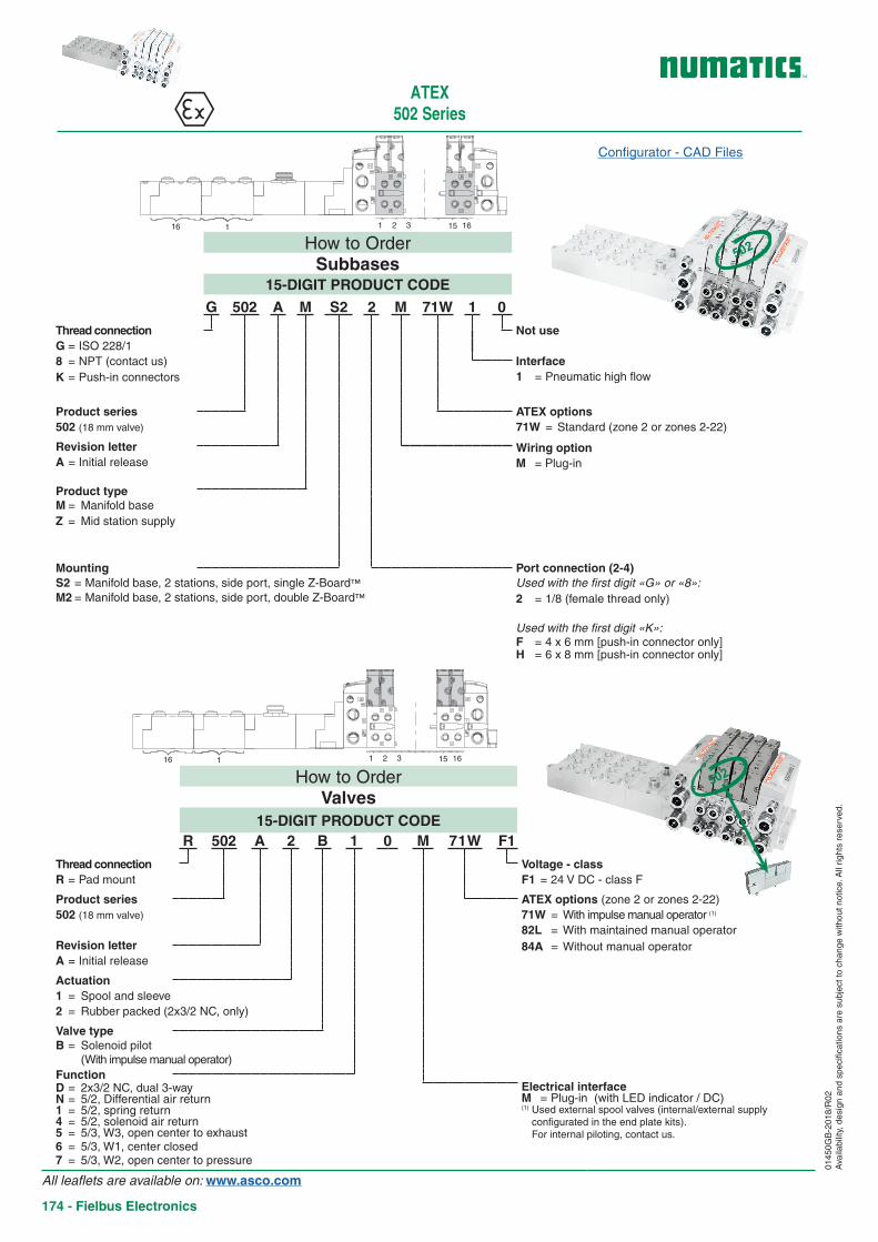
How to OrderValves
15-DIGIT PRODUCT CODER 502 A 2 B 1 0 M 71W F1
Thread connection Voltage - classR = Pad mount F1 = 24 V DC - class F
Product series ATEX options (zone 2 or zones 2-22)502 (18 mm valve) 71W = With impulse manual operator (1)
82L = With maintained manual operatorRevision letter 84A = Without manual operatorA = Initial release
Actuation1 = Spool and sleeve2 = Rubber packed (2x3/2 NC, only)
Valve typeB = Solenoid pilot
(With impulse manual operator)FunctionD = 2x3/2 NC, dual 3-way Electrical interfaceN = 5/2, Differential air return M = Plug-in (with LED indicator / DC)1 = 5/2, spring return (1) Used external spool valves (internal/external supply
configurated in the end plate kits). For internal piloting, contact us.
4 = 5/2, solenoid air return5 = 5/3, W3, open center to exhaust6 = 5/3, W1, center closed7 = 5/3, W2, open center to pressure
How to OrderSubbases
15-DIGIT PRODUCT CODE
G 502 A M S2 2 M 71W 1 0
Thread connection Not useG = ISO 228/18 = NPT (contact us) InterfaceK = Push-in connectors 1 = Pneumatic high flow
Product series ATEX options502 (18 mm valve) 71W = Standard (zone 2 or zones 2-22)
Revision letter Wiring optionA = Initial release M = Plug-in
Product typeM = Manifold base
Z = Mid station supply
Mounting Port connection (2-4)S2 = Manifold base, 2 stations, side port, single Z-Board™ Used with the first digit «G» or «8»:M2 = Manifold base, 2 stations, side port, double Z-Board™ 2 = 1/8 (female thread only)
Used with the first digit «K»:F = 4 x 6 mm [push-in connector only]H = 6 x 8 mm [push-in connector only]
16 1 1 152 3 16
16 1 1 152 3 16
502
502
0145
0GB
-201
8/R
02A
vaila
bilit
y, d
esig
n an
d sp
ecifi
catio
ns a
re s
ubje
ct to
cha
nge
with
out n
otic
e. A
ll rig
hts
rese
rved
.
Configurator - CAD Files
All leaflets are available on: www.asco.com
174 - Fielbus Electronics
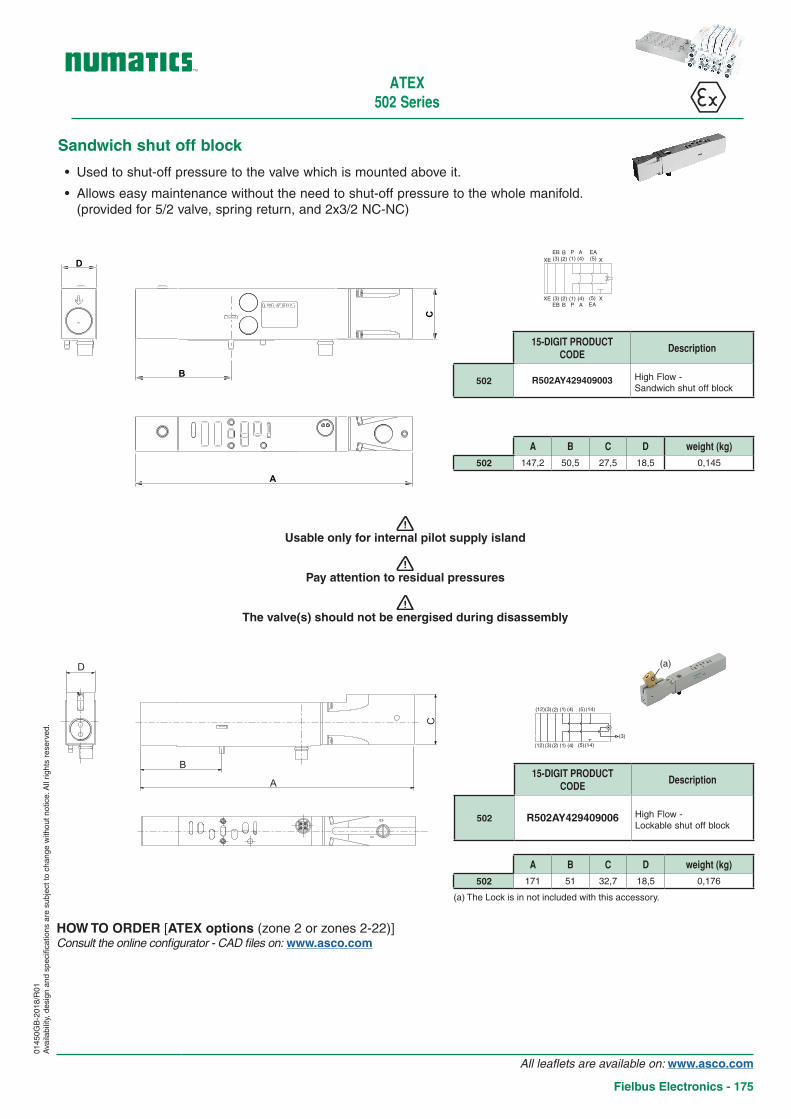
A B C D weight (kg)
502 147,2 50,5 27,5 18,5 0,145
15-DIGIT PRODUCT CODE
Description
502 R502AY429409003 High Flow - Sandwich shut off block
• Used to shut-off pressure to the valve which is mounted above it.
• Allows easy maintenance without the need to shut-off pressure to the whole manifold. (provided for 5/2 valve, spring return, and 2x3/2 NC-NC)
Sandwich shut off block
HOW TO ORDER [ATEX options (zone 2 or zones 2-22)]Consult the online configurator - CAD files on: www.asco.com
D
B
A
C
ATEX502 Series
! Usable only for internal pilot supply island
! Pay attention to residual pressures
! The valve(s) should not be energised during disassembly
0145
0GB
-201
8/R
01A
vaila
bilit
y, d
esig
n an
d sp
ecifi
catio
ns a
re s
ubje
ct to
cha
nge
with
out n
otic
e. A
ll rig
hts
rese
rved
.
15-DIGIT PRODUCT CODE
Description
502 R502AY429409006 High Flow - Lockable shut off block
D
A
C
B
A B C D weight (kg)
502 171 51 32,7 18,5 0,176
(12)(3)
(3)
(3)
(2)
(2) (1)
(1) (4)
(4) (5)
(5)(14)
(12) (14)
XE
XE
EB(3)
(3)EB
B(2)
(2)B
(1)P
P(1)
A(4)
(4)A
(5)EA
EA(5)
X
X
(a)
(a) The Lock is in not included with this accessory.
All leaflets are available on: www.asco.com
Fielbus Electronics - 175
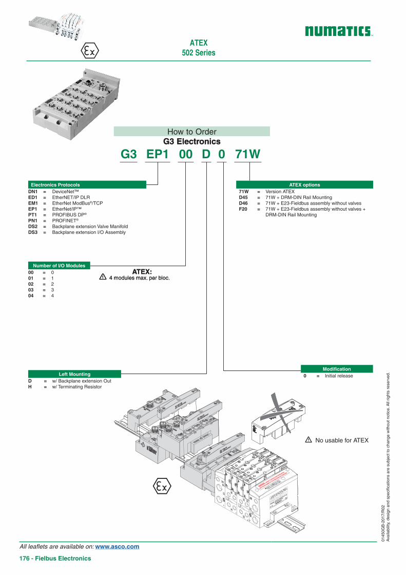
How to OrderG3 Electronics
G3 EP1 00 D 0 71W
Number of I/O Modules00 = 001 = 102 = 203 = 304 = 4
Electronics ProtocolsDN1 = DeviceNet™ED1 = EtherNET/IP DLREM1 = EtherNet ModBus®/TCPEP1 = EtherNet/IP™PT1 = PROFIBUS DP®
PN1 = PROFINET®
DS2 = Backplane extension Valve ManifoldDS3 = Backplane extension I/O Assembly
Left MountingD = w/ Backplane extension OutH = w/ Terminating Resistor
ATEX options71W = Version ATEXD45 = 71W + DRM-DIN Rail MountingD46 = 71W + E23-Fieldbus assembly without valvesF20 = 71W + E23-Fieldbus assembly without valves +
DRM-DIN Rail Mounting
Modification0 = Initial release
! 4 modules max. per bloc.ATEX:
WARNING : DO NOT SEPARATE PLUGS AND SOCKETS WHEN ENERGIZED
POTENTIAL ELECTROSTATIC CHARGING HAZARD : REFER TO INSTRUCTIONS
WARNING : DO NOT CONNECT OR DISCONNECT
PLUGS AND SOCKETS WHEN ENERGIZED
ll 3G Ex nA llC
T4 Gc IP65 X
ll 3D Ex tc lllC
T85°C Dc IP65 X
Tech. file re
f.
BP17 28111 Luce C
edex France
T° amb C
Max P. - 8 bar
Option
Year
SERIAL N
°
WARNING : SPECIFIC CONDITIONS OF USE
- SEE INSTRUCTIONS -
-
WARNING : REFERT TO INSTRUCTIONS FOR MOUNTING
AND FOR MAX NUMBER OF COILS SIMULTANEOUSLY ENERGIZED
How to OrderG3 Electronics
Number of I/O Modules00 = 001 = 102 = 203 = 304 = 4
Electronics ProtocolsDN1 = DeviceNet™ED1 = EtherNET/IP DLREM1 = EtherNet ModBus®/TCPEP1 = EtherNet/IP™PT1 = PROFIBUS DP®
PN1 = PROFINET®
DS2 = Backplane extension Valve ManifoldDS3 = Backplane extension I/O Assembly
Left MountingD = w/ Backplane extension OutH = w/ Terminating Resistor
ATEX options71W = Version ATEXD45 = 71W + DRM-DIN Rail MountingD46 = 71W + E23-Fieldbus assembly without valvesF20 = 71W + E23-Fieldbus assembly without valves +
DRM-DIN Rail Mounting
Modification0 = Initial release
! 4 modules max. par bloc.ATEX:
WARNING : DO NOT SEPARATE PLUGS AND SOCKETS WHEN ENERGIZED
POTENTIAL ELECTROSTATIC CHARGING HAZARD : REFER TO INSTRUCTIONS
WARNING : DO NOT CONNECT OR DISCONNECT
PLUGS AND SOCKETS WHEN ENERGIZED
ll 3G Ex nA llC T4 Gc IP65 X
ll 3D Ex tc lllC T85°C Dc IP65 X
Tech. file re
f.
BP17 28111 Luce C
edex France
T° amb C
Max P. - 8 bar
Option
Year
SERIAL N
°
WARNING : SPECIFIC CONDITIONS OF USE
- SEE INSTRUCTIONS -
-
WARNING : REFERT TO INSTRUCTIONS FOR MOUNTING
AND FOR MAX NUMBER OF COILS SIMULTANEOUSLY ENERGIZED
ATEX502 Series
! No usable for ATEX
0145
0GB
-201
7/R
02A
vaila
bilit
y, d
esig
n an
d sp
ecifi
catio
ns a
re s
ubje
ct to
cha
nge
with
out n
otic
e. A
ll rig
hts
rese
rved
.
All leaflets are available on: www.asco.com
176 - Fielbus Electronics

ATEX502 Series
0145
0GB
-201
7/R
02A
vaila
bilit
y, d
esig
n an
d sp
ecifi
catio
ns a
re s
ubje
ct to
cha
nge
with
out n
otic
e. A
ll rig
hts
rese
rved
.
ConnectorsAccessory type Designation Code
2 / 3 / 5 m
25 Pin Sub-D Female Connector (500 series) w/ cable
2 m NDB25F22U02MSB3
5 m NDB25F22U05MSB3
10 m NDB25F22U10MSB3
2 / 3 / 5 m
37 Pin Sub-D Female Connector (500 series) w/ cable
2 m NDB37F22U02MSB3
5 m NDB37F22U05MSB3
10 m NDB37F22U10MSB3
19 pin female M23 connector, straight (500 and 2000 series)
w/o cable 88164102
w/ cable 5 m 88164106
19 pin female M23 connector, 90° elbow (500 and 2000 series)
w/o cable 88164105
w/ cable 5 m 88164107
NDB25F22U02MSB3NDB25F22U05MSB3NDB25F22U10MSB3
Pin 1 : whitePin 2 : brownPin 3 : greenPin 4 : yellowPin 5 : greyPin 6 : pinkPin 7 : bluePin 8 : redPin 9 : blackPin 10 : purplePin 11 : grey/pinkPin 12 : red/bluePin 13 : white/greenPin 14 : brown/greenPin 15 : white/yellowPin 16 : yellow/brownPin 17 : white/greyPin 18 : grey/brownPin 19 : white/pinkPin 20 : pink/brownPin 21 : white/bluePin 22 : brown/bluePin 23 : white/redPin 24 : brown/redPin 25 : white/black
NDB37F22U02MSB3NDB37F22U05MSB3NDB37F22U10MSB3
Pin 1 : whitePin 2 : brownPin 3 : greenPin 4 : yellowPin 5 : greyPin 6 : pinkPin 7 : bluePin 8 : redPin 9 : blackPin 10 : purplePin 11 : grey/pinkPin 12 : red/bluePin 13 : white/greenPin 14 : brown/greenPin 15 : white/yellowPin 16 : yellow/brownPin 17 : white/greyPin 18 : grey/brownPin 19 : white/pinkPin 20 : pink/brownPin 21 : white/bluePin 22 : brown/bluePin 23 : white/redPin 24 : brown/redPin 25 : white/black
Pin 26 : brown/blackPin 27 : grey/greenPin 28 : yellow/greyPin 29 : pink/greenPin 30 : yellow/pinkPin 31 : green/bluePin 32 : yellow/bluePin 33 : green/redPin 34 : yellow/redPin 35 : green/blackPin 36 : yellow/blackPin 37 : grey/blue
All leaflets are available on: www.asco.com
Fielbus Electronics - 177
0145
0GB
-201
7/R
02D
élai
s, s
péci
ficat
ions
et d
imen
sion
s pe
uven
t êtr
e m
odifi
ées
sans
pré
avis
. Tou
s dr
oits
rés
ervé
s.
ATEX502 Series
All leaflets are available on: www.asco.com
178 - Fielbus Electronics
ATEX