Container-Sized CO2 to Methane: Design, Construction and ...
14
General rights Copyright and moral rights for the publications made accessible in the public portal are retained by the authors and/or other copyright owners and it is a condition of accessing publications that users recognise and abide by the legal requirements associated with these rights. Users may download and print one copy of any publication from the public portal for the purpose of private study or research. You may not further distribute the material or use it for any profit-making activity or commercial gain You may freely distribute the URL identifying the publication in the public portal If you believe that this document breaches copyright please contact us providing details, and we will remove access to the work immediately and investigate your claim. Downloaded from orbit.dtu.dk on: Nov 07, 2021 Container-Sized CO2 to Methane: Design, Construction and Catalytic Tests Using Raw Biogas to Biomethane Gaikwad, Rohit; Villadsen, Sebastian N. B.; Rasmussen, Jan Pihl; Grumsen, Flemming Bjerg; Nielsen, Lars Pleth; Gildert, Gary; Møller, Per; Fosbøl, Philip Loldrup Published in: Catalysts Link to article, DOI: 10.3390/catal10121428 Publication date: 2020 Document Version Publisher's PDF, also known as Version of record Link back to DTU Orbit Citation (APA): Gaikwad, R., Villadsen, S. N. B., Rasmussen, J. P., Grumsen, F. B., Nielsen, L. P., Gildert, G., Møller, P., & Fosbøl, P. L. (2020). Container-Sized CO 2 to Methane: Design, Construction and Catalytic Tests Using Raw Biogas to Biomethane. Catalysts, 10(12), [1428]. https://doi.org/10.3390/catal10121428
Transcript of Container-Sized CO2 to Methane: Design, Construction and ...
General rights Copyright and moral rights for the publications made accessible in the public portal are retained by the authors and/or other copyright owners and it is a condition of accessing publications that users recognise and abide by the legal requirements associated with these rights.
Users may download and print one copy of any publication from the public portal for the purpose of private study or research.
You may not further distribute the material or use it for any profit-making activity or commercial gain
You may freely distribute the URL identifying the publication in the public portal If you believe that this document breaches copyright please contact us providing details, and we will remove access to the work immediately and investigate your claim.
Downloaded from orbit.dtu.dk on: Nov 07, 2021
Container-Sized CO2 to Methane: Design, Construction and Catalytic Tests Using RawBiogas to Biomethane
Gaikwad, Rohit; Villadsen, Sebastian N. B.; Rasmussen, Jan Pihl; Grumsen, Flemming Bjerg; Nielsen,Lars Pleth; Gildert, Gary; Møller, Per; Fosbøl, Philip Loldrup
Published in:Catalysts
Link to article, DOI:10.3390/catal10121428
Publication date:2020
Document VersionPublisher's PDF, also known as Version of record
Link back to DTU Orbit
Citation (APA):Gaikwad, R., Villadsen, S. N. B., Rasmussen, J. P., Grumsen, F. B., Nielsen, L. P., Gildert, G., Møller, P., &Fosbøl, P. L. (2020). Container-Sized CO
2 to Methane: Design, Construction and Catalytic Tests Using Raw
Biogas to Biomethane. Catalysts, 10(12), [1428]. https://doi.org/10.3390/catal10121428
Catalysts 2020, 10, 1428; doi:10.3390/catal10121428 www.mdpi.com/journal/catalysts
Article
Container-Sized CO2 to Methane: Design,
Construction and Catalytic Tests Using Raw Biogas
to Biomethane
Rohit Gaikwad 1,2,*, Sebastian N. B. Villadsen 3, Jan Pihl Rasmussen 2,
Flemming Bjerg Grumsen 1, Lars Pleth Nielsen 4, Gary Gildert 5, Per Møller 1
and Philip Loldrup Fosbøl 3,*
1 Department of Mechanical Engineering, Technical University of Denmark,
2800 Kongens Lyngby, Denmark; [email protected] (F.B.G.); [email protected] (P.M.) 2 Elplatek A/S, Meteorvej 10, 8700 Horsens, Denmark; [email protected] 3 Department of Chemical and Biochemical Engineering, Technical University of Denmark,
2800 Kongens Lyngby, Denmark; [email protected] 4 Tribology Centre, Danish Technological Institute, Kongsvang Alle 29,
8000 Aarhus, Denmark; [email protected]
5 Unicat Catalyst Technologies, Inc., Alvin, TX 77512-1516, USA; [email protected]
* Correspondence: [email protected] (R.G.); [email protected] (P.L.F.); Tel.: +45-4525-2868 (P.L.F.)
Received: 2 November 2020; Accepted: 4 December 2020; Published: 7 December 2020
Abstract: Direct catalytic methanation of CO2 (from CO2/CH4 biogas mixture) to produce
biomethane was conducted in a pilot demonstration plant. In the demonstration project (MeGa-
StoRE), a biogas desulfurization process and thermochemical methanation of biogas using
hydrogen produced by water electrolysis were carried out at a fully operational biogas plant in
Denmark. The main objective of this part of the project was to design and develop a reactor system
for catalytic conversion of CO2 in biogas to methane and feed biomethane directly to the existing
natural gas grid. A process was developed in a portable container with a 10 Nm3/h of biogas
conversion capacity. A test campaign was run at a biogas plant for more than 6 months, and long-
time operation revealed a stable steady-state conversion of more than 90% CO2 conversion to
methane. A detailed catalytic study was performed to investigate the high activity and stability of
the applied catalyst.
Keywords: biogas; biomethane; CO2 methanation; demonstration pilot plant; adiabatic reactors;
movable container
1. Introduction
The biogas market is growing in Europe [1]. As the European gas network is trying to limit their
dependency on fossil fuels and external suppliers, biogas is growing in its importance. By 2040,
biogas may be the largest gas contributor to the grid in both the UK and the Netherlands [2].
However, as the natural gas consumption in the EU in 2015 was 416 billion Nm3, and the potential
biogas production was estimated to cover only 18.7% of this, there is an energy gap to be closed if
biogas should replace natural gas in Europe [3,4].
Biogas consists of 48 to 65% methane (CH4) and 36 to 41% carbon dioxide (CO2) with N2, O2, and
other different trace elements [5]. As CO2 reduces the burning value by diluting the CH4, biogas is
considered a low-quality gas. Hence, many impurities must be removed before the biogas can be
injected into the natural gas grid [6,7]. The process of purifying the CH4 from the biogas is referred
Catalysts 2020, 10, 1428 2 of 13
to as a first-generation biogas upgrading [8]. The amount of first-generation upgrading plants
throughout Europe is growing with 540 plants in 2017 [1].
In first-generation biogas upgrading, CO2 is the main impurity and is removed by conventional
carbon capture technologies, such as membrane, pressure swing absorption (PSA), amine/water
scrubbing, or cryogenic technologies [9,10]. The CO2-separated purified methane, also known as
biomethane, is generally injected into the natural gas grid [11].
The storage or emission of the separated CO2 results in a large amount of wasted carbon source.
In principle, this is a source of C-building blocks for chemicals and fuels. The emission of CO2 into
the atmosphere increases the CO2 concentration in the air, which causes global warming and climate
changes. In the second-generation biogas upgrading, the biogas is considered a carbon source where
the biogas’ CO2 content is upgraded without separation [8]. Direct CO2 conversion to methanol or
higher alcohols is not a viable option, as the CH4 from biogas must be converted to syngas before
alcohol synthesis [12]. Additionally, if the CH4 is converted into syngas, the CH4 will add valuable
H2 to the system during the reforming process. Alternatively, the CO2 hydrogenation to methane
allows utilization of CO2 in biogas without further separation.
The availability of highly selective and efficient methanation catalysts allows CO2 conversion to
CH4 [13]. This methanation process is known as the Sabatier process, which follows the exothermic
reaction in Equation (1) [14].
CO2 + 4H2 ↔ CH4 + 2H2O ∆H298K = −165 kJ/mol
(1)
This process requires large amounts of hydrogen (H2) and has therefore, been proposed to store
renewable energy through electrolysis [15]. In Denmark, wind turbines provide excess energy, which
can be used for hydrogen production [16]. Methanation provides an excellent route to store
renewable energy in the form of methane, which can be stored in a natural gas storage facility and
transported using the gas grid on-demand to balance total power consumption. A nickel-based
catalyst is typically used for the Sabatier process as it is known to have high selectivity and conversion
[17]. Given these properties, converting a CH4/CO2 gas mixture to pure CH4 is possible [18].
For biogas utilization, the Sabatier process has several advantages. Firstly, the usual operating
conditions of a Sabatier reactor are close to ambient (350–400 °C and down to atmospheric pressure)
[16], and secondly, only a single process is required for the upgrading. For comparison, methanol
production from biogas requires two processes (reforming and methanol synthesis) with usual
operating conditions of up to 830–910 °C and 50–100 bar [19]. Although process conditions are
advantageous, there are significant cost and process constraints associated with the Sabatier process
before its industrial-scale implementation. The reaction produces a significant amount of heat, raising
reactor design constraints, and efficient heat removal systems are required to avoid catalyst
deactivation and formation of local hotspots in the fixed bed reactor. Given this, many reactor design
concepts were developed, such as multiple fixed bed reactors and heat exchangers in series [20], large
recycling loops [21], feed and catalyst dilution [22,23], to mention some of the complexities with the
Sabatier process.
Nickel catalysts are known to deactivate due to sulfur impurity in the biogas feed, which needs
to be removed to parts per billion (ppb) levels before the feed gas is passed over the catalyst bed
[24,25]. The main sulfur impurity in biogas is H2S, with concentrations up to 10,000 parts per million
(ppm) [26]. Today’s biogas applications, i.e., heat and power generation or first-generation
upgrading, require the H2S content of the desulfurized biogas to be <500 ppm and <4 ppm,
respectively [27]. However, for second-generation utilization of biogas with a nickel catalyst, the H2S
content of biogas is required to reduce to 10-100 ppb [28]. If the H2S is not removed from the biogas,
it will react with nickel, blocking active sites and causing deactivation of the nickel catalyst according
to the deactivation reaction (Equation (2)) below [20]:
H2S + NiO ↔ NiS + H2O ∆G300 K = −48.5 kJ/mol
(2)
Thus, for second-generation utilization of biogas, further reduction of the H2S content is required
compared with today’s technologies.
Catalysts 2020, 10, 1428 3 of 13
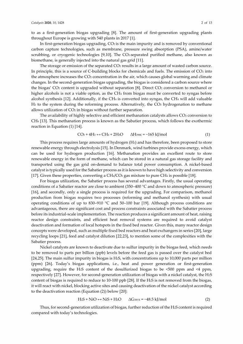
This paper presents the results from thermocatalytic biogas upgradation to methane from the
Methane Gas for Storage of Renewable Energy (MeGa-StoRE) demonstration project. In Figure 1, the
project is schematically presented, where the desulfurization section purifies the raw biogas from the
storage tank before entering the catalytic methanation, upgrading CO2 using H2. In this case, the H2
is produced by water electrolysis to produce biomethane, which is directly fed into the natural gas
grid.
Figure 1. Schematic presentation of the MeGa-StoRE project, including the methanation container and
Green Hydrogen container.
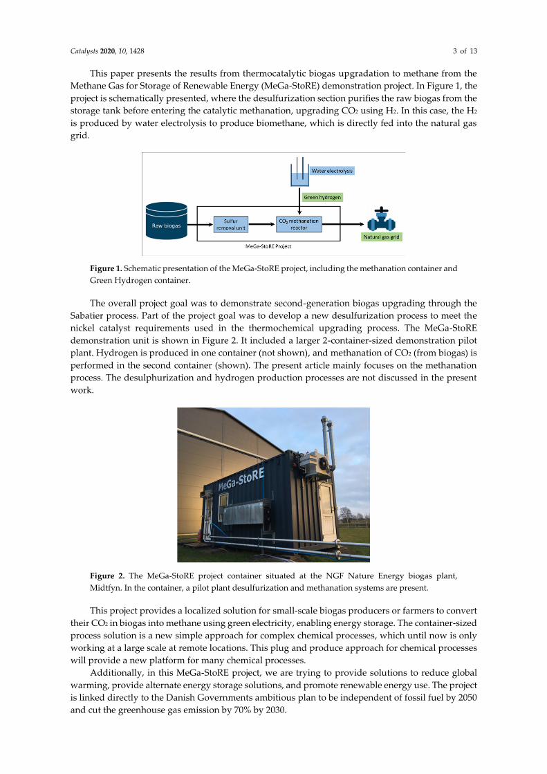
The overall project goal was to demonstrate second-generation biogas upgrading through the
Sabatier process. Part of the project goal was to develop a new desulfurization process to meet the
nickel catalyst requirements used in the thermochemical upgrading process. The MeGa-StoRE
demonstration unit is shown in Figure 2. It included a larger 2-container-sized demonstration pilot
plant. Hydrogen is produced in one container (not shown), and methanation of CO2 (from biogas) is
performed in the second container (shown). The present article mainly focuses on the methanation
process. The desulphurization and hydrogen production processes are not discussed in the present
work.
Figure 2. The MeGa-StoRE project container situated at the NGF Nature Energy biogas plant,
Midtfyn. In the container, a pilot plant desulfurization and methanation systems are present.
This project provides a localized solution for small-scale biogas producers or farmers to convert
their CO2 in biogas into methane using green electricity, enabling energy storage. The container-sized
process solution is a new simple approach for complex chemical processes, which until now is only
working at a large scale at remote locations. This plug and produce approach for chemical processes
will provide a new platform for many chemical processes.
Additionally, in this MeGa-StoRE project, we are trying to provide solutions to reduce global
warming, provide alternate energy storage solutions, and promote renewable energy use. The project
is linked directly to the Danish Governments ambitious plan to be independent of fossil fuel by 2050
and cut the greenhouse gas emission by 70% by 2030.
Catalysts 2020, 10, 1428 4 of 13
2. Results and Discussion
2.1. Thermodynamic Calculations
CO2 methanation reaction is exothermic in nature, where 4 moles of H2 reacts with one mole of
CO2 to form one mole of CH4 and 2 moles of H2O as shown in the main reaction (Equation (1)).
Additionally, this main reaction is also followed by an exothermic reversed water gas shift
(RWGS) reaction and endothermic CO methanation, as shown in Equations (3) and (4), respectively.
H2 + CO2 ↔ CO + H2O ∆H298 K = 41 kJ/mol. (3)
CO + 3H2 ↔ CH4 + H2O ∆H298 K = −206 kJ/mol (4)
The overall CO2 methanation reaction (Equation (1)) is associated with a decrease in the overall
number of gas molecules and releasing heat. Hence, according to Le Chatelier’s principle, the CO2
methanation process should favor high pressure and low process temperature for high methane yield
[29]. Thermodynamic equilibrium calculations were performed using Aspen Hysys V11 by the Gibbs
free energy minimization method to identify the reaction conditions with maximum CO2 conversion
and methane selectivity. Figure 3 shows the effect of temperature and pressure versus CO2
conversion.
(a) (b)
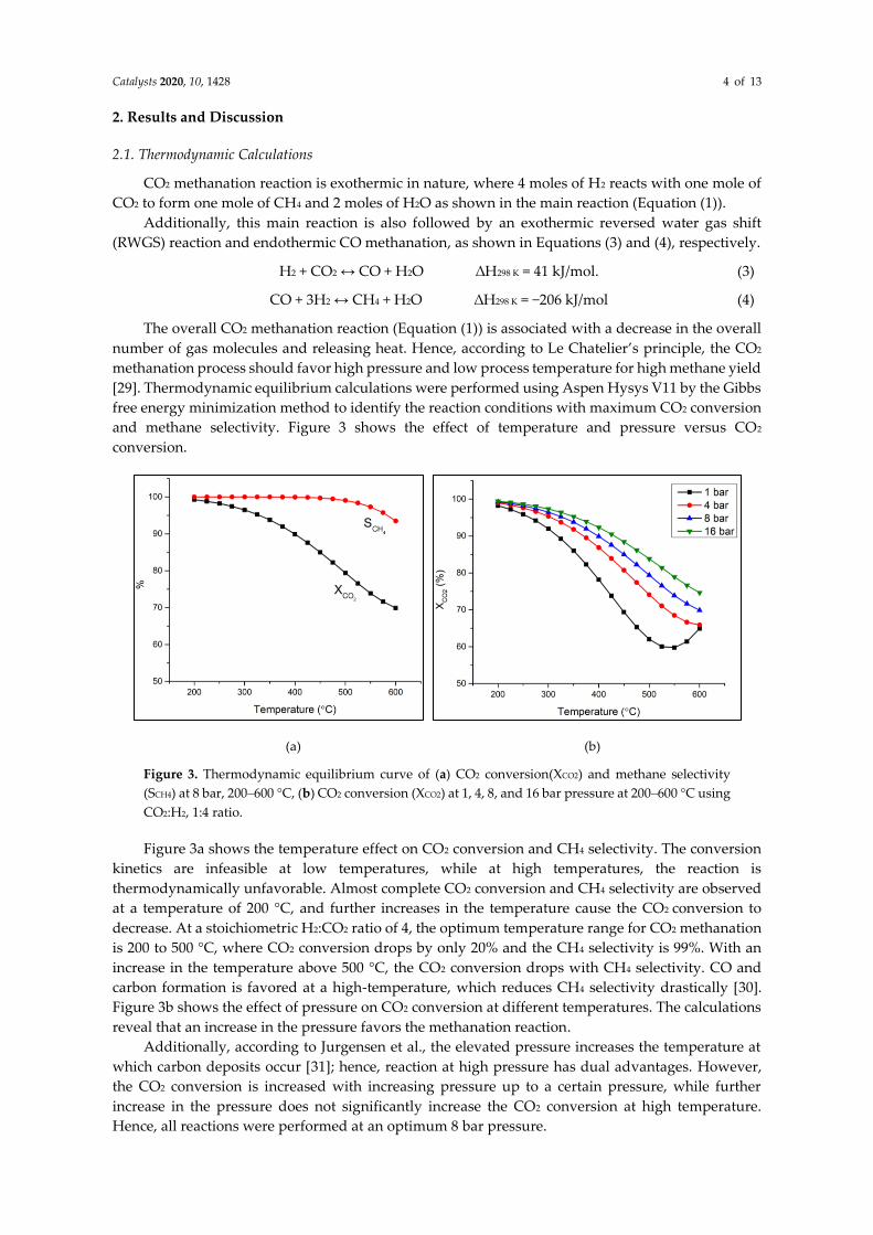
Figure 3. Thermodynamic equilibrium curve of (a) CO2 conversion(XCO2) and methane selectivity
(SCH4) at 8 bar, 200–600 °C, (b) CO2 conversion (XCO2) at 1, 4, 8, and 16 bar pressure at 200–600 °C using
CO2:H2, 1:4 ratio.
Figure 3a shows the temperature effect on CO2 conversion and CH4 selectivity. The conversion
kinetics are infeasible at low temperatures, while at high temperatures, the reaction is
thermodynamically unfavorable. Almost complete CO2 conversion and CH4 selectivity are observed
at a temperature of 200 °C, and further increases in the temperature cause the CO2 conversion to
decrease. At a stoichiometric H2:CO2 ratio of 4, the optimum temperature range for CO2 methanation
is 200 to 500 °C, where CO2 conversion drops by only 20% and the CH4 selectivity is 99%. With an
increase in the temperature above 500 °C, the CO2 conversion drops with CH4 selectivity. CO and
carbon formation is favored at a high-temperature, which reduces CH4 selectivity drastically [30].
Figure 3b shows the effect of pressure on CO2 conversion at different temperatures. The calculations
reveal that an increase in the pressure favors the methanation reaction.
Additionally, according to Jurgensen et al., the elevated pressure increases the temperature at
which carbon deposits occur [31]; hence, reaction at high pressure has dual advantages. However,
the CO2 conversion is increased with increasing pressure up to a certain pressure, while further
increase in the pressure does not significantly increase the CO2 conversion at high temperature.
Hence, all reactions were performed at an optimum 8 bar pressure.
Catalysts 2020, 10, 1428 5 of 13
Reactor design plays an important role in exothermic CO2 methanation, especially using
adiabatic reactors. The benefits of adiabatic reactors are that they are relatively simple in construction
and maintenance, but it is not easy to manage the heat generated [32]. There is a risk of CO and/or
carbon formation in case of too high reactor temperature. CO can be just a byproduct, but the catalyst
surface’s carbon formation may completely deactivate the catalyst over time. Hence reaction heat
management is of utmost importance to avoid carbon formation and catalytic deactivation.
Generally, the heat is either managed by a specially tailored design reactor system, efficient cooling
fluid surrounding the reactor, or diluting the feed gas with an inert gas to lower the heat generation
per volume. Our state-of-the-art reactor design managed the heat generation per volume by adding
total reactant feed in small portions at the inlet of all four reactors and circulating efficient cooling
oil. This process resulted in stable temperature management within the optimal temperature range
(<500 °C), and we achieved almost equilibrium conversion as expected by the above simulations (see
also the discussion in Section 3).
Table 1. shows the expected temperature of the adiabatic reactor system, which was calculated
by Aspen Hysys. The actual reactor temperature recorded by a thermocouple placed in the middle
of the reactor showed that the reactor temperature was within the optimum range.
Table 1. Expected and actual reactor temperature.
Reactors R1 R2 R3 R4
Expected temperature (°C) 471 488 421 348
Actual reactor temperature (°C) 485 485 475 358
2.2. Experimental Results
The pilot plant methanation system ran for approximately 6 months of operation hours,
including the startup and shut down by varying reaction conditions to establish stable operating
conditions. The methanation process ran continuously for 6 h at optimized reaction conditions using
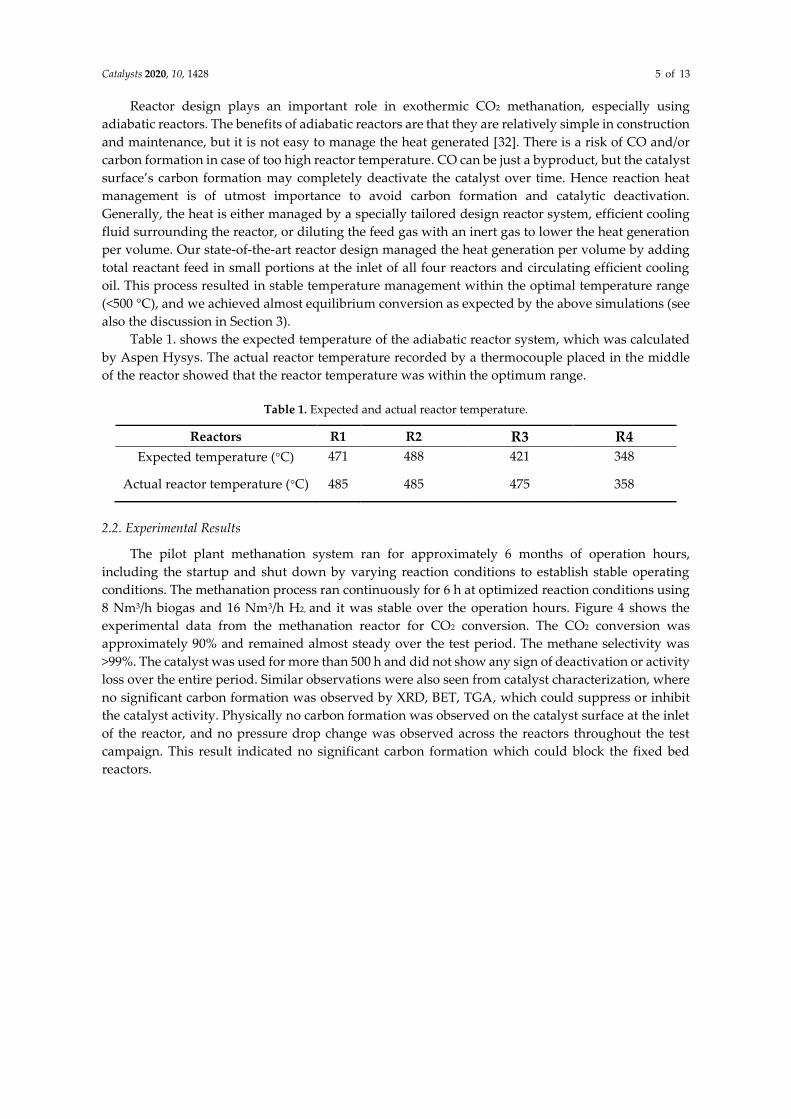
8 Nm3/h biogas and 16 Nm3/h H2, and it was stable over the operation hours. Figure 4 shows the
experimental data from the methanation reactor for CO2 conversion. The CO2 conversion was
approximately 90% and remained almost steady over the test period. The methane selectivity was
>99%. The catalyst was used for more than 500 h and did not show any sign of deactivation or activity
loss over the entire period. Similar observations were also seen from catalyst characterization, where
no significant carbon formation was observed by XRD, BET, TGA, which could suppress or inhibit
the catalyst activity. Physically no carbon formation was observed on the catalyst surface at the inlet
of the reactor, and no pressure drop change was observed across the reactors throughout the test
campaign. This result indicated no significant carbon formation which could block the fixed bed
reactors.
Catalysts 2020, 10, 1428 6 of 13
Figure 4. CO2 conversion from raw, cleaned biogas at 350–500 °C, 8 bar using CH4:CO2:H2 =
23.1:15.4:61.5.
2.3. Catalyst Characterization
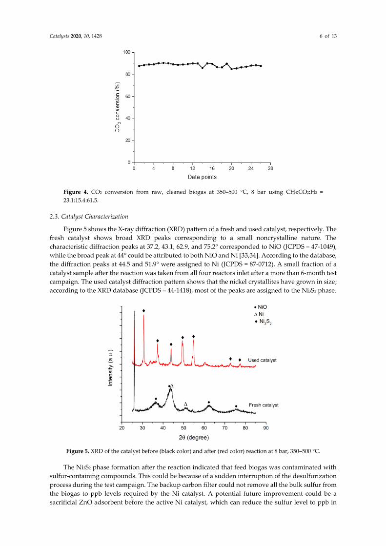
Figure 5 shows the X-ray diffraction (XRD) pattern of a fresh and used catalyst, respectively. The
fresh catalyst shows broad XRD peaks corresponding to a small noncrystalline nature. The
characteristic diffraction peaks at 37.2, 43.1, 62.9, and 75.2° corresponded to NiO (JCPDS = 47-1049),
while the broad peak at 44° could be attributed to both NiO and Ni [33,34]. According to the database,
the diffraction peaks at 44.5 and 51.9° were assigned to Ni (JCPDS = 87-0712). A small fraction of a
catalyst sample after the reaction was taken from all four reactors inlet after a more than 6-month test
campaign. The used catalyst diffraction pattern shows that the nickel crystallites have grown in size;
according to the XRD database (JCPDS = 44-1418), most of the peaks are assigned to the Ni3S2 phase.
Figure 5. XRD of the catalyst before (black color) and after (red color) reaction at 8 bar, 350–500 °C.
The Ni3S2 phase formation after the reaction indicated that feed biogas was contaminated with
sulfur-containing compounds. This could be because of a sudden interruption of the desulfurization
process during the test campaign. The backup carbon filter could not remove all the bulk sulfur from
the biogas to ppb levels required by the Ni catalyst. A potential future improvement could be a
sacrificial ZnO adsorbent before the active Ni catalyst, which can reduce the sulfur level to ppb in
Catalysts 2020, 10, 1428 7 of 13
case of such unforeseen conditions [35,36]. Still, it was surprising to see that the catalyst was active
and showing more than 90% CO2 conversion at all the time. This could be because the catalyst had
better sulfur tolerance capability, or there was a possibility that only the top layer of the catalyst was
poisoned as it was first to expose to biogas. Moreover, later, part of the catalyst was still active, which
provides an active surface for the methanation reaction. According to Hepola et al., sulfur’s catalyst
poisoning decreased along the catalyst bed [37]. Furthermore, before the reactor’s daily startup,
hydrogen treatment might have reactivated some of the nickel sites [38]. A complete mechanistic
study of sulfur poisoning was not a part of this pilot plant test campaign. The diffraction peak at 26.2°
in both diffraction patterns are from the graphite base (JCPDS = 75-2078) used to support the catalyst
sample for XRD analysis.
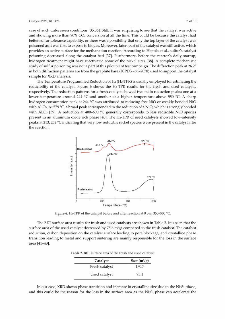
The Temperature Programmed Reduction of H2 (H2-TPR) is usually employed for estimating the
reducibility of the catalyst. Figure 6 shows the H2-TPR results for the fresh and used catalysts,
respectively. The reduction patterns for a fresh catalyst showed two main reduction peaks; one at a
lower temperature around 244 °C and another at a higher temperature above 550 °C. A sharp
hydrogen consumption peak at 244 °C was attributed to reducing free NiO or weakly bonded NiO
with Al2O3. At 579 °C, a broad peak corresponded to the reduction of a NiO, which is strongly bonded
with Al2O3 [39]. A reduction at 400–600 °C generally corresponds to less reducible NiO species
present in an aluminum oxide rich phase [40]. The H2-TPR of used catalysts showed low-intensity
peaks at 213, 252 °C indicating that very low reducible nickel species were present in the catalyst after
the reaction.
Figure 6. H2-TPR of the catalyst before and after reaction at 8 bar, 350−500 °C.
The BET surface area results for fresh and used catalysts are shown in Table 2. It is seen that the
surface area of the used catalyst decreased by 75.6 m2/g compared to the fresh catalyst. The catalyst
reduction, carbon deposition on the catalyst surface leading to pore blockage, and crystalline phase
transition leading to metal and support sintering are mainly responsible for the loss in the surface
area [41–43].
Table 2. BET surface area of the fresh and used catalyst.
Catalyst SBET (m2/g)
Fresh catalyst 170.7
Used catalyst 95.1
In our case, XRD shows phase transition and increase in crystalline size due to the Ni3S2 phase,
and this could be the reason for the loss in the surface area as the Ni3S2 phase can accelerate the
Catalysts 2020, 10, 1428 8 of 13
particle sintering and loss of surface area [44–46]. However, no significant catalytic activity loss was
observed during the catalytic reaction, which shows that carbon species blocked no active species.
Further detailed studies are needed to clarify this catalyst phase formation and its relationship with
catalytic activity.
It is reported that the carbon deposition starts from the formation of graphitic carbon (150–250
°C) and amorphous carbon (250–500 °C) islands on the catalyst surface. The carbon species may
encapsulate the active nickel sites, causing the catalyst’s deactivation, or the carbon may form
filamentous carbon on the catalyst surface. The latter does not encapsulate active sites and will only
reduce the catalytic activity [47]. Since we did not observe drastic changes in the catalytic activity
over a 6-month test campaign, the latter type of carbon formations may very likely occur and thus be
responsible for the loss in the overall surface area along with sulfur poisoning.
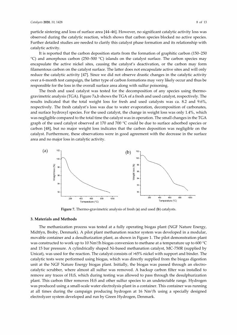
The fresh and used catalyst was tested for the decomposition of any species using thermo-
gravimetric analysis (TGA). Figure 7a,b shows the TGA of a fresh and used catalyst, respectively. The
results indicated that the total weight loss for fresh and used catalysts was ca. 8.2 and 9.6%,
respectively. The fresh catalyst’s loss was due to water evaporation, decomposition of carbonates,
and surface hydroxyl species. For the used catalyst, the change in weight loss was only 1.4%, which
was negligible compared to the total time the catalyst was in operation. The small changes in the TGA
graph of the used catalyst observed at 170 and 700 °C could be due to surface adsorbed species or
carbon [48], but no major weight loss indicates that the carbon deposition was negligible on the
catalyst. Furthermore, these observations were in good agreement with the decrease in the surface
area and no major loss in catalytic activity.
Figure 7. Thermo-gravimetric analysis of fresh (a) and used (b) catalysts.
3. Materials and Methods
The methanization process was tested at a fully operating biogas plant (NGF Nature Energy,
Midtfyn, Broby, Denmark). A pilot plant methanation reactor system was developed in a modular,
movable container and a desulfurization plant, as shown in Figure 1. The pilot demonstration plant
was constructed to work up to 10 Nm3/h biogas conversion to methane at a temperature up to 600 °C
and 15 bar pressure. A cylindrically shaped Ni-based methanation catalyst, MC-750R (supplied by
Unicat), was used for the reaction. The catalyst consists of >65% nickel with support and binder. The
catalytic tests were performed using biogas, which was directly supplied from the biogas digestion
unit at the NGF Nature Energy biogas plant. Initially, the biogas was passed through an electro-
catalytic scrubber, where almost all sulfur was removed. A backup carbon filter was installed to
remove any traces of H2S, which during testing was allowed to pass through the desulphurization
plant. This carbon filter removes H2S and other sulfur species to an undetectable range. Hydrogen
was produced using a small-scale water electrolysis plant in a container. This container was running
at all times during the campaign producing hydrogen at 16 Nm3/h using a specially designed
electrolyzer system developed and run by Green Hydrogen, Denmark.
Catalysts 2020, 10, 1428 9 of 13
3.1. Methanation Reactor
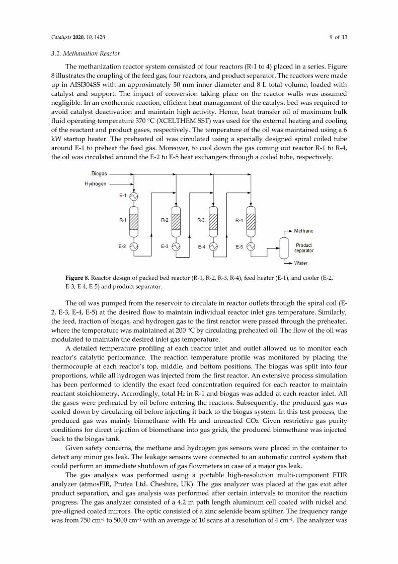
The methanization reactor system consisted of four reactors (R-1 to 4) placed in a series. Figure
8 illustrates the coupling of the feed gas, four reactors, and product separator. The reactors were made
up in AISI304SS with an approximately 50 mm inner diameter and 8 L total volume, loaded with
catalyst and support. The impact of conversion taking place on the reactor walls was assumed
negligible. In an exothermic reaction, efficient heat management of the catalyst bed was required to
avoid catalyst deactivation and maintain high activity. Hence, heat transfer oil of maximum bulk
fluid operating temperature 370 °C (XCELTHEM SST) was used for the external heating and cooling
of the reactant and product gases, respectively. The temperature of the oil was maintained using a 6
kW startup heater. The preheated oil was circulated using a specially designed spiral coiled tube
around E-1 to preheat the feed gas. Moreover, to cool down the gas coming out reactor R-1 to R-4,
the oil was circulated around the E-2 to E-5 heat exchangers through a coiled tube, respectively.
Figure 8. Reactor design of packed bed reactor (R-1, R-2, R-3, R-4), feed heater (E-1), and cooler (E-2,
E-3, E-4, E-5) and product separator.
The oil was pumped from the reservoir to circulate in reactor outlets through the spiral coil (E-
2, E-3, E-4, E-5) at the desired flow to maintain individual reactor inlet gas temperature. Similarly,
the feed, fraction of biogas, and hydrogen gas to the first reactor were passed through the preheater,
where the temperature was maintained at 200 °C by circulating preheated oil. The flow of the oil was
modulated to maintain the desired inlet gas temperature.
A detailed temperature profiling at each reactor inlet and outlet allowed us to monitor each
reactor’s catalytic performance. The reaction temperature profile was monitored by placing the
thermocouple at each reactor’s top, middle, and bottom positions. The biogas was split into four
proportions, while all hydrogen was injected from the first reactor. An extensive process simulation
has been performed to identify the exact feed concentration required for each reactor to maintain
reactant stoichiometry. Accordingly, total H2 in R-1 and biogas was added at each reactor inlet. All
the gases were preheated by oil before entering the reactors. Subsequently, the produced gas was
cooled down by circulating oil before injecting it back to the biogas system. In this test process, the
produced gas was mainly biomethane with H2 and unreacted CO2. Given restrictive gas purity
conditions for direct injection of biomethane into gas grids, the produced biomethane was injected
back to the biogas tank.
Given safety concerns, the methane and hydrogen gas sensors were placed in the container to
detect any minor gas leak. The leakage sensors were connected to an automatic control system that
could perform an immediate shutdown of gas flowmeters in case of a major gas leak.
The gas analysis was performed using a portable high-resolution multi-component FTIR
analyzer (atmosFIR, Protea Ltd. Cheshire, UK). The gas analyzer was placed at the gas exit after
product separation, and gas analysis was performed after certain intervals to monitor the reaction
progress. The gas analyzer consisted of a 4.2 m path length aluminum cell coated with nickel and
pre-aligned coated mirrors. The optic consisted of a zinc selenide beam splitter. The frequency range
was from 750 cm−1 to 5000 cm−1 with an average of 10 scans at a resolution of 4 cm−1. The analyzer was
Catalysts 2020, 10, 1428 10 of 13
calibrated at 60 °C for biogas containing CH4, CO2, and H2S up to 70%, 50%, and 5000 ppm,
respectively.
3.2. Operational Procedure
The complete reactor setup was heat- and pressure-tested before placing the container at the
biogas plant site. The modular container containing both the desulfurization and methanation reactor
system was connected to the biogas storage tank after commissioning. Hydrogen production
container was connected to the methanation reactor system.
As the CO2 methanation reaction is exothermic in nature, the excess heat was removed to avoid
hotspots or overheating the catalyst bed and form carbon species on the catalyst surface.
Additionally, the feed gases were carefully set to avoid cooling down the catalytic beds. Hence, the
operating conditions were initially varied to find optimal reaction conditions for the continuous
startup of all four reactors. To do this, the hydrogen feed flow rate and oil circulation to preheat the
reactant gases were varied. Overall, the CO2 to H2 gas ratio was kept constant at all the time.
However, the biogas flow at each reactor inlet was changed to avoid the fixed bed reactor’s cooling.
The reactor pressure was kept around 8 bar at all the time. At the end of the test, the system was put
into a “sleeping state” until the next day, i.e., the biogas feed flow was stopped, and the reactor was
set to 200 °C under H2 flow until the next operation day.
3.3. Catalytic Tests
The catalyst was reduced in situ before the reaction at 300 °C and 0.5 bar pressure under a 50
mL/min hydrogen set flow. After catalyst reduction, the gas stream was switched to biogas and
hydrogen feed. Typically, the feed gas composition was 38.5% biogas (60% CH4, 40% CO2) and 61.5%
hydrogen. The preheated gas at 200 °C was fed to the reactor; the catalyst bed temperature was varied
from 300 to 550 °C. The produced gas exiting the pilot plant was analyzed immediately. Condensed
water was drained and separated before the produced final gas was injected back to the biogas plant.
The catalytic test ran for 6-8 h of continuous operation.
3.4. Catalyst Characterization
The catalyst was characterized by XRD, BET surface area, and H2 chemisorption before and after
the reaction. After the reaction, catalyst samples were collected from the reactor inlet after the test
campaign. The crystalline phases of fresh and after XRD determined reaction catalysts to identify
phase change or loss in active phase due to long-time heat treatment and reaction. The XRD was
performed using a Bruker D8 X-ray powder diffractometer (Karlsruhe, Germany) with Cu radiation
in a parallel beam geometry. The XRD patterns were recorded with 2θ ranged from 25° to 85°.
N2 adsorption-desorption isotherms determined the BET analysis of the catalysts to find out
whether there was any loss in the active surface area or pore blockage after the reaction. The BET
analysis was performed using a micromeritics ASAP 2460 apparatus (Norcross, GA, USA). The
samples were outgassed at 350 °C for 6 h before being subjected to N2 adsorption to ensure the data’s
accuracy
The reducibility of the catalyst sample was determined by H2-TPR. The measurements were
carried out on a Micromeritics Autochem-II instrument (Norcross, GA, USA) with a reducing mixture
of 5% H2 in N2 from 25 °C to 600 °C with a heating rate of 10 °C/min.
Methanation reaction on nickel catalyst generally forms carbon species on the catalyst surface.
Hence, TGA (NETZSCH STA 449C, Selb, Germany) was performed on fresh and used catalysts to
measure the carbon deposition after the catalytic tests. For accuracy, the used catalyst was ground to
a powder before the measurement. After that, about 160 mg sample was loaded in a crucible, and the
sample was heated to 950 °C at a ramping rate of 4 °C/min under argon flow (flow rate: 20 mL/min).
Catalysts 2020, 10, 1428 11 of 13
4. Conclusions
Direct methanation of CO2 from an operating biogas plant was tested with varying reaction
conditions. A four-stage fixed bed reactor system was developed to achieve maximum biomethane
yield. The temperature profile shows that the reactor temperature could be maintained within the
optimum range (<500 °C) according to simulation calculations. A stable operation of a few hours with
almost 8 Nm3/h biogas feed showed more than 90% CO2 conversion with a small concentration of H2
and CO in the upgraded biogas. The quality of the produced gas was enough to inject into the gas
grid. However, an unrestrictive biomethane injection into the gas grid at the test site needs further
cleaning by removing H2, CO, and unreacted CO2, which could easily be achieved by a gas separator
system. The catalyst stability under harsh reaction conditions was supported by catalyst
characterization after the reactions. Interestingly, Ni phase transformation to Ni2S3 was observed after
reaction with loss in surface area, which needs further investigation using in-situ or operando
characterization techniques. The catalyst does not show deactivation or loss in activity within the
tested period and no major carbon deposits.
In summary, the demonstration of direct CO2 methanation of real biogas using H2 produced by
water electrolysis was implemented successfully. The newly developed desulfurization unit worked
well with almost complete sulfur removal and without any chemical waste production. A successful
long-time stability test with 8 Nm3/h biogas feed showed a Technical Readiness Level of 7. This result
is an important and crucial step towards upscaling and industrial implementation of (desulfurization,
H2 production, and CO2 methanation) state-of-the-art technology at the commercial level.
Author Contributions: P.M., L.P.N. conceptualization, funding acquisition; G.G. designed and build the pilot
demonstration plant, J.P.R., G.G. methodology and designed the experiments; R.G. analyzed the experimental
data, characterized the material, and performed thermodynamic calculations; F.B.G. catalyst characterization;
R.G., S.N.B.V., P.L.F. prepared and wrote the original draft; R.G., P.M., L.P.N., G.G., F.B.G., P.L.F. involved in
review and final editing. All authors have read and agreed to the published version of the manuscript.
Funding: This research was partially funded by the Danish funding program ForskEl, through the MeGa-StoRE
project (journal number 12393).
Acknowledgments: The authors would like to thank the ForskEl program and project partners, DTU MEK,
Elplatek A/S, Unicat Engineering and NGF Nature Energy for financial support. Furthermore, the authors
acknowledged the personnel support at the NGF Nature Energy, Midtfyn Biogas Plant during pilot plant testing.
Conflicts of Interest: The authors declare no conflict of interest.
References
1. European Biogas Association. Annual Report 2018; European Biogas Association: Brussels, Belgium, 2018.
2. Stern, J. The Future of Gas in Decarbonising European Energy Markets: The Need for a New Approach; The Oxford
Institute for Energy Studies: Oxford, UK, 2017.
3. Scarlat, N.; Dallemand, J.-F.; Fahl, F. Biogas: Developments and perspectives in Europe. Renew. Energy 2018,
129, 457–472, doi:10.1016/j.renene.2018.03.006.
4. Strauch, S.; Krassowski, J.; Singhal, A. Biomethane Guide for Decision Makers—Policy Guide on Biogas Injection
into the Natural Gas Grid; Green Gas Grids; Deutsche Energie-Agentur (DENA): Berlin, Germany, 2013.
5. Rasi, S.; Veijanen, A.; Rintala, J. Trace compounds of biogas from different biogas production plants. Energy
2007, 32, 1375–1380, doi:10.1016/j.energy.2006.10.018.
6. Walsh, J.L.; Ross, C.C.; Smith, M.S.; Harper, S.R. Utilization of biogas. Biomass 1989, 20, 277–290,
doi:10.1016/0144-4565(89)90067-X.
7. Ryckebosch, E.; Drouillon, M.; Vervaeren, H. Techniques for transformation of biogas to biomethane.
Biomass Bioenergy 2011, 35, 1633–1645, doi:10.1016/j.biombioe.2011.02.033.
8. Villadsen, S.N.B.; Fosbøl, P.L.; Angelidaki, I.; Woodley, J.M.; Nielsen, L.P.; Møller, P. The Potential of
Biogas; the Solution to Energy Storage. ChemSusChem 2019, 12, 2147–2153, doi:10.1002/cssc.201900100.
9. IEA Bioenergy Task 37. IEA Bioenergy Task 37—Country Reports Summary 2017, 2018; IEA Bioenergy: Paris,
France, 2018.
Catalysts 2020, 10, 1428 12 of 13
10. Yousef, A.M.; El-Maghlany, W.M.; Eldrainy, Y.A.; Attia, A. Upgrading biogas to biomethane and liquid
CO2: A novel cryogenic process. Fuel 2019, 251, 611–628, doi:10.1016/j.fuel.2019.03.127.
11. Friege, C.; Herbes, C. Some Basic Concepts for Marketing Renewable Energy. In Marketing Renewable
Energy; Springer International Publishing: Cham, Switzerland, 2017; doi:10.1007/978-3-319-46427-5_1.
12. Olah, G.A.; Goeppert, A.; Czaun, M.; Prakash, G.K.S. Bi-reforming of Methane from Any Source with Steam
and Carbon Dioxide Exclusively to Metgas (CO–2H2) for Methanol and Hydrocarbon Synthesis. J. Am.
Chem. Soc. 2013, 135, 648–650, doi:10.1021/ja311796n.
13. Witte, J.; Calbry-Muzyka, A.; Wieseler, T.; Hottinger, P.; Biollaz, S.M.A.; Schildhauer, T.J. Demonstrating
direct methanation of real biogas in a fluidised bed reactor. Appl. Energy 2019, 240, 359–371,
doi:10.1016/j.apenergy.2019.01.230.
14. Brooks, K.P.; Hu, J.; Zhu, H.; Kee, R.J. Methanation of carbon dioxide by hydrogen reduction using the
Sabatier process in microchannel reactors. Chem. Eng. Sci. 2007, 62, 1161–1170, doi:10.1016/j.ces.2006.11.020.
15. Castellani, B.; Gambelli, A.M.; Morini, E.; Nastasi, B.; Presciutti, A.; Filipponi, M.; Nicolini, A.; Rossi, F.
Experimental Investigation on CO2 Methanation Process for Solar Energy Storage Compared to CO2-Based
Methanol Synthesis. Energies 2017, 10, 855.
16. Plechinger, M. Energy Watch. Available online: https://energywatch.eu/EnergyNews/Renewables/article
12532617.ece (accessed on 2 December 2020).
17. Martínez, J.; Hernández, E.; Alfaro, S.; López Medina, R.; Valverde Aguilar, G.; Albiter, E.; Valenzuela,
M.A. High Selectivity and Stability of Nickel Catalysts for CO2 Methanation: Support Effects. Catalysts 2019,
9, 24.
18. Abelló, S.; Berrueco, C.; Montané, D. High-loaded nickel–alumina catalyst for direct CO2 hydrogenation
into synthetic natural gas (SNG). Fuel 2013, 113, 598–609, doi:10.1016/j.fuel.2013.06.012.
19. Olah, G.A.; Goeppert, A.; Czaun, M.; Mathew, T.; May, R.B.; Prakash, G.K.S. Single Step Bi-Reforming and
Oxidative Bi-Reforming of Methane (Natural Gas) with Steam and Carbon Dioxide to Metgas (CO-2H2) for
Methanol Synthesis: Self-Sufficient Effective and Exclusive Oxygenation of Methane to Methanol with
Oxygen. J. Am. Chem. Soc. 2015, 137, 8720–8729, doi:10.1021/jacs.5b02029.
20. El Sibai, A.; Rihko Struckmann, L.K.; Sundmacher, K. Model-Based Optimal Sabatier Reactor Design for
Power-to-Gas Applications. Energy Technol. 2017, 5, 911–921, doi:10.1002/ente.201600600.
21. Rönsch, S.; Schneider, J.; Matthischke, S.; Schlüter, M.; Götz, M.; Lefebvre, J.; Prabhakaran, P.; Bajohr, S. Review
on methanation—From fundamentals to current projects. Fuel 2016, 166, 276–296, doi:10.1016/j.fuel.2015.10.111.
22. Matthischke, S. Unsteady-state methanation of carbon dioxide in a fixed-bed recycle reactor—Experimental
results for transient flow rate ramps. Fuel Process. Technol. 2016, 153, 87–93, doi:10.1016/j.fuproc.2016.07.021.
23. Fache, A.; Marias, F.; Guerré, V.; Palmade, S. Optimization of fixed-bed methanation reactors: Safe and
efficient operation under transient and steady-state conditions. Chem. Eng. Sci. 2018, 192, 1124–1137,
doi:10.1016/j.ces.2018.08.044.
24. Bartholomew, C.H. Mechanisms of catalyst deactivation. Appl. Catal. A Gen. 2001, 212, 17–60,
doi:10.1016/S0926-860X(00)00843-7.
25. Abatzoglou, N.; Boivin, S. A review of biogas purification processes. Biofuels Bioprod. Biorefin. 2009, 3, 42–
71, doi:10.1002/bbb.117.
26. Persson, M.; Jönsson, O.; Wellinger, A. Biogas Upgrading to Vehicle Fuel Standards and Grid Injection Biogas;
Upgrading I; IEA Bioenergy: Paris, France, 2006.
27. Allegue, L.B.; Hinge, J. Biogas Upgrading Evaluation of Methods for H2S Removal; Danish Technological
Institute: Taastrup, Denmark, 2014; pp. 1–31.
28. Rabou, L.P.L.M.; Bos, L. High efficiency production of substitute natural gas from biomass. Appl. Catal. B
Environ. 2012, 111–112, 456–460, doi:10.1016/j.apcatb.2011.10.034.
29. Gao, J.; Wang, Y.; Ping, Y.; Hu, D.; Xu, G.; Gu, F.; Su, F. A thermodynamic analysis of methanation reactions
of carbon oxides for the production of synthetic natural gas. RSC Adv. 2012, 2, 2358–2368,
doi:10.1039/C2RA00632D.
30. Stangeland, K.; Kalai, D.; Li, H.; Yu, Z. CO2 Methanation: The Effect of Catalysts and Reaction Conditions.
Energy Procedia 2017, 105, 2022–2027, doi:10.1016/j.egypro.2017.03.577.
31. Jürgensen, L.; Ehimen, E.A.; Born, J.; Holm-Nielsen, J.B. Dynamic biogas upgrading based on the Sabatier
process: Thermodynamic and dynamic process simulation. Bioresour. Technol. 2015, 178, 323–329,
doi:10.1016/j.biortech.2014.10.069.
Catalysts 2020, 10, 1428 13 of 13
32. Jekaterina, P.; Gatis, B.; Darja, M. Modeling of the Adiabatic and Isothermal Methanation Process. Environ.
Clim. Technol. 2011, 6, 79–84, doi:10.2478/v10145-011-0011-5.
33. Moon, D.H.; Lee, S.M.; Ahn, J.Y.; Nguyen, D.D.; Kim, S.S.; Chang, S.W. New Ni-based quaternary disk-
shaped catalysts for low-temperature CO2 methanation: Fabrication, characterization, and performance. J.
Environ. Manag. 2018, 218, 88–94, doi:10.1016/j.jenvman.2018.04.034.
34. Wu, H.; Yin, K.; Qi, W.; Zhou, X.; He, J.; Li, J.; Liu, Y.; He, J.; Gong, S.; Li, Y. Rapid Fabrication of
Ni/NiO@CoFe Layered Double Hydroxide Hierarchical Nanostructures by Femtosecond Laser Ablation
and Electrodeposition for Efficient Overall Water Splitting. ChemSusChem 2019, 12, 2773–2779,
doi:10.1002/cssc.201900479.
35. Dannesboe, C.; Hansen, J.B.; Johannsen, I. Removal of sulfur contaminants from biogas to enable direct
catalytic methanation. Biomass Convers. Biorefin. 2019, doi:10.1007/s13399-019-00570-7.
36. Frilund, C.; Simell, P.; Kaisalo, N.; Kurkela, E.; Koskinen-Soivi, M.-L. Desulfurization of Biomass Syngas
Using ZnO-Based Adsorbents: Long-Term Hydrogen Sulfide Breakthrough Experiments. Energy Fuels
2020, 34, 3316–3325, doi:10.1021/acs.energyfuels.9b04276.
37. Hepola, J.; Simell, P.; Kurkela, E.; Ståhlberg, P. Sulphur poisoning of nickel catalysts in catalytic hot gas
cleaning conditions of biomass gasification. In Studies in Surface Science and Catalysis; Delmon, B., Froment,
G.F., Eds.; Elsevier: Amsterdam, The Netherlands, 1994; Volume 88, pp. 499–506.
38. Gac, W.; Zawadzki, W.; Rotko, M.; Słowik, G.; Greluk, M. CO2 Methanation in the Presence of Ce-Promoted
Alumina Supported Nickel Catalysts: H2S Deactivation Studies. Top. Catal. 2019, 62, 524–534,
doi:10.1007/s11244-019-01148-3.
39. Khzouz, M.; Gkanas, E.I. Experimental and Numerical Study of Low Temperature Methane Steam
Reforming for Hydrogen Production. Catalysts 2017, 8, 5.
40. He, Z.; Wang, X.; Liu, R.; Gao, S.; Xiao, T. Perfomances of different additives on NiO/γ-Al2O3 catalyst in CO
methanation. Appl. Petrochem. Res. 2016, 6, 235–241, doi:10.1007/s13203-016-0160-3.
41. Gao, Y.; Meng, F.; Ji, K.; Song, Y.; Li, Z. Slurry phase methanation of carbon monoxide over nanosized Ni–
Al2O3 catalysts prepared by microwave-assisted solution combustion. Appl. Catal. A Gen. 2016, 510, 74–83,
doi:10.1016/j.apcata.2015.11.006.
42. Zhu, L.; Yin, S.; Wang, X.; Liu, Y.; Wang, S. The catalytic properties evolution of HZSM-5 in the conversion
of methanol to gasoline. RSC Adv. 2016, 6, 82515–82522, doi:10.1039/C6RA16373D.
43. Li, P.; Park, Y.H.; Moon, D.J.; Park, N.C.; Kim, Y.C. Carbon Deposition Onto Ni-Based Catalysts for Combined
Steam/CO2 Reforming of Methane. J. Nanosci. Nanotechnol. 2016, 16, 1562–1566, doi:10.1166/jnn.2016.12006.
44. Dou, X.; Veksha, A.; Chan, W.P.; Oh, W.-D.; Liang, Y.N.; Teoh, F.; Mohamed, D.K.B.; Giannis, A.; Lisak, G.;
Lim, T.-T. Poisoning effects of H2S and HCl on the naphthalene steam reforming and water-gas shift
activities of Ni and Fe catalysts. Fuel 2019, 241, 1008–1018, doi:10.1016/j.fuel.2018.12.119.
45. Méndez-Mateos, D.; Barrio, V.L.; Requies, J.M.; Cambra, J.F. A study of deactivation by H2S and
regeneration of a Ni catalyst supported on Al2O3, during methanation of CO2. Effect of the promoters Co,
Cr, Fe and Mo. RSC Adv. 2020, 10, 16551–16564, doi:10.1039/D0RA00882F.
46. Albertazzi, S.; Basile, F.; Brandin, J.; Einvall, J.; Fornasari, G.; Hulteberg, C.; Sanati, M.; Trifirò, F.; Vaccari,
A. Effect of fly ash and H2S on a Ni-based catalyst for the upgrading of a biomass-generated gas. Biomass
Bioenergy 2008, 32, 345–353, doi:10.1016/j.biombioe.2007.10.002.
47. Luisetto, I.; Tuti, S.; Battocchio, C.; Lo Mastro, S.; Sodo, A. Ni/CeO2–Al2O3 catalysts for the dry reforming
of methane: The effect of CeAlO3 content and nickel crystallite size on catalytic activity and coke resistance.
Appl. Catal. A Gen. 2015, 500, 12–22, doi:10.1016/j.apcata.2015.05.004.
48. Awad, A.; Salam, A.; Abdullah, B. Thermocatalytic decomposition of methane/methanol mixture for
hydrogen production: Effect of nickel loadings on alumina support. AIP Conf. Proc. 2017, 1891, 020030,
doi:10.1063/1.5005363.
Publisher’s Note: MDPI stays neutral with regard to jurisdictional claims in published maps and institutional
affiliations.
© 2020 by the authors. Licensee MDPI, Basel, Switzerland. This article is an open access
article distributed under the terms and conditions of the Creative Commons Attribution
(CC BY) license (http://creativecommons.org/licenses/by/4.0/).