Construction Specification Engineering SpecificationEngineering Specification Signals Construction...
101
Engineering Specification Signals Construction Specification Engineering Specification SPG 1240 SIGNALLING ELECTRONIC SYSTEM VERIFICATION Version 1.1 Issued May 2010 Owner: Warwick Allison, Chief Engineer Signals and Control Systems Approved by: Warwick Allison Chief Engineer Signals and Control Systems Authorised by: Paul Szacsvay Principal Engineer Signal Technology Disclaimer This document was prepared for use on the RailCorp Network only. RailCorp makes no warranties, express or implied, that compliance with the contents of this document shall be sufficient to ensure safe systems or work or operation. It is the document user’s sole responsibility to ensure that the copy of the document it is viewing is the current version of the document as in use by RailCorp. RailCorp accepts no liability whatsoever in relation to the use of this document by any party, and RailCorp excludes any liability which arises in any manner by the use of this document. Copyright The information in this document is protected by Copyright and no part of this document may be reproduced, altered, stored or transmitted by any person without the prior consent of RailCorp. UNCONTROLLED WHEN PRINTED Page 1 of 101
Transcript of Construction Specification Engineering SpecificationEngineering Specification Signals Construction...

Engineering Specification Signals Construction Specification
Engi
neer
ing
Spec
ifica
tion
SPG 1240
SIGNALLING ELECTRONIC SYSTEM VERIFICATION
Version 1.1
Issued May 2010
Owner: Warwick Allison, Chief Engineer Signals and Control Systems
Approved by:
Warwick Allison Chief Engineer Signals and Control Systems
Authorised by:
Paul Szacsvay Principal Engineer Signal Technology
Disclaimer This document was prepared for use on the RailCorp Network only. RailCorp makes no warranties, express or implied, that compliance with the contents of this document shall be sufficient to ensure safe systems or work or operation. It is the document user’s sole responsibility to ensure that the copy of the document it is viewing is the current version of the document as in use by RailCorp. RailCorp accepts no liability whatsoever in relation to the use of this document by any party, and RailCorp excludes any liability which arises in any manner by the use of this document. Copyright The information in this document is protected by Copyright and no part of this document may be reproduced, altered, stored or transmitted by any person without the prior consent of RailCorp.
UNCONTROLLED WHEN PRINTED Page 1 of 101

RailCorp Engineering Specification — Signals — Construction Specification Signalling Electronic System Verification SPG 1240
© RailCorp Page 2 of 101 Issued May 2010 UNCONTROLLED WHEN PRINTED Version 1.1
Document control
Version Date Summary of change
1.0 20/08/2007 Replaced SC 00 21 01 00 SP Signalling Electronic System Verification v.2.0 of 1 November 2001RailCorp format
1.1 May 2010 Application of TMA 400 format.

RailCorp Engineering Specification — Signals — Construction Specification Signalling Electronic System Verification SPG 1240
© RailCorp Page 3 of 101 Issued May 2010 UNCONTROLLED WHEN PRINTED Version 1.1
Contents
1 Test Plan Identifier ..................................................................................................................6 2 Introduction .............................................................................................................................6
2.1 Objectives ..................................................................................................................6 2.2 Background................................................................................................................6 2.3 Scope.........................................................................................................................6 2.4 References ................................................................................................................7
3 Test Items ................................................................................................................................7 4 Features to be Tested.............................................................................................................7 5 Features not to be tested .......................................................................................................9 6 Approach .................................................................................................................................9
6.1 Functionality...............................................................................................................9 6.2 Interface testing .......................................................................................................10 6.3 Regression testing ...................................................................................................10 6.4 Comprehensiveness ................................................................................................10 6.5 Constraints...............................................................................................................10 6.6 Test-Incident Reports ..............................................................................................10
7 Item pass/fail criteria ............................................................................................................10 8 Suspension criteria and resumption requirements...........................................................11
8.1 Suspension Criteria .................................................................................................11 8.2 Resumption Requirements ......................................................................................11
9 Test deliverables ...................................................................................................................11 10 Testing tasks .........................................................................................................................11 11 Environmental needs............................................................................................................12
11.1 Hardware .................................................................................................................12 11.2 Software...................................................................................................................12 11.3 Security ....................................................................................................................12 11.4 Tools ........................................................................................................................12 11.5 Documentation.........................................................................................................12
12 Responsibilities.....................................................................................................................12 12.1 Testers.....................................................................................................................13 12.2 Supplier....................................................................................................................13 12.3 Configuration Manager ............................................................................................13 12.4 RailCorp’s Representative.......................................................................................13
13 Staffing and training needs..................................................................................................13 13.1 Staffing.....................................................................................................................13 13.2 Training....................................................................................................................14
14 Schedule ................................................................................................................................15 15 Risks and Contingencies .....................................................................................................15
15.1 Hardware problems .................................................................................................15 15.2 Software problems...................................................................................................15 15.3 Resourcing problems...............................................................................................15

RailCorp Engineering Specification — Signals — Construction Specification Signalling Electronic System Verification SPG 1240
© RailCorp Page 4 of 101 Issued May 2010 UNCONTROLLED WHEN PRINTED Version 1.1
15.4 Access for testing ....................................................................................................15 15.5 Unresolved Incidents ...............................................................................................16 15.6 Insufficient testing and stress testing of the system................................................16 15.7 Disruption to Rail operations ...................................................................................16 15.8 Occupational Health and Safety ..............................................................................16 15.9 Safe Working Units ..................................................................................................16
Appendix A Example Test Log Format.....................................................................................17 Appendix B Incident Report Form ............................................................................................18 Appendix C Test Design Specifications...................................................................................19
Test Design Specification TD-001 - Fitness for Purpose........................................................20 Test Design Specification TD-002 - Memory check on start-up .............................................21 Test Design Specification TD-003 - Logging ..........................................................................22 Test Design Specification TD-004 - System status display ....................................................24 Test Design Specification TD-005 - Indications......................................................................25 Test Design Specification TD-006 - Spare Capacity ..............................................................26 Test Design Specification TD-007 - Response times .............................................................27 Test Design Specification TD-008 - Reliability........................................................................28 Test Design Specification TD-009 - Life .................................................................................30 Test Design Specification TD-010 - Recovery times ..............................................................31 Test Design Specification TD-011 - Automatic Start-up and Re-start ....................................32 Test Design Specification TD-012 - Display symbols .............................................................33 Test Design Specification TD-013 - Data Entry ......................................................................34 Test Design Specification TD-014 - Service Degradation ......................................................35 Test Design Specification TD-015 - Provision for Safeworking Procedures...........................36 Test Design Specification TD-016 - Documentation...............................................................37 Test Design Specification TD-017 - Training ..........................................................................38 Test Design Specification TD-018 - Spares............................................................................39 Test Design Specification TD-019 - Type approval ................................................................40 Test Design Specification TD-020 - General Physical Aspects ..............................................41 Test Design Specification TD-021 - Surge protection.............................................................43 Test Design Specification TD-022 - Durability ........................................................................44 Test Design Specification TD-023 - Electromagnetic Compatibility .......................................45 Test Design Specification TD-024 - Sound Levels .................................................................46 Test Design Specification TD-025 - Fire Hazard ....................................................................47 Test Design Specification TD-026 - Labelling.........................................................................48 Test Design Specification TD-027 - Power Supply interface ..................................................49 Test Design Specification TD-028 - Communications interface .............................................51 Test Design Specification TD-029 - Signalling interface.........................................................54 Test Design Specification TD-030 - User/Operator interface .................................................55 Test Design Specification TD-031 - Other Interfaces .............................................................56 Test Design Specification TD-032 - Integrity ..........................................................................57 Test Design Specification TD-033 - Occupational Health and Safety ....................................59 Test Design Specification TD-034 - Maintenance aspects .....................................................60 Test Design Specification TD-035 - Diagnostics ....................................................................61 Test Design Specification TD-036 - Deliverables ...................................................................62
RailCorp Engineering Specification — Signals — Construction Specification Signalling Electronic System Verification SPG 1240
© RailCorp Page 5 of 101 Issued May 2010 UNCONTROLLED WHEN PRINTED Version 1.1
Test Design Specification TD-037 - System Confidence test .................................................63 Test Design Specification TD-038 – Signalling Operator Interface ........................................64 Test Design Specification TD-039 – Train Control System ....................................................65
Appendix D Test Case Specifications ......................................................................................67 Test Case Specification TC003LBT - Logger boundary testing..............................................68 Test Case Specification TC003LCF - Configuration of log. ....................................................69 Test Case Specification TC003LGR Logger review. ..............................................................70 Test Case Specification - TC003LGT Logger timing .............................................................71 Test Case Specification - TC003LRA Remote access of log. ................................................72 Test Case Specification - TC003LTD review of a 3 day period of the actual log. ..................73 Test Case Specification 004SS - TC 004SS System health indication and
procedures for determining the cause of a reduced health state. ...........................74 Test Case Specification - TC 005CIC Control Indication correspondence test. .....................75 Test Case Specification TC 005ICT Indication correspondence test. ....................................76 Test Case Specification - TC 005IND Review of indications. ................................................77 Test Case Specification TC 005REP Review of reports.........................................................78 Test Case Specification - TC 007CCT Command completion time........................................79 Test Case Specification - TC 007CIT Control indication time.................................................80 Test Case Specification - TC 007CRT Control response time. ..............................................81 Test Case Specification - TC 007IRT Indication response time .............................................82 Test Case Specification - TC 007UDR Update dynamic report time......................................83 Test Case Specification - TC 027INT Immunity of the system from loss of power
supply of less than 0.25 seconds. ...........................................................................84 Test Case Specification - TC 028DIS Recovery from disruptions. .........................................86 Test Case Specification - TC 028ERR Communications error rate........................................87 Test Case Specification - TC 028MDL Multi-drop links. .........................................................88 Test Case Specification - TC 028MOD Modem approvals. ....................................................89 Test Case Specification - TC 028MON Monitor points ...........................................................90 Test Case Specification - TC 028PRO Design of communications protocols for
error detection and ensuring no loss if information or sequence. ...........................91 Test Case Specification - TC 030CHG No loss of information or alarms during
change of users and or operators............................................................................93 Test Case Specification - TC 030LOG “log on” / “log off” procedure to take less
than 1 minute. ..........................................................................................................94 Test Case Specification - TC 031INT Other Interface design and approval
check........................................................................................................................95 Test Case Specification - TC 032CTL Likelihood for issuing spurious controls. ....................96 Test Case Specification - TC 032EVL Logic Evaluation.........................................................97 Test Case Specification - TC 032INT Integrity of facilities......................................................99 Test Case Specification - TC 032PRT Protected against unauthorised access.................. 100 Test Case Specification - TC 032RSK Level of risk for the proposed usage of
the system. ........................................................................................................... 101

RailCorp Engineering Specification — Signals — Construction Specification Signalling Electronic System Verification SPG 1240
© RailCorp Page 6 of 101 Issued May 2010 UNCONTROLLED WHEN PRINTED Version 1.1
1 Test Plan Identifier RailCorp Specification SPG 1240 Signalling Electronic System Verification is to be used for verification of compliance with Standard Requirements for Signalling Electronic Systems and related specifications.
This document is a generic Test Plan for the testing of Signalling Electronic Systems in accordance with Australian Standard Software test documentation AS 4006 – 1992. A Test Plan may be tailored for a specific system, however any reduction in the extent or scope of testing implied by this document may only be undertaken after a waiver is granted by RailCorp’s Representative.
2 Introduction
2.1 Objectives This system test plan is a generic test plan designed to provide objective evidence that each system being provided to RailCorp complies with its specifications, and is fit for purpose.
Testing is to be completed before the system is commissioned or brought into operational use.
All systems provided in accordance with RailCorp Specification SPG 1240 Standard Requirements for Signalling Electronic Systems are to be tested in accordance with this generic test plan or a specific test plan based on this generic test plan.
Those parts of systems provided in accordance with RailCorp Specification SPG 0719 Computer Based Interlocking Requirements that are not directly safety related are to be tested in accordance with this generic test plan or a specific test plan based on this generic test plan.
2.2 Background The initial performance of Signalling Electronic Systems provided to RailCorp have been poor in terms of reliability and operability. This test plan is a response to ‘teething’ problems with Signalling Electronic Systems, to prevent the bringing into use of systems that can not be demonstrated to have an acceptable level of performance.
2.3 Scope This test plan covers the full set of system tests, some of which may only be required during or as part of the ‘type approval’ process for new or modified products. Those features that are only tested as part of ‘type approval’ are identified as such.
This is a generic test plan designed to cover a large range of system types, system configurations, sizes of system, and criticality. Signalling Electronic Systems can be categorised as being one of the following types:
a) Logging System
b) Monitoring System
c) Information System
d) Signalling Control System

RailCorp Engineering Specification — Signals — Construction Specification Signalling Electronic System Verification SPG 1240
© RailCorp Page 7 of 101 Issued May 2010 UNCONTROLLED WHEN PRINTED Version 1.1
e) Telemetry System
f) Train Control System
Each of these system types shall be tested in accordance with this test plan although some tests may not be applicable to the particular system being tested. RailCorp’s Representative will decide the applicability of tests if there is any doubt about the test’s applicability.
The tests are designed to cover the complete lifecycle of the system.
2.4 References The following RailCorp Signalling Specifications are used as sources of information for the test plan.
Standard Requirements for Signalling Electronic Systems SPG 1240. Signaller Operator Interface ESG 0004. Inspection and Testing of New and Altered Signalling Works SPG 0711. Computer Based Interlocking Requirements SPG 0719. Specification - General Requirements for Labelling of Equipment SPG 1031. Lightning and Surge Protection Requirements SPG 0712. Specification – Connectors for Signalling Interface SPG 1030. Specification – Solderless Terminals – Cable Lugs for Signalling Applications SPG 1066.
3 Test Items All items that make up the system shall be tested during the system tests, including: Software, Firmware, Hardware, Interfaces, User procedures, and Maintenance procedures.
The system hardware, software, and documentation are to be tested ‘as built’ or in the state that is proposed for delivery. Tests should be carried out during the development to ensure that the ‘as built’ system will pass the required tests.
Prior to the commencement of the system tests, the system must be under configuration management, with any changes being made under configuration control.
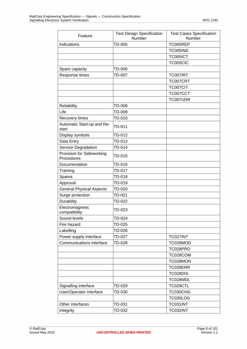
4 Features to be Tested The following table details the features to be tested.
Feature Test Design Specification Number
Test Cases Specification Number
Fitness for Purpose TD-001 Memory check on start-up TD-002 Logging TD-003 TC003LGT TC003LRA TC003LCF TC003LBT TC003LTD TC003LGR System status display TD-004 TC004SS
RailCorp Engineering Specification — Signals — Construction Specification Signalling Electronic System Verification SPG 1240
© RailCorp Page 8 of 101 Issued May 2010 UNCONTROLLED WHEN PRINTED Version 1.1
Test Cases Specification Number Feature Test Design Specification
Number Indications TD-005 TC005REP TC005IND TC005ICT TC005CIC Spare capacity TD-006 Response times TD-007 TC007IRT TC007CRT TC007CIT TC007CCT TC007UDR Reliability TD-008 Life TD-009 Recovery times TD-010 Automatic Start-up and Re-start TD-011
Display symbols TD-012 Data Entry TD-013 Service Degradation TD-014 Provision for Safeworking Procedures TD-015
Documentation TD-016 Training TD-017 Spares TD-018 Approval TD-019 General Physical Aspects TD-020 Surge protection TD-021 Durability TD-022 Electromagnetic compatibility TD-023
Sound levels TD-024 Fire hazard TD-025 Labelling TD-026 Power supply interface TD-027 TC027INT Communications interface TD-028 TC028MOD TC028PRO TC028COM TC028MON TC028ERR TC028DIS TC028MDL Signalling interface TD-029 TC029CTL User/Operator interface TD-030 TC030CHG TC030LOG Other interfaces TD-031 TC031INT Integrity TD-032 TC032INT

RailCorp Engineering Specification — Signals — Construction Specification Signalling Electronic System Verification SPG 1240
© RailCorp Page 9 of 101 Issued May 2010 UNCONTROLLED WHEN PRINTED Version 1.1
Test Cases Specification Number Feature Test Design Specification
Number TC032IND TC032EVL TC032CTL TC032RSK TC032PRT Occupational Health and Safety TD-033
Maintenance aspects TD-034 Diagnostics TD-035 Deliverables TD-036 System Confidence Test TD-037 Signalling Operator Interface TD-038
Train Control System TD-039
5 Features not to be tested All features of the system are intended to be tested, either by demonstration, inspection or analysis. If the Supplier wishes to claim a waiver to the requirement to test a particular feature then the Supplier must lodge a request for waiver with RailCorp’s Representative. The claim for a waiver should detail where and how the feature has been previously tested.
6 Approach Testing will normally be completed in the following stages:
a) Goods Receiving tests
b) Type Approval tests
c) Factory Acceptance Tests (FAT)
d) Site Acceptance Tests (SAT)
e) Commissioning Tests
Formal Reviews may also be scheduled at any stage during development and testing.
The larger and more complex the systems is, then the more extensive the testing shall be.
Tests are considered to be one of three classes, Demonstration, Inspection, or Analysis. Each feature is expected to have at least one Demonstration test, and one Inspection test.
6.1 Functionality All functionality will be tested in each mode of operation. The tests will include a set of extreme cases, conditions at the limits of operation, and possible misuse of the system.

RailCorp Engineering Specification — Signals — Construction Specification Signalling Electronic System Verification SPG 1240
© RailCorp Page 10 of 101 Issued May 2010 UNCONTROLLED WHEN PRINTED Version 1.1
6.2 Interface testing All interfaces shall be tested. Interfaces shall be tested in both directions, that is outward from the system and inward to the system. Any tests that cover an interface will be designed to overlap tests that would be done when approaching the interface from the other side.
6.3 Regression testing It is acknowledged that there may be multiple versions of some modules or data during the testing of the system.
Prior to the introduction of a new version of a module or data to the test configuration, the differences between the new version and the previous version are to be documented.
The differences between the versions are analysed and a set of tests selected to re-test those features that may have been affected and have already been tested. If there is not complete confidence and agreement that a feature is unaffected then it is to be re-tested.
As part of the introduction of a new version into the test configuration the System Confidence Tests shall be run in addition to the tests selected to re-test the affected features.
6.4 Comprehensiveness Each system feature, facility, and performance criteria shall be formally tested for an number of normal situations, and extreme conditions.
6.5 Constraints Features that are identified as being uneconomic to test or requiring too much time to test may be sample tested, or tested by analysis or inspection provided that a reasonable justification can be presented and a test waiver granted by RailCorp’s Representative.
6.6 Test-Incident Reports An incident report shall be created each time an unexpected event or error occurs during testing. An index of all test incident reports shall be maintained in a computer database or spreadsheet and include a status field.
7 Item pass/fail criteria The system must pass all of the test design specifications for it to be accepted as suitable for commissioning.
All incident reports should have had the corrective action determined, implemented, and passed the required re-testing. There may be outstanding incident reports but these must have had the corrective action determined and scheduled, and have been accepted by RailCorp’s Representative. Acceptance of passing a test subject to outstanding incident reports may only be done by RailCorp’s Representative on the grounds that the outstanding incident is minor, and does not require significant re-testing, and has no foreseeable impact on future testing or operational use.
Incidents that occur during a test and cannot be reproduced must be considered as a serious problem with the system because these incidents are normally an indicator that significant problems will occur during operational use. No Fault Found Incidents must undergo a formal review conducted by RailCorp’s Representatives.

RailCorp Engineering Specification — Signals — Construction Specification Signalling Electronic System Verification SPG 1240
© RailCorp Page 11 of 101 Issued May 2010 UNCONTROLLED WHEN PRINTED Version 1.1
The review may then accept the incident, as no further action required.
8 Suspension criteria and resumption requirements
8.1 Suspension Criteria Testing must be suspended if a fault with the system has been identified that prevents testing, or may require the features that have not been tested to be re-tested during regression testing. Either RailCorp’s Representative or the Supplier's Representative may suspend testing at any time that they have reasons to believe that the testing may no longer be valid.
8.2 Resumption Requirements RailCorp’s Representative and the Supplier's Representative must agree that the test arrangements are valid, then testing will resume after regression testing as described in section 6.3 has been completed, without the suspension criteria occurring.
9 Test deliverables The following documents shall be generated by the tester and the configuration manager, and provided to the Project Manager for inclusion in the commissioning records:
a) Test Documentation
b) Test Data
c) Test Log
d) Test Waivers
e) Configuration records
f) Incident reports, including details on corrective action.
g) Signed test certificates
10 Testing tasks Testers are those personnel responsible for conducting the testing and may be employed by the Supplier, RailCorp’s Representative, or RailCorp.
The testers shall:
a) Prepare all system specific test plans
b) Prepare all system specific test design specifications.
c) Prepare all system specific test case specifications.
d) Prepare all system specific test procedure specifications.
e) Create all required test data
f) Resource the testing process.
g) Perform tests in accordance with test plans.

RailCorp Engineering Specification — Signals — Construction Specification Signalling Electronic System Verification SPG 1240
© RailCorp Page 12 of 101 Issued May 2010 UNCONTROLLED WHEN PRINTED Version 1.1
h) Produce a Test Log that provides a chronological record of relevant details about the execution of the tests. The format of the Test Log will be as per Appendix A
i) Analyse test results
j) Resolve incident reports in conjunction with the Supplier and RailCorp’s Representative.
k) Write, and sign a test report.
l) Produce any required test certificates.
The Supplier shall supply and maintain the test configurations to meet the requirements of the tests.
11 Environmental needs
11.1 Hardware The test environment should have the system hardware installed and configured in as close the to final configuration as is possible. There will typically be a number of test configurations. Firstly for the Type Approval Tests or specific item tests, secondly for the Factory Acceptance Tests, and thirdly for the Site Acceptance Tests. Each of these test configurations will allow for the system internal and external interfaces to be tested. As the system moves to each next phase of testing, more of the interfaces will become internal to the system under test.
11.2 Software The test environment should have the system software and data installed and configured in as close to the final configuration as is possible. The software under test will be stimulated by separate test software as necessary. Less test software will be used as the system moves to each next phase of testing.
11.3 Security The test setup will be secured against any unauthorised, or unintended changes.
11.4 Tools The test environment must have an appropriate set of tools to perform the testing and for identification of faults. The tools must include both hardware and software diagnostic and test tools.
11.5 Documentation The test environment should have a set of ‘as built’ documentation of the system hardware, software, and data as installed and configured for the test configuration.
12 Responsibilities The following parties have responsibilities in the testing of the system.

RailCorp Engineering Specification — Signals — Construction Specification Signalling Electronic System Verification SPG 1240
© RailCorp Page 13 of 101 Issued May 2010 UNCONTROLLED WHEN PRINTED Version 1.1
12.1 Testers The testers are responsible for:
a) Creating any specific test documentation
b) performing each test,
c) recording any incidents,
d) collection of test data,
e) recording results,
f) producing a test log,
g) signing off any test certificates.
12.2 Supplier The Supplier is responsible for:
a) Setting up and maintaining the test configurations.
b) Managing, resourcing, conducting, and documenting all testing.
c) Responding to incident reports.
d) Testing up to and across all external system interfaces.
12.3 Configuration Manager The configuration manager is responsible for identifying the system configuration and managing changes to the system configuration.
12.4 RailCorp’s Representative RailCorp’s Representative is responsible for:
a) Confirming that the testing is carried out in a thorough and professional manner.
b) Obtaining and providing access to the system for test if the system is in use or the tests may affect Rail operations, or impact on Rail Safety.
c) Providing witnesses to testing where required.
d) Conducting any technical reviews.
13 Staffing and training needs
13.1 Staffing The provision of adequate, qualified staff is the responsibility of both the Supplier and RailCorp’s Representative.
The testing staff should be independent from the staff involved in the development of the item or feature being tested. At least one independent person shall be involved in any formal test.

RailCorp Engineering Specification — Signals — Construction Specification Signalling Electronic System Verification SPG 1240
© RailCorp Page 14 of 101 Issued May 2010 UNCONTROLLED WHEN PRINTED Version 1.1
13.2 Training Prior to any formal tests the staff performing the tests must be assessed and certified as competent to perform the tests and detect any anomalies that may occur while the tester is preparing for the tests, during the tests, or as part of the wrap up after the tests.
Training shall be provided to the testers so that they are competent to perform their testing duties.

RailCorp Engineering Specification — Signals — Construction Specification Signalling Electronic System Verification SPG 1240
14 Schedule The testers will create a schedule for the testing of the particular system.
The schedule will include time for incident rectification, regression testing and re-testing.
A typical schedule would be as follows:
Test Time Goods Receiving tests
© RailCorp Page 15 of 101 Issued May 2010 UNCONTROLLED WHEN PRINTED Version 1.1
Type Approval tests
Factory Acceptance Tests (FAT)
Rectification and Retesting
Site Acceptance Tests (SAT)
Rectification and Retesting
Commissioning Tests
15 Risks and Contingencies This section considers the normal risks and their contingencies. The test plan for the particular system must consider and deal with any additional risks for the particular system.
15.1 Hardware problems Spare parts and arrangement for repair and modification of faulty items must be in place prior to commencement of testing
15.2 Software problems Strict software configuration management and backup procedures must be documented and followed from the commencement of testing.
Arrangements must be in place for software modification, data modification, configuration modification, for the duration of testing and for the post commissioning standby period.
15.3 Resourcing problems A source for suitable additional resources must be identified, so that additional resources may be obtained if required during testing and during the post commissioning standby period.
15.4 Access for testing Access to the system for testing is restricted when the tests may affect Rail operations, or impact on Rail Safety. Testing should be scheduled so that tests that require access can

RailCorp Engineering Specification — Signals — Construction Specification Signalling Electronic System Verification SPG 1240
© RailCorp Page 16 of 101 Issued May 2010 UNCONTROLLED WHEN PRINTED Version 1.1
be completed with the minimum duration of access. Preliminary tests must be performed prior to access being granted. The preliminary tests must provide a 90% confidence level that the system is likely to pass any test where access is restricted.
15.5 Unresolved Incidents A suitable resource must be available to devote time to an exhaustive analysis of unresolved incidents so that their possible causes and future impacts can be assessed and the relevant investigations carried out to check the possible causes.
15.6 Insufficient testing and stress testing of the system An independent review of the particular system’s test plans is required to confirm that the testing will include the depth, and breadth of testing as well as stresses to 10% more that expected loading. A 95% confidence level is required at the commencement of the commissioning process that the system will operate as specified at the scheduled completion of commissioning.
15.7 Disruption to Rail operations Careful consideration needs to be given to potential causes of disruption to rail operations during the testing and steps taken to reduce the risk of the disruption occurring due to the testing.
15.8 Occupational Health and Safety Careful consideration needs to be given to potential causes of Occupational Health and Safety problems during the testing and steps taken to minimise the risk of these problems occurring due to the testing.
15.9 Safe Working Units RailCorp’s Safe Working Units must be complied with at all times.

RailCorp Engineering Specification — Signals — Construction Specification Signalling Electronic System Verification SPG 1240
© RailCorp Page 17 of 101 Issued May 2010 UNCONTROLLED WHEN PRINTED Version 1.1
Appendix A Example Test Log Format a) Test Procedure Specification Identifier
A unique identification of the Test Procedure for which the test log is a record.
b) Description
Details of the items tested, including version/revision, where the test items are and the test Case or Test Procedure being run.
c) Activities and Event Entries
Details of who did what, when, and the results of the tests.
d) Configuration details
Exact details of how the system and test were setup and run.
RailCorp Engineering Specification — Signals — Construction Specification Signalling Electronic System Verification SPG 1240
© RailCorp Page 18 of 101 Issued May 2010 UNCONTROLLED WHEN PRINTED Version 1.1
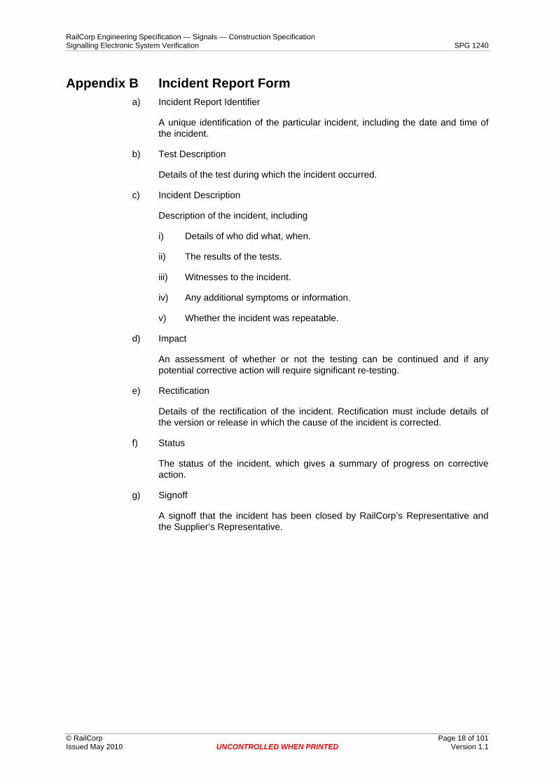
Appendix B Incident Report Form a) Incident Report Identifier
A unique identification of the particular incident, including the date and time of the incident.
b) Test Description
Details of the test during which the incident occurred.
c) Incident Description
Description of the incident, including
i) Details of who did what, when.
ii) The results of the tests.
iii) Witnesses to the incident.
iv) Any additional symptoms or information.
v) Whether the incident was repeatable.
d) Impact
An assessment of whether or not the testing can be continued and if any potential corrective action will require significant re-testing.
e) Rectification
Details of the rectification of the incident. Rectification must include details of the version or release in which the cause of the incident is corrected.
f) Status
The status of the incident, which gives a summary of progress on corrective action.
g) Signoff
A signoff that the incident has been closed by RailCorp’s Representative and the Supplier’s Representative.

RailCorp Engineering Specification — Signals — Construction Specification Signalling Electronic System Verification SPG 1240
© RailCorp Page 19 of 101 Issued May 2010 UNCONTROLLED WHEN PRINTED Version 1.1
Appendix C Test Design Specifications This appendix contains each of the Test Design Specifications. Each Test Design Specification commences on a new page.

RailCorp Engineering Specification — Signals — Construction Specification Signalling Electronic System Verification SPG 1240
© RailCorp Page 20 of 101 Issued May 2010 UNCONTROLLED WHEN PRINTED Version 1.1
Test Design Specification TD-001 - Fitness for Purpose a) Features to be tested
Standard Requirements for Signalling Electronic Systems SPG 1240, Section 4.1 Fitness for Purpose. This includes the examining the major features of the system in the environment the system is intended to be installed, including:
Functionality (Each necessary element of functionality exists.)
Suitability (The system is appropriate for the intended use.)
Safety (The system can meet the safety requirement.)
Reliability (The system can meet the reliability requirement.)
Durability (The system will last for its intended life and with-stand foreseeable misuse, and damage.)
Maintainability (The system can meet the maintainability requirement.)
Operability (Each function can be used as intended, and its intended method of use is valid).
Supportability (The system will able to be modified, and have replacement parts obtained for its intended life.)
b) Approach Refinements
This is carried out as a Technical Review prior to Factory Acceptance Testing with input from:
i) Users.
ii) Maintainers.
iii) Suppliers.
iv) Clients Representative for particular discipline.
v) Clients Representative.
The Technical Review will be in accordance with RailCorp’s Technical Review procedure.
c) Associated Test Cases
No Test Cases are associated with this test. This test will be conducted in accordance with RailCorp’s Technical Review procedure.
d) Feature Pass/Fail Criteria
Consensus from the technical review panel that the system is fit for purpose.

RailCorp Engineering Specification — Signals — Construction Specification Signalling Electronic System Verification SPG 1240
© RailCorp Page 21 of 101 Issued May 2010 UNCONTROLLED WHEN PRINTED Version 1.1
Test Design Specification TD-002 - Memory check on start-up a) Features to be tested
Standard Requirements for Signalling Electronic Systems SPG 1240, Section 4.2 Memory check on start-up
b) Approach Refinements
This test is performed during Type Approval or Factory Acceptance Testing.
Firstly identify items that require a memory check. Secondly confirm that each item is configured for memory check on start-up, that the memory check feature is documented, and includes details of what the system does when it detects an error. If the feature is not fully documented then a full demonstration test shall be performed to confirm that the memory check is performed on start-up.
The demonstration test will include with faulty memory, and good memory.
c) Associated Test Cases
There is no generic test case provided for this test design.
d) Feature Pass/Fail Criteria
All processor based modules shall have a documented memory check feature or pass Test Case for the system to pass this test.

RailCorp Engineering Specification — Signals — Construction Specification Signalling Electronic System Verification SPG 1240
© RailCorp Page 22 of 101 Issued May 2010 UNCONTROLLED WHEN PRINTED Version 1.1
Test Design Specification TD-003 - Logging a) Features to be tested
Standard Requirements for Signalling Electronic Systems SPG 1240, Sections:
4.3 Logging
4.4 System status (part)
4.10 Automatic Start-up and Re-start (part)
4.12 Data Entry (part)
4.13 Service Degradation (part)
12. Integrity (part)
14.2 Diagnostic indications (part)
14.3 Diagnostic test facilities and data (part)
Checking the date/time and setting the date/time without disruption to logging.
Computer-Based Interlocking Requirements SPG 0719, Sections:
3.15 Event Recorder
Features marked as part are only examining that feature in regard to logging.
b) Approach Refinements
The above features are to be tested during Factory Acceptance Testing. In addition a review of a three day period of the actual log is to be conducted during Site Acceptance Testing, and again after commissioning.
The operation of the logging facility, the display of and setting the clock, the log file names, obtaining log from live system, the minimum storage and maintenance of the log when power is removed shall be checked by demonstration testing.
The format of the log report shall be reviewed by maintenance staff, the Supplier and RailCorp’s Representative.
The durability and integrity of the log shall be checked by an inspection of the design.
The accuracy of time stamping, the reference clock and detection of events shall be checked by demonstration testing of the system.
The performance and response of the system when the log reaches its limits and during periods of maximum loading shall be checked by demonstration testing.
Remote access facilities shall be tested by demonstration with at least 10 repetitions whilst events are being logged, with at least 5 repetitions for accessing the current log file.
Significant dates and times that could cause the clock or log storage to malfunction shall be identified and the logging checked by demonstration for each of these dates and times.

RailCorp Engineering Specification — Signals — Construction Specification Signalling Electronic System Verification SPG 1240
© RailCorp Page 23 of 101 Issued May 2010 UNCONTROLLED WHEN PRINTED Version 1.1
c) Associated Test Cases
The following Test Cases shall be performed to test these features.
Logger timing TC003LGT
Accuracy of log (to 1 second).
Resolution of log (to 0.2 second).
Accuracy and drift of clock.
Logger usage
Remote access of log. TC003LRA
Configuration of log. TC003LCF
Logger boundary testing TC003LBT
Duration of log.
Stress (maximum loading).
Log size reaching maximum capacity.
Logger review TC003LGR
Durability of log.
Producing log reports.
Readability of log reports.
A 3 day period of the actual log. TC003LTD
d) Feature Pass/Fail Criteria
Each feature must be tested and pass each individual test for the system to pass this test.

RailCorp Engineering Specification — Signals — Construction Specification Signalling Electronic System Verification SPG 1240
© RailCorp Page 24 of 101 Issued May 2010 UNCONTROLLED WHEN PRINTED Version 1.1
Test Design Specification TD-004 - System status display a) Features to be tested
Standard Requirements for Signalling Electronic Systems SPG 1240, Sections:
4.4 System Status.
14.2 Diagnostic indications (part)
5.5 Maintenance Manual
Features marked as part are only examining that feature in regard to System status display.
b) Approach Refinements
These features shall be tested during Factory Acceptance Testing.
The system and all sub-systems are to be identified, then for each sub-system and the system as a whole, all of the health states shall be identified and fully corresponded. The testing shall include a 100% test of each warning condition, a 100% test of each alarm condition, and a 100% test of each failure condition. An extensive range of events that would be expected to occur but not be considered as warning, alarm, or failure conditions shall be tested to confirm that normal conditions or events do not cause warnings or alarms.
All causes of the reduced health indications shall be identified. The procedures for determining the cause of reduced health indications shall be reviewed against the causes identified to confirm the accuracy of the indications.
c) Associated Test Cases
The following Test Cases shall be performed to test these features.
Indication of system and sub-systems health and procedures TC004SS for determining the cause of reduced health states.
d) Feature Pass/Fail Criteria
Each feature must be tested and pass each individual test for the system to pass this test.

RailCorp Engineering Specification — Signals — Construction Specification Signalling Electronic System Verification SPG 1240
© RailCorp Page 25 of 101 Issued May 2010 UNCONTROLLED WHEN PRINTED Version 1.1
Test Design Specification TD-005 - Indications a) Features to be tested
Standard Requirements for Signalling Electronic Systems SPG 1240, Sections:
4.5 Indications
12 Integrity (part)
b) Approach Refinements
These features are to be tested during Factory Acceptance Testing. Re-testing shall be required as part of Site Acceptance Testing and Commissioning to ensure indications are tested across all internal sub-system interfaces and external system interfaces.
The requirements of Signalling Operator Interface ESG 0004 and Signal and Control Systems SPG 0713 shall be considered.
All reports shall be generated. RailCorp’s Representative shall review the presentation of the reports.
All states of each indication type shall be simulated. RailCorp’s Representative will review each state of each indication type against indication principles for consistency and conformance with the principles.
All indications and the indications of controls shall be fully correspondence tested. RailCorp’s Representative shall review the indications of controls against indication principles.
Multiple flashing indications shall be caused to occur and the flashing indications examined for consistent duty cycle and to confirm that flashing indications flash in sync with each other.
During Factory Acceptance Testing:
100% demonstration test of the correspondence of each signalling indication state.
During Site Acceptance Testing:
100% demonstration test of the correspondence of each signalling indication state for the complete system.
c) Associated Test Cases
The following Test Cases shall be performed to test these features.
Review of reports. TC005REP
Review of indications TC005IND
Indication correspondence test TC005ICT
Control Indication correspondence test. TC005CIC
d) Feature Pass/Fail Criteria
Each feature must be tested and pass each individual test for the system to pass this test.

RailCorp Engineering Specification — Signals — Construction Specification Signalling Electronic System Verification SPG 1240
© RailCorp Page 26 of 101 Issued May 2010 UNCONTROLLED WHEN PRINTED Version 1.1
Test Design Specification TD-006 - Spare Capacity a) Features to be tested
Standard Requirements for Signalling Electronic Systems SPG 1240, Sections:
4.6 Spare capacity
b) Approach Refinements
This feature shall be tested by analysis during the Factory Acceptance Test. The analysis shall identify spare capacity in the systems as designed including spare memory, processing time, spare equipment space, installed spare I/O capacity, uninstalled spare I/O capacity etc.
c) Associated Test Cases
There are no associated test cases.
d) Feature Pass/Fail Criteria
The system shall comply with all the requirements for spare capacity to pass this test.

RailCorp Engineering Specification — Signals — Construction Specification Signalling Electronic System Verification SPG 1240
© RailCorp Page 27 of 101 Issued May 2010 UNCONTROLLED WHEN PRINTED Version 1.1
Test Design Specification TD-007 - Response times a) Features to be tested
Standard Requirements for Signalling Electronic Systems SPG 1240, Sections:
4.7 Response times
b) Approach Refinements
This feature is to be tested during Factory Acceptance Testing and again during Site Acceptance Testing.
The response times shall be tested by both analysis and demonstration test.
Time measurements will be made by stopwatch and repeated at least 5 times and averaged. An allowance of up to 0.25 seconds may be made for the response of the person operating the stopwatch. Typically there will be a person at each location to observe input and output states of the system with voice communications between the locations to allow measurement of the response times.
c) Associated Test Cases
The following Test Cases shall be performed to test these features.
Indication response time. TC007IRT
Control response time. TC007CRT
Control indication time. TC007CIT
Command completion time and Report completion time. TC007CCT
Update dynamic report time. TC007UDR
d) Feature Pass/Fail Criteria
Each feature must be tested and pass each individual test for the system to pass this test.

RailCorp Engineering Specification — Signals — Construction Specification Signalling Electronic System Verification SPG 1240
© RailCorp Page 28 of 101 Issued May 2010 UNCONTROLLED WHEN PRINTED Version 1.1
Test Design Specification TD-008 - Reliability a) Features to be tested
Standard Requirements for Signalling Electronic Systems SPG 1240, Sections:
4.8 Reliability and life (part)
Computer-Based Interlocking Requirements SPG 0719, Section:
4.3.7 Reliability and Preventative Maintenance Monitoring
b) Approach Refinements
This feature is to be tested throughout development, testing, and defects liability phase of the project.
As part of the Type Approval process
Reliability analysis including system MTBF calculation for each failure category. The Supplier is responsible for providing the base information for the analysis, and proposed system configuration or typical configuration.
Interface analysis, to confirm that the interfaces are fully compatible.
As part of the Factory Acceptance Tests:
Endurance demonstration tests for a minimum period of 24 hours.
Stress demonstration tests for a minimum of stress of 110% of the rated capacity, designed capacity or the expected maximum usage.
Monitoring system operation during Factory Acceptance Testing, including a record of each time the system is started, stopped, reset and the reason for the action.
As part of the Site Acceptance Tests
Endurance demonstration tests.
Stress demonstration tests.
Monitoring system operation during Site Acceptance Testing including a record of each time the system is started, stopped, reset and the reason for the action.
During the Design, Installation, Testing, and defects liability period
Monitor the system reliability.
Collate and review fault reports.
Provide a Reliability and Maintainability Analysis Report at the completion of each phase of design and testing.
c) Associated Test Cases
There are no associated test cases.
RailCorp Engineering Specification — Signals — Construction Specification Signalling Electronic System Verification SPG 1240
© RailCorp Page 29 of 101 Issued May 2010 UNCONTROLLED WHEN PRINTED Version 1.1
d) Feature Pass/Fail Criteria
The reliability for the system must be within specification, and the results approved by RailCorp’s Representative for the system to pass this test.
The results of the Stress and Endurance tests must also be satisfactory.

RailCorp Engineering Specification — Signals — Construction Specification Signalling Electronic System Verification SPG 1240
© RailCorp Page 30 of 101 Issued May 2010 UNCONTROLLED WHEN PRINTED Version 1.1
Test Design Specification TD-009 - Life a) Features to be tested
Standard Requirements for Signalling Electronic Systems SPG 1240, Sections:
4.8 Reliability and life (part)
b) Approach Refinements
These features are to be tested by analysis as part of the Type Approval Tests.
The analysis shall consider:
The Supplier's evidence that the requirement is met.
Spare parts are attainable throughout the expected life.
The expected life can be met.
Significant events during the expected life of the system and how the system will handle the event. An example would be date functionality in when changing from 31/12/1999 to 1/1/2000.
The results of the analysis shall be presented as a report on the expected life of the system and what will be required to achieve the desired life.
c) Associated Test Cases
There are no associated test cases.
d) Feature Pass/Fail Criteria
The report shall be approved by RailCorp’s Representative for the system to pass this test.

RailCorp Engineering Specification — Signals — Construction Specification Signalling Electronic System Verification SPG 1240
© RailCorp Page 31 of 101 Issued May 2010 UNCONTROLLED WHEN PRINTED Version 1.1
Test Design Specification TD-010 - Recovery times a) Features to be tested
Standard Requirements for Signalling Electronic Systems SPG 1240, Sections:
4.9 Recovery times
Computer-Based Interlocking Requirements SPG 0719, Sections:
4.4.5 Recovery Times
b) Approach Refinements
These features are to be tested during Factory Acceptance Testing.
These tests shall be performed as a demonstration test on a sample basis. One of each type and function of module shall be initialised as a new component and reinstalled in the system. The time the module takes to return to full operational service shall be recorded.
An analysis shall then be conducted on the results. Any modules that exceed the 4 minute recovery time shall require a formal waiver from RailCorp’s Representative.
The recovery times shall be measured, and provided to RailCorp’s Representative with the module descriptions, and module MTBF for review of suitability.
c) Associated Test Cases
There are no associated test cases.
d) Feature Pass/Fail Criteria
Each module must pass this test or be formally granted a waiver by RailCorp’s Representative for the system to pass this test.

RailCorp Engineering Specification — Signals — Construction Specification Signalling Electronic System Verification SPG 1240
© RailCorp Page 32 of 101 Issued May 2010 UNCONTROLLED WHEN PRINTED Version 1.1
Test Design Specification TD-011 - Automatic Start-up and Re-start
a) Features to be tested
Standard Requirements for Signalling Electronic Systems SPG 1240, Sections:
4.10 Automatic Start-up and Re-start
b) Approach Refinements
These features are to be tested during Factory Acceptance Testing.
Identify each individual system/sub-system type and for each type the power shall be interrupted and the system or sub-system observed to determine if it restarts without intervention or assistance.
Any recoverable failure shall be simulated to occur, then the fault cleared and the system or sub-system observed to determine if the system or sub-system restarts without intervention or assistance.
c) Associated Test Cases
There are no associated test cases.
d) Feature Pass/Fail Criteria
Each system or sub-system shall automatically restart where required for the system to pass this test.

RailCorp Engineering Specification — Signals — Construction Specification Signalling Electronic System Verification SPG 1240
© RailCorp Page 33 of 101 Issued May 2010 UNCONTROLLED WHEN PRINTED Version 1.1
Test Design Specification TD-012 - Display symbols a) Features to be tested
Standard Requirements for Signalling Electronic Systems SPG 1240, Sections:
4.11 Display symbols
Lack of ambiguity in display symbols.
b) Approach Refinements
These features are to be tested during Factory Acceptance Testing.
The display symbols need to have the approval of RailCorp’s Representative before this test can commence. The first part of the test is to check the existence and approval of the display symbols
The requirements of Signalling Operator Interface ESG 0004 and Signal and Control Systems SPG 0713 shall be considered.
The display symbols shall be inspected to check conformance to the approved symbols and existing practices. The RailCorp’s Representative is required to witness this test.
A sample demonstration test shall be performed to display each indication state for each symbol type to confirm that the display symbols are un-ambiguous and capable of displaying the full range of indications.
c) Associated Test Cases
There are no associated test cases.
d) Feature Pass/Fail Criteria
All display symbols shall conform to those approved for the system to pass this test.

RailCorp Engineering Specification — Signals — Construction Specification Signalling Electronic System Verification SPG 1240
© RailCorp Page 34 of 101 Issued May 2010 UNCONTROLLED WHEN PRINTED Version 1.1
Test Design Specification TD-013 - Data Entry a) Features to be tested
Standard Requirements for Signalling Electronic Systems SPG 1240, Sections:
4.12 Data Entry
5.9 Data Generation
b) Approach Refinements
These features are to be tested during Factory Acceptance Testing.
The data entry principles need to be defined, and have the approval of the RailCorp’s Representative before this test can commence. The first part of the test is to check the existence and approval of the principles.
All the data that forms part of the system shall be reviewed for conformance to the principles, this test can not be performed by any person directly involved in writing the data.
If the system requires an initial data entry effort of more than one working day for one person then facilities shall be provided to assist in the data entry and maintenance of the data. The RailCorp Representative shall review these facilities.
An independent person shall inspect the data for the system.
c) Associated Test Cases
There are no associated test cases.
d) Feature Pass/Fail Criteria
Each feature must be tested and pass each individual test for the system to pass this test.

RailCorp Engineering Specification — Signals — Construction Specification Signalling Electronic System Verification SPG 1240
© RailCorp Page 35 of 101 Issued May 2010 UNCONTROLLED WHEN PRINTED Version 1.1
Test Design Specification TD-014 - Service Degradation a) Features to be tested
Standard Requirements for Signalling Electronic Systems SPG 1240, Sections:
4.13 Service Degradation.
b) Approach Refinements
These features are to be tested during Factory Acceptance Testing.
The design, especially of communication protocols and message/information passing, shall be reviewed to ensure that no information can be lost without an alarm or warning occurring.
The design shall also be reviewed to ensure that the system has a method of automatically correcting any lost information or data within one minute.
Where the system's response to overload conditions is documented, this feature does not require testing. Otherwise overload conditions shall be simulated in a factory test set up to ensure the system responds appropriately.
c) Associated Test Cases
There are no associated test cases.
d) Feature Pass/Fail Criteria
Each feature must be tested and pass each individual test for the system to pass this test.

RailCorp Engineering Specification — Signals — Construction Specification Signalling Electronic System Verification SPG 1240
© RailCorp Page 36 of 101 Issued May 2010 UNCONTROLLED WHEN PRINTED Version 1.1
Test Design Specification TD-015 - Provision for Safeworking Procedures
a) Features to be tested
Standard Requirements for Signalling Electronic Systems SPG 1240, Sections:
4.14 Provision for Safeworking Procedures
Computer-Based Interlocking Requirements SPG 0719, Sections:
3.14 Vital Blocking Facilities
b) Approach Refinements
These features shall be reviewed for type approval and tested during Factory Acceptance Testing.
The provision and integrity of Safeworking Procedures is to be demonstrated and approved by the RailCorp’s Representative during type approval.
The Supplier shall demonstrate to RailCorp’s Representative that the level of risk is low in all cases.
The method for determining the level of risk shall be in accordance with AS 4360 Risk Management.
A 100% test of each Safeworking procedure/Blocking facility shall be carried out during the Factory Acceptance Testing.
The Safeworking Procedures/Blocking facilities shall be sample tested for a range of equipment and software failure conditions and for a range of Operator errors.
c) Associated Test Cases
There are no associated test cases.
d) Feature Pass/Fail Criteria
The Safeworking Procedures/Blocking facilities shall be approved by RailCorp’s Representative for the system to pass this test.

RailCorp Engineering Specification — Signals — Construction Specification Signalling Electronic System Verification SPG 1240
© RailCorp Page 37 of 101 Issued May 2010 UNCONTROLLED WHEN PRINTED Version 1.1
Test Design Specification TD-016 - Documentation a) Features to be tested
Standard Requirements for Signalling Electronic Systems SPG 1240, Sections:
5.1 Documentation – General.
The documentation shall truly reflect the system, it shall be complete, easy to use, lack ambiguity and be of a professional standard.
b) Approach Refinements
These features are to be tested during Factory Acceptance Testing.
The documentation provided with the system shall be reviewed for:
Accuracy.
Completeness.
Ease of use.
Lack of ambiguity.
Professional standard.
Sufficient to maintain the system for its intended life
Sufficient to train new users, operators, and maintainers.
All procedures shall be tested by an actual demonstration of the procedure, assuming only the knowledge/experience of the person that would normally perform the task. The tester may accept configuration options as per the defaults provided by the original supplier if there are no particular configuration details provided in the procedure.
The documentation shall be actively used during all stages of testing and Incidents recorded against the Documentation test for each problem found with the documentation.
The maintenance procedures for Fault finding, Software installation, Software or data back-up, Software or data restore shall be performed during Factory Acceptance Testing.
Each maintenance action detailed in the Service Schedules of Technical Maintenance Plan for the equipment shall be performed.
Each User or Operator procedure shall be performed in accordance with the documentation to demonstrate the documentation is correct.
c) Associated Test Cases
Each Test Case that uses the system documentation is associated with this test design. The testers shall record any incidents relating to documentation found during testing.
d) Feature Pass/Fail Criteria
All documentation must have the approval of RailCorp’s Representative for the system to pass this test.

RailCorp Engineering Specification — Signals — Construction Specification Signalling Electronic System Verification SPG 1240
© RailCorp Page 38 of 101 Issued May 2010 UNCONTROLLED WHEN PRINTED Version 1.1
Test Design Specification TD-017 - Training a) Features to be tested
Standard Requirements for Signalling Electronic Systems SPG 1240, Sections:
6 Training.
b) Approach Refinements
These features are to be tested during Factory Acceptance Testing.
The course notes and contents shall be reviewed for the following: -
appropriate for the level of competence of the participants.
sufficient to achieve maintenance and reliability requirements.
The course notes and contents shall be submitted to RailCorp’s Representative for approval at least four (4) weeks prior to the training taking place.
c) Associated Test Cases
There are no associated test cases.
d) Feature Pass/Fail Criteria
The course notes and contents must be approved by RailCorp’s Representative for the system to pass this test.

RailCorp Engineering Specification — Signals — Construction Specification Signalling Electronic System Verification SPG 1240
© RailCorp Page 39 of 101 Issued May 2010 UNCONTROLLED WHEN PRINTED Version 1.1
Test Design Specification TD-018 - Spares a) Features to be tested
Standard Requirements for Signalling Electronic Systems SPG 1240, Sections:
7a) Spares.
Computer-Based Interlocking Requirements SPG 0719, Sections:
4.4.8 Spare Parts
b) Approach Refinements
These features are to be tested during Factory Acceptance Testing and Site Acceptance Testing.
The Supplier shall provide adequate evidence to RailCorp’s Representative that the spares being provided with the system are sufficient to allow the system’s specified mean time to repair to be met throughout the life of the system. This spares list and evidence of adequacy shall be checked by RailCorp’s Representative.
During Site Acceptance Testing the spares provided shall be checked against the list of spares specified, the compatibility and configuration of the spares shall be checked against the installed system.
c) Associated Test Cases
There are no associated test cases.
d) Feature Pass/Fail Criteria
Each feature must be tested and pass each individual test for the system to pass this test.

RailCorp Engineering Specification — Signals — Construction Specification Signalling Electronic System Verification SPG 1240
© RailCorp Page 40 of 101 Issued May 2010 UNCONTROLLED WHEN PRINTED Version 1.1
Test Design Specification TD-019 - Type approval a) Features to be tested
Standard Requirements for Signalling Electronic Systems SPG 1240, Sections:
9 Approval.
b) Approach Refinements
This feature is to be tested during Factory Acceptance Testing.
All components and sub-systems shall be checked to confirm that they are type approved for the version and application.
c) Associated Test Cases
There are no associated test cases.
d) Feature Pass/Fail Criteria
Each component and sub-system requiring type approval must be type approved for the intended use for the system to pass this test.

RailCorp Engineering Specification — Signals — Construction Specification Signalling Electronic System Verification SPG 1240
© RailCorp Page 41 of 101 Issued May 2010 UNCONTROLLED WHEN PRINTED Version 1.1
Test Design Specification TD-020 - General Physical Aspects a) Features to be tested
Standard Requirements for Signalling Electronic Systems SPG 1240, Sections:
10.1 Physical Aspects - General.
All installation work shall be of a high standard.
All wiring shall be neat with sufficient but not excessive slack.
All wiring shall be within the requirements of Surge Protection and EMI/RFI constraints.
Cables and wiring shall not be coiled or looped so as to cause induction or attenuation concerns.
Cable ties or similar shall be used to keep cables neatly in place, but not be so tight as to potentially cause damage during the system life.
b) Approach Refinements
These features are to be tested during type approval and Factory Acceptance Testing. The installation inspection shall be repeated during Site Acceptance Testing.
Surge protection and EMI/RFI conformance tests shall be performed by review of the specifications of the components that the system is made of, in relation to the environment it is being installed in.
The layout design shall be reviewed for
Ease of maintenance access,
Occupational Heath and Safety,
Separation of electrically noisy equipment and wiring from equipment and wiring that is sensitive to electrical noise.
Separation of equipment and wiring into physically separate zones of surge protection.
The installation shall be inspected for quality of work and conformance to specification. The following aspects shall be checked: -
All components comply with RailCorp and Australian standards.
All components incapable of incorrect insertion, without being obviously incorrect to a person who is not familiar with the system.
All connectors provided with retaining mechanisms.
Temperature rating.
Monitor and Test points shall be readily accessible whilst unit is in service.
Cable terminations allow inspection and maintenance.
Physical location and mounting.

RailCorp Engineering Specification — Signals — Construction Specification Signalling Electronic System Verification SPG 1240
© RailCorp Page 42 of 101 Issued May 2010 UNCONTROLLED WHEN PRINTED Version 1.1
Protection from ingress of dust, dirt and moisture.
Temperature rating shall be tested by analysis. The maximum, minimum, and average ambient temperatures for the equipment will be determined from measurement or examination of records. The equipment’s temperature rating shall comply with the requirements and be suitable for the intended life at the expected average summer temperature.
Connectors and plug-in modules that the maintainer may be expected to disconnect or replace shall be inspected to confirm that the maintainer is unlikely to make an error when re-connecting or replacing modules.
The system hardware shall be inspected to determine if any failures could occur due to vibration or general activities on or near the system.
c) Associated Test Cases
There are no associated Test Cases.
d) Feature Pass/Fail Criteria
Each feature must be tested and pass each individual test for the system to pass this test.

RailCorp Engineering Specification — Signals — Construction Specification Signalling Electronic System Verification SPG 1240
© RailCorp Page 43 of 101 Issued May 2010 UNCONTROLLED WHEN PRINTED Version 1.1
Test Design Specification TD-021 - Surge protection a) Features to be tested
Standard Requirements for Signalling Electronic Systems SPG 1240, Sections:
10.2 Surge Protection.
b) Approach Refinements
Australian Standard AS 1768 Lightning Protection and RailCorp Specification SPG 0712 Lightning and Surge Protection shall be used as the basis for the provision of surge protection.
During Factory Acceptance Testing the following tests shall be carried out.
Analysis of the protection equipment and system interfaces to confirm compliance with the specified requirements. If sufficient information is not available for the analysis then the equipment shall be demonstration tested on a sample basis.
During Site Acceptance Testing the following tests shall be carried out.
Demonstration test of the earth resistance of each site.
Inspection test of earth wiring for comprehensive earth bonding.
Inspection test for physical separation of surge protected and non surge protected wiring.
Inspection test for suitable surge rating of all earth wiring.
Inspection test to confirm that all of the earthing and surge protection equipment is installed as per best practice.
Inspection test to confirm that there is no identifiable reason for the surge equipment not to provide the required life.
Inspection test to confirm that the earth wiring should meet the required impedance performance.
c) Associated Test Cases
There are no associated test cases.
d) Feature Pass/Fail Criteria
Each feature must pass all parts of this test for the system to pass this test.

RailCorp Engineering Specification — Signals — Construction Specification Signalling Electronic System Verification SPG 1240
© RailCorp Page 44 of 101 Issued May 2010 UNCONTROLLED WHEN PRINTED Version 1.1
Test Design Specification TD-022 - Durability a) Features to be tested
Standard Requirements for Signalling Electronic Systems SPG 1240, Sections:
10.3 Durability.
b) Approach Refinements
This feature is to be tested during Factory Acceptance Testing.
The parts used in the system shall be inspected for durability, robustness and environmental aspects in their proposed use. The inspection shall consider mechanical soundness, potential heat stress or heat damage, corrosion, physical impacts, and ratings for repeated use.
This test shall be repeated during Site Acceptance Testing, with the equipment working in its intended environment.
c) Associated Test Cases
There are no associated test cases.
d) Feature Pass/Fail Criteria
The durability of the system must be tested and pass each individual test for the system to pass this test.

RailCorp Engineering Specification — Signals — Construction Specification Signalling Electronic System Verification SPG 1240
© RailCorp Page 45 of 101 Issued May 2010 UNCONTROLLED WHEN PRINTED Version 1.1
Test Design Specification TD-023 - Electromagnetic Compatibility
a) Features to be tested
Standard Requirements for Signalling Electronic Systems SPG 1240, Sections:
10.4 Electromagnetic Compatibility
b) Approach Refinements
This feature is to be tested during Factory Acceptance Testing by:
Analysis test of the screening and earthing design for Electromagnetic Compatibility.
Analysis test and Inspection test to identify potential sources of EMI/RFI pick-up or radiation specifically looking for:
Earth loops.
Separation of Electrically clean and noisy wiring.
Filtering of noisy inputs.
Fault conditions.
Conformance of modules with requirements.
EMI and RFI generating equipment and their associated wiring eg BRB relays generating a back emf.
During Site Acceptance Testing, demonstration test to determine any effect of the new equipment on existing equipment or any effect on the new equipment from existing equipment due to electromagnetic radiation.
c) Associated Test Cases
There are no associated test cases.
d) Feature Pass/Fail Criteria
All equipment shall comply with the Electromagnetic radiation emission and immunity requirements for the system to pass this test.

RailCorp Engineering Specification — Signals — Construction Specification Signalling Electronic System Verification SPG 1240
© RailCorp Page 46 of 101 Issued May 2010 UNCONTROLLED WHEN PRINTED Version 1.1
Test Design Specification TD-024 - Sound Levels a) Features to be tested
Standard Requirements for Signalling Electronic Systems SPG 1240, Sections:
10.5 Sound Levels
b) Approach Refinements
This feature is to be tested during Factory Acceptance Testing.
During testing if the audible noise produced by the system is considered excessive then measures shall be taken to reduce the noise created by the system. Should any difficulty arise in deciding if the noise is acceptable then noise level measurements shall be taken to confirm whether the system conforms to the specification.
The sound level for audible indications shall be checked for suitability in the intended environment.
c) Associated Test Cases
There are no associated test cases.
d) Feature Pass/Fail Criteria
The noise produced by all components of the system shall be acceptable for the system to pass this test.

RailCorp Engineering Specification — Signals — Construction Specification Signalling Electronic System Verification SPG 1240
© RailCorp Page 47 of 101 Issued May 2010 UNCONTROLLED WHEN PRINTED Version 1.1
Test Design Specification TD-025 - Fire Hazard a) Features to be tested
Standard Requirements for Signalling Electronic Systems SPG 1240, Sections:
10.6 Fire Hazard
b) Approach Refinements
This feature is to be tested during Factory Acceptance Testing.
During factory acceptance testing the system shall be inspected to assess whether the system poses a fire hazard.
c) Associated Test Cases
There are no associated test cases.
d) Feature Pass/Fail Criteria
The system shall not poise a fire hazard for the system to pass this test.

RailCorp Engineering Specification — Signals — Construction Specification Signalling Electronic System Verification SPG 1240
© RailCorp Page 48 of 101 Issued May 2010 UNCONTROLLED WHEN PRINTED Version 1.1
Test Design Specification TD-026 - Labelling a) Features to be tested
Standard Requirements for Signalling Electronic Systems SPG 1240, Sections:
10.7 Labelling
b) Approach Refinements
This feature is to be tested during Factory Acceptance Testing.
The system shall be examined to confirm that all hardware items and cables are labelled to comply with RailCorp Specification SC 00250000 SP. A copy of the hardware connection diagrams shall be marked up as the labelling on each item is checked. The hardware diagrams and any other relevant documentation shall also be checked to confirm consistency of naming of items.
c) Associated Test Cases
There are no associated test cases.
d) Feature Pass/Fail Criteria
All labelling on hardware and diagrams must pass this test for the system to pass this test.
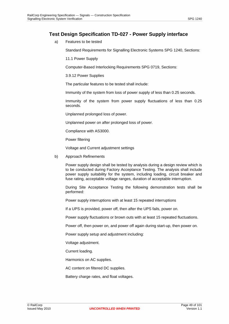
RailCorp Engineering Specification — Signals — Construction Specification Signalling Electronic System Verification SPG 1240
© RailCorp Page 49 of 101 Issued May 2010 UNCONTROLLED WHEN PRINTED Version 1.1
Test Design Specification TD-027 - Power Supply interface a) Features to be tested
Standard Requirements for Signalling Electronic Systems SPG 1240, Sections:
11.1 Power Supply
Computer-Based Interlocking Requirements SPG 0719, Sections:
3.9.12 Power Supplies
The particular features to be tested shall include:
Immunity of the system from loss of power supply of less than 0.25 seconds.
Immunity of the system from power supply fluctuations of less than 0.25 seconds.
Unplanned prolonged loss of power.
Unplanned power on after prolonged loss of power.
Compliance with AS3000.
Power filtering
Voltage and Current adjustment settings
b) Approach Refinements
Power supply design shall be tested by analysis during a design review which is to be conducted during Factory Acceptance Testing. The analysis shall include power supply suitability for the system, including loading, circuit breaker and fuse rating, acceptable voltage ranges, duration of acceptable interruption.
During Site Acceptance Testing the following demonstration tests shall be performed:
Power supply interruptions with at least 15 repeated interruptions
If a UPS is provided, power off, then after the UPS fails, power on.
Power supply fluctuations or brown outs with at least 15 repeated fluctuations.
Power off, then power on, and power off again during start-up, then power on.
Power supply setup and adjustment including:
Voltage adjustment.
Current loading.
Harmonics on AC supplies.
AC content on filtered DC supplies.
Battery charge rates, and float voltages.
RailCorp Engineering Specification — Signals — Construction Specification Signalling Electronic System Verification SPG 1240
© RailCorp Page 50 of 101 Issued May 2010 UNCONTROLLED WHEN PRINTED Version 1.1
Generally power supply interruptions are by operation of the incoming circuit breakers, but if this does not provide sufficient precision then the interruption will have to be made via a timer relay etc.
Generally power supply fluctuations are produced by loosening a connection in the power distribution and wiggling it, but if this does not provide sufficient precision then the interruption will have to be made via a variable auto-transformer or series resistor switched in and out of circuit.
All power supply disturbances shall be recorded to allow confirmation that the disturbance does not exceed the limits.
Compliance with AS3000 shall be checked by inspection.
c) Associated Test Cases
The following Test Case shall be performed to test some of these features.
Immunity of the system from loss of power supply of less than 0.25 seconds. TC027INT
d) Feature Pass/Fail Criteria
Each feature must be tested and pass each individual test for the system to pass this test.

RailCorp Engineering Specification — Signals — Construction Specification Signalling Electronic System Verification SPG 1240
© RailCorp Page 51 of 101 Issued May 2010 UNCONTROLLED WHEN PRINTED Version 1.1
Test Design Specification TD-028 - Communications interface a) Features to be tested
Standard Requirements for Signalling Electronic Systems SPG 1240, Sections:
11.2 Communications
Computer-Based Interlocking Requirements SPG 0719, Sections:
3.9.11 Vital Communications Links
b) Approach Refinements
Each new communications link needs to be fully tested, regardless of whether or not the equipment has been previously type approved.
The system shall automatically recover within 1 second of when the disruption is stopped.
For analogue communications lines the tests should include :
Determine maximum noise level during a 24 hour period. Maximum should be less than 5 db above average noise level.
An average Signal to Noise level at worst case of greater than 25 db is required.
Modem transmit level is within accepted range for the Telecommunications line Provider
The Modem receive level is at least 10 db above the minimum receive level for the modem
Perform a BERT for the link. The link must have a Bit Error Rate Test result of less than one bit error in 1x107 bits.
Disruption of the connections at either end.
Disruption of the link, including interruptions of duration less than 0.2 seconds, and greater than 1 second, earth faults on either leg.
Disruptions of the modem power supplies, including interruptions of duration less than 0.2 seconds, and greater than 1 second.
Disruptions due to EMI via sources like handheld radio transmitters, and electro-mechanical equipment.
Monitor link operation for compliance with the specified protocol, including response to, and recovery from error conditions.
For fibre optic links the tests should include:
The Fibre Optic Modem receive level is at least 15 db above the minimum receive level for the modem.
Perform a BERT for the link. The link must have a Bit Error Rate Test result of less than one bit error in 1x108 bits.
Loss on the fibre optic link connections is less than 0.5 db per connection.
The fibre optic link passes OTDR tests.

RailCorp Engineering Specification — Signals — Construction Specification Signalling Electronic System Verification SPG 1240
© RailCorp Page 52 of 101 Issued May 2010 UNCONTROLLED WHEN PRINTED Version 1.1
For digital communications lines the tests should include :
Perform a BERT for the link. The link must have a Bit Error Rate Test result of less than one bit error in 1x108 bits.
Disruption of the link, including interruptions of duration less than 0.2 seconds, and greater than 1 second.
Disruptions of the modem power supplies, including interruptions of duration less than 0.2 seconds, and greater than 1 second.
Monitor link operation for compliance with the specified protocol, including response to, and recovery from error conditions.
Both analogue and digital communication links shall automatically recover from any disruption test.
Multi-drop communications links should have additional tests to determine that it is unlikely for a failure at one field station to disrupt the operation of the system as a whole and therefore fail other field stations.
These features are to be tested during Factory Acceptance Testing and during Site Acceptance Testing.
Communications design conformance to ISO OSI recommendations shall be tested by inspection of the communications design. The communications protocol shall be tested by inspection of the protocol documentation and by formal tests during Factory Acceptance Testing.
AUSTEL approval of modems, modem connections and power supply arrangements shall be checked by inspection during Factory Acceptance Testing.
The communications error rate shall be checked by formal tests when the system is installed on site using an appropriate tool such as a protocol analyser programmed to count errors or communications statistics provided by the system.
Each communications and data line shall be inspected for the inclusion of a monitor point.
c) Associated Test Cases
The following Test Cases shall be performed to test these features.
Modem approvals TC 028MOD
Design of communication protocols TC 028PRO
Design conformance to ISO OSI recommendations TC 028COM
Communications error rate TC 028ERR
Monitor points. TC 028MON
Recovery from disruptions TC 028DIS
Multi-drop links. TC 028MDL
d) Feature Pass/Fail Criteria
RailCorp Engineering Specification — Signals — Construction Specification Signalling Electronic System Verification SPG 1240
© RailCorp Page 53 of 101 Issued May 2010 UNCONTROLLED WHEN PRINTED Version 1.1
Each feature must be tested and pass each individual test for the system to pass this test.

RailCorp Engineering Specification — Signals — Construction Specification Signalling Electronic System Verification SPG 1240
© RailCorp Page 54 of 101 Issued May 2010 UNCONTROLLED WHEN PRINTED Version 1.1
Test Design Specification TD-029 - Signalling interface a) Features to be tested
Standard Requirements for Signalling Electronic Systems SPG 1240, Sections:
11.3 Signalling
Electrical compatibility of the interface.
b) Approach Refinements
These features are to be tested during Factory Acceptance Testing and during Site Acceptance Testing.
During Factory Acceptance Testing:
The interface to the signalling system shall be tested by analysis and inspection.
Operation at maximum, minimum, and nominal voltages shall be demonstrated.
Operating currents at maximum, minimum, and nominal voltages shall be tested by analysis.
Timing of inputs for immunity to contact debounce and electrical noise shall be tested by analysis and demonstration.
Timing of inputs to determine the minimum time an input must be in each state for it to be reliably detected in that state shall be tested by analysis and demonstration.
Component heat dissipation shall be tested by analysis.
A demonstration test of the correspondence of each signalling control.
During Site Acceptance Testing:
Inspection test to confirm installation in accordance with design.
A demonstration test of the correspondence of each signalling control operating through the complete system.
c) Associated Test Cases
The following Test Cases shall be performed to test some of these features.
Issue of controls TC029CTL
d) Feature Pass/Fail Criteria
Each feature must be tested and pass each individual test for the system to pass this test.

RailCorp Engineering Specification — Signals — Construction Specification Signalling Electronic System Verification SPG 1240
© RailCorp Page 55 of 101 Issued May 2010 UNCONTROLLED WHEN PRINTED Version 1.1
Test Design Specification TD-030 - User/Operator interface a) Features to be tested
Standard Requirements for Signalling Electronic Systems SPG 1240, Sections:
11.4 User/Operator interface
5.1 Documentation – General. (part)
b) Approach Refinements
The ergonomic design shall be reviewed while performing tests during Factory Acceptance Testing and during Site Acceptance Testing. All operational tasks of the system shall be demonstrated as per the system documentation.
The system shall be reviewed during Factory Acceptance Testing to confirm that the users and/or operators of the system are not required to perform repetitive tasks that do not require the user or operator to use their expertise. This review is intended to determine that a reasonable level of automation is provided so that the productivity of the User/Operator is not un-necessarily limited by the system.
The change over between users shall be demonstrated in a factory test set up using formal tests. While the system is in the process of changing users, several changes of state and alarms shall be simulated.
A stopwatch will be used for any time measurements.
This Test Design is intended to cover general issues for the User/Operator interface. Test Design 038 covers the specific requirements for a Signalling Operator Interface.
c) Associated Test Cases
The following Test Cases shall be performed during Factory Acceptance Testing to test these features.
No loss of information or alarms during change of users and or operators. TC030CHG
“log on” / “log off” procedure to take less than 1 minute. TC030LOG
d) Feature Pass/Fail Criteria
Each feature must be tested and pass each individual test for the system to pass this test.

RailCorp Engineering Specification — Signals — Construction Specification Signalling Electronic System Verification SPG 1240
© RailCorp Page 56 of 101 Issued May 2010 UNCONTROLLED WHEN PRINTED Version 1.1
Test Design Specification TD-031 - Other Interfaces a) Features to be tested
Standard Requirements for Signalling Electronic Systems SPG 1240, Sections:
11.5 Other Interfaces
b) Approach Refinements
This feature is to be tested during Factory Acceptance Testing.
100% test by demonstration of each function of each other interface,
Each other interface shall be tested by analysis for compatibility.
Each other interface shall be sample demonstration tested over the full range of conditions.
Each other interface shall be tested by demonstration for correspondence for information passed across the interface.
c) Associated Test Cases
The following Test Cases shall be performed to test these features.
Other Interface design and approval check. TC031INT
d) Feature Pass/Fail Criteria
Each feature must be tested and pass each individual test for the system to pass this test.

RailCorp Engineering Specification — Signals — Construction Specification Signalling Electronic System Verification SPG 1240
© RailCorp Page 57 of 101 Issued May 2010 UNCONTROLLED WHEN PRINTED Version 1.1
Test Design Specification TD-032 - Integrity a) Features to be tested
Standard Requirements for Signalling Electronic Systems SPG 1240, Sections:
12 Integrity
Suitability of integrity requirements
b) Approach Refinements
These features are to be tested during Factory Acceptance Testing.
An analysis of the system is carried out as a risk assessment to identify integrity issues. The method for controlling each risk is then tested by analysis, inspection, or demonstration.
Particular integrity issues that are to be tested include:
Spurious controls due to :
Incorrect storage of controls in the system,
Incorrect storage of controls in a standby system,
Communications errors,
Incorrect logic evaluation,
Software errors or faults,
Data errors,
Interface incompatibilities.
Displaying incorrect information that is not obviously incorrect due:
Communications errors,
Incorrect logic evaluation,
Software errors or faults,
Data errors,
Interface incompatibilities.
Unauthorised access due to:
Physical access,
Electronic access.
An independent person shall perform a complete integrity test of the data for the system. The level of integrity tested shall be based on the risk assessment.

RailCorp Engineering Specification — Signals — Construction Specification Signalling Electronic System Verification SPG 1240
© RailCorp Page 58 of 101 Issued May 2010 UNCONTROLLED WHEN PRINTED Version 1.1
c) Associated Test Cases
The following Test Cases shall be performed to test these features.
Integrity of facilities. TC032INT
Likelihood for displaying incorrect information. TC032IND
Likelihood for issuing spurious controls. TC032CTL
Level of risk for the proposed usage of the system. TC032RSK
Protection against unauthorised access. TC032PRT
Logic Evaluation TC032EVL
d) Feature Pass/Fail Criteria
Each feature must be tested and pass each individual test for the system to pass this test.
RailCorp Engineering Specification — Signals — Construction Specification Signalling Electronic System Verification SPG 1240
© RailCorp Page 59 of 101 Issued May 2010 UNCONTROLLED WHEN PRINTED Version 1.1
Test Design Specification TD-033 - Occupational Health and Safety
a) Features to be tested
Standard Requirements for Signalling Electronic Systems SPG 1240, Section:
13. Occupational Health and Safety
b) Approach Refinements
This feature is to be tested during Factory Acceptance Testing and Site Acceptance Testing.
The standards for Occupational Health and Safety to which system must comply are first identified. The system design shall then be reviewed for compliance
The requirement shall be tested by review and inspection and the results produced as a report identifying the issues and how they have been addressed.
c) Associated Test Cases
There are no associated test cases.
d) Feature Pass/Fail Criteria
The report shall demonstrate how the requirements have been met for the system to pass this test.

RailCorp Engineering Specification — Signals — Construction Specification Signalling Electronic System Verification SPG 1240
© RailCorp Page 60 of 101 Issued May 2010 UNCONTROLLED WHEN PRINTED Version 1.1
Test Design Specification TD-034 - Maintenance aspects a) Features to be tested
Standard Requirements for Signalling Electronic Systems SPG 1240, Sections:
14.1 Maintainability
5.5 Maintenance Manual
5.10 Technical Maintenance Plan (TMP)
Computer-Based Interlocking Requirements SPG 0719, Sections:
4.4.13 Maintainability Demonstration
4.4.14 Maintainability Monitoring
b) Approach Refinements
These features are to be tested during Factory Acceptance Testing.
Test by demonstration of each maintenance action in the TMP.
Test by demonstration of each significant corrective maintenance action in accordance with the documentation and items supplied.
Test by demonstration of each test facility.
Any specialised equipment required shall be noted and supply checked during the test on deliverables.
The Maintainability Monitoring shall be carried out as part of Test Design Specification 008 Reliability.
c) Associated Test Cases
There is no generic test case provided for this test design.
d) Feature Pass/Fail Criteria
Each feature must be tested and pass each individual test for the system to pass this test.

RailCorp Engineering Specification — Signals — Construction Specification Signalling Electronic System Verification SPG 1240
© RailCorp Page 61 of 101 Issued May 2010 UNCONTROLLED WHEN PRINTED Version 1.1
Test Design Specification TD-035 - Diagnostics a) Features to be tested
Standard Requirements for Signalling Electronic Systems SPG 1240, Sections:
14.2 Diagnostic Indications
14.3 Diagnostic test facilities and data
5.5 Maintenance Manual
b) Approach Refinements
These features are to be tested during Factory Acceptance Testing.
The system and all sub-systems are to be identified, then for each system all diagnostic indications are to be identified and fully corresponded in a demonstration test.
All causes of diagnostic indications are then identified. The procedures for determining the cause of diagnostic indications are then reviewed against the causes identified by an inspection test.
Diagnostic data collected by the system for a period of three days shall be collected and tested by analysis. The data shall contain records of any problems encountered and all self-tests performed. The diagnostic data shall at least include:
Data communications statistics, for each communications node.
System, and sub-system start-up
Software errors detected by the system
Hardware errors detected by the system
Condition Based Maintenance data for the system and equipment controlled by the system.
c) Associated Test Cases
There are no associated Test Cases.
d) Feature Pass/Fail Criteria
Each feature must be tested and pass each individual test for the system to pass this test.

RailCorp Engineering Specification — Signals — Construction Specification Signalling Electronic System Verification SPG 1240
© RailCorp Page 62 of 101 Issued May 2010 UNCONTROLLED WHEN PRINTED Version 1.1
Test Design Specification TD-036 - Deliverables a) Features to be tested
Standard Requirements for Signalling Electronic Systems SPG 1240, Sections:
16 Deliverables.
Each deliverable has been received and is the correct version and is in good condition.
b) Approach Refinements
These features are to be tested during Site Acceptance Testing.
The supply of the following shall be checked where applicable:
System Hardware has been correctly installed, configured and tested.
All Spares have been handed over and are compatible with the system.
All software, firmware, and data is the approved tested version, and properly installed.
A copy of all source code on magnetic media.
A copy of all aids used in creating executable’s on magnetic media.
A copy of all aids used in the formal testing of the system on magnetic media.
Printed copies of the documentation as well as a copy on magnetic media.
Licenses.
All documentation initially supplied with the purchased/delivered items, for example the manual for a monitor, or modem.
Test equipment if required.
c) Associated Test Cases
There are no associated test cases.
d) Feature Pass/Fail Criteria
Each feature must be tested and pass each individual test for the system to pass this test.

RailCorp Engineering Specification — Signals — Construction Specification Signalling Electronic System Verification SPG 1240
© RailCorp Page 63 of 101 Issued May 2010 UNCONTROLLED WHEN PRINTED Version 1.1
Test Design Specification TD-037 - System Confidence test a) Features to be tested
The system operating normally including:
Each Operator command
Each Maintenance command
Each indication type
Each output type
System responsiveness
b) Approach Refinements
This feature is to be tested during each testing phase and during in-service operation of the system. This test is to be used after any alteration to the system either by modification or corrective action.
Each functional element of the system shall be sample tested, with a minimum of 2 samples.
All system status indications and diagnostic indications shall be checked to ensure system is operating without error.
Search log files for "fault" and "error" and analyse any occurrences for problems.
Monitor memory usage on each for stability.
Monitor disk space usage to confirm that it is within limits and that disk space usage is stable.
Check that all parts or the system have the correct version of software and data.
The System Confidence testing must provide a 95% confidence level that at the completion of the System Confidence testing there will not be any undetected faults or problems that could cause an impact on the utilisation of RailCorp 's infrastructure.
c) Associated Test Cases
There are no associated test cases.
d) Feature Pass/Fail Criteria
Each feature must be tested and pass each individual test for the system to pass this test.

RailCorp Engineering Specification — Signals — Construction Specification Signalling Electronic System Verification SPG 1240
© RailCorp Page 64 of 101 Issued May 2010 UNCONTROLLED WHEN PRINTED Version 1.1
Test Design Specification TD-038 – Signalling Operator Interface
a) Features to be tested
Each performance requirement nominated in RailCorp Specification Signaller Operator Interface ESG 0004.
b) Approach Refinements
Each of the performance requirements shall be tested in the normal operating situation, with the normal expected workload. Failure conditions and abnormal situations will not be considered for the testing of compliance with the performance requirements, unless they are specifically mentioned in the requirement.
Time measurement will be made with a stopwatch and repeated at least 5 times and averaged. An allowance of 0.25 seconds may be made for the reaction time of the person using the stopwatch.
A general usability demonstration shall be performed which demonstrates that the Signaller can comfortably perform their duties using the system provided.
c) Associated Test Cases
There are no associated test cases.
d) Feature Pass/Fail Criteria
Each feature must be tested and pass each individual test for the system to pass this test.

RailCorp Engineering Specification — Signals — Construction Specification Signalling Electronic System Verification SPG 1240
© RailCorp Page 65 of 101 Issued May 2010 UNCONTROLLED WHEN PRINTED Version 1.1
Test Design Specification TD-039 – Train Control System a) Features to be tested
Train Control systems are to be tested for the following features if that feature is provided as part of the system:
Train descriptions
range of descriptions available (number of characters, character set)
accuracy of tracking trains under normal conditions and reasonably expected indication fault conditions (eg intermittent track bob, point detection bounce, etc), and the full range of train movements
merging trains
splitting trains
changing descriptions
Route storage
control table test
immunity from momentary change of state of an input
order of setting when several routes become available, with several conflicting routes stored
storage for following and opposing moves with several conflicting routes stored
ability to set routes with indications failures external to the route.
Train reporting
configuration of the reporting points
reports are suitable for each user group
arrival and departure points
all trains (timetabled and non-timetabled) being reported
trains passing different reporting points at the same time
trains running on the wrong line or in a different direction to normal
display format
ability to view recent history with little or no effort
printing and printed report format
historical records
Timetabling
Automatic Route Setting
Interfaces to other computer systems or equipment

RailCorp Engineering Specification — Signals — Construction Specification Signalling Electronic System Verification SPG 1240
© RailCorp Page 66 of 101 Issued May 2010 UNCONTROLLED WHEN PRINTED Version 1.1
b) Approach Refinements
The functionality of each Train Control system is to be analysed and any features not listed as a feature to be tested that is not covered elsewhere in this test plan is to be included as a feature to be tested.
Each feature is to be tested in a range of real world situations, with a set of expected normal conditions, fault conditions, extreme inputs.
Each feature is to be examined for a set of stress conditions and stress conditions repeated sufficiently to demonstrate that the required reliability can be met.
c) Associated Test Cases
There are no associated test cases.
d) Feature Pass/Fail Criteria
Each feature must be tested and pass each individual test for the system to pass this test.

RailCorp Engineering Specification — Signals — Construction Specification Signalling Electronic System Verification SPG 1240
© RailCorp Page 67 of 101 Issued May 2010 UNCONTROLLED WHEN PRINTED Version 1.1
Appendix D Test Case Specifications This appendix contains each of the Test Case Specifications. Each Test Case Specification commences on a new page.

RailCorp Engineering Specification — Signals — Construction Specification Signalling Electronic System Verification SPG 1240
© RailCorp Page 68 of 101 Issued May 2010 UNCONTROLLED WHEN PRINTED Version 1.1
Test Case Specification TC003LBT - Logger boundary testing a) Test Items
Duration of log.
Stress (maximum loading).
Log size reaching maximum capacity.
The logger is being tested for compliance with Standard Requirements for Signalling Electronic Systems SPG 1240 section 4.3.
b) Input Specifications
The expected load of the system shall be simulated.
The system shall be subjected to the maximum load.
The system shall be run with the log at maximum capacity.
c) Output Specifications
The duration of the log shall be greater than 14 days for the expected load of the system.
The system shall not lose any events or record incorrect times when under maximum load.
The performance of the system shall not be degraded by the log being its maximum size.
d) Environmental Needs
The system is installed in a factory acceptance test set up.
e) Special Procedural Requirements
A method is required for simulating expected and maximum loads on the system.
f) Intercase Dependencies
The basic factory system installation, set up and adjustment must have been completed.

RailCorp Engineering Specification — Signals — Construction Specification Signalling Electronic System Verification SPG 1240
© RailCorp Page 69 of 101 Issued May 2010 UNCONTROLLED WHEN PRINTED Version 1.1
Test Case Specification TC003LCF - Configuration of log. a) Test Items
The configuration of the logger is being tested for compliance with Standard Requirements for Signalling Electronic Systems SPG 1240 section 4.3.
b) Input Specifications
The logging system as provided by the Supplier.
3. Output Specifications
A fully operational logger that is correctly configured according to the supplied documentation.
c) Environmental Needs
The system is installed in a factory acceptance test set up.
d) Special Procedural Requirements
There are no special procedural requirements.
e) Intercase Dependencies
The basic factory system installation, set up and adjustment must have been completed.

RailCorp Engineering Specification — Signals — Construction Specification Signalling Electronic System Verification SPG 1240
© RailCorp Page 70 of 101 Issued May 2010 UNCONTROLLED WHEN PRINTED Version 1.1
Test Case Specification TC003LGR Logger review. a) Test Items
Durability of log.
Producing log reports.
Readability of log reports.
The logger is being tested for compliance with Standard Requirements for Signalling Electronic Systems SPG 1240 section 4.3 .
b) Input Specifications
All types of inputs and states shall be simulated.
A log report of the events shall be produced.
c) Output Specifications
The performance of the system shall not be degraded by accessing the log.
The log report shall be detailed, with minimal need to use cross-reference material for the maintainer of the system to diagnose faults and shall require approval from RailCorp’s Representative.
d) Environmental Needs
The system is installed in a factory acceptance test set up.
e) Special Procedural Requirements
A method is required for simulating expected and maximum loads on the system.
f) Intercase Dependencies
The basic factory system installation, set up and adjustment must have been completed.

RailCorp Engineering Specification — Signals — Construction Specification Signalling Electronic System Verification SPG 1240
© RailCorp Page 71 of 101 Issued May 2010 UNCONTROLLED WHEN PRINTED Version 1.1
Test Case Specification - TC003LGT Logger timing a) Test Items
The logger timing is being tested for compliance with Standard Requirements for Signalling Electronic Systems SPG 1240 section 4.3.
b) Input Specifications
Inputs shall be changed by an accurate means, or input changes measured by an accurate means for comparison to the logger.
The logger shall be run for three or more days, to check the drift of the clock.
c) Output Specifications
The accuracy of the log shall be to 1 second or better and have a resolution of at least one second.
All changes of state of inputs and outputs of duration greater than 0.2 seconds shall be logged.
The reference clock shall not lose or gain more than one second a day.
d) Environmental Needs
The system is installed in a factory acceptance test set up.
A method of accurately changing inputs or accurately measuring input changes is required.
An accurate clock is required to test the time drift.
e) Special Procedural Requirements
There are no special procedural requirements.
f) Intercase Dependencies
The basic factory system installation, set up and adjustment must have been completed.

RailCorp Engineering Specification — Signals — Construction Specification Signalling Electronic System Verification SPG 1240
© RailCorp Page 72 of 101 Issued May 2010 UNCONTROLLED WHEN PRINTED Version 1.1
Test Case Specification - TC003LRA Remote access of log. a) Test Items
The logger remote access is being tested for compliance with Standard Requirements for Signalling Electronic Systems SPG 1240 section 4.3.
b) Input Specifications
Remote access of logs, setting of clock and all other functions of remote access shall be exercised.
c) Output Specifications
All functions of remote access shall function correctly.
d) Environmental Needs
The system is installed in a factory acceptance test set up.
e) Special Procedural Requirements
There are no special procedural requirements.
f) Intercase Dependencies
The basic factory system installation, set up and adjustment must have been completed.

RailCorp Engineering Specification — Signals — Construction Specification Signalling Electronic System Verification SPG 1240
© RailCorp Page 73 of 101 Issued May 2010 UNCONTROLLED WHEN PRINTED Version 1.1
Test Case Specification - TC003LTD review of a 3 day period of the actual log.
a) Test Items
The logger remote access is being tested for compliance with Standard Requirements for Signalling Electronic Systems SPG 1240 section 4.3.
b) Input Specifications
The system shall be run under normal operating conditions for three days.
c) Output Specifications
The log shall be reviewed, with no inconsistencies detected.
d) Environmental Needs
The system is installed in its final configuration.
e) Special Procedural Requirements
There are no special procedural requirements.
f) Intercase Dependencies
The system installation, set up and adjustment must have been completed.

RailCorp Engineering Specification — Signals — Construction Specification Signalling Electronic System Verification SPG 1240
© RailCorp Page 74 of 101 Issued May 2010 UNCONTROLLED WHEN PRINTED Version 1.1
Test Case Specification 004SS - TC 004SS System health indication and procedures for determining the cause of a reduced health state.
a) Test Items
Each system and sub-system is being tested for compliance with Standard Requirements for Signalling Electronic Systems SPG 1240 section 4.4).
b) Input Specifications
The system and all sub-systems are to be identified.
For the system and all sub-systems all health states are to be identified.
c) Output Specifications
The system indicates all health states correctly for all systems and all sub-systems.
The procedures for determining the cause of the reduced health states confirms the correct cause for the reduced health state.
d) Environmental Needs
The system is installed in a factory acceptance test set up.
e) Special Procedural Requirements
The procedures for determining the cause of reduced health states are required
A method of causing all health states to occur for the system and all sub-systems is required.
f) Intercase Dependencies
The basic system installation, setup and adjustment must have been completed.

RailCorp Engineering Specification — Signals — Construction Specification Signalling Electronic System Verification SPG 1240
© RailCorp Page 75 of 101 Issued May 2010 UNCONTROLLED WHEN PRINTED Version 1.1
Test Case Specification - TC 005CIC Control Indication correspondence test.
a) Test Items
The control indications used by the system are being tested for compliance with Standard Requirements for Signalling Electronic Systems SPG 1240 section 4.5).
b) Input Specifications
The controls shall be driven so as to create each control indication in each of its states.
c) Output Specifications
Each control indication shall be displayed correctly.
d) Environmental Needs
For this test the system shall be operating in a complete configuration in a factory test set up.
This test shall be repeated when the system is installed in its final configuration, pre-commissioning.
e) Special Procedural Requirements
There are no special procedural requirements.
f) Intercase Dependencies
The basic system installation, setup and adjustment must have been completed.

RailCorp Engineering Specification — Signals — Construction Specification Signalling Electronic System Verification SPG 1240
© RailCorp Page 76 of 101 Issued May 2010 UNCONTROLLED WHEN PRINTED Version 1.1
Test Case Specification TC 005ICT Indication correspondence test.
a) Test Items
The indications used by the system are being tested for compliance with Standard Requirements for Signalling Electronic Systems SPG 1240 section 4.5).
b) Input Specifications
The inputs shall be driven so as to create each indication in each of its states.
c) Output Specifications
Each indication shall be displayed correctly.
d) Environmental Needs
For this test the system shall be operating in a complete configuration in a factory test set up.
This test shall be repeated when the system is installed in its final configuration, pre-commissioning.
e) Special Procedural Requirements
There are no special procedural requirements.
f) Intercase Dependencies
The basic system installation, setup and adjustment must have been completed.

RailCorp Engineering Specification — Signals — Construction Specification Signalling Electronic System Verification SPG 1240
© RailCorp Page 77 of 101 Issued May 2010 UNCONTROLLED WHEN PRINTED Version 1.1
Test Case Specification - TC 005IND Review of indications. a) Test Items
The indications used by the system are being tested for compliance with Standard Requirements for Signalling Electronic Systems SPG 1240 section 4.5).
b) Input Specifications
Samples of all the states of indications, including indication of controls, used by the system are submitted to RailCorp’s Representative for review.
c) Output Specifications
Where required the indications shall be modified to meet the needs of the client.
d) Environmental Needs
For this test the system shall be operating in a complete configuration in a factory test set up.
e) Special Procedural Requirements
There are no special procedural requirements.
f) Intercase Dependencies
The basic system installation, setup and adjustment must have been completed.

RailCorp Engineering Specification — Signals — Construction Specification Signalling Electronic System Verification SPG 1240
© RailCorp Page 78 of 101 Issued May 2010 UNCONTROLLED WHEN PRINTED Version 1.1
Test Case Specification TC 005REP Review of reports. a) Test Items
The reports produced by the system are being tested for compliance with Standard Requirements for Signalling Electronic Systems SPG 1240 section 4.5).
b) Input Specifications
Samples of all the reports the system can produce are submitted to RailCorp’s Representative for review.
c) Output Specifications
Where required the reports shall be modified to meet the needs of the client.
d) Environmental Needs
For this test the system shall be operating in a complete configuration in a factory test set up.
e) Special Procedural Requirements
There are no special procedural requirements.
f) Intercase Dependencies
The basic system installation, setup and adjustment must have been completed.

RailCorp Engineering Specification — Signals — Construction Specification Signalling Electronic System Verification SPG 1240
© RailCorp Page 79 of 101 Issued May 2010 UNCONTROLLED WHEN PRINTED Version 1.1
Test Case Specification - TC 007CCT Command completion time.
a) Test Items
The command completion time of the system is being tested for compliance with Standard Requirements for Signalling Electronic Systems SPG 1240 section 4.7 e).
The command completion time shall be less than 2 seconds.
Processing of report commands shall be completed within 20 seconds.
b) Input Specifications
A set of commands that represents each type of control, function or report is chosen.
Each of these commands is issued 10 times and the time that the system takes to complete the command is recorded.
c) Output Specifications
The times recorded for the command completion times are all less than 2 seconds.
The times recorded for processing of report commands are all less than 20 seconds.
d) Environmental Needs
For this test the system shall be operating in a complete configuration in a factory test set up.
This test is repeated with the system under simulated maximum loading.
This test is repeated when the system is installed in its final configuration on site, prior to commissioning.
e) Special Procedural Requirements
There are no special procedural requirements.
f) Intercase Dependencies
The basic system installation, setup and adjustment must have been completed.
RailCorp Engineering Specification — Signals — Construction Specification Signalling Electronic System Verification SPG 1240
© RailCorp Page 80 of 101 Issued May 2010 UNCONTROLLED WHEN PRINTED Version 1.1
Test Case Specification - TC 007CIT Control indication time. a) Test Items
The control indication time of the system is being tested for compliance with Standard Requirements for Signalling Electronic Systems SPG 1240 section 4.7 d).
The control indication time shall be less than 2.5 seconds.
b) Input Specifications
A set of outputs that represents each type of output and each ‘station’ is chosen.
The control for each of these outputs is toggled 10 times and the time that the system takes to process or deliver the resultant output and display an indication in response is recorded.
c) Output Specifications
The times recorded for the control indications are all less than 2.5 seconds.
d) Environmental Needs
For this test the system shall be operating in a complete configuration in a factory test set up.
This test is repeated with the system under simulated maximum loading.
This test is repeated when the system is installed in its final configuration on site prior to commissioning.
A method of issuing controls is required.
e) Special Procedural Requirements
There are no special procedural requirements.
f) Intercase Dependencies
The basic system installation, setup and adjustment must have been completed.

RailCorp Engineering Specification — Signals — Construction Specification Signalling Electronic System Verification SPG 1240
© RailCorp Page 81 of 101 Issued May 2010 UNCONTROLLED WHEN PRINTED Version 1.1
Test Case Specification - TC 007CRT Control response time. a) Test Items
The control response time of the system is being tested for compliance with Standard Requirements for Signalling Electronic Systems SPG 1240 section 4.7 c).
The control response time shall be less than one second.
b) Input Specifications
A set of outputs that represents each type of output and each ‘station’ is chosen.
The control for each of these outputs is toggled 10 times and the time that the system takes to process or deliver the resultant output is recorded.
c) Output Specifications
The times recorded for the control responses are all less than one second.
d) Environmental Needs
For this test the system shall be operating in a complete configuration in a factory test set up.
This test is repeated with the system under simulated maximum loading.
This test is repeated when the system is installed in its final configuration on site, prior to commissioning.
A method of issuing controls is required.
e) Special Procedural Requirements
There are no special procedural requirements.
f) Intercase Dependencies
The basic system installation, set up and adjustment must have been completed.

RailCorp Engineering Specification — Signals — Construction Specification Signalling Electronic System Verification SPG 1240
© RailCorp Page 82 of 101 Issued May 2010 UNCONTROLLED WHEN PRINTED Version 1.1
Test Case Specification - TC 007IRT Indication response time a) Test Items
The indication response time of the system is being tested for compliance with Standard Requirements for Signalling Electronic Systems SPG 1240 section 4.7 b).
The indication response time shall be less than one second.
b) Input Specifications
A set of inputs that represents each type of input and each ‘station’ is chosen.
The input controlling each of these indications is toggled 10 times and the time that the system takes to display or deliver these indication changes is recorded.
c) Output Specifications
The times recorded for the change of state are all less than one second.
d) Environmental Needs
For this test the system shall be operating in a complete configuration in a factory test set up.
This test is repeated with the system under simulated maximum loading.
This test is repeated when the system is installed in its final configuration on site prior to commissioning.
A method of simulating changes on input states is required.
e) Special Procedural Requirements
There are no special procedural requirements.
f) Intercase Dependencies
The basic system installation, setup and adjustment must have been completed.

RailCorp Engineering Specification — Signals — Construction Specification Signalling Electronic System Verification SPG 1240
© RailCorp Page 83 of 101 Issued May 2010 UNCONTROLLED WHEN PRINTED Version 1.1
Test Case Specification - TC 007UDR Update dynamic report time.
a) Test Items
The update dynamic report time of the system is being tested for compliance with Standard Requirements for Signalling Electronic Systems SPG 1240 section 4.7 f).
The update dynamic report time shall be less than 1.5 seconds.
b) Input Specifications
A set of reports that represents each type of report is chosen.
Each of these reports is updated 10 times and the time that the system takes to update the report is recorded.
c) Output Specifications
The times recorded for the update of dynamic reports are all less than 1.5 seconds.
d) Environmental Needs
For this test the system shall be operating in a complete configuration in a factory test set up.
This test is repeated with the system under simulated maximum loading.
This test is repeated when the system is installed in its final configuration on site prior to commissioning.
e) Special Procedural Requirements
There are no special procedural requirements.
f) Intercase Dependencies
The basic system installation, setup and adjustment must have been completed.

RailCorp Engineering Specification — Signals — Construction Specification Signalling Electronic System Verification SPG 1240
© RailCorp Page 84 of 101 Issued May 2010 UNCONTROLLED WHEN PRINTED Version 1.1
Test Case Specification - TC 027INT Immunity of the system from loss of power supply of less than 0.25 seconds.
a) Test Items
Each power supply interface to the system is being tested for interruptions in compliance with Standard Requirements for Signalling Electronic Systems SPG 1240 section 11.1 e).
Power supply interfaces are normally at 120 volt AC or 240 volt AC and are represented by a circuit breaker.
b) Input Specifications
An interruption to the Main Power supply for each site with a duration of greater than 0.15 seconds and less than 0.25 seconds.
Observe the effect on the local and any remote site.
Repeat the disruption 15 times.
Cause at least 5 disruptions in one minute.
c) Output Specifications
All of the system continues to operate normally with no detectable interruption to operation or errors reported for power supply interruptions of less than the acceptable value.
d) Environmental Needs
The system is installed in its final configuration.
The main power supply is monitored after the point at which the disruption will occur so that the disruption and duration of the disruption is recorded.
A method of causing disruptions of greater than 0.15 seconds and less than 0.25 seconds is required.
e) Special Procedural Requirements
There are no special procedural requirements.
f) Intercase Dependencies
The basic system installation, setup and adjustment must have been completed.
The initial operational tests must have been completed, as well as the Power supply setup and adjustment tests because the system needs to be fully operational for this test.
Test Case Specification - TC 028COM Design conformance to ISO OSI recommendations.
g) Test Items
Each communications protocol used by the system is being tested for compliance with Standard Requirements for Signalling Electronic Systems SPG 1240 section 11.2 a).

RailCorp Engineering Specification — Signals — Construction Specification Signalling Electronic System Verification SPG 1240
© RailCorp Page 85 of 101 Issued May 2010 UNCONTROLLED WHEN PRINTED Version 1.1
h) Input Specifications
The communications system design.
i) Output Specifications
The communications protocol conforms to the recommendations of the International Standards Organisation (ISO) Open Systems Interconnection (OSI) model.
j) Environmental Needs
The communications system design is complete and is the same as the system that will be installed.
k) Special Procedural Requirements
There are no special procedural requirements.
l) Intercase Dependencies
There are no intercase dependencies requirements.

RailCorp Engineering Specification — Signals — Construction Specification Signalling Electronic System Verification SPG 1240
© RailCorp Page 86 of 101 Issued May 2010 UNCONTROLLED WHEN PRINTED Version 1.1
Test Case Specification - TC 028DIS Recovery from disruptions. a) Test Items
Each communications line used by the system is being tested for compliance with Standard Requirements for Signalling Electronic Systems SPG 1240 section 11.2.
b) Input Specifications
A protocol analyser is attached to the communications link.
The following disruptions are repeated for each end of each communications line.
Interruptions of less than 0.2 seconds duration.
Interruptions of greater than 1 second duration.
Earth faults on either leg.
Disruptions of the modem power supplies of less than 0.2 seconds.
Disruptions of the modem power supplies of greater than 1 second.
Disruptions due to EMI via sources like handheld radio transmitters, and electro-mechanical equipment.
c) Output Specifications
The communication link recovers for each of the disruptions.
d) Environmental Needs
The system is installed in its final configuration.
e) Special Procedural Requirements
A method of accurately disrupting communications links and power supplies is required.
f) Intercase Dependencies
The initial operational tests must have been completed, as well as the communications setup and adjustment tests because the system needs to be fully operational for this test.
RailCorp Engineering Specification — Signals — Construction Specification Signalling Electronic System Verification SPG 1240
© RailCorp Page 87 of 101 Issued May 2010 UNCONTROLLED WHEN PRINTED Version 1.1
Test Case Specification - TC 028ERR Communications error rate.
a) Test Items
Each communications line used by the system is being tested for compliance with Standard Requirements for Signalling Electronic Systems SPG 1240 section 11.2 f.
b) Input Specifications
The average and maximum noise levels are determined for a 24 hour period.
The signal and noise levels are recorded.
An OTDR shall be used on optical fibre links.
c) Output Specifications
The maximum noise level is less than 5dB above the average noise level.
The average signal to noise level is greater than 25dB.
The modem transmit level is within accepted range of the telecommunications line provider.
The modem receive level is at least 10dB above the minimum receive level of the modem.
The link must have a bit error rate of less than one bit error in 1 x 107 bits.
For optical fibre modems and links.
The receive level is at least 15 dB above the minimum receive level for the modem.
The link must have a bit error rate of less than one bit error in 1 x 108 bits.
Loss on the optic fibre link connections is less than 0.5 dB per connection.
The fibre optic link passes OTDR tests.
For digital communications links
The link must have a bit error rate of less than one bit error in 1 x 108 bits.
d) Environmental Needs
The system is installed in its final configuration.
A protocol analyser is attached to the communications link.
e) Special Procedural Requirements
There are no special procedural requirements.
f) Intercase Dependencies
The initial operational tests must have been completed, as well as the communications setup and adjustment tests because the system needs to be fully operational for this test.

RailCorp Engineering Specification — Signals — Construction Specification Signalling Electronic System Verification SPG 1240
© RailCorp Page 88 of 101 Issued May 2010 UNCONTROLLED WHEN PRINTED Version 1.1
Test Case Specification - TC 028MDL Multi-drop links. a) Test Items
Each communications line used by the system is being tested for compliance with Standard Requirements for Signalling Electronic Systems SPG 1240 section 11.2.
b) Input Specifications
Failure of any station.
c) Output Specifications
No disruption to the operation of the system other than loss of the one failed field station.
d) Environmental Needs
The system is installed in its final configuration.
e) Special Procedural Requirements
Ability to simulate all failure modes of a field station.
f) Intercase Dependencies
The initial operational tests must have been completed, as well as the communications setup and adjustment tests because the system needs to be fully operational for this test.

RailCorp Engineering Specification — Signals — Construction Specification Signalling Electronic System Verification SPG 1240
© RailCorp Page 89 of 101 Issued May 2010 UNCONTROLLED WHEN PRINTED Version 1.1
Test Case Specification - TC 028MOD Modem approvals. a) Test Items
Each modem type used by the system is to be tested for compliance with Standard Requirements for Signalling Electronic Systems SPG 1240 section 11.2 b and c).
b) Input Specifications
The modems used by the system and their power supply arrangements shall be inspected.
c) Output Specifications
Confirmation of AUSTEL approval.
Connection to the communications line confirmed to be via an AUSTEL approved 604 or RJ-11 data plug.
Modems powered from system’s power supply
d) Environmental Needs
The communications system design is complete and is the same as the system that will be installed.
e) Special Procedural Requirements
There are no special procedural requirements.
f) Intercase Dependencies
There are no intercase dependencies requirements.

RailCorp Engineering Specification — Signals — Construction Specification Signalling Electronic System Verification SPG 1240
© RailCorp Page 90 of 101 Issued May 2010 UNCONTROLLED WHEN PRINTED Version 1.1
Test Case Specification - TC 028MON Monitor points a) Test Items
Each communications line used by the system is being tested for compliance with Standard Requirements for Signalling Electronic Systems SPG 1240 section 11.2 g.
b) Input Specifications
The appropriate test equipment is attached to each communication and data line.
c) Output Specifications
Monitoring points provided on all communications and data lines.
Accessing monitoring points causes acceptable disruption to the system.
d) Environmental Needs
The system is installed in its final configuration.
e) Special Procedural Requirements
There are no special procedural requirements.
f) Intercase Dependencies
The initial operational tests must have been completed, as well as the communications setup and adjustment tests because the system needs to be fully operational for this test.

RailCorp Engineering Specification — Signals — Construction Specification Signalling Electronic System Verification SPG 1240
© RailCorp Page 91 of 101 Issued May 2010 UNCONTROLLED WHEN PRINTED Version 1.1
Test Case Specification - TC 028PRO Design of communications protocols for error detection and ensuring no loss if information or sequence.
a) Test Items
Each communications protocol used by the system is being tested for compliance with Standard Requirements for Signalling Electronic Systems SPG 1240 section 11.2 d and e).
b) Input Specifications
The communications protocol design.
A protocol analyser shall be connected to simulate the following: -
Loss of a packet
Corruption of a packet
Noise on control lines
The system shall be placed under load, with the communication system working at maximum throughput. The error rate is recorded for a minimum of 10 000 messages for point to multipoint links. The error rate is recorded for a minimum of 100 000 messages for point to point links.
c) Output Specifications
The communications protocol is designed to prevent information loss, and no sequence change to changes of state.
The system responds in accordance to the communications protocol design to the error conditions simulated by the protocol analyser.
The error rate is less than one invalid message in 1,000 for point-to-multipoint links and less than one invalid message in 10,000 for point-to-point links.
d) Environmental Needs
The system is installed in a factory acceptance test set up, with simulators to simulate field equipment not available for a factory test set up.
e) Special Procedural Requirements
There are no special procedural requirements.
f) Intercase Dependencies
There are no intercase dependencies requirements.
Test Case Specification - TC 029CTL Issue of controls
g) Test Items
The system is being tested for compliance with Standard Requirements for Signalling Electronic Systems SPG 1240 section 11.3 c).
h) Input Specifications

RailCorp Engineering Specification — Signals — Construction Specification Signalling Electronic System Verification SPG 1240
© RailCorp Page 92 of 101 Issued May 2010 UNCONTROLLED WHEN PRINTED Version 1.1
Each control shall be issued.
Indications from the field shall be changed in response to these controls.
Indications from the field shall be changed not in response to any control.
i) Output Specifications
Controls shall be sent only as the interlocking requires them, no additional controls shall be sent.
j) Environmental Needs
The system is installed in a factory acceptance test set up. A simulator is required for the inputs to the system, and to view the control outputs of the system.
k) Special Procedural Requirements
There are no special procedural requirements.
l) Intercase Dependencies
The basic system installation, setup and adjustment must have been completed.
All indication correspondence testing should have been completed.

RailCorp Engineering Specification — Signals — Construction Specification Signalling Electronic System Verification SPG 1240
© RailCorp Page 93 of 101 Issued May 2010 UNCONTROLLED WHEN PRINTED Version 1.1
Test Case Specification - TC 030CHG No loss of information or alarms during change of users and or operators
a) Test Items
The system is being tested for compliance with Standard Requirements for Signalling Electronic Systems SPG 1240 section 11.4 c).
b) Input Specifications
The current operator shall log off the system.
Various indications shall be changed, and alarms generated.
The operator shall log back on.
c) Output Specifications
The display shall show the correct state of the system. If the display is still visible during the time that no operator is logged on, then it shall show the correct indications when they occur.
When an operator logs back on, they shall receive any alarm that was generated during the time that no operator was logged on.
All history logs and alarm logs shall show all indications and alarms, regardless of whether an operator was logged on.
d) Environmental Needs
The system is installed in a factory acceptance test set up. A simulator is required for the inputs to the system.
e) Special Procedural Requirements
There are no special procedural requirements.
f) Intercase Dependencies
The basic system installation, setup and adjustment must have been completed.

RailCorp Engineering Specification — Signals — Construction Specification Signalling Electronic System Verification SPG 1240
© RailCorp Page 94 of 101 Issued May 2010 UNCONTROLLED WHEN PRINTED Version 1.1
Test Case Specification - TC 030LOG “log on” / “log off” procedure to take less than 1 minute.
a) Test Items
The system is being tested for compliance with Standard Requirements for Signalling Electronic Systems SPG 1240 section 11.4 d).
b) Input Specifications
The operator shall log off the system and a new operator shall log on. The time from when the first operator initiates the log off process to when the second operator has full control of their area of control shall be recorded.
c) Output Specifications
The time recorded shall be less than 1 minute.
d) Environmental Needs
The system is installed in a factory acceptance test set up.
e) Special Procedural Requirements
There are no special procedural requirements.
f) Intercase Dependencies
The basic system installation, setup and adjustment must have been completed.

RailCorp Engineering Specification — Signals — Construction Specification Signalling Electronic System Verification SPG 1240
© RailCorp Page 95 of 101 Issued May 2010 UNCONTROLLED WHEN PRINTED Version 1.1
Test Case Specification - TC 031INT Other Interface design and approval check.
a) Test Items
Each interface to the system, not covered by other tests, is being tested for interruptions in compliance with Standard Requirements for Signalling Electronic Systems SPG 1240 section 11.5).
b) Input Specifications
The interface design.
The RailCorp’s Representative's approval.
Function each feature of the interface.
c) Output Specifications
The interface operates according to the design.
d) Environmental Needs
The system is installed in a factory acceptance test set up.
If the interface can not be fully tested then this test is repeated on the system installed in its final configuration.
e) Special Procedural Requirements
There are no special procedural requirements.
f) Intercase Dependencies
The basic system installation, setup and adjustment must have been completed.
The initial operational tests must have been completed and adjustment tests because the system needs to be fully operational for this test.

RailCorp Engineering Specification — Signals — Construction Specification Signalling Electronic System Verification SPG 1240
© RailCorp Page 96 of 101 Issued May 2010 UNCONTROLLED WHEN PRINTED Version 1.1
Test Case Specification - TC 032CTL Likelihood for issuing spurious controls.
a) Test Items
The system is being tested for controls integrity in compliance with Standard Requirements for Signalling Electronic Systems SPG 1240 section 12 c).
b) Input Specifications
The design of the control system.
Operation of all the control system under all failure modes of the system.
c) Output Specifications
The system issues only the correct controls.
d) Environmental Needs
The system is installed in a factory acceptance test set up.
Where required this test is repeated on the system installed in its final configuration.
e) Special Procedural Requirements
There are no special procedural requirements.
f) Intercase Dependencies
The basic system installation, setup and adjustment must have been completed.
The initial operational tests must have been completed and adjustment tests because the system needs to be fully operational for this test.

RailCorp Engineering Specification — Signals — Construction Specification Signalling Electronic System Verification SPG 1240
© RailCorp Page 97 of 101 Issued May 2010 UNCONTROLLED WHEN PRINTED Version 1.1
Test Case Specification - TC 032EVL Logic Evaluation. a) Test Items
The system is being tested for integrity in compliance with Standard Requirements for Signalling Electronic Systems SPG 1240 section 12.
b) Input Specifications
The logic evaluation engine shall be provided with logic for the following conditions, and then stimulated with input changes to fully exercise the logic evaluation:
Recursive expressions.
Changes of state of inputs and outputs during any routine refresh or update process.
Change the state of an input used in a pair of logic expressions where the second expression changes an internal variable or intermediate state, and the first expression is for an output dependant on the internal variable or intermediate state.
General input changes with an input continuously changing at a 0.5 seconds ON and 0.5 seconds OFF.
A quick, double change of state of an input used in a complex set of logic expressions.
c) Output Specifications
The system outputs shall correctly reflect the state of the inputs based on the logic within the required system response time.
d) Environmental Needs
The system is installed in a factory acceptance test set up.
Where required this test is repeated on the system installed in its final configuration.
e) Special Procedural Requirements
There are no special procedural requirements.
f) Intercase Dependencies
The basic system installation, setup and adjustment must have been completed.
The initial operational tests must have been completed and adjustment tests because the system needs to be fully operational for this test.
Test Case Specification - TC 032IND Likelihood for displaying incorrect information.
g) Test Items
The system is being tested for display integrity in compliance with Standard Requirements for Signalling Electronic Systems SPG 1240 section 12 b).

RailCorp Engineering Specification — Signals — Construction Specification Signalling Electronic System Verification SPG 1240
© RailCorp Page 98 of 101 Issued May 2010 UNCONTROLLED WHEN PRINTED Version 1.1
h) Input Specifications
The design of the display system.
Operation of all the display system under all failure modes of the system.
i) Output Specifications
The display system operates correctly, system indicates when display is not valid.
j) Environmental Needs
The system is installed in a factory acceptance test set up.
Where required this test is repeated on the system installed in its final configuration.
k) Special Procedural Requirements
There are no special procedural requirements.
l) Intercase Dependencies
The basic system installation, setup and adjustment must have been completed.
The initial operational tests must have been completed and adjustment tests because the system needs to be fully operational for this test.

RailCorp Engineering Specification — Signals — Construction Specification Signalling Electronic System Verification SPG 1240
© RailCorp Page 99 of 101 Issued May 2010 UNCONTROLLED WHEN PRINTED Version 1.1
Test Case Specification - TC 032INT Integrity of facilities. a) Test Items
All facilities of the system are being tested for integrity in compliance with Standard Requirements for Signalling Electronic Systems SPG 1240 section 12 a).
b) Input Specifications
The design of the facility.
Operation of all features of the facility with good and bad input and data.
c) Output Specifications
The facility operates according to the design, no unexpected results from bad input or data.
d) Environmental Needs
The system is installed in a factory acceptance test set up.
Where required this test is repeated on the system installed in its final configuration.
e) Special Procedural Requirements
There are no special procedural requirements.
f) Intercase Dependencies
The basic system installation, setup and adjustment must have been completed.
The initial operational tests must have been completed and adjustment tests because the system needs to be fully operational for this test.

RailCorp Engineering Specification — Signals — Construction Specification Signalling Electronic System Verification SPG 1240
© RailCorp Page 100 of 101 Issued May 2010 UNCONTROLLED WHEN PRINTED Version 1.1
Test Case Specification - TC 032PRT Protected against unauthorised access.
a) Test Items
The system is being tested for protection against unauthorised access in compliance with Standard Requirements for Signalling Electronic Systems SPG 1240 section 12 f).
b) Input Specifications
All methods of access to the system shall be tested for robustness.
c) Output Specifications
All methods of access are protected against unauthorised access.
d) Environmental Needs
The system is installed in a factory acceptance test set up.
Where required this test is repeated on the system installed in its final configuration.
e) Special Procedural Requirements
There are no special procedural requirements.
f) Intercase Dependencies
The basic system installation, setup and adjustment must have been completed.
The initial operational tests must have been completed and adjustment tests because the system needs to be fully operational for this test.

RailCorp Engineering Specification — Signals — Construction Specification Signalling Electronic System Verification SPG 1240
© RailCorp Page 101 of 101 Issued May 2010 UNCONTROLLED WHEN PRINTED Version 1.1
Test Case Specification - TC 032RSK Level of risk for the proposed usage of the system.
a) Test Items
The system is being tested for compliance with Standard Requirements for Signalling Electronic Systems SPG 1240 section 12 d & e).
b) Input Specifications
The design of the system.
c) Output Specifications
The level of risk for the proposed usage of the system.
d) Environmental Needs
The system is installed in a factory acceptance test set up.
Where required this test is repeated on the system installed in its final configuration.
e) Special Procedural Requirements
The method for determining the level of risk shall be in accordance with AS 4360 Risk Management
f) Intercase Dependencies
The basic system installation, setup and adjustment must have been completed.
The initial operational tests must have been completed and adjustment tests because the system needs to be fully operational for this test.