CONSTRUCTION REQUIREMENTS - TennesseeCONSTRUCTION REQUIREMENTS Part 5-Rigid Pavement SECTION...
38
501 291 CONSTRUCTION REQUIREMENTS Part 5-Rigid Pavement SECTION 501-PORTLAND CEMENT CONCRETE PAVEMENT 501.01-Description .................................................................................. 292 501.02-Materials...................................................................................... 292 501.03-Proportioning .............................................................................. 293 501.04-Equipment ................................................................................... 300 501.05-Subgrade Preparation ................................................................ 305 501.06-Construction of Base .................................................................. 306 501.07-Setting Forms .............................................................................. 306 501.08-Conditioning of Base .................................................................. 307 501.09-Handling, Measuring and Batching Material .......................... 307 501.10-Mixing Concrete ......................................................................... 309 501.11-Limitations of Mixing ................................................................. 310 501.12-Placing Concrete ......................................................................... 311 501.13-Testing Concrete ......................................................................... 312 501.14-Strike-Off of Concrete and Placement of Reinforcement ....... 312 501.15-Joints ............................................................................................ 313 501.16-Final Strike-Off, Consolidation and Finishing......................... 316 501.17-Surface Testing and Correction ................................................ 319 501.18-Curing .......................................................................................... 321 501.19-Removing Forms......................................................................... 323 501.20-Sealing Joints .............................................................................. 323 501.21-Protection of Pavement .............................................................. 324 501.22-Opening to Traffic ...................................................................... 324 501.23-Shoulders ..................................................................................... 324 501.24-Tolerance in Pavement Thickness ............................................. 326 501.25-Method of Measurement ............................................................ 327 501.26-Basis of Payment ......................................................................... 327
Transcript of CONSTRUCTION REQUIREMENTS - TennesseeCONSTRUCTION REQUIREMENTS Part 5-Rigid Pavement SECTION...
501
291
CONSTRUCTION REQUIREMENTS
Part 5-Rigid Pavement
SECTION 501-PORTLAND CEMENT CONCRETE PAVEMENT
501.01-Description .................................................................................. 292 501.02-Materials...................................................................................... 292 501.03-Proportioning.............................................................................. 293 501.04-Equipment ................................................................................... 300 501.05-Subgrade Preparation ................................................................ 305 501.06-Construction of Base .................................................................. 306 501.07-Setting Forms .............................................................................. 306 501.08-Conditioning of Base .................................................................. 307 501.09-Handling, Measuring and Batching Material .......................... 307 501.10-Mixing Concrete ......................................................................... 309 501.11-Limitations of Mixing................................................................. 310 501.12-Placing Concrete ......................................................................... 311 501.13-Testing Concrete ......................................................................... 312 501.14-Strike-Off of Concrete and Placement of Reinforcement ....... 312 501.15-Joints............................................................................................ 313 501.16-Final Strike-Off, Consolidation and Finishing......................... 316 501.17-Surface Testing and Correction ................................................ 319 501.18-Curing.......................................................................................... 321 501.19-Removing Forms......................................................................... 323 501.20-Sealing Joints .............................................................................. 323 501.21-Protection of Pavement .............................................................. 324 501.22-Opening to Traffic ...................................................................... 324 501.23-Shoulders ..................................................................................... 324 501.24-Tolerance in Pavement Thickness............................................. 326 501.25-Method of Measurement ............................................................ 327 501.26-Basis of Payment......................................................................... 327
501
292
SECTION 501-PORTLAND CEMENT CONCRETE PAVEMENT
501.01-Description. This work shall consist of constructing a pavement of portland cement concrete, with or without reinforcements as specified, on a prepared surface in accordance with these Specifications and in reasonably close conformity with the lines, grades, and typical cross section shown on the Plans and established by the Engineer.
MATERIALS 501.02-Materials. Materials shall meet the requirements of the following Sections and Subsections of Division III Materials:
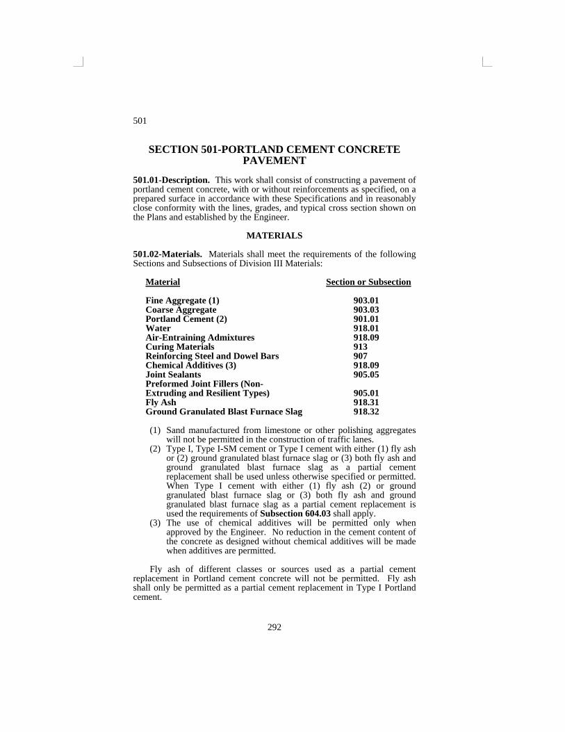
Material Section or Subsection Fine Aggregate (1) 903.01 Coarse Aggregate 903.03 Portland Cement (2) 901.01 Water 918.01 Air-Entraining Admixtures 918.09 Curing Materials 913 Reinforcing Steel and Dowel Bars 907 Chemical Additives (3) 918.09 Joint Sealants 905.05 Preformed Joint Fillers (Non- Extruding and Resilient Types) 905.01 Fly Ash 918.31 Ground Granulated Blast Furnace Slag 918.32 (1) Sand manufactured from limestone or other polishing aggregates
will not be permitted in the construction of traffic lanes. (2) Type I, Type I-SM cement or Type I cement with either (1) fly ash
or (2) ground granulated blast furnace slag or (3) both fly ash and ground granulated blast furnace slag as a partial cement replacement shall be used unless otherwise specified or permitted. When Type I cement with either (1) fly ash (2) or ground granulated blast furnace slag or (3) both fly ash and ground granulated blast furnace slag as a partial cement replacement is used the requirements of Subsection 604.03 shall apply.
(3) The use of chemical additives will be permitted only when approved by the Engineer. No reduction in the cement content of the concrete as designed without chemical additives will be made when additives are permitted.
Fly ash of different classes or sources used as a partial cement
replacement in Portland cement concrete will not be permitted. Fly ash shall only be permitted as a partial cement replacement in Type I Portland cement.
501
293
Ground granulated blast furnace slag of different grades or sources used as a partial cement replacement in Portland cement concrete will not be permitted. Ground granulated blast furnace slag will only be permitted as a partial cement replacement in Type 1 Portland cement.
Both fly ash and ground granulated blast furnace slag may be used as a partial cement replacement on the same project. When Type I-SM cement is used on a project, fly ash or ground granulated blast furnace slag as a partial cement replacement will not be permitted
Portland cement concrete with fly ash as a partial cement replacement shall not be produced until the concrete supplier furnishes the following information to the Engineer:
1. Copies of the results of all tests performed by the fly ash producer
within the previous 30 days on shipments to the concrete supplier showing: Fineness (percent retained on No. 325(45µm) sieve) LOI(loss on ignition) Specific gravity Soundness(autoclave expansion) Moisture content Pozzolantic activity, 7 day cement
2. A notarized certification from the fly ash producer stating that the fly ash meets the Departments specifications.
Portland cement concrete with ground granulated blast furnace slag as
a partial cement replacement shall not be produced until the concrete supplier furnishes the following information to the Engineer:
1. Copies of the results of all tests performed by the ground
granulated blast furnace slag producer within the previous 30 days on shipments to the concrete supplier showing:
Fineness(percent retained on the No. 325(45µm) sieve.) Air content of slag mortar Individual sample slag activity index (percent) Average of last five consecutive samples, slag activity index (percent) Specific gravity Sulfide sulfur(S)(percent) Sulfate ion reported as SO3 (percent) Total alkalie S(Na2O+0.658 K2O) Compressive strength (28 day)
2. A notarized certification from the ground granulated blast furnace slag producer stating that the slag meets the Department’s specifications.
501.03-Proportioning and Quality Assurance of Concrete. A. Proportioning :
501
294
The Contractor shall submit the proposed concrete design to the Engineer for approval. The design shall be determined using saturated surface dry aggregate weights and shall be verified by the use of trial batches meeting the requirements of these specifications. The concrete design shall be prepared by a TDOT certified Class 3 concrete plant technician, or by an approved independent testing laboratory under the direction of a registered professional civil Engineer, licensed by the State of Tennessee. The concrete plant technician or the Civil Engineer shall certify that the information contained on the design is correct and is the result of information gained from the trial batches. Trial batches for design, including admixtures in the proper proportion, shall be built no more than 90 days prior to the design submittal. All cost of concrete design, preparation and submittal shall be the responsibility of the Contractor.
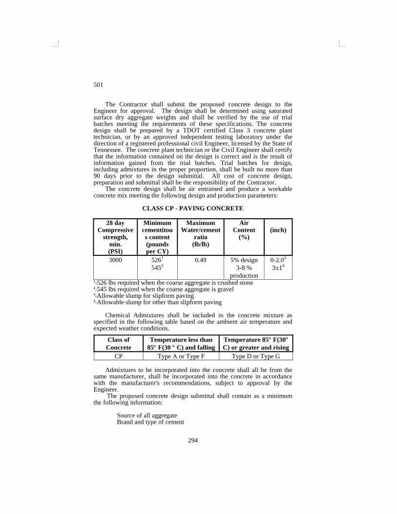
The concrete design shall be air entrained and produce a workable concrete mix meeting the following design and production parameters:
CLASS CP - PAVING CONCRETE
28 day Compressive
strength, min. (PSI)
Minimum cementitous content (pounds per CY)
Maximum Water/cement
ratio (lb/lb)
Air Content
(%)
(inch)
3000 5261
5452 0.49 5% design
3-8 % production
0-2.03
3±14
1-526 lbs required when the coarse aggregate is crushed stone 2-545 lbs required when the coarse aggregate is gravel 3-Allowable slump for slipform paving 4-Allowable slump for other than slipform paving
Chemical Admixtures shall be included in the concrete mixture as specified in the following table based on the ambient air temperature and expected weather conditions.
Admixtures to be incorporated into the concrete shall all be from the
same manufacturer, shall be incorporated into the concrete in accordance with the manufacturer's recommendations, subject to approval by the Engineer.
The proposed concrete design submittal shall contain as a minimum the following information:
Source of all aggregate Brand and type of cement
Class of Concrete
Temperature less than 85° F(30 ° C) and falling
Temperature 85° F(30° C) or greater and rising
CP Type A or Type F Type D or Type G
501
295
Source and class of fly ash (if used) Source and grade of ground granulated blast furnace slag (if used) Specific gravity of cement Specific gravity of fly ash (if used) Specific gravity of ground granulated blast furnace slag (if used) Admixtures (if used) Gradation of aggregates Specific gravities of aggregates (saturated surface dry) Air content (if air entrainment is used) Percentage of fine aggregate of the total aggregate (by volume) Slump Weight per cubic yard(m3) Yield Temperature of plastic concrete Water/cement ratio lb./lb.(kg/kg) 14 day compressive strength [minimum of 3 x-6in. x12in.(150 x
300 mm) cylinders] 28 day compressive strength [minimum of 3 x-6in. x12in.(150mm
x 300mm) cylinders] Weight of each material required to produce a yd3(m3) of concrete
In lieu of the above mix design submittal, the Contractor may submit
for approval to use an existing design (Contractor or Department prepared) approved by the Department within the current calendar year. The approval of this concrete design submittal will not relieve the Contractor of the responsibility of providing concrete meeting the requirements of these specifications. A temporary mix design may be issued if the 7 day compressive strengths exceed the required 28 day strengths.
If materials from sources other than those shown on the approved concrete design are to be used, the Contractor must submit and obtain approval of a concrete design showing these sources. No concrete shall be accepted with materials that are not shown on an approved concrete design.
In addition to the option to use Type I-SM cement, the contractor may have the option to replace a portion of Type I cement in Portland cement concrete, up to a maximum specified herein, with fly ash and/or ground granulated blast furnace slag. It is the Contractors responsibility, if he chooses to use fly ash and/or ground granulated blast furnace slag as a partial cement replacement, to provide Portland cement concrete of the design strengths specified in all applicable special provisions, on the plans, or in the standard specifications. Type I-SM cement or Type I cement with fly ash or ground granulated blast furnace slag as a partial cement replacement will not be used in concrete when high early strength is specified. When the Contractor elects to replace a portion of Type I cement with fly ash and/or ground granulated blast furnace slag, the following requirements must be verified prior to producing any Portland cement concrete:
1. Fly ash or ground granulated blast furnace slag shall be stored in silos separate from each other and separate from the Type I cement.
501
296
2. The fly ash or ground granulated blast furnace slag is to be added to the concrete by methods and equipment approved by the Engineer, capable of uniformly distributing the materials throughout the mix.
3. The fly ash or ground granulated blast furnace slag may be weighed cumulatively in the weigh hopper with the cement, provided the cement is added first. The temperature of the fly ash or the ground granulated blast furnace slag is not to exceed 160° F(71° C) at the time of introduction to the mix.
4. The mix shall be closely monitored to maintain a consistent air content between 3%and 8%.
Additional testing may be required to verify desired properties of
Portland cement concrete with fly ash or ground granulated blast furnace slag. Additional compensation for the expense and/or lost production due to the additional testing will not be allowed the Contractor. The following are examples of additional testing that may be required:
1. Additional air test as felt necessary by the Engineer to monitor the
entrained air due to fluctuations in LOI and fineness of the fly ash or ground granulated blast furnace slag material.
2. Additional compressive test specimens may be needed to determine strengths for form removal due to the slowed strength development inherent with fly ash or ground granulated blast furnace slag concrete.
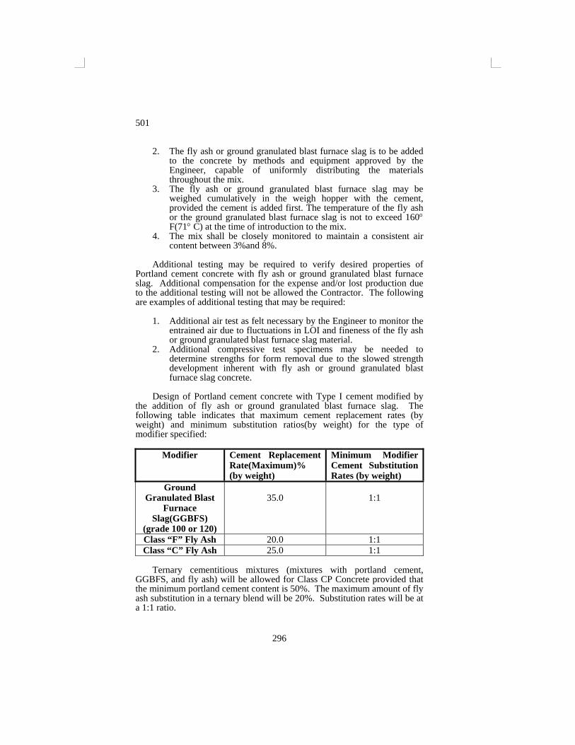
Design of Portland cement concrete with Type I cement modified by
the addition of fly ash or ground granulated blast furnace slag. The following table indicates that maximum cement replacement rates (by weight) and minimum substitution ratios(by weight) for the type of modifier specified:
Modifier Cement Replacement
Rate(Maximum)% (by weight)
Minimum Modifier Cement Substitution Rates (by weight)
Ground Granulated Blast
Furnace Slag(GGBFS)
(grade 100 or 120)
35.0
1:1
Class “F” Fly Ash 20.0 1:1 Class “C” Fly Ash 25.0 1:1
Ternary cementitious mixtures (mixtures with portland cement,
GGBFS, and fly ash) will be allowed for Class CP Concrete provided that the minimum portland cement content is 50%. The maximum amount of fly ash substitution in a ternary blend will be 20%. Substitution rates will be at a 1:1 ratio.
501
297
The Contractor shall submit a mix design with fly ash and/or ground granulated blast furnace slag as a partial replacement for Type I Portland cement in Portland cement concrete for the Department’s review and approval together with the following information, as a minimum, furnished by an approved independent testing laboratory:
1. Certified results of compressive strength test at ages 7, 14 and 28
days conducted in accordance with ASTM C 39. 2. Test for slump, entrained air content unit weight and yield conducted
in accordance with C-138, C-143, C-173 and C-231 as applicable.
Any request for a change in source of materials or admixtures from the original mix design must be made in writing to the Regional Materials and Tests Engineer explaining the necessity for the change and must be accompanied by a new mix design in accordance with the above provisions. No concrete shall be placed until the new design is approved.
When requested by the Contractor and approved by the Engineer, Class A Concrete for structures, as provided for under Section 604 and herein modified, will be permitted for use in variable width sections, ramps, and on projects containing 10,000 yd2(m2) of concrete pavement or less. The slumpshall be modified to be a maximum of 3 in.(75 mm) and the compressive strength of cylindrical specimens molded, cured and tested in an approved laboratory shall be not less than 3,000 psi(20.7 MPa) in 28 days. No additional payment will be made to the Contractor for increased costs due to the use of the above mixture.
The mix proportions approved by the Department shall govern during the progress of the work, except the Contractor shall make the following adjustments with the approval of the Engineer:
(a) If the cement content of the concrete varies by more than 2% from the designated value, as determined by AASHTO T 121, the proportions will be so adjusted as to maintain a cement content which does not vary more than 2% from the designated value.
(b) If it is found impossible to obtain concrete of the desired plasticity and workability with the proportions originally designed, changes will be made in aggregate weights as required, provided that in no case shall the cement content originally designated be changed except as provided in paragraphs (c), (d) and (e).
(c) If it is found impossible to produce concrete having the required consistency without exceeding the maximum allowable water-cement ratio specified, the cement content shall be increased so that the maximum allowable water-cement ratio will not be exceeded.
(d) If for any reason the concrete must be placed by hand methods and the water-cement ratio established for the vibrated concrete cannot be maintained, the mix proportions shall be adjusted for placement by hand methods and the cement proportion increased by 38 lbs per cubic yard(22 kgs per m3), or more if necessary in order to maintain the water-cement ratio established for the vibrated
501
298
concrete. No additional payment will be made to the Contractor for the cost of the additional cement.
(e) Change the mix proportions because of a change in the character or source of materials.
(f) Change the mix proportions or mixing procedure in order to maintain the air content within the specified limits.
(g) Change the mix proportions made necessary by the use of retarders or other chemical additives that may be required or approved.
B. Quality Control and Acceptance of Concrete:
It shall be the responsibility of the Contractor to determine and measure the batch quantities of all ingredients (including all water and any specified or approved admixtures) for all concrete produced for the project and to mix, deliver and place the concrete so that the concrete meets the requirements of these specifications. The minimum size of a batch shall be 2.5 cubic yards(2.0 m3). Sampling, testing and inspection for process control of the concrete at the concrete plant shall be performed by a TDOT Class 2 or higher concrete plant technician certified by the Department. This technician must be present at the concrete plant during all batching operations for the project and his primary responsibility during production shall be process control. Sampling, testing and inspection for process control of the concrete at the placement site shall be performed by a concrete technician that holds a TDOT Class 1, ACI Class 1, or higher certification. A technician shall be present at each placement site during all concrete placement. All necessary equipment required for process control shall be furnished by the Contractor and shall be at the plant and at the placement site at all times during concrete placement. Process control shall include, but not be limited to, the following tests and inspections:
1. Test to determine aggregate gradations (AASHTO T 27 with
AASHTO T 11 when required). 2. Frequent inspections of the stockpile to ascertain that stockpiles
are being maintained in an uncontaminated and unsegregated manner. A current aggregate quality report shall be kept at the plant.
3. Calibration of weighing systems, water meters and admixture dispensing systems prior to starting production.
4. Assurance of accurate weighing of the aggregates and cement, the proper metering of water and admixtures and the quality of water.
5. Assurance that mixing equipment is in proper working condition and the proper mixing speeds and revolutions are controlled as required by the specifications and the Materials and Tests Circular Letter File book.
6. Adjustment of mix proportions due to moisture content of both coarse and fine aggregates (moisture determination to be in accordance with AASHTO T 255).
7. Slump (AASHTO T 119) and Air Test (AASHTO T 152). 8. Yield test (AASHTO T 121) (When yield varies more than ±2%
from that shown on the design. All batching operations shall cease
501
299
until the problem has been identified and corrected or a new concrete design has been obtained.
9. All cylinders, including 28 day acceptance test cylinders, for compression tests in accordance with AASHTO T 22, except those required for independent assurance sampling and testing.
10. Tests for concrete and ambient air temperatures. 11. A report furnished daily to the Engineer showing all pertinent
information (Date, Contract and Project, Item number(s), batch weights, moisture corrections, admixtures, slump, air content, temperatures, etc.). A sample daily report will be given to the Contractor as an example.
12. A concrete delivery ticket must accompany each load to the placement site. The ticket shall at a minimum include the following:
Date Contract number County Class of concrete Concrete design number Number of cubic yards Load number Truck number Maximum water allowed by design Total water added at the plant Maximum water allowed to be added on the project Actual water added on project Number of revolutions at mixing speed at plant Number of revolutions at mixing speed at project Time loaded Time discharged Actual and target batch weights of each component including
each aggregate, chemical admixture and mineral admixture used.
The Contractor shall develop for approval of the Engineer and maintain
at the plant written procedures for sampling, testing and inspection of the concrete. The Contractor shall keep a record of all tests and inspections performed at the plant site and placement site, and this documentation, together with a certification by the Contractor that the concrete incorporated in the work meets the requirements of the specifications, shall be delivered to the Engineer upon completion of the project for inclusion in the project records. Records shall be kept current and shall be made available to the Engineer for review at any time.
It shall be the responsibility of the Contractor to properly make, cure and transport all 28 day acceptance cylinders in accordance with AASHTO T 23 to the Central Laboratory in Nashville for testing. However, the Department will furnish transportation for the cylinders to the Central Laboratory if the Contractor requests, providing the Contractor delivers the cylinders to the Regional Laboratory or other designated pickup sites
501
300
established by the Regional Materials Engineer. All early break cylinders (14 day, etc.) must be delivered to the Regional laboratory or other established satellite laboratories for tests.
A TDOT certified class 2 or higher concrete technician, whose duty is process control, shall be at the ready-mix plant during all batching operations. A TDOT or ACI certified class 1 or higher technician is not required to be at the placement site during all small quantity placing operations but is required to perform one complete set of tests during the life of the project. A delivery ticket must accompany each load delivered to the job site.
Batch weights shall be corrected to compensate for any surface moisture on the aggregate at the time of use. The Contractor may elect to withhold some of the water from the mix at the plant provided the delivery ticket indicates the amount of water withheld. If a portion of the water is withheld at the plant, additional water may be added at the work site provided the design water/cement ratio of the mix is not exceeded.
EQUIPMENT 501.04-Equipment. Equipment and tools necessary for handling materials and performing all parts of the Work shall be approved by the Engineer as to design, capacity, and mechanical condition. The equipment shall be at the job site sufficiently ahead of the start of construction operations to be examined thoroughly and approved.
(A) Batching Plant and Equipment.
1. General.
The batching plant shall include bins, weighing hoppers, and scales. If cement is used in bulk, a bin, hopper, and separate scale for cement shall be included. The Contractor shall provide adequate means for cement cut off checks. The weighing hoppers shall be properly sealed and vented to preclude dusting during operation. The bulk cement storage bin or hopper shall be provided with adequate means for sampling the cement in storage.
2. Bins and Hoppers.
Bins with adequate separate compartments for fine
aggregates, each size of coarse aggregate, and cement shall be provided in the batching plant. Each compartment shall discharge efficiently and freely into the weighing hopper. Means of control shall be provided so that as the quantity desired in the weighing hopper is being approached, the material may be added slowly and shut off with precision. A port or other opening shall be provided for removing an overload of any one of the several materials from the hopper. Weighing hoppers shall be constructed so as to eliminate
501
301
accumulations of tare materials and to discharge fully without jarring the scales. Partitions between compartments, both in bins and in hoppers, shall be ample to prevent spilling under any working conditions.
3. Scales.
The scales for weighing aggregates, cement and
pozzolans shall be of the beam type, springless, dial type or load cell type. Scales shall be accurate within 0.5% throughout the range of use. Scale dial faces or digital readouts are to be graduated such that loads of 0.1% or less of scale capacity are indicated.
When beam type scales are used, an indicator such as a "tell-tale" dial shall be provided to inform the operator that the required load in the weighing hopper is being approached. The "tell-tale" device on weighing beams shall indicate the critical position clearly. Poises shall be designed so that they cannot be easily removed from the beam and can be held firmly in place. The weigh beams and "tell-tale" device shall be in full view of the operator while charging the hopper, and he shall have convenient access to all controls.
Scales shall be inspected and checked as often as the Engineer may deem necessary to assure their continued accuracy. The Contractor shall have available not less than 10 standard 50 lbs(25 kgs) weights meeting the requirements of the U. S. Bureau of Standards for calibrating and testing weighing equipment.
(B) Mixers.
1. General.
Concrete may be mixed at the site of construction or at a
central point or wholly or in part in truck mixers. Each mixer shall have attached in a prominent place a manufacturer's plate showing the capacity of the drum, in terms of mixing and agitating capacity, and the speed of rotation of the mixing drum or blades for both mixing and agitation.
Mixers shall be capable of combining the aggregates, cement, additives when specified, and water into a thoroughly mixed and uniform mass within the specified mixing period. They shall have a minimum capacity sufficient to comply with minimum production requirements.
Mixers shall be equipped with an approved device for accurately measuring water within a range of error of not more than 1%. The amount of water used in each batch shall be shown by an indicator that is accurately calibrated and easily read.
501
302
Central plant mixers and mixers at the site of construction shall be equipped with an approved batch meter and timing device which will automatically lock the discharge lever during the full time of mixing and release it at the end of the mixing period. This device shall be equipped with a bell or other suitable warning device that will give a clearly audible signal each time the lock is released. In case of failure of the timing device, the mixer may be used for the balance of the day while it is being repaired, providing the Contractor furnishes a satisfactory means of determining the mixing time.
The pickup and throw-over blades in the drum or drums shall be repaired when the blade wear reaches the blade wear indicator or when holes are worn through the blades. The top of the blade wear indicator is to be placed at 90% of the total height of the radial part of the blade. The Contractor shall have available at the job site or central plant a copy of the manufacturer's design showing dimensions and arrangements of blades. The blade wear indicator is to be made of ¼ min. thick steel 2 in. wide and 6 in. long. They shall be located as shown in the Department of Transportation’s “Division of Materials and Test, circular D-9. All mixers shall have blade wear indicators.
2. Mixers at Site of Construction.
In addition to the above requirements, mixers at the site
of construction, unless otherwise stipulated, shall be of the boom and bucket type and shall be capable of discharging and distributing the mix without segregation on the prepared subgrade or sub-base.
3. Truck Mixers and Truck Agitators.
Truck mixers used for mixing and hauling concrete and
truck agitators used for hauling central-mixed concrete shall meet all the applicable requirements under 1. above, and in addition, the manufacturer's plate shall indicate the various uses for which the equipment is designed, the gross volume of the drum, and the minimum and maximum speed of rotation of the drum or blades for charging, mixing and agitating. Trucks equipped for mixing shall be equipped with an approved device for recording the number of revolutions of the drum or blades. Mixers or agitators used to mix and transport paving concrete shall be of the hydraulic drum lift type or other especially designed types which will discharge low slump concrete 1/2 to 1 1/2 ins(13 to 38 mm) at a satisfactory rate without segregation. Approved conventional or standard truck mixers or truck agitators may be used for mixing and hauling concrete under Section 604; for projects that contain 10,000 yd2 (m2) or less of concrete paving.
501
303
4. Nonagitator Trucks.
Bodies of nonagitator hauling equipment for concrete
shall be smooth, mortar-tight, metal containers, and shall be capable of discharging the concrete at a satisfactorily controlled rate without segregation. Covers shall be provided for protection of the concrete.
(c) Forms.
Straight side forms shall be made of metal having a thickness
of not less than 7/32 in.(5 mm) and shall be furnished in sections not less than 10 ft(3 m) in length. Forms shall have a depth at least equal to the prescribed edge thickness of the concrete, without horizontal joint, and a base width equal to not less than the depth of the forms. Flexible or curved forms of wood or metal and of proper radius shall be used for curves of 100-ft(30 m) radius or less. Flexible or curved forms shall be of a design acceptable to the Engineer. Forms shall be provided with adequate devices for secure setting so that when in place they will withstand, without visible spring or settlement, the impact and vibration of the consolidating and finishing equipment. Flange braces shall extend outward on the base not less than 2/3 the height of the form. The top face of the form shall not vary from a true plane more than 1/8 in. in 10 ft(3 mm in 3 m), and the face of the form shall not vary more than 1/4 in(6 mm). The forms shall contain provisions for locking the ends of abutting form sections together tightly, and for secure setting. Metal pins shall be of proper size and length to hold the forms rigidly and securely in place.
Built-up forms shall not be used except where the total area of pavement of any specified thickness on the project is less than 10,000 yards.y.(m2). Build-up forms shall have a minimum base width of 8 in.(200 mm).
Forms with battered top surfaces, and bent, twisted, or broken forms shall be removed from the Work. Repaired forms shall not be used until inspected and approved.
The supply of forms, provided and maintained in satisfactory condition, shall not be less than that required for a full day's run.
(d) Spreading and Finishing Equipment.
Equipment shall include a paving machine designed to
uniformly vibrate and finish the concrete full width and to its final grade.
1. Vibrators.
Vibrators for full-width and full-depth vibration of
concrete paving slabs shall be multiple spuds or other types
501
304
approved by the Engineer. They may be attached to the spreader or the finishing machine, or may be mounted on a separate carriage. The frequency of the vibrators shall be that recommended by the manufacturer, subject to approval of the Engineer. The Contractor shall furnish the Engineer the manufacturer's recommendations for installing and operating vibrators.
2. Longitudinal Floats.
The mechanical longitudinal float shall be of a design
approved by the Engineer, and shall be in good working condition. It shall be so constructed as to provide for accurate adjustment to the required crown.
3. Bridges.
The Contractor shall furnish a minimum of 2 individual
work bridges.
4. Finishing Straightedge.
Straightedges, not less than two, with handles at least 3 ft(1 m) longer than 1/2 the width of the slab, shall be constructed of light metal; shall be not less than 10 ft(3 m) long; and shall be maintained clean and straight.
5. Straightedge Templates.
Straightedge templates, not less than 2, shall be provided
for testing the completed surface. They may be of wood or metal; shall not be less than 12 ft(3.6 m) long; and shall be maintained clean, straight, and free from warp.
6. Water Supply Equipment.
Water supply equipment shall include pumps, or tanks
mounted on trucks, of adequate capacity to furnish more than sufficient water to accommodate this construction and at the required and necessary pressure. A pipe line appropriate to the requirements of the construction may be used.
7. Small Tools.
Small tools, such as edgers, trowels, hand floats, brushes,
etc., shall be such as will produce the results required.
8. Special Equipment and Tools.
501
305
Equipment and tools necessary for the Construction of special features as indicated on the Plans shall be such as will produce the results required.
9. Transverse Grooving Equipment.
Mechanical Transverse grooving equipment shall consist
of a steel tine comb with a minimum width of 6 ft(1.8 m), a vibrating beam roller, or other approved devices.
10. Concrete Saw.
When sawed joints are elected or specified, the
Contractor shall provide sawing equipment adequate in number of units and power to complete the sawing to the required dimensions and at the required rate. The saws shall be equipped with water-cooled diamond edge blades. Saws used for sawing longitudinal joints shall be equipped with guides to assure proper alignment of the joints.
The Contractor shall provide at least one standby saw in good working order. An ample supply of saw blades shall be maintained at the site of the Work at all times during sawing operations. The Contractor shall provide adequate artificial lighting facilities for night sawing. All of this equipment shall be on the job both before and continuously during concrete placement.
11. Slip-form Paver.
The slip-form paver shall be an approved self-propelled
type, equipped with a crawler type track of sufficient area to prevent track slippage under load. Length of ground contact per track and arrangement of track units shall be adequate to insure the established straightedge tolerance. When this method of construction is used, all provisions and requirements of these Specifications, which are not in conflict, shall be applicable.
Pavement alignment shall be controlled by means of an electronic sensing device in continuous contact with a sensing guide. The Contractor shall furnish equipment with electronic controls for the vertical adjustment of the paver strike-off and finishing components. Electronic controls, sensing devices, and sensing guides shall be furnished, installed, and maintained at the expense of the Contractor.
CONSTRUCTION REQUIREMENTS
501.05-Subgrade Preparation. Subgrade preparation shall be performed as provided for under Section 207 of these Specifications.
501
306
501.06-Construction of Base. Base shall be constructed in accordance with the provisions of the applicable Section of Division II, Part 2 Bases and Subgrade Treatments.
The Contractor shall be responsible for constructing the base to such grade tolerances as will insure the concrete pavement thickness required.
Base shall be completed not less than 500 ft(150 m) in advance of paving.
The base grading machine and slip-form paver shall be equipped with automatic line (guidance) and grade controls. 501.07-Setting Forms.
(a) Base Support.
The foundation under the forms shall be firm and true to grade so that each form, when set, will be firmly in contact for its whole length and at the specified grade. Any grade at the form line found below established grade shall be filled to grade with suitable material in lifts of 1/2 in.(13 mm) or less for a distance of 18 in.(450 mm) on each side of the base of the form, and thoroughly compacted. Any grade at the form line found above grade shall be corrected by tamping or by cutting as necessary. Pedestals of earth or other material upon which to rest the forms to bring them to grade will not be permitted.
(b) Form Setting.
Forms shall be set and approved for the placing of concrete a
minimum of 500 ft(150 m) in advance of the point where concrete is being placed. This distance may be reduced as approved by the Engineer when a shorter distance is justified by prevailing conditions. After the forms have been set to correct grade, the material supporting the forms shall be thoroughly tamped, mechanically, or by hand, at both the inside and outside edges of the base of the forms. Forms shall be staked into place with not less than three pins for each 10 ft(3 m) section. A pin shall be placed at each side of every joint. Form sections shall be tightly locked and free from play or movement in any direction. The forms shall not deviate from true line by more than 1/4 in.(6 mm) at any point. Forms that settle or spring under the spreading and finishing equipment shall be reset or removed as directed. The top and face of forms shall be cleaned and oiled prior to the placing of concrete.
(c) Grade and Alignment.
The alignment and grade elevations of the forms shall be
checked and corrections made by the Contractor immediately before placing the concrete. When any form has been disturbed or
501
307
any grade has become unstable, the form shall be reset and rechecked.
501.08-Conditioning of Base. The grade shall be checked and corrected immediately ahead of the placing of the concrete. Final section shall be attained by means of an approved machine with automatic grade control. If the slip-form method of paving is used, the base shall be placed, compacted and finished to the proper grade to a width beyond the pavement limits sufficient to support all paving equipment.
High areas shall be removed and replaced. Low areas may be filled with base material and compacted to correspond with the surrounding areas, except that low areas in cement treated bases, and bituminous bases shall be filled with concrete integral with the pavement. Low area in lean concrete base shall be repaired as directed by the Engineer.
The base shall have been previously wetted, and shall be in a moist condition at the time of placing concrete. If it subsequently becomes dry previous to the actual placing of the concrete, it shall be sprinkled, but the formation of pools of water shall be avoided. The base shall not be muddy or soft. 501.09-Handling, Measuring and Batching Material. The batch plant site, layout, equipment and provisions for transporting material shall be such as to assure a continuous supply of material to the work. Aggregate stockpiles shall be built and maintained in accordance with Subsection 903.20. A concrete delivery ticket must accompany each load to the placement site and shall include the following information at a minimum:
Date Contract number County Class of concrete Concrete design number Number of cubic yards Load number Truck number Maximum water allowed by design Total water added at the plant Maximum water allowed to be added on the project Actual water added on project Number of revolutions at mixing speed at the plant Number of revolutions at mixing speed at the project Time loaded Time discharged Actual and target batch weights of each component including each aggregate, chemical admixture and cementitious material used.
Aggregates shall be handled from stockpiles or other sources to the batching plant in such manner as to maintain a uniform grading of the material. Aggregates that have become segregated, or mixed with earth or foreign material, shall not be used. All aggregates produced or handled by
501
308
hydraulic methods, and washed aggregates, shall be stockpiled or binned for draining at least 12 hours before being batched. Rail shipment requiring more than 12 hours will be accepted as adequate binning only if the car bodies permit free drainage. In case the aggregates contain high or non-uniform moisture content, storage or stockpile periods in excess of 12 hours may be required by the Engineer. The Engineer may require sprinkling of aggregate that has dried to the extent that it absorbs mixing water.
The fine aggregate and each size of coarse aggregate shall be separately weighed into the hopper or hoppers in the respective amounts set by the Engineer. The course aggregates shall meet the grading requirements for Size No. 467(37.5 to 4.75 mm), shown in Table 1 in Subsection 903.22 or a blend of Size No. 4(37.5 to 19.0 mm) and Size No. 67(19.0 to 4.75 mm) that meet the required gradation for Size No. 467(37.5 to 4.75 mm), Table 1 as described in Subsection 903.22. Cement shall be measured by weight. Separate scales and hoppers shall be used for weighing the cement. The scales shall be equipped with a device to indicate positively the complete discharge of the batch of cement into the batch box or container.
Batching plants equipped to proportion aggregates and bulk cement by weight by means of automatic and interlocked proportioning devices of approved type may be used.
When the quantity of cement being weighed exceeds 30% of the full capacity of the scale, the quantity of cement or the quantity of cement plus pozzolan, when used, shall be within 1% of the required weight. When weighing less than 30% of the full scale capacity, the quantity of cement or the quantity of cement plus pozzolan, when used, shall be not less than the required amount nor more than 4% in excess. Aggregates shall be weighed within a tolerance of 1.5% of the required weight.
When mixing is at the site of the Work, aggregates shall be transported from the batching plant to the mixer in batch boxes, vehicle bodies, or other containers of adequate capacity and construction to properly carry the volume required. Partitions separating batches shall be adequate and effective to prevent spilling from one compartment to another while in transit or being dumped. When bulk cement is used, the Contractor shall use a suitable method of handling the cement, from weighing hopper to transporting container, for transportation to the mixer, with chute, boot, or other approved device, to prevent loss of cement and to provide positive assurance of the actual presence in each batch of the entire amount specified.
Bulk cement shall be transported to the mixer in weatherproof compartments carrying the full amount of cement required for the batch. Cement in original shipping packages may be transported on top of the aggregates, each batch containing the proportion required by the job-mix.
Batches shall be delivered to the mixer separate and intact. Each batch shall be dumped into the mixer without loss of any material, and when more than one batch is carried on the truck, without spilling of material from one batch compartment to another.
Water may be measured either by volume or by weight. The accuracy of measuring the water shall be within a range of error of not over 1 per cent. Unless otherwise permitted, calibrated tanks for measuring water
501
309
shall include an auxiliary tank from which the measuring tank shall be filled. The measuring tank shall be equipped with an outside tap and valve to provide for checking the setting unless other means are provided for readily and accurately determining the amount of water in the tank. The volume of the auxiliary tank shall be at least equal to that of the measuring tank.
The use of chemical additives shall be as prescribed under Subsection 501.02, and they shall be added to the mix using the methods and in the manner recommended by the manufacturer of the additive, subject to approval by the Engineer.
Air-entraining agents shall be added to the mix by an approved procedure and by the use of an approved dispenser to assure an accurate proportioning of the agent.
All admixtures shall be measured with an accuracy of plus or minus 3%. 501.10-Mixing Concrete. The concrete may be mixed in a concrete paver at the site of the Work, in a central-mix plant, or in truck mixers. The mixer shall be of an approved type and capacity, and shall comply with the applicable requirements of Subsection 501.04(b). Mixers shall be cleaned at suitable intervals.
The batch shall be so charged into the drum that a portion of the mixing water shall enter in advance of the cement and aggregates. Mixing time shall be measured from the time all materials except water are in the drum. The flow of water shall be uniform, and all water shall be in the drum by the end of the first 15 seconds of the mixing period. The throat of the drum shall be kept free of such accumulations as may restrict the flow of materials into the drum.
When mixed in a concrete paver at the site of the Work or in a central mixing plant, the mixing time shall not be less than 60 seconds nor more than 90 seconds. Mixing time ends when the discharge chute opens. Transfer time in multiple drum mixers shall be included in the mixing time. The contents of an individual mixer drum shall be removed before a succeeding batch is emptied therein.
The mixer shall be operated at the drum speed recommended by the manufacturer. Any concrete mixed less than the specified time shall be discarded and disposed of by the Contractor at his expense. Mixers for central-mix plants shall not be operated at a capacity greater than the manufacturer's guaranteed mixing capacity. Concrete pavers for mixing at the site of the work shall not be operated at a capacity greater than the mixer's rated capacity in cubic feet(m3), as shown on the manufacturer's standard rating plate on the mixer, except that an overload up to 10% above the rated capacity may be permitted provided concrete test data for strength, segregation, and uniform consistency are satisfactory, and provided no spillage of concrete takes place.
Mixed concrete from the central mixing plant shall be transported in truck mixers, truck agitators or nonagitating trucks having special bodies. Truck mixers and truck agitators used to transport concrete from a central mixing plant and truck mixers used to mix concrete in transit from a central batching plant shall meet all applicable requirements of Subsection
501
310
501.04(b) 3, and in addition, the mixing speed and agitating speed shall be those recommended by the manufacturer of the mixer and the total revolutions at mixing speed shall not be less than 70 nor more than 100. Truck mixers and truck agitators shall be operated within the capacity recommended by the manufacturer. When truck mixers are used on hauls in excess of 1 hour, the cement shall be added at the site of the work and mixing performed as specified under this Subsection.
The time elapsing from the time water is added to the mix until the concrete is deposited in place at the site of the Work shall not exceed 30 minutes when the concrete is hauled in non-agitating trucks, nor 60 minutes when hauled in truck mixers or truck agitators.
Retempering concrete by adding water or by other means will not be permitted; however, a portion of the mixing water may be withheld from transit mixers and added at the work site provided the delivery ticket indicates the amount of water withheld. The batch shall be mixed for 30 revolutions at mixing speed after adding the water. Water cannot be added to a partial load of concrete mix. Concrete that is not within the specified slump limits at time of placement shall not be used. Admixtures for increasing the workability or for accelerating the set will be used only when provided for in the Contract, or permitted by the Engineer. The addition of admixtures to the mix shall be in accordance with the provisions of Subsection 501.09.
Tests for air content shall be made on samples of fresh concrete when and as directed. The air content shall be that specified under Subsection 501.03 of these Specifications and shall be determined in accordance with AASHTO T 152 or T 196. 501.11-Limitations of Mixing. Mixing of concrete shall be discontinued in time to allow finishing to be completed in daylight hours, unless an adequate and approved artificial lighting system is provided and operated.
Unless authorized in writing by the Engineer, mixing and concreting operations shall be discontinued when a descending air temperature in the shade and away from artificial heat reaches 40° F(4° C), and not resumed until an ascending air temperature in the shade and away from artificial heat reaches 35° F(2° C).
When concreting at temperatures above 35° F(2° C), the aggregates or water shall be heated or cooled if necessary prior to being placed in the mixer so that the temperature of the resultant mixture will be not less than 50° F(10° C) nor more than 90° F(32° C) at the time of placement. If heating is required, the apparatus used shall heat the mass uniformly and shall be so arranged as to preclude the possible occurrence of overheated areas which might injure the concrete. No frozen aggregates shall be used in the concrete.
When concreting is authorized at temperatures 35° F(2° C) or less, the Engineer will require the water or the aggregates or both to be heated to not less than 70° F (21° C) nor more than 150° F(65° C). The temperature of the mixed, heated concrete shall be not less than 60° F(15° C) nor more than 100° F(38° C) at the time of placing on the road.
501
311
501.12-Placing Concrete. The concrete shall be unloaded into an approved spreading device, or deposited on the base, and mechanically spread in such manner as to prevent segregation of the materials. When central or transit mixed concrete is used, it shall be deposited in an approved spreader. As deposited, the mixture shall be placed where it will require as little rehandling as possible. The mechanical spreader will not be required on areas too small to accommodate the paving equipment, projects that contain 10,000 yd2(m2) or less of concrete paving, nor on variable width sections and ramps. Placing shall be continuous between transverse joints without the use of intermediate bulkheads. No concrete shall be placed on frozen grade.
Necessary hand spreading shall be done with shovels, or other approved tools. Workmen shall not be allowed to walk in the freshly mixed concrete with boots or shoes coated with earth or other foreign substances.
Where concrete is to be placed adjoining a previously constructed lane of pavement and mechanical equipment will be operated upon the existing lane of pavement, that lane shall meet the requirements for opening to traffic stipulated in Subsection 501.22. If only finishing equipment is carried on the existing lane, paving in adjoining lanes may be permitted after seven days.
Concrete shall be thoroughly consolidated against and along the faces of all forms and along the full length and on both sides of all joint assemblies, by means of vibrators inserted in the concrete. Vibrators shall not be permitted to come in contact with a joint assembly, the grade, or a side form. In no case shall the vibrator be operated longer than 5 seconds in any 1 location.
The use of hand operated vibrators will only be permitted on projects that contain 10,000 yd2(m2) or less of concrete paving and on variable width sections. Vibrators mounted on a machine shall be operated only while the machine is in motion.
Concrete shall be deposited as near to expansion and contraction joints as possible without disturbing them, but shall not be dumped from the discharge bucket or hopper onto a joint assembly unless the hopper is well centered on the joint assembly.
Should any concrete materials fall on or be worked into the surface of a completed slab, they shall be removed immediately by approved methods.
When the slip-form method of concrete paving(without the use of-fixed forms) is used, the concrete shall be placed with an approved slip-form paver designed to spread, consolidate, screed and float-finish the freshly placed concrete in 1 complete pass of the machine in such manner that a minimum of hand finishing will be necessary to provide a dense and homogeneous pavement in conformance with the plans and specifications. The machine shall be equipped to vibrate the concrete for the full width and depth of the strip of pavement being placed. Such vibration shall be accomplished with equipment meeting the applicable requirements of Subsection 501.04(d) 1. The sliding forms shall be rigidly held together laterally to prevent spreading of the forms. The forms shall trail behind the paver for such a distance that no appreciable slumping of the concrete will occur and that necessary finishing can be accomplished while the concrete is still within the forms. Any edge slump of the pavement, exclusive of
501
312
edge rounding, in excess of 1/4 in.(6 mm) shall be corrected before the concrete has hardened.
The slip-form paver shall be operated with as nearly a continuous forward movement as possible and all operations of mixing, delivering and spreading concrete shall be coordinated so as to provide uniform progress with stopping and starting of the paver held to a minimum. If, for any reason, it is necessary to stop the forward movement of the paver, the vibratory and tamping elements shall also be stopped immediately. No tractive force shall be applied to the machine, except that which is controlled from the machine. Any slabs with random cracks, will be replaced before completion of paving operations. 501.13-Testing Concrete. All sampling and testing of materials shall be performed in conformance with the Department's Policies on Sampling and Testing Procedures. During the process of work if either the slump or air consistency tests give results outside the allowable specification range, no additional concrete will be placed until the slump and/or air content is brought within specification limits.
The 28 day compressive strength of the concrete in the construction shall be determined by tests made during the process of work as prescribed in Subsection 604.16. The method of making and curing test specimens will be in accordance with AASHTO T 23. The Contractor shall furnish the concrete necessary for the Engineer to conduct the field tests and shall provide a storage facility with watertight tanks of satisfactory size and number to accommodate the cylinder specimens. The Engineer at his discretion may allow concrete which fails to meet the strength specified to remain in place, but payment for this concrete will be made at a reduced price as provided in Subsection 604.32 to compensate the Department for the loss of strength. Any reduction in payment because of low strength will be in addition to any reduction in payment which may be made because of deficiencies in pavement thickness or rideability.
The thickness of the pavement will be determined from test cores drilled from each unit of pavement as prescribed in Subsection 501.24. 501.14-Strike-Off of Concrete and Placement of Reinforcement. Following the placing of the concrete, it shall be struck off to conform to the cross section shown on the Plans and to an elevation such that when the concrete is properly consolidated and finished, the surface of the pavement will be in reasonably close conformity with the elevation shown on the Plans or established by the Engineer. When reinforced concrete pavement is placed in two layers, the entire width of the bottom layer shall be struck off to such length and depth that the sheet of fabric or bar mat may be laid full length on the concrete in its final position without further manipulation. When steel fabric is indicated, it shall be placed in strips transversely with the roadway at the depth and with the lap shown on the Plans. The fabric shall extend to within 2 in.(50 mm) of the ends and sides of the slab. The reinforcement shall be placed directly upon the concrete, after which the top layer of the concrete shall be placed, struck off and screeded. Any portion of the bottom layer of concrete which has been placed more than 30 minutes without being covered with the top layer shall be removed and
501
313
replaced with freshly mixed concrete at the Contractor's expense. When reinforced concrete is placed in 1 layer, the reinforcement may be positioned in advance of concrete placement, or it may be placed after the concrete is spread by mechanical or vibratory means.
Reinforcing steel shall be free from dirt, oil, paint, grease, mill scale, and loose or thick rust which could impair bond of the steel with the concrete. 501.15-Joints. Joints shall be constructed of the type and dimensions and at the locations required by the Plans and in accordance with the provisions of these Specifications.
Longitudinal joints shall be perpendicular to the pavement surface and shall be along or parallel to the center-line of the pavement, unless otherwise specified. Transverse joints shall be straight, vertical to the pavement surface and shall be at the angle to the center-line of the pavement shown on the Plans.
Unless otherwise specified or directed, all contraction and construction joints shall be of the plain sawed groove type.
(a) Longitudinal Joints.
Deformed steel tie bars of specified length, size, spacing, and materials shall be placed across and perpendicular to the longitudinal joints. They shall be placed by approved mechanical equipment or rigidly secured by chairs or other approved supports to prevent displacement. When the slip-form method of paving is used, the tie bars shall be placed prior to vibration.
Proper installation of tiebars in existing hardened concrete will require pre-drilled holes into the existing concrete slab. The holes will be drilled to minimum depth of ½ the tie-bar length and 1/8 in. greater diameter than the tie-bar used for installation. All pre-drilled holes shall be thoroughly cleaned using a wire brush and compressed air. The epoxy or adhesive material used to secure the tiebar shall be capable of withstanding minimum average pull-out resistance of 12,000 lbs. or to a maximum slippage of 1/32 in. It will be up to the contractor to provide jacking equipment or other suitable means to test the tiebars to meet the minimum pull-out resistance to the satisfaction of the Department.
A representative test section of 15 tiebars or 2% of the total amount used on the project shall be tested to determine if the installation method is acceptable. The acceptance will be based on the pull-out data of this test section. More than 1 test section may be required if the methods and procedures of the contractor vary from the original procedure or there is reason to believe the installation is faulty.
All costs involved in the above procedure regarding tiebar installation will be included in the price bid for tiebar installation.
Longitudinal sawed joints shall be cut by means of approved concrete saws to the depth, width and line shown on the Plans, not
501
314
later than 10 days after placing concrete and before any equipment or vehicles are allowed on the pavement.
Immediately after sawing, all longitudinal contraction and construction joints shall be thoroughly cleaned of all residue by flushing with water under pressure.
(b) Transverse Expansion Joints.
Dowels shall be prepared and placed across transverse
expansion joints as indicated on the Plans. Dowels shall be held in position, parallel to the surface and
centerline of the slab, by an approved metal device that is left in the slab. Unless otherwise specified, dowels shall be painted with one coat of approved primer and shall be thoroughly coated with a thin film of oil or approved bond breaker. If oil is used it shall be applied after the paint has dried and immediately before placement. If corrosion resistant dowels are specified, the bond breaker for corrosion resistant dowels shall be as recommended by the coating manufacturer or as directed by the Engineer. One end of each dowel shall be covered with a close fitting, closed end metal or plastic sleeve, not less than 4 in.(100 mm) long, with a flange or other approved device to separate the end of the sleeve and the end of the dowel during the placing of the concrete so that a space of not less than the proposed thickness of the joint plus 1/4 in.(6 mm) will be provided for subsequent movement of the dowel in the sleeve. The type of sleeve to be used on the dowel bars shall meet the approval of the Engineer. Dowels shall have ends free from burrs and distortions. Wires of dowel baskets shall be cut prior to concrete placement.
Transverse expansion joints shall be of the kind and type shown on the Plans. When premolded joint filler is used, it shall be installed by the use of one of the alternate expansion joint and dowel assembly devices shown on the Plans, or other approved expansion joint assemblies may be used. The installing device shall have a length 1/2 in.(13 mm) less than the width of the slab. Assemblies shall be a rigid metal device capable of holding dowels and filler firmly in position during the entire construction operation and shall remain in place. The top of the filler shall be set below the surface of the proposed slab to accommodate the type sealant specified, as detailed on the Plans. When in position, the filler shall be perpendicular to the surface of the slab. The top edge of the filler shall be protected, while the concrete is being placed, by an approved metal channel cap. The assembly device may be designed with this cap self-contained.
(c) Transverse Contraction Joints.
Transverse contraction joints shall be placed at the intervals
specified and resulting in the desired shape. Formed contraction
501
315
joints shall not be used unless specified or required by the Engineer to control random cracking.
Load transfer dowels shall be placed at intervals and depths indicated on the Plans. Unless otherwise specified, dowels shall be painted with one coat of approved primer and shall be thoroughly coated with a thin film of oil or approved bond breaker. If oil is used it shall be applied after the paint has dried and immediately before placement. If corrosion resistant dowels are specified, the bond breaker for corrosion resistant dowels shall be as recommended by the coating manufacturer or as directed by the Engineer.
In lieu of using dowel assemblies at contraction joints, dowel bars may be placed in the full width of pavement by a mechanical device approved by the Engineer. The Contractor desiring to use a dowel implanting device must first demonstrate accurate dowel placement and pavement finish.
1. Sawing of the joints shall commence as soon as concrete has
hardened sufficiently to permit sawing without excessive raveling. Once started, the sawing operation shall be continuous until all transverse contraction joints are sawed. When necessary, the contractor shall provide for bad weather or nighttime operations. The sawing of any joint shall be omitted if a crack occurs at or near the joint location prior to the time of sawing. The sawing of a joint shall be discontinued when a crack develops ahead of the saw. In general, all joints shall be sawed in sequence.
All contraction joints in lanes adjacent to previously constructed lanes shall be sawed before uncontrolled cracking occurs. If extreme conditions exist which make it impractical to prevent erratic cracking by early sawing, a contraction joint groove shall be formed at intervals of every 3rd or 4th joint or as often as required prior to initial set of concrete as provided for under (c) 3, below. Immediately after sawing, the joints shall be thoroughly cleaned of all residue by flushing with water under pressure.
Sawing equipment shall be approved by the Engineer. Only lightweight sawing equipment will be permitted on the newly constructed pavement.(See Subsection 501.10(d)10. Gang saw units or similar heavy equipment may be used provided the equipment is operated from a bridge or platform supported independently of the pavement.
2. Formed contraction joints shall be formed during the placing
of the concrete. These joints shall be formed by placing inserts in the plastic concrete, at the angle to the centerline of the pavement indicated on the Plans and perpendicular to the surface. When the concrete has attained its initial set and after the joint has been carefully finished, the insert shall be removed. The groove so formed shall maintain its full width
501
316
and depth as shown on the Plans, and the pavement at the joint shall meet surface requirements.
(d) Transverse Construction Joints.
Transverse construction joints shall be constructed to provide
a uniform surface. The surface texture shall be provided as specified. (See Subsection 501.15(c) if needed) The joints shall be constructed when there is an interruption of more than 30 minutes in the concreting operations. No transverse joints shall be constructed within 10 ft.(3 m) of an expansion joint, contraction joint, or plane of weakness. If sufficient concrete has not been mixed at the time of interruption to form a slab at least 10 ft.(3 m) long, the excess concrete back to the last preceding joint shall be removed and disposed of as directed.
(e) Expansion Joints at Structures.
Expansion joints shall be formed about all structures and
features projecting through, into or against the slab by the use of premolded joint filler and shall extend full depth of slab. Unless otherwise indicated such joints shall be 1/2 in. (13 mm) in width.
501.16-Final Strike-Off, Consolidation and Finishing.
(a) Sequence.
The sequence of operations shall be the strike-off and consolidation, floating and removal of laitance, straight-edging, and final surface finish.
(b) Finishing at Joints.
1. The concrete adjacent to joints shall be compacted or firmly
placed without voids or segregation against the joint material, under and around all load transfer devices, joint assembly units, and other features designed to extend into the pavement.
2. After the concrete has been placed and vibrated adjacent to the joints as required in Subsection 501.12, the finishing machine shall be brought forward, operating in a manner to avoid damage or misalignment of joints.
(c) Machine Finishing.
The concrete shall be distributed or spread as soon as placed.
As soon as the concrete has been spread, it shall be struck off and screeded by an approved finishing machine meeting the requirements specified under Subsection 501.04(d). When the pan-float finisher combination machine is used for finishing the pavement, longitudinal floats will not be required.
501
317
Vibrators, for full width and depth vibration of concrete paving slabs, shall meet the requirements specified in Subsection 501.04(d). If uniform and satisfactory consolidation of the concrete is not obtained by the vibratory method at joints, along forms, at structures, and throughout the pavement, the Contractor will be required to furnish equipment and methods which will produce satisfactory work.
(d) Hand Finishing.
Unless otherwise specified, hand finishing methods will not be permitted except under the following conditions:
1. In the event of breakdown of the mechanical equipment, hand
methods may be used to finish the concrete already deposited on the grade when the breakdown occurs.
2. Variable width sections, where the use of finishing machines is impractical, may be finished by hand methods.
When hand finishing is permitted, the concrete as soon as
placed shall be struck off and screeded. The screed shall be at least 2 ft.(600 mm) longer than the maximum width of the slab to be struck off. It shall be of approved design, and sufficiently rigid to retain its shape. When reinforcement is used in the pavement, a strike-off template shall be provided for striking off the bottom layer of concrete.
Consolidation shall be attained by the use of a suitable vibrator and other approved equipment.
Screeding shall be repeated until the surface is of uniform texture, true to grade and cross section, and free from porous areas.
(e) Floating.
After the concrete has been struck off and consolidated, it shall be further smoothed, trued and consolidated, using one of the following methods as specified or permitted, neither of which will permit over-finishing, or adding water to the surface:
1. Hand Method.
When hand finishing is permitted as provided for under
Subsection 501.16(d), the Contractor shall use equipment and methods approved by the Engineer.
2. Mechanical Method.
The mechanical float described under Subsection
501.04(d) 2 shall be used unless otherwise specified. The tracks from which the float operates shall be accurately adjusted to the required cross section. The float shall be
501
318
accurately adjusted and coordinated with the adjustments of the transverse finishing machine so that a small amount of mortar is carried ahead of the float at all times. If excessive evaporation is occurring, a light fog spray of water may be used. The forward speed shall be adjusted so that the float will lap the distance specified by the Engineer on each transverse trip. The float shall pass over each area of pavement at least two times, but excessive operation over a given area will not be permitted. Any excess water or soupy material shall be wasted over the side forms on each pass.
After floating, any excess water and laitance shall be removed from the surface of the pavement by a straightedge 10 ft.(3 m) or more in length. Successive drags shall be lapped 1/2 the length of the blade.
(f) Straightedge Testing and Surface Correction.
After the floating has been completed and the excess water
removed, but while the concrete is still plastic, the surface of the concrete shall be tested for trueness. For this purpose the Contractor shall furnish and use an accurate metal straightedge, not less than 15 ft.(4.5 m) in length swung from handles at least 3 ft.(1 m) longer than 1/2 the width of the slab. The straightedge shall be held in contact with the surface in successive positions parallel to the road center-line and the whole area gone over from one side of the slab to the other as necessary. Advance along the road shall be in successive stages of not more than 1/2 the length of the straightedge. Any depressions found shall be immediately filled with freshly mixed concrete, struck off, consolidated, and refinished. High areas shall be cut down and refinished. Special attention shall be given to assure that the surface across joints meets the requirements for smoothness. Straightedge testing and surface corrections shall continue until the entire surface is found free from observable departures from the straightedge and the slab conforms to the required grade and cross section.
When in the opinion of the Engineer, superficial water is required to assist in finishing, it shall be applied by lightly fogging.
Straight-edging shall be followed by belting with an approved belt or hose. Belts shall not be permitted to rest on the pavement.
(g) Final Finish.
The surface texture shall be a burlap drag finish. The drag shall consist of a seamless strip of damp burlap which, when dragged longitudinally along the full width of pavement, will produce a uniform surface of gritty texture. The drag shall be maintained in such condition that the resultant surface is of uniform appearance and reasonably free from grooves over 1/16 in.(2 mm) in depth. After the pavement has been finished by the
501
319
burlap drag, the surface shall be textured by the formation of transverse grooves. The transverse grooves shall be formed by mechanical equipment using a comb made of steel tines, vibrating beam roller, or other approved device. Manual tools such as rakes with spring steel tines may be used on areas inaccessible to mechanical equipment, or 1,000 s.y.(m2) or less and variable width.
The grooves shall be formed in the concrete at an appropriate time during the setting of the concrete mixture, so that in the hardened concrete, the grooves will be between 0.09 and 0.13 in.(2 and 3 mm) in width, between 0.12 and 0.19 in.(3 and 5 mm) in depth, and will be spaced at random intervals between 0.3 and 1.0 in.(8 and 25 mm).
Regardless of the method used to form the grooves, the grooves shall be relatively smooth and uniform, and shall be formed without excessive tearing of the surface and without bringing pieces of the coarse aggregate to the top of the surface.
In the event of mechanical failure or equipment breakdown, manual tools may be used for grooving, provided all mixing and placing operations cease until proper repairs are made.
Any individual areas of 50 s.y.(m2) or larger of the hardened grooved concrete which do not conform to these requirements shall be corrected at the Contractor's expense, by the cutting of acceptable grooves in the hardened surface with an approved cutting machine, or by other approved methods.
No direct payment will be made for this work, as all costs necessary to acceptably groove the pavement will be considered incidental to the Contract unit price bid for Portland Cement Concrete Pavement.
(h) Edging at Forms and Joints.
After the final finish, but before the concrete has taken its
initial set, the outside edges of the pavement shall be rounded to a 3/4 in.(19 mm ) radius. When pavement is formed along a lane line, the edges shall be rounded to a 1/4 in.(6 mm) radius. The edges of the pavement on each side of transverse expansion joints, formed joints and transverse construction joints shall be rounded to a 1/4 in.(6 mm) radius. Edging shall be performed with a approved edging tool which will produce a well defined and continuous radius. All tool marks formed by the edging tool shall be eliminated by brushing to form a texture similar to the burlap drag finish.
501.17-Surface Testing, Pay Factors and Corrective Action . As soon as the concrete has hardened sufficiently, the pavement surface shall be tested with a 12 ft.(3.6 m) straightedge. When the straightedge is placed parallel to the centerline of the pavement, the surface deviation from the lower edge of the straightedge shall not exceed 1/8 in.(3 mm) for mainline and auxiliary lanes or 1/4 in.(6 mm) for ramps.
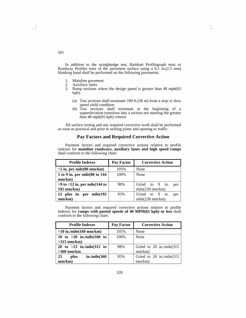
501
320
In addition to the straightedge test, Rainhart Profilograph tests or Roadway Profiler tests of the pavement surface using a 0.1 in.(2.5 mm) blanking band shall be performed on the following pavements:
1. Mainline pavement 2. Auxiliary lanes 3. Ramp sections where the design speed is greater than 40 mph(65
kph).
(a) Test sections shall terminate 100 ft.(30 m) from a stop or slow speed yield condition
(b) Test sections shall terminate at the beginning of a superelevation transition into a section not meeting the greater than 40 mph(65 kph) criteria
All surface testing and any required corrective work shall be performed
as soon as practical and prior to sealing joints and opening to traffic.
Pay Factors and Required Corrective Action Payment factors and required corrective actions relative to profile
indexes for mainline roadways, auxiliary lanes and high speed ramps shall conform to the following chart:
Profile Indexes Pay Factor Corrective Action
<5 in. per mile(80 mm/km) 105% None 5 to 9 in. per mile(80 to 144 mm/km)
100% None
>9 to <12 in. per mile(144 to 192 mm/km)
98% Grind to 9 in. per mile(230 mm/km)
12 plus in. per mile(192 mm/km)
93% Grind to 9 in. per mile(230 mm/km)
Payment factors and required corrective actions relative to profile
indexes for ramps with posted speeds of 40 MPH(65 kph) or less shall conform to the following chart:
Profile Indexes Pay Factor Corrective Action
<10 in./mile(160 mm/km) 105% None 10 to >20 in./mile(160 to >315 mm/km)
100% None
20 to >23 in./mile(315 to >360 mm/km
98% Grind to 20 in./mile(315 mm/km)
23 plus in./mile(360 mm/km)
95% Grind to 20 in./mile(315 mm/km)
501
321
High speed ramps between freeways that do not have stop or yield
conditions will be considered mainline pavement. For determining pavement sections where corrective work or pay adjustments will be necessary, the pavement will be evaluated in 0.1 mile(km) sections. All areas represented by high points having deviations in excess of 0.4 in.(10 mm) in 25 ft.(8 m) or less shall be corrected.
After corrective action is taken, the pavement will be retested and evaluated.
When the pavement being constructed abuts an adjacent pavement constructed under a previous contract, the adjacent pavement will be tested for smoothness. If the profile index of the existing pavement surface exceeds the above limits, the allowable profile index of the pavement surface being constructed will be increased by 1/2 the difference between the profile index of the existing pavement surface and the above requirements.
Any required correction shall be performed with approved grinding equipment or by removing and replacing the pavement as directed by the Engineer. Any area or section removed shall not be less than 10 ft(3 m) in length nor less than the full width of the lane involved. When it is necessary to remove and replace a section of pavement, any remaining portion of the slab adjacent to the joints that is less than 10 ft(3 m) in length shall also be removed and replaced. All corrective work shall be performed at the Contractor's expense.
Pavement that requires corrective grinding will be tested for thickness in accordance with Subsection 501.24 after grinding.
The Contractor shall establish positive means for removal of grinding and/or grooving residue. Solid residue shall be removed from pavement surfaces before being blown by traffic action or wind. Residue shall not be permitted to flow across lanes used by public traffic or into gutters or drainage facilities. Residue shall be disposed of in a manner that will prevent residue, whether in solid or slurry form, from reaching any waterway in a concentrated state.
Residue may be continuously discharged on adjacent roadway slopes or ditches if the Engineer determines that there is sufficient vegetative cover to adequately filter the residue. However, if the Engineer determines that there is not sufficient vegetative cover on the adjacent roadway slopes and ditches to adequately filter the residue, then the residue shall be collected in approved storage tanks and deposited in settling basins, spread over flat vegetated areas, or filtered by other means approved by the Engineer. 501.18-Curing. In all cases in which curing requires the use of water, the curing shall have prior right to all water supply or supplies. Failure to provide a sufficient quantity of one of the curing materials described under Section 913, or lack of water to adequately take care of both curing and other requirements shall be cause for immediate suspension of concreting operations. The concrete shall not be left exposed for more than 1/2 hour between stages of curing or during the curing period. Immediately after the finishing operations have been completed and as soon as marring of the
501
322
concrete will not occur, the entire surface of the newly placed concrete shall be covered and cured in accordance with one of the following methods:
(a) Cotton or Burlap Mats. The surface of the pavement shall be entirely covered with
mats. The mats used shall of such length(or width) that, as laid, they will extend at least twice the thickness of the pavement beyond the edges of the slab. The mats shall be placed so that the entire surface and both edges of the slab are completely covered. Prior to being placed, the mats shall be saturated thoroughly with water. The mats shall be so placed and weighted down as to cause them to remain in intimate contact with the surface covered, and the covering shall be maintained fully wetted and in position for 72 hours after the concrete has been placed unless otherwise specified.
(b) Waterproof Paper.
The top surface and sides of the pavement shall be entirely covered with waterproofed paper. The units shall be lapped at least 18 in.(450 mm). The paper shall be so placed and weighted down as to cause it to remain in intimate contact with the surface covered. The paper shall have such dimensions that each unit as laid will extend beyond the edges of the slab at least twice the thickness of the pavement, or it shall be of pavement width with 3 ft(1 m) strips of paper provided for the edges. If laid longitudinally, paper not manufactured in sizes which provide this width shall be cemented together in such a manner that the joints do not open up or separate during the curing period. Unless otherwise specified the covering shall be maintained in place for 72 hours after the concrete has been placed. The surface of the pavement shall be thoroughly wetted prior to the placing of the paper.
(c) Impervious Membrane Method.
The entire surface of the pavement shall be sprayed uniformly with white pigmented curing compound immediately after the finishing of the surface and before the set of the concrete has taken place, or if the pavement is cured initially with jute or cotton mats, it may be applied upon removal of the mats. The curing compound shall not be applied during rainfall.
Curing compound shall be applied under pressure by mechanical sprayers at the rate recommended by the manufacturer. The spraying equipment shall be of the fully atomizing type equipped with a tank agitator. At the time of use, the compound shall be in a thoroughly mixed condition with the pigment uniformly dispersed throughout the vehicle. During application, the compound shall be stirred continuously by effective mechanical means. Hand spraying of odd widths or shapes and concrete surfaces exposed by the removal of forms will be permitted. Curing compound shall not be applied to the inside
501
323
faces of joints to be sealed. Should the film become damaged from any cause within a 72 hour curing period, the damaged portions shall be repaired immediately with additional compound.
Upon removal of side forms, the sides of the slabs exposed shall be protected immediately by applying curing treatment equal to that provided for the surface.
(d) White Polyethylene Sheeting. The top surface and sides of the pavement shall be entirely
covered with polyethylene sheeting. The units used shall be lapped at least 18 in.(450 mm). The sheeting shall be so placed and weighted down as to cause it to remain in intimate contact with the surface covered. The sheeting as prepared for use shall have such dimension that each unit as laid will extend beyond the edges of the slab at least twice the thickness of the pavement. The surface of the pavement shall be thoroughly wetted prior to placing the sheeting. Unless otherwise specified, the covering shall be maintained in place for 72 hours after the concrete has been placed.
(e) Curing in Cold Weather.
When concrete is being placed and the air temperature may be expected to drop below 35° F(2° C) a sufficient supply of straw, hay, grass, or other suitable blanketing material shall be provided along the work and any time the temperature may be expected to reach the freezing point during the day or night, the material so provided shall be spread over the pavement to a sufficient depth to prevent freezing of the concrete. Care shall be taken not to mar the concrete surface. The period of time such protection shall be maintained shall be not less than 5 days. The Department reserves the right to require the Contractor to core the concrete.
The Contractor shall be responsible for the quality and strength of concrete laid during cold weather, and any concrete injured by freezing action shall be removed and replaced at his expense.
501.19-Removing Forms. Forms may be removed at any time that removal does not cause damage to the slab edges. The forms shall be removed carefully so as to avoid damage to the pavement. After the forms have been removed, the sides of the slab shall be cured as outlined in one of the methods indicated above. Honeycombed areas will be considered as defective work, and all unsound material shall be removed and replaced with satisfactory material at the Contractor's expense. 501.20-Sealing Joints. Joints shall be sealed with one of the specified joint sealing materials before the pavement is opened to traffic and as soon after completion of the curing period as is feasible. The sealant shall be selected from the Department’s QPL and shall be applied in strict accordance with the manufacturer’s recommendations. Just prior to sealing, each joint shall be thoroughly cleaned of all foreign material, including membrane curing
501
324
compound, by sand-blasting. All joints are to be high-pressure air blown prior to sealing. The joint faces shall be clean and dry when the seal is applied. The sealant shall be applied to the joint immediately after cleaning.
The sealing material shall be applied to each joint opening to conform to the details shown on the Plans or as directed by the Engineer. The sealing shall be done in such manner that material will not be spilled on the exposed surface of the concrete. Any excess material on the surface of the concrete pavement shall be removed immediately and the pavement surface cleaned.
Sealing material that does not bond to the concrete shall be removed, the joint recleaned, and resealed at the Contractor's expense.
All random cracks shall be reamed with a suitable tool and filled with an approved joint sealant. 501.21-Protection of Pavement. The Contractor shall protect the pavement and its appurtenances against both public traffic and traffic caused by his own employees and agents. This shall include watchmen to direct traffic and the erection and maintenance of the warning signs, lights, pavement bridges or cross-overs, etc.
Any damage to the pavement prior to final acceptance shall be repaired or the pavement replaced at the Contractor's expense.
All concrete paving shall be properly protected against the effects of rain before the concrete is sufficiently hardened; the Contractor will be required to have available at all times materials for the protection of the edges and surface of the plastic concrete. Such protective materials shall consist of standard metal forms or wood plank having a nominal thickness of not less than 2 in.(50 mm) and a nominal width of not less than the thickness of the pavement at its edge for the protection of the pavement edges, and covering material such as burlap or cotton mats, curing paper, or plastic sheeting material for the protection of the surface of the pavement. When rain appears imminent, all paving operations shall stop and all available personnel shall begin placing forms against the sides of the pavement and covering the surface of the plastic concrete with the protective covering. 501.22-Opening to Traffic. The Engineer will determine when the pavement will be opened to traffic. No traffic will be allowed on the completed pavement until the concrete has attained a compressive strength of 3,000 psi(20.7 MPa) or until 14 days after the concrete is placed, whichever occurs first. Concrete that fails to develop a compressive strength of 3,000 psi(20.7 MPa) within 28 days shall be removed and replaced at the Contractor's expense or accepted at a reduced price as provided in Subsection 501.13. Prior to opening to traffic, the pavement shall be cleaned and all joints shall be sealed. All other testing of the concrete pavement for smoothness and thickness shall be accomplished before opening to traffic. 501.23-Shoulders. Shoulders shall be constructed in accordance with these specifications and in reasonable close conformity to the lines, grades, and
501
325
typical cross sections shown on the plans or as directed by the Engineer. The construction, shaping, and dressing of the shoulders shall follow the completion of the pavement as closely as practicable and shall be one of the following types:
(a) Base with flexible surface
This work shall be performed in accordance with the applicable Section of Part 3--Base and Subgrade Treatments and the applicable Section of Part 4--Flexible Surfaces.
The longitudinal joints between the concrete pavement and the asphalt shoulder shall be prepared by sawing, unless otherwise directed by the Engineer, and shall form an opening 1 in. wide by 1 in.deep(25 mm wide by 25 mm deep) measured from the lowest elevation. The sealant shall be placed with equipment recommended by the sealant manufacturer which shall be capable of maintaining a uniform, homogeneous mixture throughout the sealing operation. The sealant shall be applied so that it flows into the joint without overlapping onto the pavement. All sealant which overlaps onto the pavement shall be removed by the Contractor at his expense.
(b) Base with rigid surface
This work shall be performed in accordance with the applicable Section of Part 3--Base and Subgrade Treatments and of Part 5--Rigid Pavement.
The longitudinal joint between the portland cement concrete pavement and the portland cement concrete shoulder shall be constructed in accordance with these specifications and with details shown on the plans. Materials used in this construction, including tie bars and joint sealant, shall be of the same type as the portland cement concrete roadway.
Transverse joints in the portland cement concrete shoulder shall correspond to the transverse joints in the portland cement concrete roadway and shall be of the same type, material, and spacing. Both expansion and contraction joints shall include dowel assemblies of the same type specified for the roadway pavement.
The cost of constructing the longitudinal joint between portland cement
concrete pavement and either flexible or rigid shoulders, shall be included in contract unit price per square yard(m2) of portland cement concrete pavement of the type and thickness specified on the plans. This price shall include all labor, equipment, materials, and incidentals required for the satisfactory performance of this work.
The cost of constructing transverse joints in the portland cement concrete shoulders shall be included in contract unit price per s.y.(m2) of portland cement concrete shoulder of the type and thickness specified on the plans. This price shall include all labor, equipment, materials, and incidentals required for the satisfactory performance of this work.

501
326
501.24-Tolerance in Pavement Thickness. The thickness of the pavement will be determined by average measurement of cores taken from each unit as set out below. For the purpose of determining the pavement thickness and for establishing an adjusted unit price for pavement that is deficient in thickness, units to be considered separately are defined, except as stipulated hereinafter, as pour widths 1,000 ft(300 m) in length, starting at the end of the pavement bearing the smaller station number. The pour width will be considered as the width of a separately poured lane or lanes. Last units having a length between 500 ft(150 m) and 1,000 ft(300 m) shall be treated as separate units. Last units having a length not exceeding 500 ft(150 m) shall be included in the last full unit. Units on interchange ramps shall be considered separately from units on the main line.
One core will be taken at random by the Department in each unit. When the measurement of the core from a unit is not deficient more than 1/4 in.(6 mm) from the Plan thickness, full payment will be made for the pavement in the area represented. When such measurement is deficient more than 1/4 in.(6 mm) and not more than 1 in.(25 mm) from the Plan thickness, 2 additional cores at intervals of not less than 300 ft(100 m) will be taken within the unit, and the average of 3 cores determined. If the average measurement of these 3 cores is not deficient more than 1/4 in.(6 mm) from the Plan thickness, full payment will be made. If the average thickness of the 3 cores is deficient by more than 1/4 in.(6 mm) but not more than 1 in.(25 mm) from the Plans thickness, an adjusted price as provided in Subsection 501.26(b) will be paid for the area represented by these cores.
Each intersection shall be considered as 1 unit. Small areas such as crossovers, entrances, etc., may be combined to form a unit of 1,000 s.y.(840 m2) or less. In each unit so established, thickness measurements shall be made and price adjustments, if any, applied as specified herein for pavement units on the main line and ramps, except the location and spacing of cores shall be as designated by the Engineer.
In calculating the average thickness of the pavement unit, measurements which are in excess of the average thickness by more than 1/4 in.(6 mm) will be considered as the specified thickness plus 1/4 in.(6 mm), and measurements which are less than the specified thickness by more than 1 in.(25 mm) will not be included in the average.
When the measurement of any core is less than the specified thickness by more than 1 in.(25 mm), the actual thickness of the pavement in this area will be determined by taking additional cores at not less than 10 ft(3 m) intervals parallel to the centerline in each direction from the affected location until a core is found, in each direction, which is not deficient by more than 1 in.(25 mm). Areas found deficient in thickness by more than 1 in.(25 mm) shall be evaluated by the Engineer, and if in his judgment, the deficient areas warrant removal, they shall be removed and replaced by and at the expense of Contractor, with concrete of the thickness shown on the Plans. Exploratory cores for areas deficient by more than 1 in.(25 mm) in thickness will not be used in averages for adjusted unit prices.
COMPENSATION
501
327
501.25-Method of Measurement. Portland Cement Concrete Pavement(Plain) and Portland Cement Concrete Pavement(Reinforced) of the various thicknesses specified, will be measured by the s.y.(m2) in accordance with the provisions of Section 109, Measurement and Payment.
Additional concrete required for leveling on individual ramps, including acceleration and deceleration lanes, containing 4,500 yards.y.(4,000 m2) or less will be measured by the c.y.(m3). Where a ramp becomes a traffic lane without a tapered acceleration lane or a traffic lane becomes a ramp without a tapered deceleration lane, 300 ft(100 m) of the lane, measured from the point of intersection with the adjoining lanes, will be considered as an acceleration or deceleration lane and included in the ramp. The number of c.y.(m3) of additional concrete will be determined by deducting the theoretical quantity and any wasted concrete from the number of c.y.(m3) actually used as determined from invoices or conversion from batch weights. Additional concrete used for leveling on main line roadway or ramps that contain more than 4,500 s.y.(4,000 m2) will not be measured for payment. 501.26-Basis of Payment.
(a) General. Payment for additional concrete used for leveling on ramps
that contain 4,500 s.y.(4,000 m2) or less will be based on the invoice price of the concrete when the concrete is purchased from a ready-mix producer. If the concrete is mixed on the project by the Contractor, the price per c.y.(m3) will be based on the invoice price of the materials plus 20%. Payment will be made on only that portion of additional concrete that exceeds 4% of the theoretical quantity; further, no payment will be made for additional concrete exceeding 10% of the theoretical quantity.
Payment will be made to the Contractor for additional cement measured as provided for under Subsection 501.25 at the purchase price, F.O.B. the unloading point, as verified by invoices, and no compensation will be allowed for further handling. The State will be reimbursed from monies due the Contractor for a decrease in cement measured as provided for under Subsection 501.25 in an mount equal to the purchase price of the cement, F.O.B. the unloading point. No payment will be allowed for any changes in the proportions of the aggregates.
The accepted quantities of Portland Cement Concrete Pavement will be paid for at the contract unit price per s.y.(m2), for each specified thickness, for Portland Cement Concrete Pavement (Plain), and Portland Cement Concrete Pavement (Reinforced), which payment shall be full compensation for furnishing all materials including reinforcing, dowels, and joint material. Provided, however, for any pavement found deficient in thickness by more than 1/4 in.(6 mm), but not more than 1 in.(25 mm), only the reduced price stipulated in (b) will be paid. No additional payment over the contract unit bid price will be made for
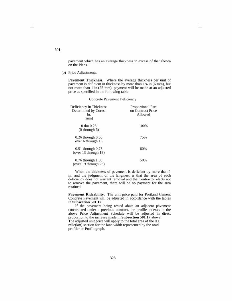
501
328
pavement which has an average thickness in excess of that shown on the Plans.
(b) Price Adjustments.
Pavement Thickness. Where the average thickness per unit of pavement is deficient in thickness by more than 1/4 in.(6 mm), but not more than 1 in.(25 mm), payment will be made at an adjusted price as specified in the following table:
Concrete Pavement Deficiency
Deficiency in Thickness Proportional Part Determined by Cores, on Contract Price In. Allowed (mm) 0 thu 0.25 100% (0 through 6) 0.26 through 0.50 75% over 6 through 13 0.51 through 0.75 60% (over 13 through 19) 0.76 through 1.00 50% (over 19 through 25)
When the thickness of pavement is deficient by more than 1 in. and the judgment of the Engineer is that the area of such deficiency does not warrant removal and the Contractor elects not to remove the pavement, there will be no payment for the area retained.
Pavement Rideability. The unit price paid for Portland Cement Concrete Pavement will be adjusted in accordance with the tables in Subsection 501.17.
If the pavement being tested abuts an adjacent pavement constructed under a previous contract, the profile indexes in the above Price Adjustment Schedule will be adjusted in direct proportion to the increase made in Subsection 501.17 above. The adjusted unit price will apply to the total area of the 0.1 mile(km) section for the lane width represented by the road profiler or Profilograph.