CONSTRUCTION OF NAGISA BRIDGE HYBRID SYSTEM OF CABLE-STAYED PC
8
CONSTRUCTION OF NAGISA BRIDGE HYBRID SYSTEM OF CABLE-STAYED PC BRIDGE AND STEEL SUSPENSION BRIDGE Yuzuru Sato 1 Shinichi Sasaki 2 Katsutoshi Morohashi 3 Nobumasa Suzuki 4 Abstract Nagisa Bridge, a single span footbridge, was recently completed in Aomori prefecture, Japan. The structure of this bridge is a hybrid structure of cable-stayed prestressed concrete bridge and steel suspension bridge. It is the first application as this structure type of bridge in the world. Concrete girders near pylons are supported by stay cables. Steel girders are supported by suspension cables in the central part of the span. This is new type system for prestressed concrete bridges with longer span and has many structural features compared with ordinary cable-stayed bridge and suspension bridge. This paper reports a brief overview of construction of Nagisa Bridge with this hybrid system. 1. Introduction Nagisa Bridge, a single span footbridge recently constructed over the Nakamura river mouth in Aomori prefecture, Japan, is the first hybrid system bridge in the world that is a compound structure of cable-stayed prestressed concrete (PC) bridge and steel suspension bridge ( Photo 1 ). PC girders are used for the stay cable sections near pylons. And steel girders are used for the suspended cable section in the central part of the span. There are two bridges which adopted a similar combination of cable-stayed system and cable-suspended system. These are Saint-Ilpize bridge in France [1] and Sidi M’Cid Bridge in Algeria [2]. Both bridges, however, have steel decks only. Nagisa Bridge is the first application of a hybrid system with a combination of PC girder and steel girder. About the design of Nagisa Bridge, some requirements had to be satisfied. These were to eliminate piers in the river and to design the bridge which would be perceived as a landmark of this area. In consideration of these conditions, the hybrid system which can be made having long span and characteristic appearance was selected. This paper reports a brief overview of construction of Nagisa Bridge with the new hybrid system, including field tests conducted prior to the opening of the bridge. 1. Nishi Agriculture, Forestry, and Fisheries Office / Nishi Fisheries Infrastructure Office, Aomor i Prefecture Japan 2. 3. 4. P.S.Mitsubishi Construction Co., Ltd
Transcript of CONSTRUCTION OF NAGISA BRIDGE HYBRID SYSTEM OF CABLE-STAYED PC

CONSTRUCTION OF NAGISA BRIDGE HYBRID SYSTEM OF CABLE-STAYED PC BRIDGE AND STEEL SUSPENSION BRIDGE
Yuzuru Sato1 Shinichi Sasaki2
Katsutoshi Morohashi3 Nobumasa Suzuki4
Abstract
Nagisa Bridge, a single span footbridge, was recently completed in Aomori prefecture, Japan. The structure of this bridge is a hybrid structure of cable-stayed prestressed concrete bridge and steel suspension bridge. It is the first application as this structure type of bridge in the world. Concrete girders near pylons are supported by stay cables. Steel girders are supported by suspension cables in the central part of the span. This is new type system for prestressed concrete bridges with longer span and has many structural features compared with ordinary cable-stayed bridge and suspension bridge. This paper reports a brief overview of construction of Nagisa Bridge with this hybrid system. 1. Introduction Nagisa Bridge, a single span footbridge recently constructed over the Nakamura river mouth in Aomori prefecture, Japan, is the first hybrid system bridge in the world that is a compound structure of cable-stayed prestressed concrete (PC) bridge and steel suspension bridge (Photo 1). PC girders are used for the stay cable sections near pylons. And steel girders are used for the suspended cable section in the central part of the span. There are two bridges which adopted a similar combination of cable-stayed system and cable-suspended system. These are Saint-Ilpize bridge in France [1] and Sidi M’Cid Bridge in Algeria [2]. Both bridges, however, have steel decks only. Nagisa Bridge is the first application of a hybrid system with a combination of PC girder and steel girder.
About the design of Nagisa Bridge, some requirements had to be satisfied. These were to eliminate piers in the river and to design the bridge which would be perceived as a landmark of this area. In consideration of these conditions, the hybrid system which can be made having long span and characteristic appearance was selected. This paper reports a brief overview of construction of Nagisa Bridge with the new hybrid system, including field tests conducted prior to the opening of the bridge.
1. Nishi Agriculture, Forestry, and Fisheries Office / Nishi Fisheries Infrastructure Office, AomoriPrefecture Japan
2. 3. 4. P.S.Mitsubishi Construction Co., Ltd

2. Hybrid System Bridge Features
The hybrid system bridge has many structural features compared with ordinary cable-stayed bridge and suspension bridge. Fig.1 shows concepts of the hybrid system bridge and ordinary cable supported bridges. In comparison with cable-stayed bridge, this system has better buckling stability and is applicable for longer span, because the axial force occurring in the girder can be reduced by decreasing the number of stay cables. Cable erection can be easier and cable vibration problems can be solved due to shorter stay cables. The height of pylons can be lowered by reducing the number of stay cables. In comparison with suspension bridge, this system has better aerodynamic stability, because the stay cables restrain the deformation of the girder. It is achieved to lessen the tension force occurring in the main cables, because the stay cables support more weight. And anchorage lateral force can be reduced.
SteelGirder PC Girder Steel Girder PC Girder
SteelGirder
(a) Hybrid System Bridge
(b) Suspension Bridge
(c) Cable-Stayed Bridge Fig.1 Concepts of Cable Supported Bride
Photo 1 Nagisa Bridge
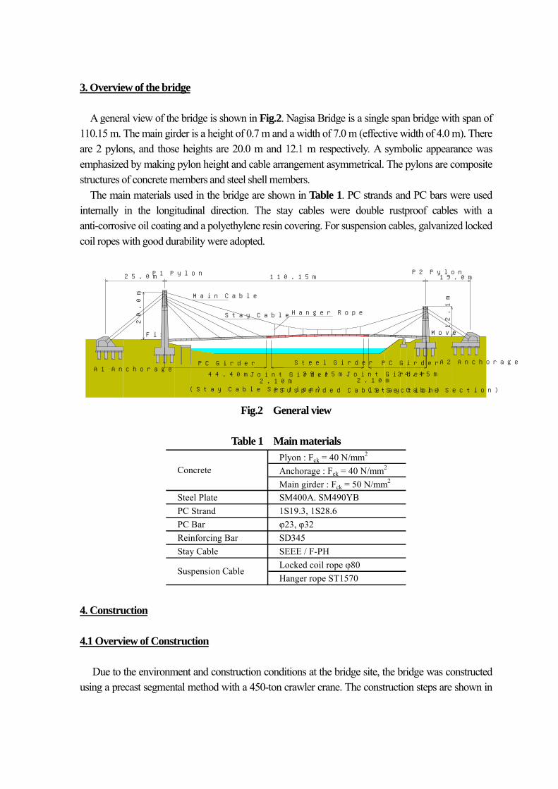
3. Overview of the bridge
A general view of the bridge is shown in Fig.2. Nagisa Bridge is a single span bridge with span of 110.15 m. The main girder is a height of 0.7 m and a width of 7.0 m (effective width of 4.0 m). There are 2 pylons, and those heights are 20.0 m and 12.1 m respectively. A symbolic appearance was emphasized by making pylon height and cable arrangement asymmetrical. The pylons are composite structures of concrete members and steel shell members.
The main materials used in the bridge are shown in Table 1. PC strands and PC bars were used internally in the longitudinal direction. The stay cables were double rustproof cables with a anti-corrosive oil coating and a polyethylene resin covering. For suspension cables, galvanized locked coil ropes with good durability were adopted.
P1 Pylon
20.0m
25.0m
Main Cable
Move
19.0m110.15mP2 Pylon
12.1m
Stay Cable Hanger Rope
(Stay Cable Section)(Suspended Cable Section)(Stay Cable Section)
2.10mJoint Girder
2.10mJoint Girder44.40m
A1 Anchorage39.15m
Steel Girder PC Girder A2 AnchoragePC Girder
24.45m
Fix
Fig.2 General view
Table 1 Main materials
Plyon : Fck = 40 N/mm2
Anchorage : Fck = 40 N/mm2
Main girder : Fck = 50 N/mm2
Steel Plate SM400A. SM490YBPC Strand 1S19.3, 1S28.6PC Bar φ23, φ32Reinforcing Bar SD345Stay Cable SEEE / F-PH
Locked coil rope φ80Hanger rope ST1570
Concrete
Suspension Cable
4. Construction 4.1 Overview of Construction
Due to the environment and construction conditions at the bridge site, the bridge was constructed using a precast segmental method with a 450-ton crawler crane. The construction steps are shown in

Fig.3. On the first step, the pylons and the anchorages for the suspension cables and the back stay cables were constructed. On the second step, cantilever erection of concrete segments was performed, and the stay cables were installed every four segments. On the third step, the suspension cables were placed and steel girders were erected. On the last step, concrete was placed around the steel shell members anchoring the stay cables on the pylons, and pavement was placed on the girder.
450t
450t
444544444400000700000555555555544444444444777777755577777777777000000000007777700070
44444447777577444455554444444557555555555775777777775577770000
5
000000000
545445555555445
44450445555445077770000000000
STEP 1 : Construction of
STEP 4 : Installation of pavement and railing
STEP 3 : Erection of steel girders
STEP 2 : Cantilever erection
of concrete segments
pylons and anchorages
Fig.3 Construction step 4.2 Fabrication of Main Girders
Fig.4 shows sections of the main PC girder and the main steel girders. The section was designed in consideration of wind stability, durability, and reduction in self-weight. Concrete segment fabrication was done using the long line match-cast method in the factory (Photo 2). The length of each segment was 2.25 m, and its weight was about 220 kN. Steel segments were fabricated in the factory, with a length of 3.0 m and a weight of 70 kN.
It was very important for the jointing segment to transfer the stress between the PC girder and the steel girder smoothly. The jointing segment comprised of a combination of a concrete member and a steel member (Fig.5). The steel member was fabricated first, and filled with self-compacting concrete. The concrete member was fabricated using the match-cast method, and finally prestressing was introduced in order to control crack width caused by the restraint on the concrete at early age.
(b)Steel girder section
CL
1.5m 4.0m 1.5m
7.0m
0.7m
(a)PC girder section
CL
1.5m 4.0m 1.5m
7.0m
0.7m
Fig.4 Main girder section

Composite MenberConcrete Member
Stud Bolt Front Plate Back Plate
Self-Compacting Concrete
PC Bars
0.60m 1.00m 0.50mSteel Member
2.10mJointing Segment
0.700m
0.012m
0.012m
0.676m
Photo 2 Fabrication of concrete segments Fig.5 Jointing segment
4.3 Construction of Pylons and Anchorages The main bodies of pylons are reinforced concrete structures. In order to make the pylon more compact, steel members were adopted to anchor the stay cables to the pylon (Fig.6). After the concrete section for 2/3 of the pylon was constructed, steel shell members were placed on top of it (Photo 3). After the cantilever erection of the concrete girders and the erection of the steel girders had completed, concrete was placed around the steel shell members to create an integrated unit. The anchorages have very dense bar arrangement. Therefore, self-compacting concrete with a slump flow of 65 cm was used. Concrete volume was 175 m3 for the left anchorage and 162 m3 for the right one.
0.88m
1.00m
0.80m
2.00m
1.60m
5.00m
0.50m
Fig.6 Steel shell member of P1 Photo 3 Steel shell member of P2

4.4 Erection of Concrete Segments Cantilever erection of concrete segments was performed by using a 450-ton crane without any false work and scaffolding in the river (Photo 4). Cantilever erection was made by tensioning the inner PC bars at each segment. The stay cables, which were fabricated in a factory, were installed every four segments (anchorage span of 9 m). 4.5 Erection of Steel Girders When the erection of the concrete segments and the jointing segments were completed, the suspension cables were placed from A1 anchorage to A2 anchorage through the saddles on top of the pylons using a winch and a crane. The steel girder segments were hung on the hanger lopes using a 450-ton crane (Photo 5). Connection of each steel segments and connection of the jointing segments and steel segments was conducted, after all of the steel segments were suspended.
Photo 4 Erection of concrete segments
Photo 5 Erection of steel girders

5. Field Test
Prior to the opening of Nagisa Bridge, the field loading tests were conducted in order to verify the performance of the bridge system and the validity of the analysis method. Two loaded vehicles, each weight of 42 kN, were used for the tests (Photo 6). Fig.7 shows the mid-span deformation measured when loaded in the center of the span, including the results of the finite deformation analysis with the 2 dimensional model. The test results did not indicate a complicated performance, even if different bridge systems, cable-stayed PC bridge and steel suspension bridge, were combined. The measured values are lower than the analytical values a little, but the trend is very similar.
Photo 6 Field test
-50
-45
-40
-35
-30
-25
-20
-15
-10
-5
0
0 10 20 30 40 50 60 70 80 90 100 110
X-coordinate(m)
disp
lacem
ent(
mm
)
Analytical Value
Measured Value
Fig.7 Results of measurement of deformation

6. Conclusions Nagisa Bridge was the first challenge as a compound bridge of cable-stayed prestressed concrete bridge and steel suspension bridge. Therefore there were many problems to deal with during design, material selection, and execution. Nagisa Bridge, however, was completed in December 2002. And the bridge was opened for pedestrians in July 2003.
It is clear that the hybrid system bridge of cable-stayed PC bridge and steel suspension bridge has many features and is competitive in comparison with ordinary cable supported bridges. The successful completion of Nagisa Bridge demonstrated the superior feature of the hybrid system. And the behavior of such bridges with the hybrid system was verified by conducting field loading tests. It is expected that the adoption of the hybrid system for longer span bridge will increase in the future. References [1] Marcel PRADE : “PONTS et VIADUCS au XIXe SIECLE.”, ERRANCE, BRISSAUD, 1988,
pp.112-113 [2] Macro PETRANGELI, Marcello PETRANGELI : Rehabilitation of Sidi N’Cid Suspension
Bridge, Algeria , Structural Engineering International , Vol.10, No.4, 2000, pp.254-258 [3] Y.SATO, K.NOGUCHI, K.SUZUKI, K.MOROHASHI, S.NAKAI : Design and Construction of
Nagisa Bridge, Journal of Prestressed Concrete, Japan, Vol.45, No.3, May 2003, pp.22-27 [4] Y.SATO, S.SASAKI, K.MOROHASHI, N.SUZUKI : Construction and Field Tests of Nagisa
Bridge –Hybrid System of Cable-Stayed PC Bridge and Steel Suspension Bridge– , Bridge and Foundation Engineering, Vol.37, No.7, 2003, pp.2-9