Construction of an Amateur Radio Astronomy Antenna
24
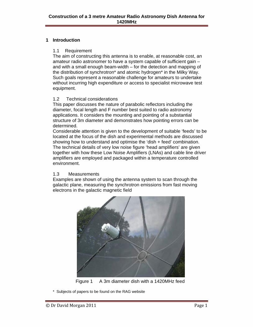
Construction of a 3 metre Amateur Radio Astronomy Dish Antenna for 1420MHz © Dr David Morgan 2011 Page 1 1 Introduction 1.1 Requirement The aim of constructing this antenna is to enable, at reasonable cost, an amateur radio astronomer to have a system capable of sufficient gain – and with a small enough beam-width – for the detection and mapping of the distribution of synchrotron* and atomic hydrogen* in the Milky Way. Such goals represent a reasonable challenge for amateurs to undertake without incurring high expenditure or access to specialist microwave test equipment. 1.2 Technical considerations This paper discusses the nature of parabolic reflectors including the diameter, focal length and F number best suited to radio astronomy applications. It considers the mounting and pointing of a substantial structure of 3m diameter and demonstrates how pointing errors can be determined. Considerable attention is given to the development of suitable ‘feeds’ to be located at the focus of the dish and experimental methods are discussed showing how to understand and optimise the ‘dish + feed’ combination. The technical details of very low noise figure ‘head amplifiers’ are given together with how these Low Noise Amplifiers (LNAs) and cable line driver amplifiers are employed and packaged within a temperature controlled environment. 1.3 Measurements Examples are shown of using the antenna system to scan through the galactic plane, measuring the synchrotron emissions from fast moving electrons in the galactic magnetic field Figure 1 A 3m diameter dish with a 1420MHz feed * Subjects of papers to be found on the RAG website
-
Upload
astronomer-bilal -
Category
Documents
-
view
335 -
download
15
Transcript of Construction of an Amateur Radio Astronomy Antenna
Construction of a 3 metre Amateur Radio Astronomy Dish Antenna for 1420MHz
© Dr David Morgan 2011 Page 1
1 Introduction
1.1 Requirement The aim of constructing this antenna is to enable, at reasonable cost, an amateur radio astronomer to have a system capable of sufficient gain – and with a small enough beam-width – for the detection and mapping of the distribution of synchrotron* and atomic hydrogen* in the Milky Way. Such goals represent a reasonable challenge for amateurs to undertake without incurring high expenditure or access to specialist microwave test equipment. 1.2 Technical considerations This paper discusses the nature of parabolic reflectors including the diameter, focal length and F number best suited to radio astronomy applications. It considers the mounting and pointing of a substantial structure of 3m diameter and demonstrates how pointing errors can be determined. Considerable attention is given to the development of suitable ‘feeds’ to be located at the focus of the dish and experimental methods are discussed showing how to understand and optimise the ‘dish + feed’ combination. The technical details of very low noise figure ‘head amplifiers’ are given together with how these Low Noise Amplifiers (LNAs) and cable line driver amplifiers are employed and packaged within a temperature controlled environment. 1.3 Measurements Examples are shown of using the antenna system to scan through the galactic plane, measuring the synchrotron emissions from fast moving electrons in the galactic magnetic field
Figure 1 A 3m diameter dish with a 1420MHz feed
* Subjects of papers to be found on the RAG website
Construction of a 3 metre Amateur Radio Astronomy Dish Antenna for 1420MHz
© Dr David Morgan 2011 Page 2
2 Parabolic Reflector Antennas
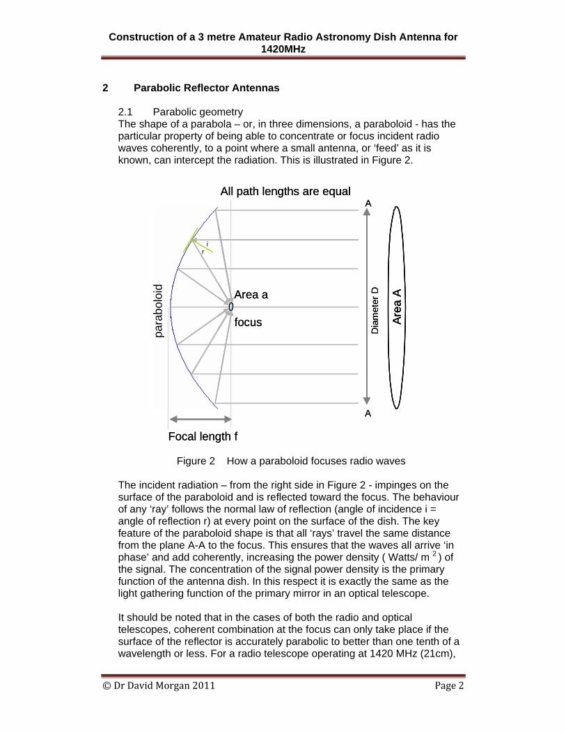
2.1 Parabolic geometry The shape of a parabola – or, in three dimensions, a paraboloid - has the particular property of being able to concentrate or focus incident radio waves coherently, to a point where a small antenna, or ‘feed’ as it is known, can intercept the radiation. This is illustrated in Figure 2.
Figure 2 How a paraboloid focuses radio waves
The incident radiation – from the right side in Figure 2 - impinges on the surface of the paraboloid and is reflected toward the focus. The behaviour of any ‘ray’ follows the normal law of reflection (angle of incidence i = angle of reflection r) at every point on the surface of the dish. The key feature of the paraboloid shape is that all ‘rays’ travel the same distance from the plane A-A to the focus. This ensures that the waves all arrive ‘in phase’ and add coherently, increasing the power density ( Watts/ m 2 ) of the signal. The concentration of the signal power density is the primary function of the antenna dish. In this respect it is exactly the same as the light gathering function of the primary mirror in an optical telescope. It should be noted that in the cases of both the radio and optical telescopes, coherent combination at the focus can only take place if the surface of the reflector is accurately parabolic to better than one tenth of a wavelength or less. For a radio telescope operating at 1420 MHz (21cm),
Area a
Area
A
All path lengths are equal
para
bolo
id
focus
Dia
met
er D
Focal length f
ir
A
A
Area a
Area
AAr
ea A
All path lengths are equal
para
bolo
id
focus
Dia
met
er D
Focal length f
ir
A
A
Construction of a 3 metre Amateur Radio Astronomy Dish Antenna for 1420MHz
© Dr David Morgan 2011 Page 3
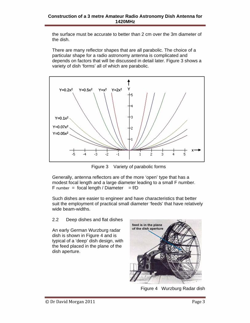
the surface must be accurate to better than 2 cm over the 3m diameter of the dish. There are many reflector shapes that are all parabolic. The choice of a particular shape for a radio astronomy antenna is complicated and depends on factors that will be discussed in detail later. Figure 3 shows a variety of dish ‘forms’ all of which are parabolic.
Figure 3 Variety of parabolic forms Generally, antenna reflectors are of the more ‘open’ type that has a modest focal length and a large diameter leading to a small F number. F number = focal length / Diameter = f/D Such dishes are easier to engineer and have characteristics that better suit the employment of practical small diameter ‘feeds’ that have relatively wide beam-widths. 2.2 Deep dishes and flat dishes
An early German Wurzburg radar dish is shown in Figure 4 and is typical of a ‘deep’ dish design, with the feed placed in the plane of the dish aperture.
Figure 4 Wurzburg Radar dish
Y=0.05x2
Y=0.07x2
Y=0.1x2
Y=0.2x2 Y=0.5x2 Y=x2 Y=2x2
x
Y
Y=0.05x2
Y=0.07x2
Y=0.1x2
Y=0.2x2 Y=0.5x2 Y=x2 Y=2x2
x
Y
Construction of a 3 metre Amateur Radio Astronomy Dish Antenna for 1420MHz
© Dr David Morgan 2011 Page 4
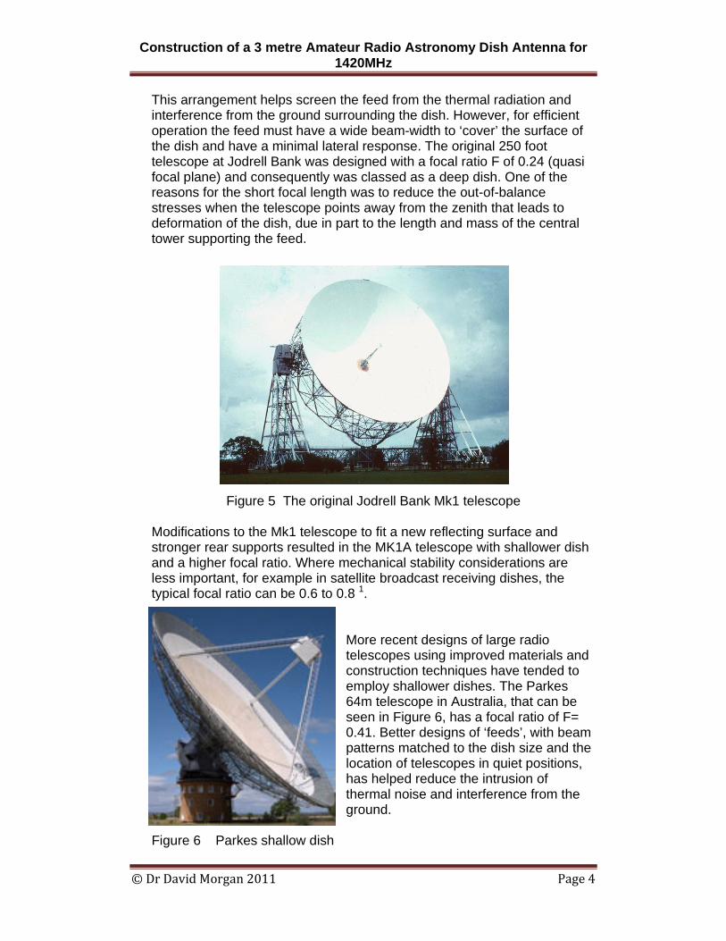
This arrangement helps screen the feed from the thermal radiation and interference from the ground surrounding the dish. However, for efficient operation the feed must have a wide beam-width to ‘cover’ the surface of the dish and have a minimal lateral response. The original 250 foot telescope at Jodrell Bank was designed with a focal ratio F of 0.24 (quasi focal plane) and consequently was classed as a deep dish. One of the reasons for the short focal length was to reduce the out-of-balance stresses when the telescope points away from the zenith that leads to deformation of the dish, due in part to the length and mass of the central tower supporting the feed.
Figure 5 The original Jodrell Bank Mk1 telescope
Modifications to the Mk1 telescope to fit a new reflecting surface and stronger rear supports resulted in the MK1A telescope with shallower dish and a higher focal ratio. Where mechanical stability considerations are less important, for example in satellite broadcast receiving dishes, the typical focal ratio can be 0.6 to 0.8 1.
More recent designs of large radio telescopes using improved materials and construction techniques have tended to employ shallower dishes. The Parkes 64m telescope in Australia, that can be seen in Figure 6, has a focal ratio of F= 0.41. Better designs of ‘feeds’, with beam patterns matched to the dish size and the location of telescopes in quiet positions, has helped reduce the intrusion of thermal noise and interference from the ground.
Figure 6 Parkes shallow dish
Construction of a 3 metre Amateur Radio Astronomy Dish Antenna for 1420MHz
© Dr David Morgan 2011 Page 5
Dish surface
Feed tower
Dipole feed
Dish surface
Feed tower
Dipole feed
3 Feed designs and matching to dish shape
3.1 Basic feed types
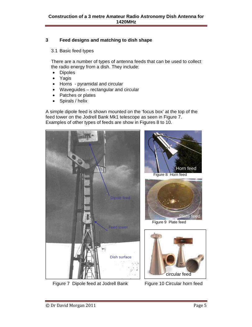
There are a number of types of antenna feeds that can be used to collect the radio energy from a dish. They include: • Dipoles • Yagis • Horns - pyramidal and circular • Waveguides – rectangular and circular • Patches or plates • Spirals / helix
A simple dipole feed is shown mounted on the ‘focus box’ at the top of the feed tower on the Jodrell Bank Mk1 telescope as seen in Figure 7. Examples of other types of feeds are show in Figures 8 to 10.
Figure 7 Dipole feed at Jodrell Bank Figure 10 Circular horn feed
Plate feed
Horn feed Figure 8 Horn feed
Figure 9 Plate feed
circular feed
Construction of a 3 metre Amateur Radio Astronomy Dish Antenna for 1420MHz
© Dr David Morgan 2011 Page 6
x
x
x
x
x
x
x
x
.
.
.
.
.
.
.
.
.
.
..
.
.
xx
x
x
x
x
2a
TE1,1
E
H
x
x
x
x
x
x
x
x
x
x
x
x
x
x
x
x
.
.
.
.
.
.
.
.
.
.
.
.
.
.
.
.
.
.
.
.
.
.
.
.
.
.
..
.
.
xx
x
x
x
x
2a
TE1,1
E
H
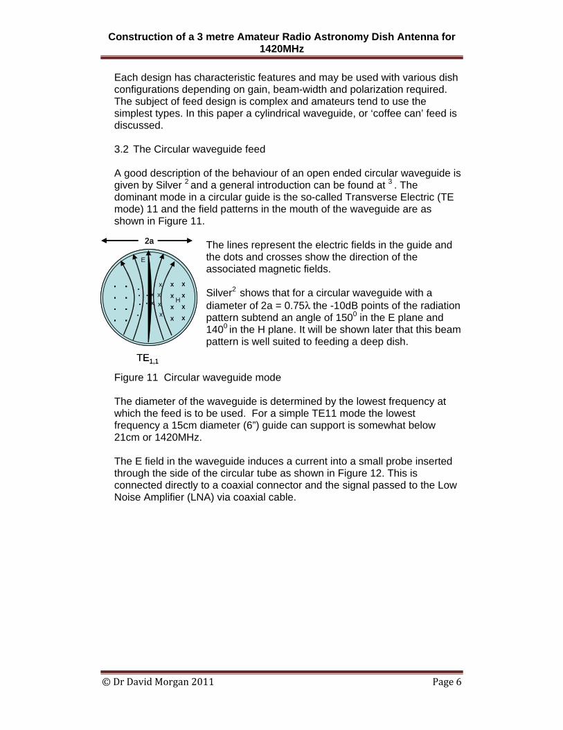
Each design has characteristic features and may be used with various dish configurations depending on gain, beam-width and polarization required. The subject of feed design is complex and amateurs tend to use the simplest types. In this paper a cylindrical waveguide, or ‘coffee can’ feed is discussed. 3.2 The Circular waveguide feed A good description of the behaviour of an open ended circular waveguide is given by Silver 2 and a general introduction can be found at 3 . The dominant mode in a circular guide is the so-called Transverse Electric (TE mode) 11 and the field patterns in the mouth of the waveguide are as shown in Figure 11.
The lines represent the electric fields in the guide and the dots and crosses show the direction of the associated magnetic fields. Silver2 shows that for a circular waveguide with a diameter of 2a = 0.75λ the -10dB points of the radiation pattern subtend an angle of 1500 in the E plane and 1400 in the H plane. It will be shown later that this beam pattern is well suited to feeding a deep dish.
Figure 11 Circular waveguide mode The diameter of the waveguide is determined by the lowest frequency at which the feed is to be used. For a simple TE11 mode the lowest frequency a 15cm diameter (6”) guide can support is somewhat below 21cm or 1420MHz. The E field in the waveguide induces a current into a small probe inserted through the side of the circular tube as shown in Figure 12. This is connected directly to a coaxial connector and the signal passed to the Low Noise Amplifier (LNA) via coaxial cable.
Construction of a 3 metre Amateur Radio Astronomy Dish Antenna for 1420MHz
© Dr David Morgan 2011 Page 7
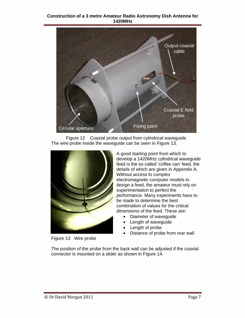
Figure 12 Coaxial probe output from cylindrical waveguide The wire probe inside the waveguide can be seen in Figure 13.
A good starting point from which to develop a 1420MHz cylindrical waveguide feed is the so called ‘coffee can’ feed, the details of which are given in Appendix A. Without access to complex electromagnetic computer models to design a feed, the amateur must rely on experimentation to perfect the performance. Many experiments have to be made to determine the best combination of values for the critical dimensions of the feed. These are:
• Diameter of waveguide • Length of waveguide • Length of probe • Distance of probe from rear wall
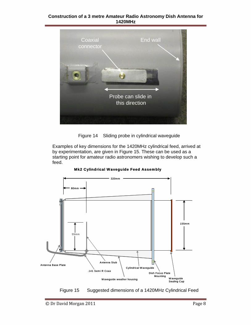
Figure 13 Wire probe The position of the probe from the back wall can be adjusted if the coaxial connector is mounted on a slider as shown in Figure 14.
Circular aperture Fixing point
Coaxial E fieldprobe
Output coaxialcable
Circular aperture Fixing point
Coaxial E fieldprobe
Output coaxialcable
Construction of a 3 metre Amateur Radio Astronomy Dish Antenna for 1420MHz
© Dr David Morgan 2011 Page 8
Figure 14 Sliding probe in cylindrical waveguide Examples of key dimensions for the 1420MHz cylindrical feed, arrived at by experimentation, are given in Figure 15. These can be used as a starting point for amateur radio astronomers wishing to develop such a feed.
Figure 15 Suggested dimensions of a 1420MHz Cylindrical Feed
Probe can slide in this direction
End wallCoaxialconnector
Probe can slide in this direction
End wallCoaxialconnector
Antenna Base Plate
W aveguide weather housing
Cylindrical W aveguide.141 Sem i R Coax
Antenna Stub
W aveguide Sealing Cap
Dish Focus Plate Mounting
Mk2 Cylindrical W aveguide Feed Assembly
320mm
80mm
55mm
155mm
Antenna Base Plate
W aveguide weather housing
Cylindrical W aveguide.141 Sem i R Coax
Antenna Stub
W aveguide Sealing Cap
Dish Focus Plate Mounting
Mk2 Cylindrical W aveguide Feed Assembly
320mm
80mm
55mm
155mm
Construction of a 3 metre Amateur Radio Astronomy Dish Antenna for 1420MHz
© Dr David Morgan 2011 Page 9
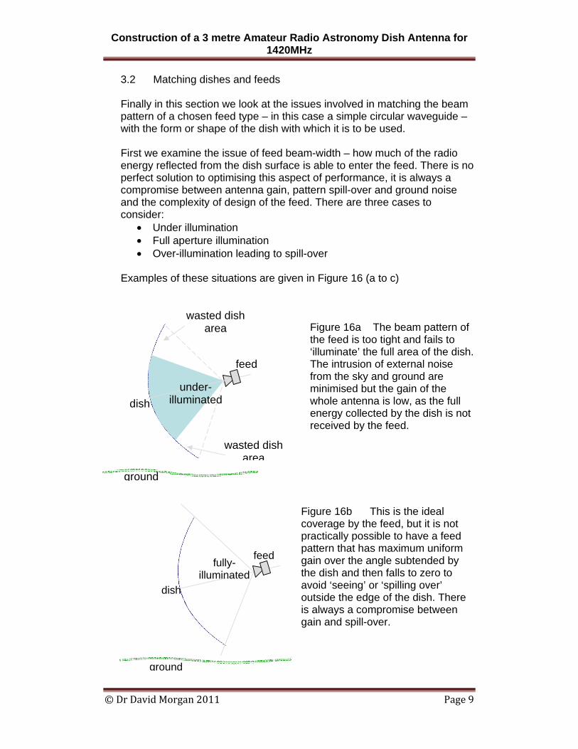
3.2 Matching dishes and feeds Finally in this section we look at the issues involved in matching the beam pattern of a chosen feed type – in this case a simple circular waveguide – with the form or shape of the dish with which it is to be used. First we examine the issue of feed beam-width – how much of the radio energy reflected from the dish surface is able to enter the feed. There is no perfect solution to optimising this aspect of performance, it is always a compromise between antenna gain, pattern spill-over and ground noise and the complexity of design of the feed. There are three cases to consider:
• Under illumination • Full aperture illumination • Over-illumination leading to spill-over
Examples of these situations are given in Figure 16 (a to c)
Figure 16a The beam pattern of the feed is too tight and fails to ‘illuminate’ the full area of the dish. The intrusion of external noise from the sky and ground are minimised but the gain of the whole antenna is low, as the full energy collected by the dish is not received by the feed.
Figure 16b This is the ideal coverage by the feed, but it is not practically possible to have a feed pattern that has maximum uniform gain over the angle subtended by the dish and then falls to zero to avoid ‘seeing’ or ‘spilling over’ outside the edge of the dish. There is always a compromise between gain and spill-over.
feed
dish under-
illuminated
wasted dish area
wasted dish area
ground
fully- illuminated
dish
feed
ground
Construction of a 3 metre Amateur Radio Astronomy Dish Antenna for 1420MHz
© Dr David Morgan 2011 Page 10
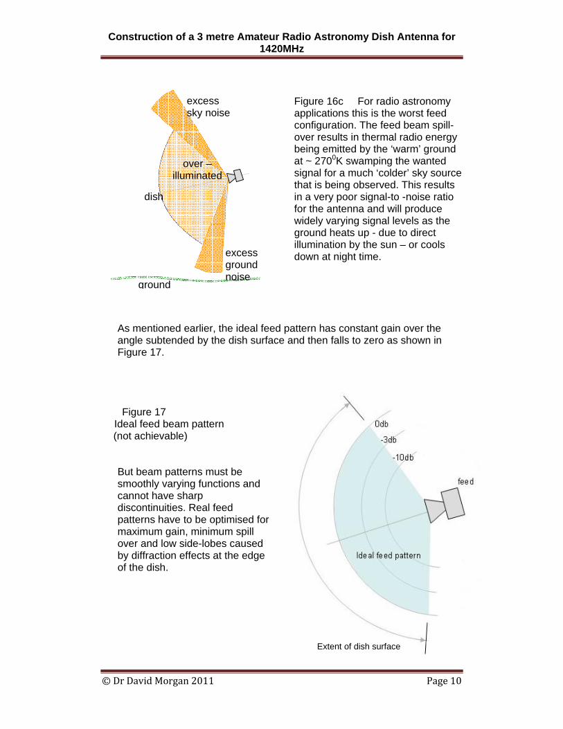
Figure 16c For radio astronomy applications this is the worst feed configuration. The feed beam spill-over results in thermal radio energy being emitted by the ‘warm’ ground at ~ 2700K swamping the wanted signal for a much ‘colder’ sky source that is being observed. This results in a very poor signal-to -noise ratio for the antenna and will produce widely varying signal levels as the ground heats up - due to direct illumination by the sun – or cools down at night time.
As mentioned earlier, the ideal feed pattern has constant gain over the angle subtended by the dish surface and then falls to zero as shown in Figure 17.
Figure 17 Ideal feed beam pattern
(not achievable)
But beam patterns must be smoothly varying functions and cannot have sharp discontinuities. Real feed patterns have to be optimised for maximum gain, minimum spill over and low side-lobes caused by diffraction effects at the edge of the dish.
over – illuminated
excess ground noise
excess sky noise
dish
ground
Extent of dish surface
Construction of a 3 metre Amateur Radio Astronomy Dish Antenna for 1420MHz
© Dr David Morgan 2011 Page 11
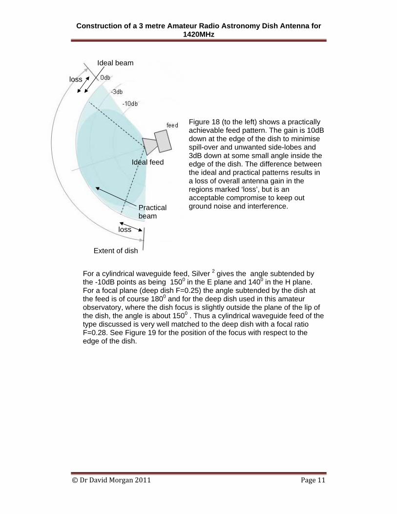
Figure 18 (to the left) shows a practically achievable feed pattern. The gain is 10dB down at the edge of the dish to minimise spill-over and unwanted side-lobes and 3dB down at some small angle inside the edge of the dish. The difference between the ideal and practical patterns results in a loss of overall antenna gain in the regions marked ‘loss’, but is an acceptable compromise to keep out ground noise and interference.
For a cylindrical waveguide feed, Silver 2 gives the angle subtended by the -10dB points as being 1500 in the E plane and 1400 in the H plane. For a focal plane (deep dish F=0.25) the angle subtended by the dish at the feed is of course 1800 and for the deep dish used in this amateur observatory, where the dish focus is slightly outside the plane of the lip of the dish, the angle is about 1500 . Thus a cylindrical waveguide feed of the type discussed is very well matched to the deep dish with a focal ratio F=0.28. See Figure 19 for the position of the focus with respect to the edge of the dish.
Ideal feed
Ideal beam
Practical beam
Extent of dish
loss
loss
Construction of a 3 metre Amateur Radio Astronomy Dish Antenna for 1420MHz
© Dr David Morgan 2011 Page 12
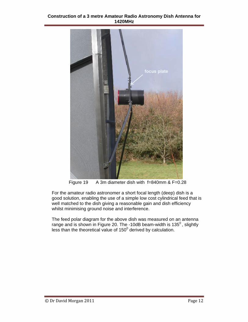
Figure 19 A 3m diameter dish with f=840mm & F=0.28
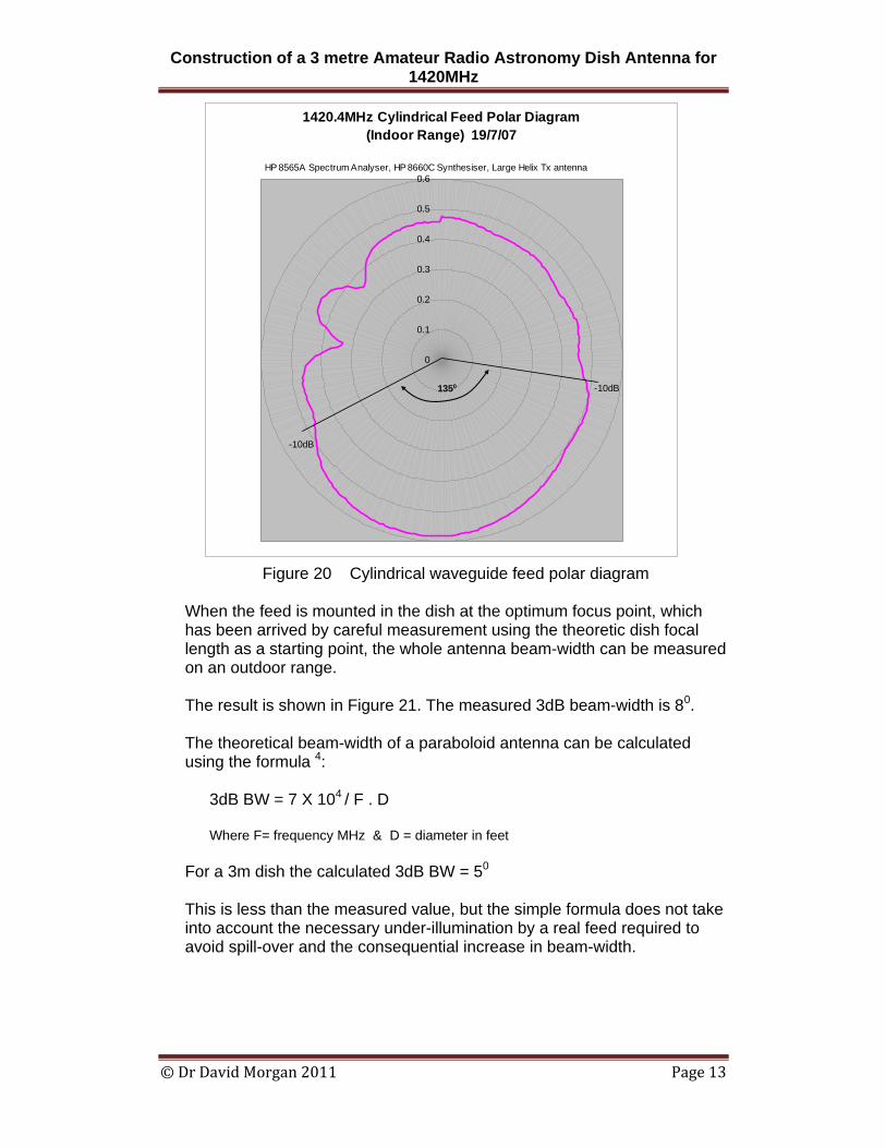
For the amateur radio astronomer a short focal length (deep) dish is a good solution, enabling the use of a simple low cost cylindrical feed that is well matched to the dish giving a reasonable gain and dish efficiency whilst minimising ground noise and interference. The feed polar diagram for the above dish was measured on an antenna range and is shown in Figure 20. The -10dB beam-width is 1350 , slightly less than the theoretical value of 1500 derived by calculation.
Construction of a 3 metre Amateur Radio Astronomy Dish Antenna for 1420MHz
© Dr David Morgan 2011 Page 13
Figure 20 Cylindrical waveguide feed polar diagram
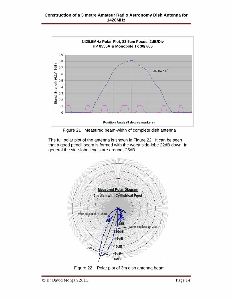
When the feed is mounted in the dish at the optimum focus point, which has been arrived by careful measurement using the theoretic dish focal length as a starting point, the whole antenna beam-width can be measured on an outdoor range. The result is shown in Figure 21. The measured 3dB beam-width is 80.
The theoretical beam-width of a paraboloid antenna can be calculated using the formula 4:
3dB BW = 7 X 10⁴ / F . D Where F= frequency MHz & D = diameter in feet
For a 3m dish the calculated 3dB BW = 50
This is less than the measured value, but the simple formula does not take into account the necessary under-illumination by a real feed required to avoid spill-over and the consequential increase in beam-width.
1420.4MHz Cylindrical Feed Polar Diagram (Indoor Range) 19/7/07
0
0.1
0.2
0.3
0.4
0.5
0.6
-10dB
-10dB1350
HP 8565A Spectrum Analyser, HP 8660C Synthesiser, Large Helix Tx antenna
Construction of a 3 metre Amateur Radio Astronomy Dish Antenna for 1420MHz
© Dr David Morgan 2011 Page 14
Figure 21 Measured beam-width of complete dish antenna
The full polar plot of the antenna is shown in Figure 22. It can be seen that a good pencil beam is formed with the worst side-lobe 22dB down. In general the side-lobe levels are around -25dB.
Figure 22 Polar plot of 3m dish antenna beam
1420.5MHz Polar Plot, 83.5cm Focus, 2dB/Div HP 8555A & Monopole Tx 30/7/06
0
0.1
0.2
0.3
0.4
0.5
0.6
0.7
0.8
0.9
1 12 23 34 45 56 67 78 89 100 111 122 133 144 155 166 177 188 199 210Position Angle (5 degree markers)
Sign
al S
tren
gth
(0.1
V=2d
B)
-3dB BW = 80
Construction of a 3 metre Amateur Radio Astronomy Dish Antenna for 1420MHz
© Dr David Morgan 2011 Page 15
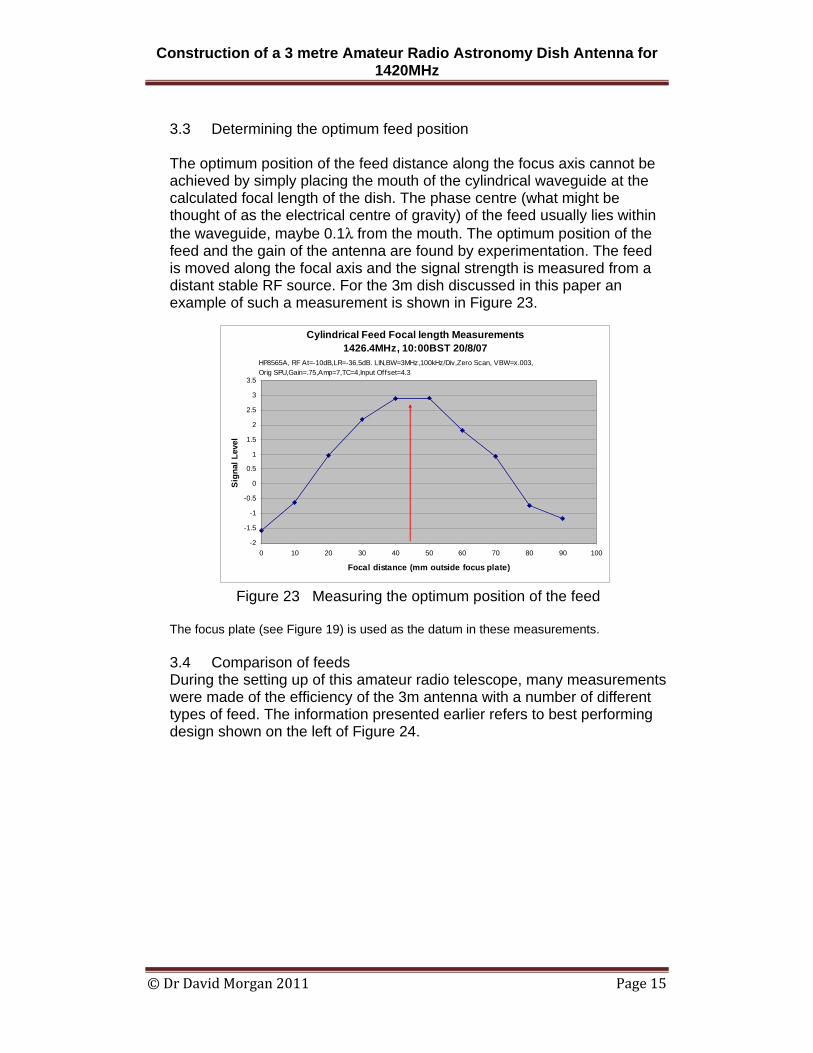
3.3 Determining the optimum feed position The optimum position of the feed distance along the focus axis cannot be achieved by simply placing the mouth of the cylindrical waveguide at the calculated focal length of the dish. The phase centre (what might be thought of as the electrical centre of gravity) of the feed usually lies within the waveguide, maybe 0.1λ from the mouth. The optimum position of the feed and the gain of the antenna are found by experimentation. The feed is moved along the focal axis and the signal strength is measured from a distant stable RF source. For the 3m dish discussed in this paper an example of such a measurement is shown in Figure 23.
Figure 23 Measuring the optimum position of the feed The focus plate (see Figure 19) is used as the datum in these measurements. 3.4 Comparison of feeds During the setting up of this amateur radio telescope, many measurements were made of the efficiency of the 3m antenna with a number of different types of feed. The information presented earlier refers to best performing design shown on the left of Figure 24.
Cylindrical Feed Focal length Measurements 1426.4MHz, 10:00BST 20/8/07
-2
-1.5
-1
-0.5
0
0.5
1
1.5
2
2.5
3
3.5
0 10 20 30 40 50 60 70 80 90 100
Focal distance (mm outside focus plate)
Sig
nal L
evel
HP8565A, RF At=-10dB,LR=-36.5dB. LIN,BW=3MHz,100kHz/Div,Zero Scan, VBW=x.003, Orig SPU,Gain=.75,Amp=7,TC=4,Input Offset=4.3
Construction of a 3 metre Amateur Radio Astronomy Dish Antenna for 1420MHz
© Dr David Morgan 2011 Page 16
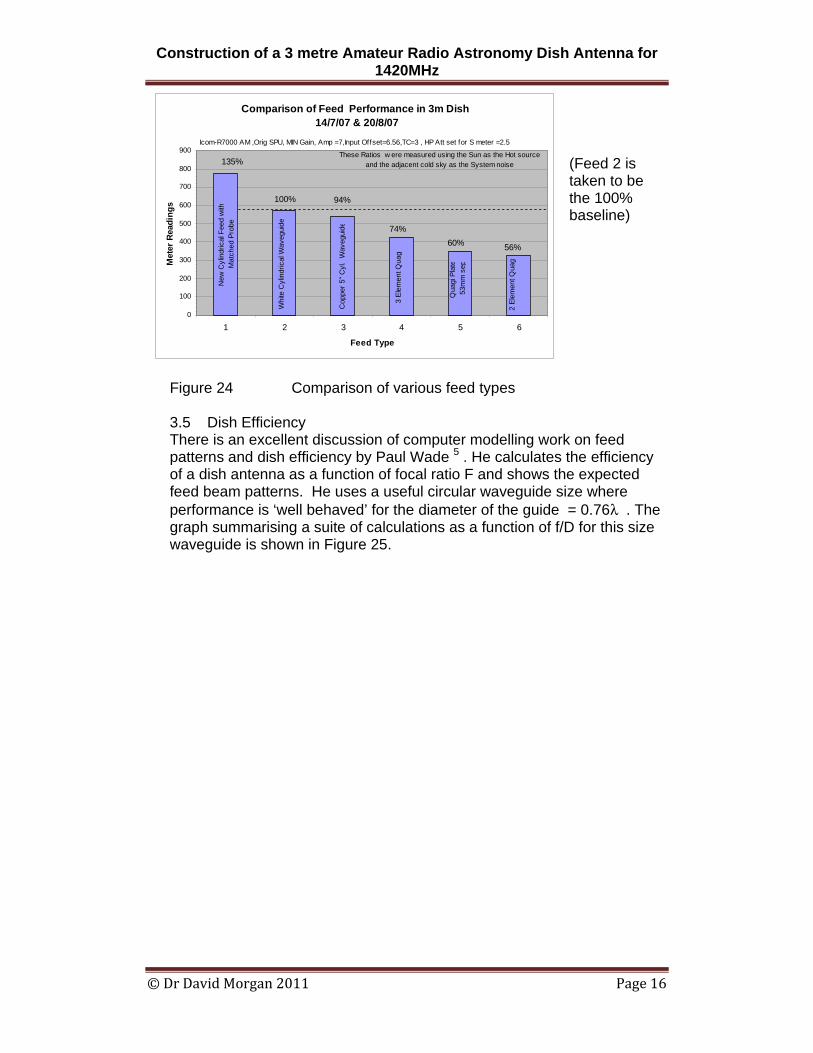
(Feed 2 is taken to be the 100% baseline)
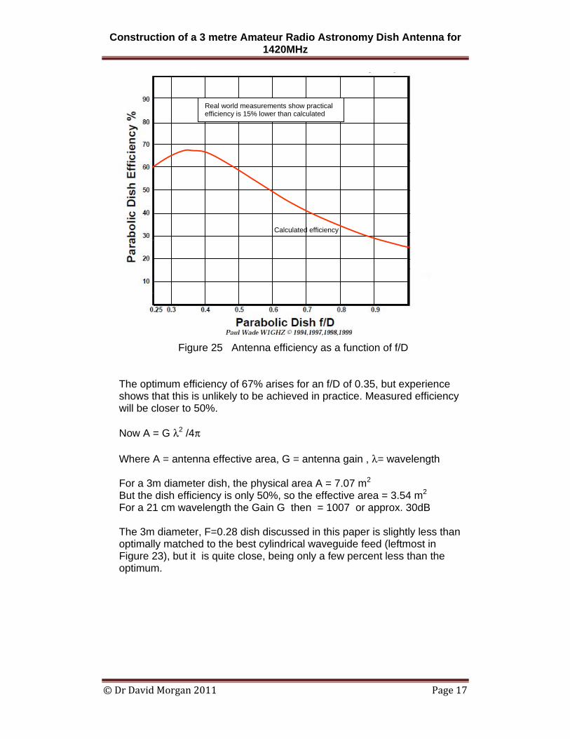
Figure 24 Comparison of various feed types 3.5 Dish Efficiency There is an excellent discussion of computer modelling work on feed patterns and dish efficiency by Paul Wade 5 . He calculates the efficiency of a dish antenna as a function of focal ratio F and shows the expected feed beam patterns. He uses a useful circular waveguide size where performance is ‘well behaved’ for the diameter of the guide = 0.76λ . The graph summarising a suite of calculations as a function of f/D for this size waveguide is shown in Figure 25.
Comparison of Feed Performance in 3m Dish 14/7/07 & 20/8/07
0
100
200
300
400
500
600
700
800
900
1 2 3 4 5 6
Feed Type
Met
er R
eadi
ngs
Whi
te C
ylin
dric
al W
aveg
uide
3 El
emen
t Qua
g
Qua
gi P
late
53m
m s
ep
2 El
emen
t Qua
g
74%60% 56%
These Ratios w ere measured using the Sun as the Hot source and the adjacent cold sky as the System noise
Icom-R7000 AM ,Orig SPU, MIN Gain, Amp =7,Input Offset=6.56,TC=3 , HP Att set for S meter =2.5
100%
135%
New
Cyl
indr
ical
Fee
d w
ithM
atch
ed P
robe
Cop
per 5
" Cyl
. W
aveg
uide
94%
Construction of a 3 metre Amateur Radio Astronomy Dish Antenna for 1420MHz
© Dr David Morgan 2011 Page 17
Figure 25 Antenna efficiency as a function of f/D
The optimum efficiency of 67% arises for an f/D of 0.35, but experience shows that this is unlikely to be achieved in practice. Measured efficiency will be closer to 50%. Now A = G λ2 /4π Where A = antenna effective area, G = antenna gain , λ= wavelength For a 3m diameter dish, the physical area A = 7.07 m2 But the dish efficiency is only 50%, so the effective area = 3.54 m2 For a 21 cm wavelength the Gain G then = 1007 or approx. 30dB The 3m diameter, F=0.28 dish discussed in this paper is slightly less than optimally matched to the best cylindrical waveguide feed (leftmost in Figure 23), but it is quite close, being only a few percent less than the optimum.
Real world measurements show practical efficiency is 15% lower than calculated
Calculated efficiency
Construction of a 3 metre Amateur Radio Astronomy Dish Antenna for 1420MHz
© Dr David Morgan 2011 Page 18
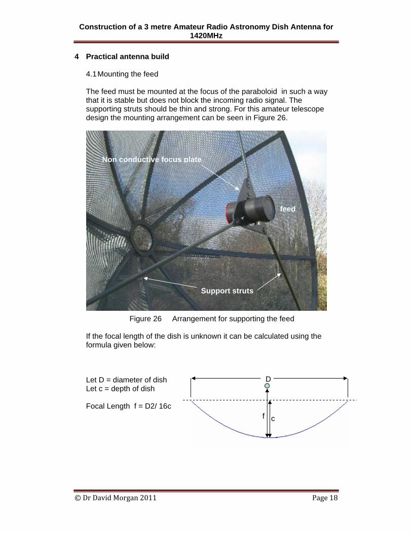
4 Practical antenna build 4.1 Mounting the feed The feed must be mounted at the focus of the paraboloid in such a way that it is stable but does not block the incoming radio signal. The supporting struts should be thin and strong. For this amateur telescope design the mounting arrangement can be seen in Figure 26.
Figure 26 Arrangement for supporting the feed
If the focal length of the dish is unknown it can be calculated using the formula given below: Let D = diameter of dish Let c = depth of dish Focal Length f = D2/ 16c
Non conductive focus plate
Support struts
feed
D
cf
Construction of a 3 metre Amateur Radio Astronomy Dish Antenna for 1420MHz
© Dr David Morgan 2011 Page 19
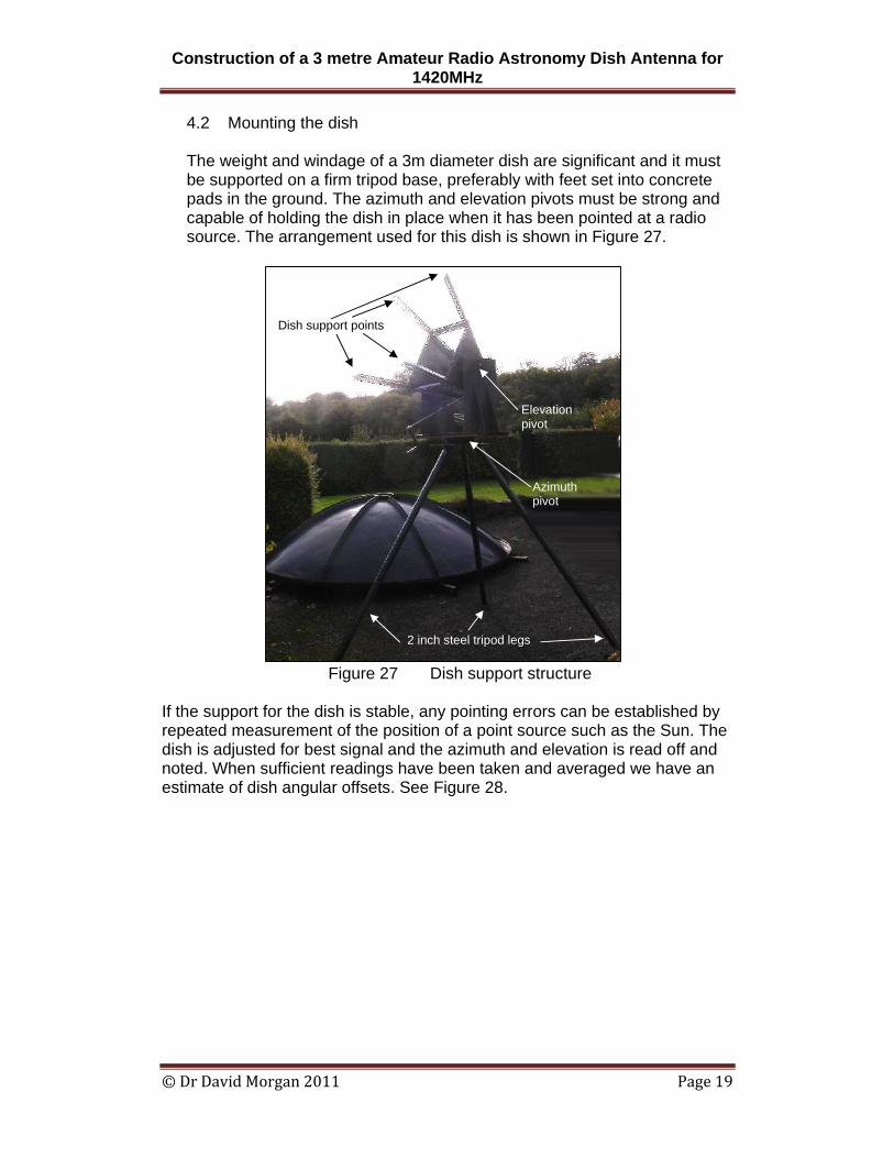
4.2 Mounting the dish The weight and windage of a 3m diameter dish are significant and it must be supported on a firm tripod base, preferably with feet set into concrete pads in the ground. The azimuth and elevation pivots must be strong and capable of holding the dish in place when it has been pointed at a radio source. The arrangement used for this dish is shown in Figure 27.
Figure 27 Dish support structure
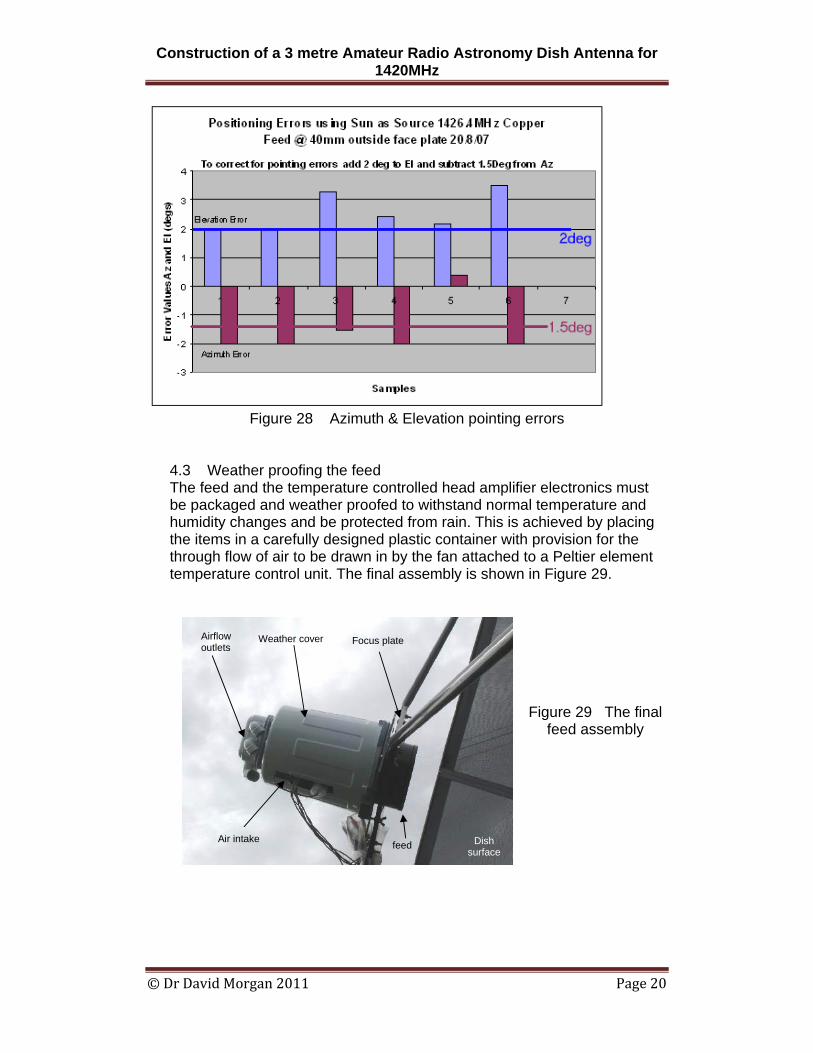
If the support for the dish is stable, any pointing errors can be established by repeated measurement of the position of a point source such as the Sun. The dish is adjusted for best signal and the azimuth and elevation is read off and noted. When sufficient readings have been taken and averaged we have an estimate of dish angular offsets. See Figure 28.
2 inch steel tripod legs
Azimuth pivot
Elevation pivot
Dish support points
Construction of a 3 metre Amateur Radio Astronomy Dish Antenna for 1420MHz
© Dr David Morgan 2011 Page 20
Figure 28 Azimuth & Elevation pointing errors
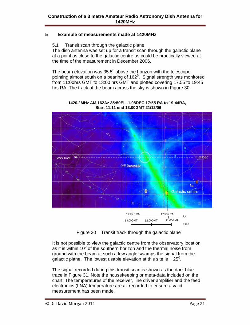
4.3 Weather proofing the feed The feed and the temperature controlled head amplifier electronics must be packaged and weather proofed to withstand normal temperature and humidity changes and be protected from rain. This is achieved by placing the items in a carefully designed plastic container with provision for the through flow of air to be drawn in by the fan attached to a Peltier element temperature control unit. The final assembly is shown in Figure 29.
Figure 29 The final feed assembly
Weather cover Airflow outlets
Air intake
Focus plate
feed Dish surface
Construction of a 3 metre Amateur Radio Astronomy Dish Antenna for 1420MHz
© Dr David Morgan 2011 Page 21
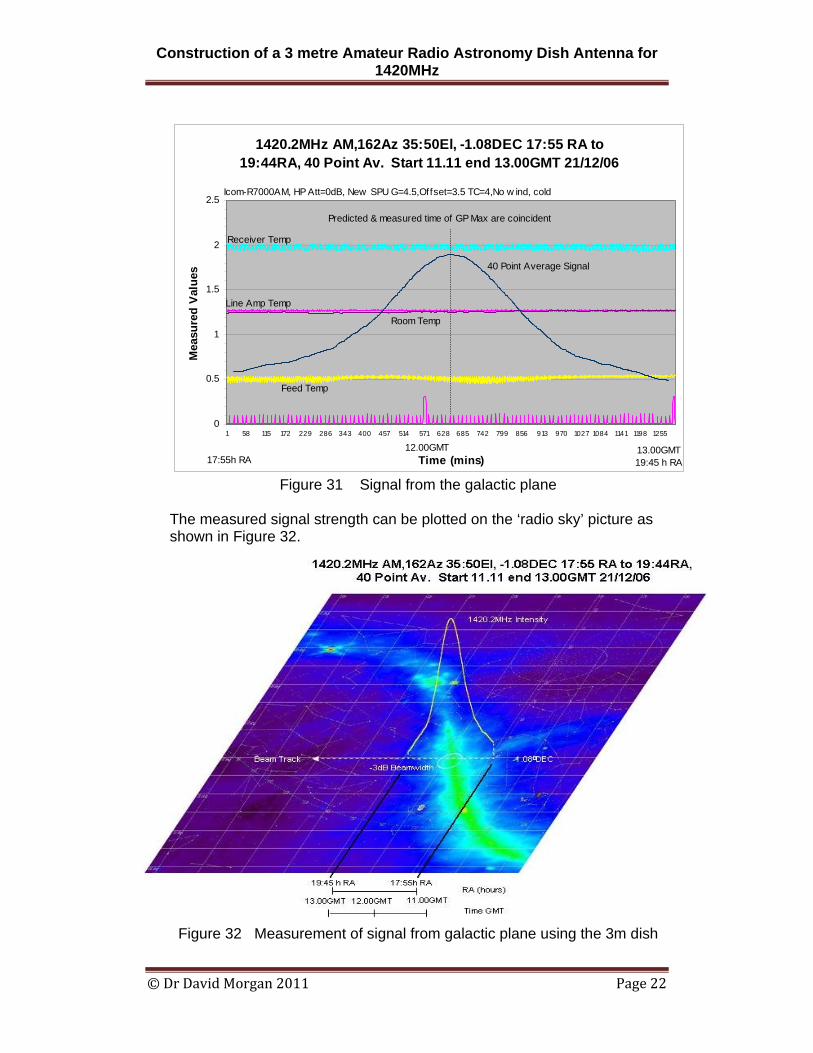
5 Example of measurements made at 1420MHz 5.1 Transit scan through the galactic plane The dish antenna was set up for a transit scan through the galactic plane at a point as close to the galactic centre as could be practically viewed at the time of the measurement in December 2006. The beam elevation was 35.50 above the horizon with the telescope pointing almost south on a bearing of 1620. Signal strength was monitored from 11:00hrs GMT to 13:00 hrs GMT and plotted covering 17.55 to 19:45 hrs RA. The track of the beam across the sky is shown in Figure 30.
Figure 30 Transit track through the galactic plane
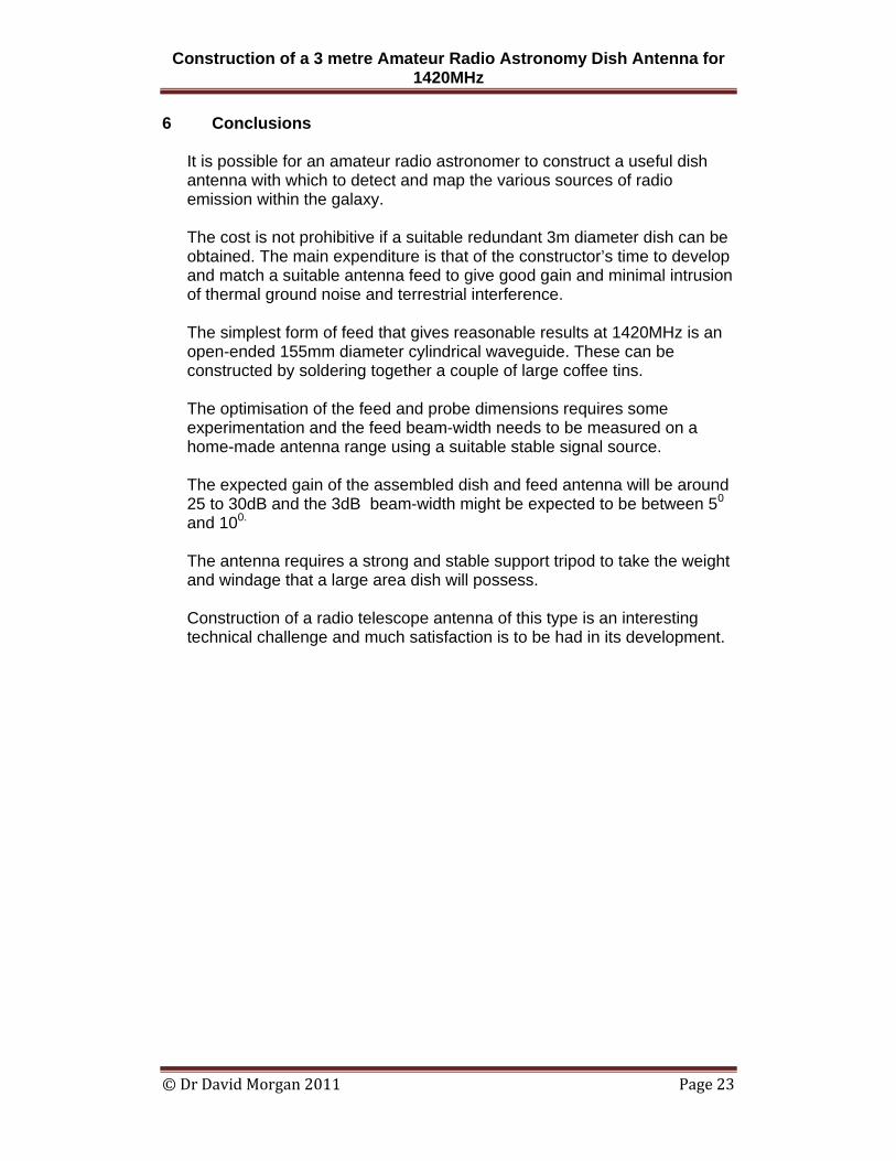
It is not possible to view the galactic centre from the observatory location as it is within 100 of the southern horizon and the thermal noise from ground with the beam at such a low angle swamps the signal from the galactic plane. The lowest usable elevation at this site is ~ 250. The signal recorded during this transit scan is shown as the dark blue trace in Figure 31. Note the housekeeping or meta-data included on the chart. The temperatures of the receiver, line driver amplifier and the feed electronics (LNA) temperature are all recorded to ensure a valid measurement has been made.
1420.2MHz AM,162Az 35:50El, -1.08DEC 17:55 RA to 19:44RA, Start 11.11 end 13.00GMT 21/12/06
13.00GMT 12.00GMT
17:55h RA 19:45 h RA
11.00GMT RA
Time Beam -0 C
Galactic centre
Construction of a 3 metre Amateur Radio Astronomy Dish Antenna for 1420MHz
© Dr David Morgan 2011 Page 22
1420.2MHz AM,162Az 35:50El, -1.08DEC 17:55 RA to 19:44RA, 40 Point Av. Start 11.11 end 13.00GMT 21/12/06
0
0.5
1
1.5
2
2.5
1 58 115 172 229 286 343 400 457 514 571 628 685 742 799 856 913 970 1027 1084 1141 1198 1255
Time (mins)
Mea
sure
d V
alue
s
13.00GMT
Receiver Temp
Line Amp Temp
Room Temp
Feed Temp
40 Point Average Signal
Icom-R7000AM, HP Att=0dB, New SPU G=4.5,Offset=3.5 TC=4,No w ind, cold
12.00GMT
Predicted & measured time of GP Max are coincident
17:55h RA 19:45 h RA Figure 31 Signal from the galactic plane
The measured signal strength can be plotted on the ‘radio sky’ picture as shown in Figure 32.
Figure 32 Measurement of signal from galactic plane using the 3m dish
Construction of a 3 metre Amateur Radio Astronomy Dish Antenna for 1420MHz
© Dr David Morgan 2011 Page 23
6 Conclusions
It is possible for an amateur radio astronomer to construct a useful dish antenna with which to detect and map the various sources of radio emission within the galaxy. The cost is not prohibitive if a suitable redundant 3m diameter dish can be obtained. The main expenditure is that of the constructor’s time to develop and match a suitable antenna feed to give good gain and minimal intrusion of thermal ground noise and terrestrial interference. The simplest form of feed that gives reasonable results at 1420MHz is an open-ended 155mm diameter cylindrical waveguide. These can be constructed by soldering together a couple of large coffee tins. The optimisation of the feed and probe dimensions requires some experimentation and the feed beam-width needs to be measured on a home-made antenna range using a suitable stable signal source. The expected gain of the assembled dish and feed antenna will be around 25 to 30dB and the 3dB beam-width might be expected to be between 50 and 100.
The antenna requires a strong and stable support tripod to take the weight and windage that a large area dish will possess. Construction of a radio telescope antenna of this type is an interesting technical challenge and much satisfaction is to be had in its development.
Construction of a 3 metre Amateur Radio Astronomy Dish Antenna for 1420MHz
© Dr David Morgan 2011 Page 24
Appendix A Coffee Can Feed
This information on how to build a basic coffee can feed can be found at: http:/www.bambi.net/sara/cliff.htm
A 1296 MHz horn is easy to make out of the trusty coffee can. Simply take two 36 ounce cans and solder the open ends together. This will take a large soldering gun. This produces a horn that is too long for the frequency, so we then cut the can very carefully with a very fine blade saw to a length of 10 1/8.". Be sure the cut is square to the bottom of the can. Don't use tin snips as they distort the metal too much. The probe is made out of #14 solid wire 2.128" long, soldered to a female "N" type chassis connector. From the bottom end of the can measure out 2 3/4" and lightly centre-punch the mark. Drill a hole 3/16 in diameter and place the chassis connector, probe end first , in the hole. Drill the little screw mounting holes. I use very small sheet metal screws. Keep screw length to a minimum inside the can. The wire probe picks up the signal.
References 1. John Fielding Amateur Radio Astronomy, RSGB publications 2. Samuel Silver Microwave Antenna Theory and Design, IEE EM waves series. 10.4 3. http://www.rfcafe.com/references/electrical/circular-waveguide-modes.htm 4. David Morgan A handbook for EMC testing & Measurement IEE Elec. Measurement
Series 8 p 104 5. Paul Wade W1GHZ Microwave Antenna handbook Feeds for Parabolic Dish
Antennas Chapter 6