Construction of a Multilevel Container · PDF fileConstruction of a Multilevel Container...
19
① ② ③ ④ Construction of a Multilevel Container Warehouse Objective: To strengthen terminal functions to meet the increase in cargo • Increases container capacity in a limited amount of space • Also contributes to reduced CO 2 emissions and enhanced convenience (reduces waiting time for trucks picking up containers) Overview: Multilevel container warehouse Start of operations: April 2011 Facility specs Length: Approx. 150m Width: Approx. 56m Height: Approx. 31m Maximum capacity: 840 TEU (All levels equipped with reefer outlets) Maximum processing capability: 48 containers/hour Attached facility: Solar power generation system (200kW) Facility’s effectiveness • Containers can be loaded/unloaded from any location resulting in an approx. 30 percent improvement in efficiency over use of general handling systems. • With seven levels of container racks, storage capacity is increased approx. 70 percent over a storage yard. • Through the use of commercial electric power, CO 2 emissions are reduced approx. 60 percent over the use of diesel fuel. Details: How containers are moved from the warehouse to trucks ① Using a dolly, a container is removed from the container rack. ② The container removed is transferred to the turntable by the stacker crane. ③ On the turntable, the container is rotated 90 degrees. ④ The overhead crane then mounts the container on the chassis. 37 Infrastructure Disaster prevention Environment Health, Industry Port and Harbor Bureau of Port and Harbor No. 16 90m 56m 50m 31m 150m Overhead crane Container rack Overhead crane Stacker crane with dolly Turntable Turntable Solar panel
-
Upload
hoangquynh -
Category
Documents
-
view
221 -
download
1
Transcript of Construction of a Multilevel Container · PDF fileConstruction of a Multilevel Container...

①
②
③④
Construction of a Multilevel Container WarehouseObjective: To strengthen terminal functions to meet the increase in cargo
• Increases container capacity in a limited amount of space• Also contributes to reduced CO2 emissions and enhanced convenience (reduces waiting time for trucks
picking up containers)
Overview: Multilevel container warehouseStart of operations: April 2011Facility specs
Length: Approx. 150m Width: Approx. 56mHeight: Approx. 31m
Maximum capacity: 840 TEU(All levels equipped with reefer outlets)
Maximum processing capability: 48 containers/hourAttached facility: Solar power generation system (200kW)
Facility’s effectiveness• Containers can be loaded/unloaded from any location resulting in an approx. 30 percent improvement in
efficiency over use of general handling systems. • With seven levels of container racks, storage capacity is increased approx. 70 percent over a storage yard.• Through the use of commercial electric power, CO2 emissions are reduced approx. 60 percent over the use of
diesel fuel.
Details: How containers are moved from the warehouse to trucks① Using a dolly, a container is removed from the container
rack.② The container removed is transferred to the turntable by the
stacker crane.③ On the turntable, the container is rotated 90 degrees.④The overhead crane then mounts the container on the chassis.
37
InfrastructureD
isaster preventionEnvironm
entH
ealth, IndustryPort and Harbor Bureau of Port and Harbor No. 16
90m
56m
50m
31m
150m
Overhead crane
Container rack
Overheadcrane
Stacker crane with dolly
Turntable
Turntable
Solar panel

Redevelopment of Existing Container Terminals
Objective: To achieve high-standard terminals by using existing facilities• Greatly improve functions of the existing container terminals while they are in service• Reduce and even out life cycle costs through a preventive maintenance program
Overview: Example of a redevelopment project (1996 to 2003)
Details: Redevelopment and introduction of preventive maintenance
39
InfrastructureD
isaster preventionEnvironm
entH
ealth, IndustryPort and Harbor Bureau of Port and Harbor No. 17
• Early detection of areas in need of repair and steady implementation of systematic repairs
Anticorrosion measures including cross-section repair, surface coating, and electric anticorrosion
Projects to be carried out in sequence while port operations continue Preventive Maintenance
• Projects were carried out while keeping six berths in service at all times.
Visual inspection of piers
Repairing by electric anticorrosion
(Weight of Steel Formwork 32.8t)
Aogashima Harbor
Vertical Joint
Foundation Concrete Mound
Anchor
Place of construction
Steel Formwork Construction Method for Port and Harbor Construction under Harsh Conditions
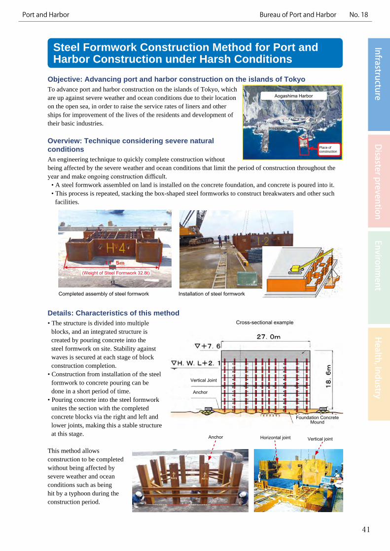
Objective: Advancing port and harbor construction on the islands of TokyoTo advance port and harbor construction on the islands of Tokyo, which are up against severe weather and ocean conditions due to their location on the open sea, in order to raise the service rates of liners and other ships for improvement of the lives of the residents and development of their basic industries.
Overview: Technique considering severe natural conditionsAn engineering technique to quickly complete construction without being affected by the severe weather and ocean conditions that limit the period of construction throughout the year and make ongoing construction difficult.
• A steel formwork assembled on land is installed on the concrete foundation, and concrete is poured into it. • This process is repeated, stacking the box-shaped steel formworks to construct breakwaters and other such
facilities.
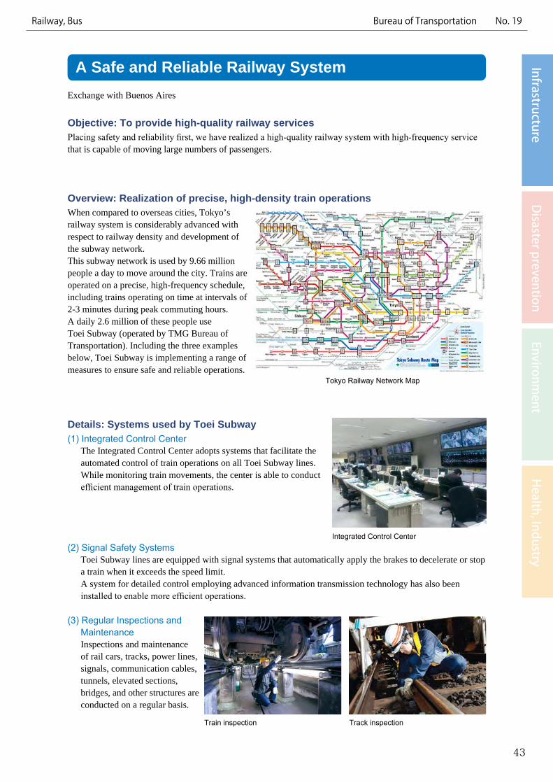
Details: Characteristics of this method• The structure is divided into multiple
blocks, and an integrated structure is created by pouring concrete into the steel formwork on site. Stability against waves is secured at each stage of block construction completion.
• Construction from installation of the steel formwork to concrete pouring can be done in a short period of time.
• Pouring concrete into the steel formwork unites the section with the completed concrete blocks via the right and left and lower joints, making this a stable structure at this stage.
This method allows construction to be completed without being affected by severe weather and ocean conditions such as being hit by a typhoon during the construction period.
41
InfrastructureD
isaster preventionEnvironm
entH
ealth, IndustryPort and Harbor Bureau of Port and Harbor No. 18
Anchor Horizontal joint Vertical joint
Cross-sectional example
Completed assembly of steel formwork Installation of steel formwork
A Safe and Reliable Railway SystemExchange with Buenos Aires
Objective: To provide high-quality railway servicesPlacing safety and reliability first, we have realized a high-quality railway system with high-frequency service that is capable of moving large numbers of passengers.
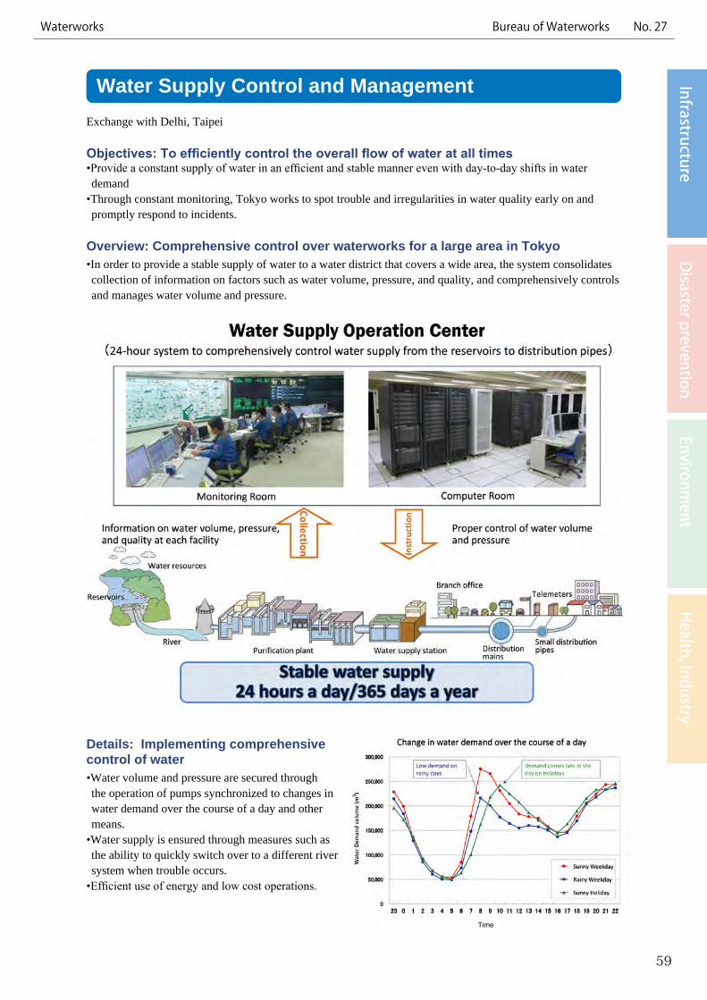
Overview: Realization of precise, high-density train operationsWhen compared to overseas cities, Tokyo’s railway system is considerably advanced with respect to railway density and development of the subway network.This subway network is used by 9.66 million people a day to move around the city. Trains are operated on a precise, high-frequency schedule, including trains operating on time at intervals of 2-3 minutes during peak commuting hours.A daily 2.6 million of these people use Toei Subway (operated by TMG Bureau of Transportation). Including the three examples below, Toei Subway is implementing a range of measures to ensure safe and reliable operations.
Details: Systems used by Toei Subway(1) Integrated Control Center
The Integrated Control Center adopts systems that facilitate the automated control of train operations on all Toei Subway lines. While monitoring train movements, the center is able to conduct efficient management of train operations.
(2) Signal Safety SystemsToei Subway lines are equipped with signal systems that automatically apply the brakes to decelerate or stop a train when it exceeds the speed limit.A system for detailed control employing advanced information transmission technology has also been installed to enable more efficient operations.
(3) Regular Inspections and MaintenanceInspections and maintenance of rail cars, tracks, power lines, signals, communication cables, tunnels, elevated sections, bridges, and other structures are conducted on a regular basis.
43
InfrastructureD
isaster preventionEnvironm
entH
ealth, IndustryRailway, Bus Bureau of Transportation No. 19
Tokyo Railway Network Map
Integrated Control Center
Train inspection Track inspection

Pantograph Pantograph
Transformer
EscalatorRectifier
Regenerativeinverter
Braking
Electrical substation Station
LightsA/C and ventilation
Overheadlines
Running
Electric Power Regeneration SystemObjective: Effective energy useThrough the adoption of an electric power regeneration system, Toei Subway aims to make the railway more energy efficient.
Overview:• Trains consume a great deal of electricity when they accelerate. With the installation of an electric power
regeneration system, however, power generated when trains decelerate can be used, making railways more energy efficient.
• This is an energy efficient technology widely used by Japanese railway companies, and it is one of the technologies expected to make further growth abroad.
Details: How the electric power regeneration system works• An electric power regeneration system is a regenerative braking system. By using the motor that powers the
train as a generator when the brakes are applied, some of the kinetic energy that would otherwise be lost to heat can be converted to electric power and reused.
• This electricity is transferred to the overhead lines via the train’s pantographs (see below) and either used to power other trains, or sent to a power substation and used to power lights and escalators in subway stations.
45
InfrastructureD
isaster preventionEnvironm
entH
ealth, IndustryRailway, Bus Bureau of Transportation No. 20
Blue line: Commercial powerOrange line: Regenerated electricity
How the electric power regeneration system works

Crack occurring from water leakage
Syringe
Stop the leak by drilling into the crack and injecting a sealant
Systematic Repair of Subway TunnelsObjective: To secure safety of subway structures from a long-term perspective•To secure facility safety while also ensuring the regular operation of trains by implementing planned
maintenance and management of aging subway structures constructed several dozen years ago from a long-term perspective based on site inspections and application of the PDCA cycle.
Overview: Systematic repair based on inspections•Systematic repair is implemented by grasping the situation
through detailed inspection results and changes. •Continuous and spherical imaging in the tunnel is
implemented and a database is built by adding data such as inspection and construction information.
•Inspections continue to be conducted after the repairs have been made and repair plans are revised accordingly.
Details: Specific contents of repair•Implementation of measures against exfoliation, water leakage, neutralization, and other problems.•Notably, measures against water leaks (waterproofing of tunnel walls), which are a key cause of structure
deterioration, have been bolstered by expanding construction scale.
Water leak Schematic drawing of water leak measure
*PDCA (Plan-Do-Check-Act) cycle is used for systematic repair based on inspections. The efficacy of the methodology is always verified and reflected in the next repair work and inspection methodology.
47
InfrastructureD
isaster preventionEnvironm
entH
ealth, IndustryRailway, Bus Bureau of Transportation No. 21
Inspection by sounding concrete

Training and Preparedness for Toei Subway Safety Exchange with New Taipei
Objective: To maintain and improve emergency response capabilitiesAlong with making the capital investment needed to ensure safety, public transportation services must also be fully prepared to provide a prompt response in the unlikely event of an accident or disaster. As such, transportation providers conduct drills based on a variety of scenarios with the aim of maintaining and enhancing emergency response capabilities.
Overview: Comprehensive drills for a large-scale disaster or accidentIn addition to each office independently conducting routine training, joint comprehensive drills that simulate large-scale disasters and emergencies are conducted on a regular basis through the cooperation of various offices.
Details: Types of training drills(1) Comprehensive Emergency Drill
Based on an emergency scenario, this is a large-scale, practical training exercise held annually since 1970, in which staff practice train protection, evacuation of passengers, rescue support, communications, derailment recovery, and restoration of facilities.
(2) Natural Disaster Preparedness DrillThis large-scale drill, which simulates floodwater entering a station through the station entrances/exits due to a torrential downpour, has been held annually since 1990.In addition, each station holds drills for flood prevention.
(3) NBC (Nuclear Biological Chemical) DrillThis drill, conducted with the police and fire departments, prepares staff to lead evacuations in the event of dispersion of chemicals, and to detect, collect, and remove suspicious objects.
(4) Drill for the Evacuation and Accommodation of Stranded Commuters and Others
This drill simulates what will occur when many people become stranded due to the suspension of train services following a major earthquake directly striking Tokyo. Exercises to lead passengers to safety and distribute emergency supplies to those stranded at temporary accommodation sites are held.
49
InfrastructureD
isaster preventionEnvironm
entH
ealth, IndustryRailway, Bus Bureau of Transportation No. 22
Comprehensive emergency drill
Natural disaster preparedness drill
NBC drill Drill for the evacuation and accommodation ofstranded commuters and others

Operation of AGT (Automated Guideway Transit) SystemsObjective: To introduce a new means of transportation to built-up areasIt is possible to introduce this system in existing built-up areas without any need to purchase large pieces of land. Through the development of public transportation that has greater capacity than buses, a form of transportation that is safe, runs on time, and is not affected by traffic congestion is realized.
Overview: Medium-capacity rail transport system• Constructing support pillars on median strips
and special rails on top of those pillars allows the use of space above roads. At approx. 7-12 billion yen/double track km*, the cost is more reasonable than that of subway lines (approx. 25-35 billion yen/double track km*).
• It is possible to have the tracks curve at intersections, and this system can be introduced in redevelopment plans that make use of the existing cityscape.
• The systems are driverless. When there is the need to run extra trains to meet an increase in demand due to an event, etc., operation of the system will not be restricted by the number of drivers available.
*Source: Survey on the Introduction of Light Rail Transit Integrated with City Planning, March 2010, Institution for Transport Policy Studies
Details(1) Driverless trains
1. ATO (Automatic Train Operation) controls operations such as running and stopping the train, opening and closing doors at stations, and train departure.
2. Speed control is achieved through ATC (Automatic Train Control). The system sends train signals to control speed based on conditions such as the distance between trains.
3. Both ATO and ATC are dual systems to ensure the safe operation of trains.
(2) Train car characteristics 1. The cars are compact in comparison to railway
cars, and run on rubber tires.2. The train’s minimum curve radius is 30m (45m within the operating area), and steepest gradient is 60% (50%
within the operating area).(3) Station characteristics
1. At stations with no attendants, intercoms and security cameras are installed throughout the station, and customer service is handled collectively by the control center.
2. Full-length platform doors are installed at all stations to prevent passengers from making accidental contact with trains or falling onto the tracks.
51
InfrastructureD
isaster preventionEnvironm
entH
ealth, IndustryBureau of Port and Harbor No. 23Railway, Bus

Bus Location SystemExchange with Gansu province (China)
Objective: To provide detailed information on bus operationsWith the aim to enhance services, the system distributes detailed information on bus operations such as the location of approaching buses and the estimated amount of time required to reach a destination.
Overview: Provision of information on Toei Bus operations collected by GPS• Data on the location of Toei buses (operated by the TMG Bureau of Transportation) is collected using GPS
and other systems, and then shared with users through information terminals such as display panels at bus stops, mobile phones, and computers.
• Other services are also provided for these devices, including a search function that displays bus stops on a map, an application that guides users of GPS-equipped mobile phones to the nearest bus stop, and a Toei Transportation route search function.
Details: Specific technology utilizedInformation on bus operations is transmitted by linking the following six systems.
53
InfrastructureD
isaster preventionEnvironm
entH
ealth, IndustryBureau of Transportation No. 24Railway, Bus

Technology for Non-Revenue Water (NRW) ReductionExchange with Bangkok, Taipei, Yangon, Delhi
Objective: To reduce NRW, which is essential for the sound management of water utilitiesThrough technologies to reduce NRW, Tokyo works to achieve effective use of precious water resources, reduce environmental impact, and improve the efficiency of operations.
Overview: Leakage prevention technology to reduce NRWTokyo Waterworks has actively promoted leakage prevention measures, and has reduced the percentage of NRW to just 3 percent.
Details:(1) Replacement of water pipes and improvements in materialsPreventive measures are taken to prevent water leakage before it happens, as well as to eliminate any existing underground leakage.
(2) Methods of effectively finding and repairing leakage • Scheduled work to detect and repair underground leakage early on. (Implementation of planned leakage tests by district.)• Mobile emergency work to promptly repair leakages that appear above ground. (A system capable of 24/7
response has been built.)
(3) Development of advanced technologies to prevent leakage
55
InfrastructureD
isaster preventionEnvironm
entH
ealth, IndustryWaterworks Bureau of Waterworks No. 25
House A
Private
road
Public road
Service pipe (P
VC
pipe)
Distribution pipe (Ductile cast iron pipe)
House D
○ Water meter
House E
House B
House C
A
House A
Public road
Distribution pipe
Drain
Distribution pipe (Ductile cast iron pipe)
House D
○ Water meter
House E
House B
House C
整備後
Service pipe(Stainlesssteel pipe)
Private
road
Replacement of old pipes
Introduction of stainless steel service pipes
<Instruments used to detect leakage>Leakage sound detection bar
<Time integral type leakage detector>Instrument that automatically detects leakage
<Correlative leakage detector>Instrument that isolates the location of leakage
Upgrading service pipes
Public road area Public road area
Lead service pipe Stainless steel pipe
Private land Private land
Electronic leakagedetector

Water Purification Technology & Water Quality Management System
Exchange with Taipei
Objective: To supply potable and delicious tap waterTo improve public health and the living environment by supplying potable and delicious tap water.
Overview: Technology and system capable of accommodating all water resourcesWater purification technology and a water quality management system for water from all kinds of water sources such as river water, lake water, and ground water.
Details: (1) Water purification technology currently used by Tokyo WaterworksRapid sand filtration, advanced water treatment*, slow sand filtration, membrane filtration, deferrization/demanganization, aeration, etc.*Advanced water treatment is water purification with the objective of removing matter that cannot be removed
through regular treatment.
<Mechanism of Advanced Water Treatment>
(2) Comprehensive Water Quality Management System Water quality from water resources to the taps is managed comprehensively in order to supply high quality tap water.
57
InfrastructureD
isaster preventionEnvironm
entH
ealth, IndustryWaterworks Bureau of Waterworks No. 26
Time
Water Supply Control and ManagementExchange with Delhi, Taipei
Objectives: To efficiently control the overall flow of water at all times•Provide a constant supply of water in an efficient and stable manner even with day-to-day shifts in water demand
•Through constant monitoring, Tokyo works to spot trouble and irregularities in water quality early on and promptly respond to incidents.
Overview: Comprehensive control over waterworks for a large area in Tokyo•In order to provide a stable supply of water to a water district that covers a wide area, the system consolidates collection of information on factors such as water volume, pressure, and quality, and comprehensively controls and manages water volume and pressure.
Details: Implementing comprehensive control of water•Water volume and pressure are secured through the operation of pumps synchronized to changes in water demand over the course of a day and other means.
•Water supply is ensured through measures such as the ability to quickly switch over to a different river system when trouble occurs.
•Efficient use of energy and low cost operations.
59
InfrastructureD
isaster preventionEnvironm
entH
ealth, IndustryWaterworks Bureau of Waterworks No. 27
Catches and does not uncouple
Robust Water SystemExchange with Taipei
Objective: To build a robust water system in preparation for disasters and accidentsTo minimize damages to water facilities in the event of a disaster or accident, and secure water supply to all possible extent.
Overview: Bolster backup functions and earthquake resilienceAlong with bolstering backup functions in the event of an accident through the duplexing and networking of pipelines, efficient earthquake resistance of the water supply system will be implemented to prepare for disasters.
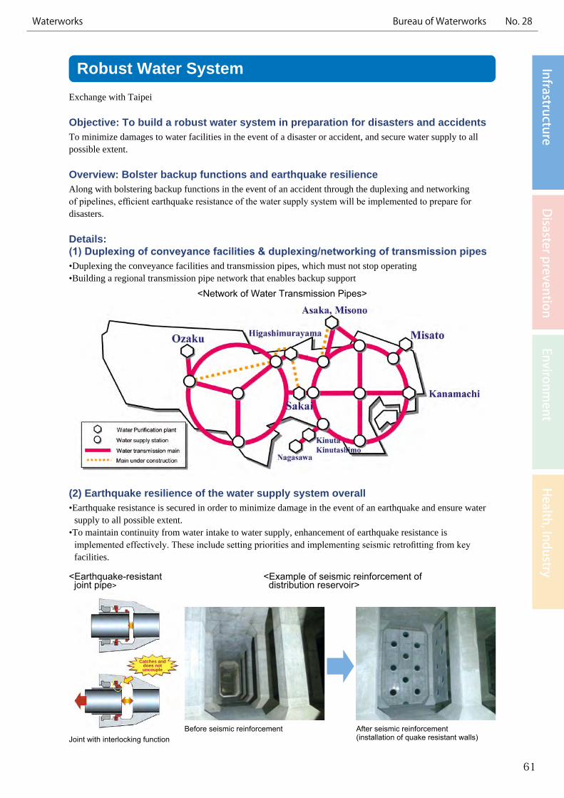
Details: (1) Duplexing of conveyance facilities & duplexing/networking of transmission pipes•Duplexing the conveyance facilities and transmission pipes, which must not stop operating•Building a regional transmission pipe network that enables backup support
<Network of Water Transmission Pipes>
(2) Earthquake resilience of the water supply system overall•Earthquake resistance is secured in order to minimize damage in the event of an earthquake and ensure water
supply to all possible extent. •To maintain continuity from water intake to water supply, enhancement of earthquake resistance is
implemented effectively. These include setting priorities and implementing seismic retrofitting from key facilities.
61
InfrastructureD
isaster preventionEnvironm
entH
ealth, IndustryWaterworks Bureau of Waterworks No. 28
Joint with interlocking functionBefore seismic reinforcement After seismic reinforcement
(installation of quake resistant walls)
<Earthquake-resistant joint pipe>
<Example of seismic reinforcement of distribution reservoir>
Storage of Water for Tokyo’s Water Supply
Objective: To secure stable water resourcesTo secure stable water resources capable of handling seasonal changes in precipitation and shifts in water demand
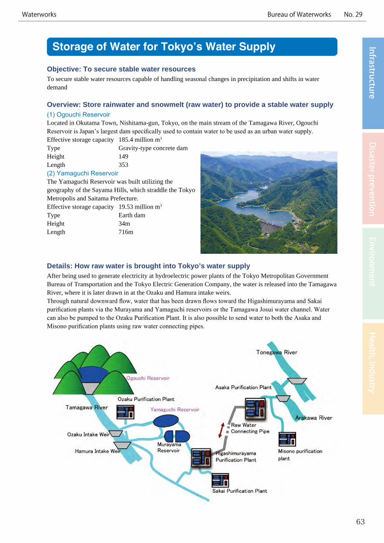
Overview: Store rainwater and snowmelt (raw water) to provide a stable water supply(1) Ogouchi ReservoirLocated in Okutama Town, Nishitama-gun, Tokyo, on the main stream of the Tamagawa River, Ogouchi Reservoir is Japan’s largest dam specifically used to contain water to be used as an urban water supply.Effective storage capacity 185.4 million m3
Type Gravity-type concrete damHeight 149 Length 353 (2) Yamaguchi ReservoirThe Yamaguchi Reservoir was built utilizing the geography of the Sayama Hills, which straddle the Tokyo Metropolis and Saitama Prefecture.Effective storage capacity 19.53 million m3
Type Earth damHeight 34mLength 716m
Details: How raw water is brought into Tokyo’s water supplyAfter being used to generate electricity at hydroelectric power plants of the Tokyo Metropolitan Government Bureau of Transportation and the Tokyo Electric Generation Company, the water is released into the Tamagawa River, where it is later drawn in at the Ozaku and Hamura intake weirs.Through natural downward flow, water that has been drawn flows toward the Higashimurayama and Sakai purification plants via the Murayama and Yamaguchi reservoirs or the Tamagawa Josui water channel. Water can also be pumped to the Ozaku Purification Plant. It is also possible to send water to both the Asaka and Misono purification plants using raw water connecting pipes.
63
InfrastructureD
isaster preventionEnvironm
entH
ealth, IndustryWaterworks Bureau of Waterworks No. 29
Consolidation of Wastewater and Sludge TreatmentFacilities
Exchange with Malaysia (Langat area)
Objective: To provide a reliable wastewater treatment system and improved water environmentMore efficient wastewater treatment by consolidating wastewater treatment and sludge treatment facilities will make reliable wastewater treatment possible and improve the area’s water environment.
Overview: Efficient treatment of wastewater and sludgeAbolishing existing, small wastewater treatment facilities, laying an extensive network of sewer pipes, and consolidating wastewater and sludge treatment processes at a large-scale wastewater treatment facility, will make efficient and reliable treatment possible, including savings in personnel and maintenance costs.
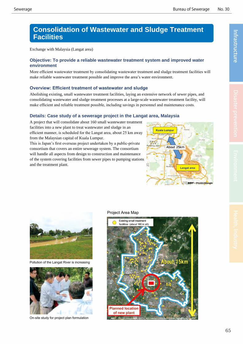
Details: Case study of a sewerage project in the Langat area, MalaysiaA project that will consolidate about 160 small wastewater treatment facilities into a new plant to treat wastewater and sludge in an efficient manner, is scheduled for the Langat area, about 25 km away from the Malaysian capital of Kuala Lumpur.This is Japan’s first overseas project undertaken by a public-private consortium that covers an entire sewerage system. The consortium will handle all aspects from design to construction and maintenance of the system covering facilities from sewer pipes to pumping stations and the treatment plant.
65
InfrastructureD
isaster preventionEnvironm
entH
ealth, IndustrySewerage Bureau of Sewerage No. 30
Pollution of the Langat River is increasing
On-site study for project plan formulation
Project Area Map

Deep Reaction Tank for Compact Wastewater Treatment Facilities
Exchange with Malaysia (Langat area)
Objective: To secure sufficient treatment capacity even on small sitesUsing a reaction tank that is deeper than conventional tanks makes it possible to build a wastewater treatment facility with sufficient capacity even on a small site.
Overview: Small footprint with twice the depthTreatment of large volumes of wastewater requires an expansive water reclamation center site. In a congested city like Tokyo, however, it is not easy to secure such a large space. Using a deep reaction tank with twice the depth of a conventional tank makes it possible to build a facility on an area half the size.
Details: Characteristics of the deep reaction tank• The deep reaction tank developed by the TMG can efficiently remove pollutants from sewage, thus
contributing to the improvement of water quality.• This technology is slated to be adopted for the sewerage system project in Malaysia’s Langat area, as only a
small area is available for the treatment plant.
67
InfrastructureD
isaster preventionEnvironm
entH
ealth, IndustrySewerage Bureau of Sewerage No. 31
Conventional reaction tank Deep reaction tank
Half the space, twice the depth
Air diffuser
Example of reaction tank

Sewer Rehabilitation MethodExchange with Singapore, South Korea, the United States, etc.
Objective: Reinforcing aged sewers from the inside without the need to rip up streetsSewerage services in Tokyo’s 23 wards started in the 1880s, and coverage reached nearly 100% (over 99.5%) in 1995. However, sewers installed in the early stages are aging. The Bureau of Sewerage is therefore promoting reconstruction of its sewers using a rehabilitation method that reinforces pipes from the inside, without the need to rip up streets.
Overview: Sewer rehabilitation by lining the inside of sewer pipesThis method rehabilitates existing sewers by lining the inside of the sewer pipe. Because trunk sewers are large sewers that form the backbone of the sewer network, collecting and sending large volumes of sewage downstream to pumping stations and water reclamation centers, etc., this method is taken to reinforce them from the inside without digging up the road.
Details: Example of rehabilitation method provided overseasThis method can be used even in sewers in service, and can be applied in pipes with various cross sections, including circular, horseshoe and rectangular shapes.
69
InfrastructureD
isaster preventionEnvironm
entH
ealth, IndustrySewerage Bureau of Sewerage No. 32
Sewer before reconstruction Sewer under reconstruction
The strength of the sewer has been reduced due to deterioration of the concrete surface and corrosion of reinforcement steel.
Reconstruction work inside a circular-shaped sewer
The sewer is lined with rigid polyvinyl chloride material to strengthen it. This enables low-cost and quick renewal since the streets do not have to be ripped up.
Preventing Flow of Debris into Rivers during RainExchange with Europe, Korea, and the United States
Objective: To alleviate pollution load on the riversDebris and white solids from combined sewer systems could flow into rivers during rain, increasing the pollution load on the rivers. With the aim to improve the water quality of rivers and the sea, the Tokyo Metropolitan Government has installed water surface control devices to prevent the flow of debris into the rivers.
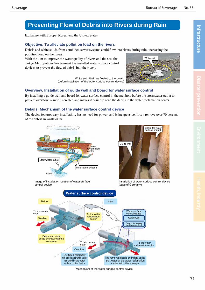
Overview: Installation of guide wall and board for water surface controlBy installing a guide wall and board for water surface control in the manhole before the stormwater outlet to prevent overflow, a swirl is created and makes it easier to send the debris to the water reclamation center.
Details: Mechanism of the water surface control deviceThe device features easy installation, has no need for power, and is inexpensive. It can remove over 70 percent of the debris in wastewater.
71
InfrastructureD
isaster preventionEnvironm
entH
ealth, IndustrySewerage Bureau of Sewerage No. 33
Image of installation location of water surface control device
Mechanism of the water surface control device
Installation of water surface control device(case of Germany)
To water reclamation center
Sewage
Rivers
RainwaterGuide wall
Board for water surface control
Stormwater outlet
Installation location
White solid
Before
Debris and white solids overflow with the
stormwater
Overflow of stormwater with debris and white solids
removed by the water surface control device
The removed debris and white solids are treated at the water reclamation
center with other sewage
OverflowTo the water reclamation
center
After
Guide wall
Water surface control device
Board for water surface control
To the water reclamation center
Overflow
To stormwater outlet
To stormwater outlet
White solid that has floated to the beach(before installation of the water surface control device)
Water surface control device
Sewerage Technology Training CenterExchange with Brazil, Vietnam, etc.
Objective: To train personnel in the sewerage field and pass on technologiesThrough the process of experiencing operations first hand, including training in a variety of areas, such as civil engineering, machinery, electrical systems, and water quality management, and simulations, the center effectively facilitates quick mastery of knowledge and skills, as well as the transmission of technology and operational know-how.
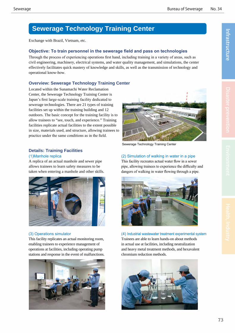
Overview: Sewerage Technology Training CenterLocated within the Sunamachi Water Reclamation Center, the Sewerage Technology Training Center is Japan’s first large-scale training facility dedicated to sewerage technologies. There are 21 types of training facilities set up within the training building and 12 outdoors. The basic concept for the training facility is to allow trainees to “see, touch, and experience.” Training facilities replicate actual facilities to the extent possible in size, materials used, and structure, allowing trainees to practice under the same conditions as in the field.
Details: Training Facilities
73
InfrastructureD
isaster preventionEnvironm
entH
ealth, IndustrySewerage Bureau of Sewerage No. 34
(1)Manhole replicaA replica of an actual manhole and sewer pipe allows trainees to learn safety measures to be taken when entering a manhole and other skills.
(2) Simulation of walking in water in a pipeThis facility recreates actual water flow in a sewer pipe, allowing trainees to experience the difficulty and dangers of walking in water flowing through a pipe.
Sewerage Technology Training Center
(3) Operations simulatorThis facility replicates an actual monitoring room, enabling trainees to experience management of operations at facilities, including operating pump stations and response in the event of malfunctions.
(4) Industrial wastewater treatment experimental systemTrainees are able to learn hands-on about methods in actual use at facilities, including neutralization and heavy metal treatment methods, and hexavalent chromium reduction methods.