Construction of a Clean Room Involving Plumbing ... room Tender specs.pdf · Annexure ‘E’ –...
48
1 National Centre for Nanoscience & Nanotechnology, University of Mumbai, (NCNNUM) National Center for Nanoscience and Nanotechnology, Ramkrishna Bajaj Sanskrut Bhavan, II floor, University of Mumbai, Vidyanagari, Santacruz (E), Mumbai 400 098, India. Tel: (022) 2654 3495, Fax (022) 26530299 Email: [email protected] Tender Document for Construction of a Clean Room Involving Plumbing, Electrical, and Allied Works at the Ground Floor of Nanocenter No: NCNNUM/Tender/299/2012 Date: 23 rd February 2012 Part A - Terms and Conditions Part B – Specifications Price: Rs. 500/- (non refundable) Important Dates: Period of sale of Tender Documents 23 rd February 2012 to 09 th March 2012 Pre-Bid Meeting 03 rd March, 2012, 9.00 am Last date of Sale of Tender Document 09 th March, 2012, 1.00 pm Last Date of Receiving sealed Bids/Tenders: 09 th March, 2012, 4.00 pm Tender opening (if minimum three bids is received) 13 th March, 2012, 3.00 pm
-
Upload
nguyenthuan -
Category
Documents
-
view
219 -
download
1
Transcript of Construction of a Clean Room Involving Plumbing ... room Tender specs.pdf · Annexure ‘E’ –...
1
National Centre for Nanoscience & Nanotechnology, University of Mumbai,
(NCNNUM)
National Center for Nanoscience and Nanotechnology, Ramkrishna Bajaj Sanskrut Bhavan, II floor,
University of Mumbai, Vidyanagari, Santacruz (E), Mumbai 400 098, India. Tel: (022) 2654 3495, Fax (022) 26530299 Email: [email protected]
Tender Document for
Construction of a Clean Room Involving Plumbing, Electrical, and Allied Works at the Ground Floor of Nanocenter
No: NCNNUM/Tender/299/2012
Date: 23rd February 2012
Part A - Terms and Conditions
Part B – Specifications
Price: Rs. 500/- (non refundable)
Important Dates:
Period of sale of Tender Documents 23rd February 2012 to 09th March 2012 Pre-Bid Meeting 03rd March, 2012, 9.00 am
Last date of Sale of Tender Document 09th March, 2012, 1.00 pm Last Date of Receiving sealed Bids/Tenders: 09th March, 2012, 4.00 pm
Tender opening (if minimum three bids is received) 13th March, 2012, 3.00 pm
2
Table of Contents Part A - Terms and Conditions........................................................................................................3
Tender Notice ...............................................................................................................................4
Terms and Conditions of Supply ..................................................................................................5
Criteria for Eligibility ...................................................................................................................9
Scope of Work & Submittals ........................................................................................................9
Schedule to Tender .....................................................................................................................10
Part B – Specifications ..................................................................................................................11
1. Design Philosophy & Technical Details .................................................................................12
2. Heating Ventilation & Air Conditioning Work ......................................................................23
3. Clean Room & Civil Finishes .................................................................................................29
4. Clean Room Accessories ........................................................................................................33
5. List of Approved Makes .........................................................................................................38
6. Installation and Training .........................................................................................................39
7. Acceptance and Completion ...................................................................................................39
Annexure ‘A’ – Layout of clean room........................................................................................41
Annexure ‘B’ – Layout of Satellite clean room (ISO – 8) facility as optional ...........................42
Annexure ‘C’ – Cleanroom Summary ........................................................................................43
Annexure ‘D’ – Specification for Optional Satellite Clean room...............................................45
Annexure ‘E’ – Format for submitting BOQ..............................................................................46
Annexure ‘F’ – Format for submitting compliance/response of bidder .....................................47

3
National Centre for Nanoscience & Nanotechnology, University of Mumbai,
(NCNNUM)
National Center for Nanoscience and Nanotechnology, Ramkrishna Bajaj Sanskrut Bhavan, II floor,
University of Mumbai, Vidyanagari, Santacruz (E), Mumbai 400 098, India. Tel: (022) 2654 3495, Fax (022) 26530299 Email: [email protected]
Tender Document for
Construction of a Clean Room Involving Plumbing, Electrical, and Allied Works at the Ground Floor of National Center for Nanoscience and Nanotechnology, University of
Mumbai. A Clean Room Consisting of Segments of Class- 10,000 (ISO-7), Class- 1000 (ISO-6) and Class- 100 (ISO-5) for Processing and Characterization Laboratory. (Detailed
Specification and Lay Out Drawing attached) One Complete Floor of Approximately 6700 square feet, with an optional adjoining satellite facility of ~ 700 sq ft Class 100,000 (ISO-8)
No: NCNNUM/Tender/299/2012
Date: 23rd February 2012
Part A - Terms and Conditions
4
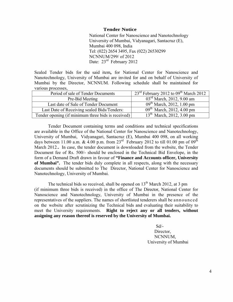
Tender Notice National Center for Nanoscience and Nanotechnology University of Mumbai, Vidyanagari, Santacruz (E), Mumbai 400 098, India Tel: (022) 2654 3495, Fax (022) 26530299 NCNNUM/299/ of 2012 Date: 23rd February 2012
Sealed Tender bids for the said item, for National Center for Nanoscience and Nanotechnology, University of Mumbai are invited for and on behalf of University of Mumbai by the Director, NCNNUM. Following schedule shall be maintained for various processes,
Period of sale of Tender Documents 23rd February 2012 to 09th March 2012 Pre-Bid Meeting 03rd March, 2012, 9.00 am
Last date of Sale of Tender Document 09th March, 2012, 1.00 pm Last Date of Receiving sealed Bids/Tenders: 09th March, 2012, 4.00 pm
Tender opening (if minimum three bids is received) 13th March, 2012, 3.00 pm
Tender Document containing terms and conditions and technical specifications are available in the Office of the National Center for Nanoscience and Nanotechnology, University of Mumbai, Vidyanagari, Santacruz (E), Mumbai 400 098, on all working days between 11.00 a.m. & 4.00 p.m. from 23rd February 2012 to till 01.00 pm of 09th March 2012.. In case, the tender document is downloaded from the website, the Tender Document fee of Rs. 500/- should be enclosed in the Technical Bid Envelope, in the form of a Demand Draft drawn in favour of “Finance and Accounts officer, University of Mumbai”. The tender bids duly complete in all respects, along with the necessary documents should be submitted to The Director, National Center for Nanoscience and Nanotechnology, University of Mumbai.
The technical bids so received, shall be opened on 13th March 2012, at 3 pm
(if minimum three bids is received) in the office of The Director, National Center for Nanoscience and Nanotechnology, University of Mumbai in the presence of the representatives of the suppliers. The names of shortlisted tenderers shall be announced on the website after scrutinizing the Technical bids and evaluating their suitability to meet the University requirements. Right to reject any or all tenders, without assigning any reason thereof is reserved by the University of Mumbai.
Sd/-
Director, NCNNUM, University of Mumbai

5
Terms and Conditions of Supply
1. The last date and time for the acceptance of the bids is 09th March 2012, 4.00 pm 2. Suppliers shall submit the following documents along with their quotations (which
should be placed in the Technical Bid Envelope). (a) Income-Tax clearance certificate f r o m t h e Income-Tax Officer concerned,
certifying that the tenderer has cleared all the Income-Tax dues. Copies of Income Tax returns shall be applicable.
(b) Suppliers should be either manufacturer or authorized dealer of the said equipment and should submit the proof for the same. Also, the suppliers should state whether they are a Proprietary Firm, Partnership Firm or a Private/Public Limited Company and furnish the proof of the same.
(c) The names of the organizations and laboratories for which similar work carried out. (d) Earnest Money Deposit in the form of a Demand Draft drawn in favour of
“Finance and Accounts officer, University of Mumbai” on any Nationalized Bank, payable at Mumbai. Alternately, BG from a Nationalised Bank only may be acceptable. The amount of Earnest Money Deposit shall be Rs. 2,50,000/- (Rs Two Lacs fifty thousand only).
(e) In case, the tender document is downloaded from the website, the Tender Document fee of Rs. 500/- should be enclosed in the form of a Demand Draft drawn in favour of “Finance and Accounts officer, University of Mumbai”
(f) VAT Registration No. (g) Technical specifications offered by the Supplier. (h) Technical compliance table
3. The rates should be mentioned in the Schedule attached with the Tender Document.
Each page of the tender shall be signed in full and stamped with the seal by the supplier. The supplier must clearly state in what capacity he or she is signing the tender. (which should be placed in the Financial Bid Envelope)
4. The supplier shall submit the tender in two envelopes. The first envelope (Technical Bid)
shall contain all the documents referred to in para two above and sealed. The second envelope (Commercial Bid) shall contain the Schedule, in which the supplier shall register the rates of supply. The second envelope shall also, likewise, be sealed. Both the envelope then should be put together, and shall be sealed in an envelope, and shall prescribe time and date. The Technical Bid shall be opened first to ensure that supplier have submitted all the requisite documents. If the Technical Bids are not in order or are deficient in some respect, the commercial bids in respect of such tenders shall not be opened. The date and time of opening the Financial bids shall be announced immediately after opening all the Technical bids.
5. Tender bids not accompanied by the requisite amount of Earnest Money Deposit are liable
to be rejected 6. The Earnest Money Deposit paid by the supplier shall be forfeited, if the supplier fails to

6
pay the necessary security deposit in the event of his tender being accepted. 7. The amount of Security Deposit/Performance Guarantee shall be 5 % of the cost. In case of
successful tenderer the amount of Earnest Money Deposit shall be converted in Security Deposit / Performance Guarantee. Security Deposit / Performance Guarantee shall be refunded after the warranty period is over. The Security Deposit / Performance Guarantee can be paid in the form of a Bank Guarantee from a scheduled bank will be deducted from the payments being made to the supplier against every bill.
8. Supplier should read carefully all the instructions and terms and conditions, etc before
registering rates in prescribed schedule of the tender. Taxes and duties etc, should be shown separately.
9. The offers made by the suppliers shall be open for acceptance within 120 days after the
last date of submission of tender.
10. The Technical Documents shall be opened by The Director, National Center for Nanoscience and Nanotechnology, at 3.00 p.m. on 13th March 2012, for those bids for which minimum three Vendors have participated. The tenderers or their authorized representatives shall be allowed to be present at the time of opening of the tenders. Financial bids of only qualified tenderers shall be opened. The date and time of opening the financial bids shall be announced immediately after opening all the Technical bids.
11. In case of imported items/equipments, the rates should be quoted in the light of exemptions
enjoyed by educational institutions. University is exempted from the payment of Octroi and the necessary certificate/form can be issued by the University. The customs duty applicable to the University of Mumbai is maximum 5% of the invoice.
12. Technical specifications of the instruments / equipments / articles are given in
Annexure to these papers (Part B). 13. The delivery, installation of the works should be completed within 15 weeks from placing
of the order. No extension shall be granted to the contractors/suppliers for the period of delivery, under any circumstances. All drawings need to be approved by NCNNUM. No change is allowed without written permission.
14. In case of delayed installation and completion in the construction of cleanroom involving
plumbing, electrical, civil and allied works at NCNNUM, liquidated damages at the rate of 1 percent per week of delay with a maximum of 5 percent will be levied.
15. If the supplier fails to deliver the article as per the delivery schedule, the University of
Mumbai shall be free to procure the balance/undelivered supply, at the risk and cost of the supplier, from other such suppliers
16. The goods, articles, materials supplied by the supplier shall be accepted after
7
inspection by an officer authorized by the competent authority. No articles/materials which do not conform to the specifications laid down in the terms and conditions or damaged in transit accepted
17. Before tendering, the tenderer shall inspect the site to fully acquaint himself with the condition in regard to accessibility of site, working condition of site and locality including stacking of materials, installation of tools and plants, etc., required for the satisfactory execution of the work contract as well as the security arrangements for the materials, equipment and personnel. No separate claim whatsoever on these accounts shall be entertained by the University of Mumbai
18. Pre-Bid Meeting:
With a view to provide clarifications, if any, on the technical and commercial aspects to the prospective bidders, NCNNUM shall hold a ‘Pre-Bid meeting’ at its premises at Sanskrut Bhavan, University of Mumbai on 03 March 2012, In light of the above said objective of the Pre-bid meeting, prospective contractors must ensure that they or their authorized representatives attend the same as per the above given schedule.
19. The bills of suppliers shall be paid by the University only after the complete installation of clean room as per the stated specification in the tender documents and certified test reports are submitted Completion: The order is considered to be complete when all of the following are satisfied a) The supplier has completed all construction and assembly to specification as mentioned
in Part B b) All HVAC, electrical systems, intercom and LAN points to be tested and activated c) The fire protection/alarm system, Building Management System (BMS) and biometric /
proximity access control systems has been tested and activated d) Acceptance tests as mentioned in Part B to be completed and test certificates are
satisfactory 20. Only those contractors who can execute the complete project shall submit their bids. Bids
received for part work shall not be considered. 21. Supplier has to arrange for materials unloading and staging. Any damage to the equipments
or building structure of National Centre for Nanoscience & Nanotechnology, University of Mumbai, shall be borne by the supplier.
22. Vendor must submit Compliance statement in tabular form comparing each specification of
the quoted item with that given in the Tender Document part B. The Vendor also must supply a soft copy of the Table only in Microsoft word format.
23. If the equipment is imported and requires PC, printer other peripherals, they can be bought
from India and should be of International brand such as HP. The monitor should be LCD/TFT screen. The printer should be LaserJet printer. The processor should be Intel latest processor. The amount quoted for the items bought in India, installation; servicing etc. can be
8
in Indian Rupees and the imported items can be quoted in foreign currency. 24. The warranty period shall be of 1 year from the date of complete and satisfactory
installation of the system. 25. As the suppliers shall be responsible for the supply and installation of equipment at
Mumbai, the cost towards insurance until destination in the University, shall be borne by suppliers.
26. In the event of any breach of the terms and conditions of the supply, the University of
Mumbai may terminate the contract placed with the supplier and forfeit the security deposit or the supplier.
9
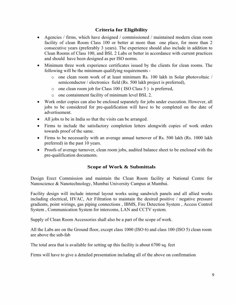
Criteria for Eligibility
Agencies / firms, which have designed / commissioned / maintained modern clean room facility of clean Room Class 100 or better at more than one place, for more than 2 consecutive years (preferably 3 years). The experience should also include in addition to Clean Rooms of Class 100, and BSL 2 Labs or better in accordance with current practices and should have been designed as per ISO norms.
Minimum three work experience certificates issued by the clients for clean rooms. The following will be the minimum qualifying requirements -
o one clean room work of at least minimum Rs. 100 lakh in Solar photovoltaic / semiconductor / electronics field (Rs. 500 lakh project is preferred),
o one clean room job for Class 100 ( ISO Class 5 ) is preferred, o one containment facility of minimum level BSL 2.
Work order copies can also be enclosed separately for jobs under execution. However, all jobs to be considered for pre-qualification will have to be completed on the date of advertisement.
All jobs to be in India so that the visits can be arranged.
Firms to include the satisfactory completion letters alongwith copies of work orders towards proof of the same.
Firms to be necessarily with an average annual turnover of Rs. 500 lakh (Rs. 1000 lakh preferred) in the past 10 years.
Proofs of average turnover, clean room jobs, audited balance sheet to be enclosed with the pre-qualification documents.
Scope of Work & Submittals Design Erect Commission and maintain the Clean Room facility at National Centre for Nanoscience & Nanotechnology, Mumbai University Campus at Mumbai.
Facility design will include internal layout works using sandwich panels and all allied works including electrical, HVAC, Air Filtration to maintain the desired positive / negative pressure gradients, point wirings, gas piping connections , IBMS, Fire Detection System , Access Control System , Communication System for intercoms, LAN and CCTV system.
Supply of Clean Room Accessories shall also be a part of the scope of work.
All the Labs are on the Ground floor, except class 1000 (ISO 6) and class 100 (ISO 5) clean room are above the sub-fab
The total area that is available for setting up this facility is about 6700 sq. feet
Firms will have to give a detailed presentation including all of the above on confirmation
10
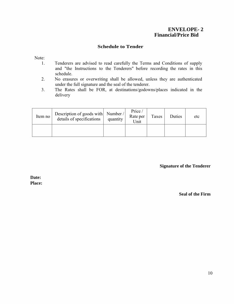
ENVELOPE- 2 Financial/Price Bid
Schedule to Tender
Note:
1. Tenderers are advised to read carefully the Terms and Conditions of supply and "the Instructions to the Tenderers" before recording the rates in this schedule.
2. No erasures or overwriting shall be allowed, unless they are authenticated under the full signature and the seal of the tenderer.
3. The Rates shall be FOR, at destinations/godowns/places indicated in the delivery
Item no Description of goods withdetails of specifications
Number /quantity
Price / Rate per
Unit Taxes Duties etc
Signature of the Tenderer
Date: Place:
Seal of the Firm
11
National Centre for Nanoscience & Nanotechnology, University of Mumbai,
(NCNNUM)
National Center for Nanoscience and Nanotechnology, Ramkrishna Bajaj Sanskrut Bhavan, II floor,
University of Mumbai, Vidyanagari, Santacruz (E), Mumbai 400 098, India. Tel: (022) 2654 3495, Fax (022) 26530299 Email: [email protected]
Tender Document for
Construction of a Clean Room Involving Plumbing, Electrical, and Allied Works at the Ground Floor of National Center for Nanoscience and Nanotechnology, University of
Mumbai. A Clean Room Consisting of Segments of Class- 10,000 (ISO-7), Class- 1000 (ISO-6) and Class- 100 (ISO-5) for Processing and Characterization Laboratory. (Detailed
Specification and Lay Out Drawing attached) One Complete Floor of Approximately 6700 square feet, with a optional adjoining satellite facility of ~ 700 sq ft Class 100,000 (ISO-8).
No: NCNNUM/Tender/299/2012
Date: 23rd February 2012
Part B – Specifications
12
Specifications for “Construction of a Clean Room Involving Plumbing, Electrical, and Allied Works at the
Ground Floor of National Center for Nanoscience and Nanotechnology, University of Mumbai. A Clean Room Consisting of Segments of Class- 10,000 (ISO-7), Class- 1000 (ISO-
6) and Class- 100 (ISO-5) for Processing and Characterization Laboratory. (Detailed Specification and Lay Out Drawing attached) One Complete Floor of Approximately 6700 square feet”. A satellite facility adjoining the proposed area with ISO class 8 facility for
~700 sq ft may be considered/quoted as optional
1. Design Philosophy & Technical Details National Centre for Nanoscience & Nanotechnology, University of Mumbai intends to build a Clean Room facility for it’s activities on Nanoscience over a floor area of about 6700 sq. feet.
Mumbai University intends to award the work of setting up theses labs on a turnkey basis. By the mention of the work being awarded on a turnkey basis, it is to be understood that the following works are included to be in the scope of work in the contract.
Building the lab with the right type of panels for the walls as well as the ceiling.
Electrification of the labs for the HVAC system, lighting and the lab equipments.
An efficient HVAC system which can meet the rigorous demands of air pressure, air velocity, humidity and temperature regime for the labs of this type.
An efficient building management system which manages and controls the various parameters of temperatures, pressures in the labs as well as indicate status of equipment in the labs.
Flooring to be 2 mm self leveling epoxy flooring with epoxy screed coving for the wall to floor finishes.
Supply of Lab furniture like the lab work benches, garment cubicle, fume hood, wet benches, pass boxes, locker cabinet.
Minor civil works for the installation of the HVAC system.
Instrumentation in the form of magnehelic gauges in the labs for indication of room pressures.
A reliable fire detection system to send out an alert in the unlikely event of a fire within the lab area.
Door Interlocks and access controls, communication system.
13
Validation of the facility for the parameters of design carried out in the presence of National Centre for Nanoscience & Nanotechnology approved validators.
In the following pages the requirements of the National Centre for Nanoscience & Nanotechnology with respect to the space, layout, inside temperature conditions, pressure regime for containment and others are enumerated in detail from which a detailed design can be attempted by the prospective contractors.
1.1 Facility layout
A single line layout of the area of proposed labs is enclosed. However the contractor can visit the site and confirm with dimensions etc.
There will be Class 10,000 (ISO 7) standard Yellow Room for organic electronics / Organic Chemistry Labs on one side and the other set of Labs will include the SEM Lab / AFM – Bio AFM / SPM Lab / TEM Lab/ FIB Lab/ Surface Analytical Lab / MBE lab and PED-PLD lab. Class 1000 (ISO 6) and Class 100 (ISO 5) clean room shall have a sub-fab, which forms a part of MBE and PED-PLD lab. There will be a small separate BSL 2 Lab isolated from this set of Labs. For more details, kindly refer Annexure ‘A’. A satellite facility adjoining the proposed area with ISO class 8 (class 100,000) facility for ~700 sq ft may be considered/quoted as optional
The labs shall have progressive positive pressure in the Labs. A clean room classification as per the enclosed layout is followed with clean rooms from ISO class 5 to ISO Class 7. (all at rest conditions )
The entry to labs could be through a common room/ Air Lock. Similarly, for the BSL Lab there will be a separate set of Air Lock / Change Room.
The Labs shall have one entry change room through which the researcher is able to follow a strict dress change and gowning routine. The station for the building management system can be housed in the Control Room near the PED-PLD Lab and Service Area. Dynamic Static Pass boxes to be located near to the air shower will aid in delivering materials in and out for work in the labs.
1.2 The construction of the facility
The whole lab facility shall be constructed with wall panels and ceiling panels, the type that are generally used for clean room application but built stronger to withstand rigors of a containment facility. There shall be an operating negative pressure in the BSL 2 facility and this negative pressure progressively reduces for each change room.
For facilitating good visibility, use of view panels constructed with double glazing shall be used. All doors should have large view panels without exception. The emergency doors in the corridor
14
opening to the Atrium shall be constructed for leak proof service with drop seal and side seals. The wall and ceiling panels for lab construction shall of the type convenient for penetration for the service lines and utilities and at the same time such penetrations, it should be possible for leak proof sealing.
All joints to be hot welded. Coving profiles to be used where the wall panel meets the floor. The lab flooring shall be epoxy 2 mm thick self leveling type to provide a seamless finish with epoxy coving where the wall panel meets the floor.
All the lab equipment requires power outlets on the wall panels as source of power. Most of them are single phase power sockets or outlets.
Many Lab equipments require uninterrupted supply of piped gas at the equipment location. Polished stainless steel tubing has to be drawn from a convenient location for the gas cylinders outside the labs on ground floor to the lab equipment requiring this gas. Locating the cylinder outside the lab will eliminate service personnel entering the lab area. The same is excluded from the scope of these works.
1.3 The HVAC system
For the BSL 2 lab, the HVAC design is vital to give the researchers the re-assurance of a good containment. Similarly, for the other Lab areas a graded positive pressure will give the researchers the required re-assurance.
It is proposed to work on infectious agents in the BSL2 lab and so it is proposed to have the cleanliness levels to class 10,000 levels.
Temperature for clean rooms having cleanliness class ISO class 7 is required to be 24° ± 2
degrees Celsius and relative humidity NMT 60%. For cleanliness class ISO 5 (class 100) and ISO 6 (class 1000) clean rooms and sub-fab, the required temperature is 22 ± 2 degrees Celsius, relative humidity NMT 45%.The HVAC system shall be re-circulatory. Return air riser / return air chase shall be provided to re-circulate the room air back to supply air.
Terminal filters provided at the supply air grilles can give the filtration. However, for the BSL 2 Lab , the HEPA Filters will be in the AHU .
Care has to be taken to design the filter housings for integrity test of the filter be it particle counts or the DOP tests. Annual filter integrity tests are a must for lab operation as a matter of lab validation.
15
Magnehelic gauges of the right pressure ranges shall be introduced at each entry point of the Lab so that the researchers can view the room pressure prior to entry into the Labs. These gauges provide the researchers the reassurance whenever they enter into the labs that the right pressures are maintained.
The biosafety cabinets in the BSL-2 lab are of the class II A type which exhaust 30% of its air to a volume of about 200 cfm each and there are two such cabinets in lab which have their own HEPA filter on the exhaust side exhausting independently.
The air handling units are to be mounted outside along with the chillers and the chiller pumps. The average air flow velocity for different class of room should follow minimum air flow velocity as below.
a) Class 10,000 (ISO 7) clean room : 20 ft/min
b) Class 1,000 (ISO 6) clean room : 45 ft/min
c) Class 100 (ISO 5) clean room : 90 ft/min
The recovery time from rest shall be less than 30 minutes for all the clean rooms. Less than 65 dB noise level with all the FFU’s ‘ON’, measured approximately 1 meter beneath the FFU at several location inside the clean rooms during normal operation.
Double skinned air handling units is the requirement of this application for the labs. All the fan motor drives are to be variable frequency drives to gain control through the building management system.
The design and the installation of the HEPA filters in the filter housings should be such as to facilitate filter integrity tests of particle tests and DOP tests not only during the installation but also during the annual validation of the labs.
1.4 The building management system
The reliability of the positive / negative pressure regime required for the containment is achieved and maintained by the building management system ( BMS ). Thus the BMS system has a very important function to perform in a lab of this type. The BMS will be on the Bacnet platform and with a host of pressure and temperature sensors, the variable frequency drives for the fan motors, the desired inside lab conditions are achieved and maintained. The software program for the building management system is written with the right logic take care of the following functions. The major parameters to be controlled & monitored are a) Temperature, b) Humidity, c) Differential Pressure and d) Air flow. The supplier shall provide a hand held Airborne Particle
counter for 0.3/0.5/5 m particles.
16
Maintain the set positive / negative pressures in the lab and the change rooms and take corrective action through the variable frequency drives whenever changes to positive / negative pressures against set values occur.
Create history sheet of the actual positive / negative pressures in the labs and the change rooms recorded every thirty minutes. Minimum six months data on the system should be available for scrutiny at any given point of time.
Any variations in the positive / negative pressures recorded for over a two minute period of time should show in the form of an alert of an audio signal as well as a pop up on the screen of the monitor.
Static pressures on the upstream side of the HEPA filters with possibility of indication of a clog in the filters for filter replacements is needed.
An alert in the drop of positive/ negative pressure in the lab to have an audio alert in the Lab & at the BMS Control Room.
The BMS system has to have additional capacity of DDCs to monitor the status of some of the vital BSL 2 lab equipments like the -80 degree freezer and the -20 degree freezers , remote sensing for the biosafety cabinets, autoclaves.,
The BMS System will also monitor the status of fire detection system, access control system. The supplier shall supply schematics and engineering drawings for the control systems. The supplier shall incorporate particulate monitoring and fan filter unit controls at a central location.
The sensors for the pressure and the temperature used for the BMS should all be supplied with their factory calibrated certificates.
The BMS software is to be loaded into a PC of suitable specs with a flat monitor and laser printer, the whole system to be set in the Control Room
1.5 Lab Electrification
Except for the some equipments which require three phase power supply of about 5 kW, all the power sockets in the labs and the change rooms and the air lock room are to be single phase 6/16 A 230 Volts modular type with individual switch control ( universal type ) of a reputed make . There shall be two types of power distributions. Uninterruptible power supplied through power sockets of a different colour for easy identification. The number and location of these power sockets shall be made known in due course. Raw power again identified by power sockets of a particular colour. Both the power sources to be backed up on available DG Power and UPS System. The total power requirements for the facility to be indicated separately for captive power
17
and uninterrupted power. The power will be sourced from University of Mumbai and be made available at one point. The distribution has to be planned by the bidder.
For convenience and flexibility in locating the lab equipment in positions of researcher's choice it is ideal to have all the power sockets located at a height of 1000 mm above the floor level. The power sockets if placed at 1000 mm width intervals on the wall panels it shall be most convenient to manage equipment movement within the lab.
The lighting level at the work bench height in all the labs as well as the change rooms shall be over 500 lux measured with a lux meter at 1 meter above the clean room floor. Compact fluorescent light fittings are the ideal choice. Access for any service for the light fittings are from over the top of the ceiling panels of the lab (except for some areas wherein top access is difficult) One lighting fixture in each room shall be brought on the UPS power for handling situations during power interruptions.
All electrical sockets / equipments / circuits shall be protected with MCBs and MCCBs.
1.6 Fire detection system
The whole clean room area shall be covered by a fire detection system with photo-electric type of fire detectors placed distributed to cover all areas of the labs and the wash room. An addressable fire panel shall be located near the BMS station. It shall also have an audible alert signal hooter of a good decibel value to attract attention of the staff for action.
An auto-dialing facility shall be available in conjunction with the BMS for remote alert to selected personnel identified for the purpose. The unlikely event of the fire alert shall also trigger the release of the access control system on the doors as well as initiate the fire dampers in the supply air ducts to close.
The penetrations in the ceiling panels for the cabling of the fire detectors need to be leak sealed.
Fire suppression shall be managed with the aid of portable fire extinguishers of the right type placed strategically outside the labs.
1.7 Door interlocks and access control for entry to labs
The main entry door near the change room should have access control system with the bio-metric / proximity type of reader and magnetic locks. The doors to the change rooms shall have magnetic locks and inter locks so that no two adjacent doors can open at the same time. An inter lock defeat option shall be added to the system.
Each air-shower should be able to open only after successfully verification / validation of proximity type card reader access system validates the authorization for the person / proximity card.
18
The access control system shall be controlled through software and it should be possible for data of personnel movement in and out of the labs to be stored in a PC as a record. Storage of at least a month's data is the minimum requirement.
1.8 Clean Room Accessories
Air Showers, Pass Box, Fume hood, Wet benches & Garment Storage Locker cubicles in the Air Lock and such shall form part of Clean Room Accessories.
1.9 Voice and LAN data communication
A strict gowning procedure for the researchers shall be put in place during their work in the labs which makes the frequent movement in and out of the labs cumbersome. So a good voice and LAN data network shall be provided for the communication purposes. Tenderer should provide the wall hung telephone instruments compatible with the systems existing in Mumbai University for each room/lab and LAN data points at each room to access local area network of Mumbai University.
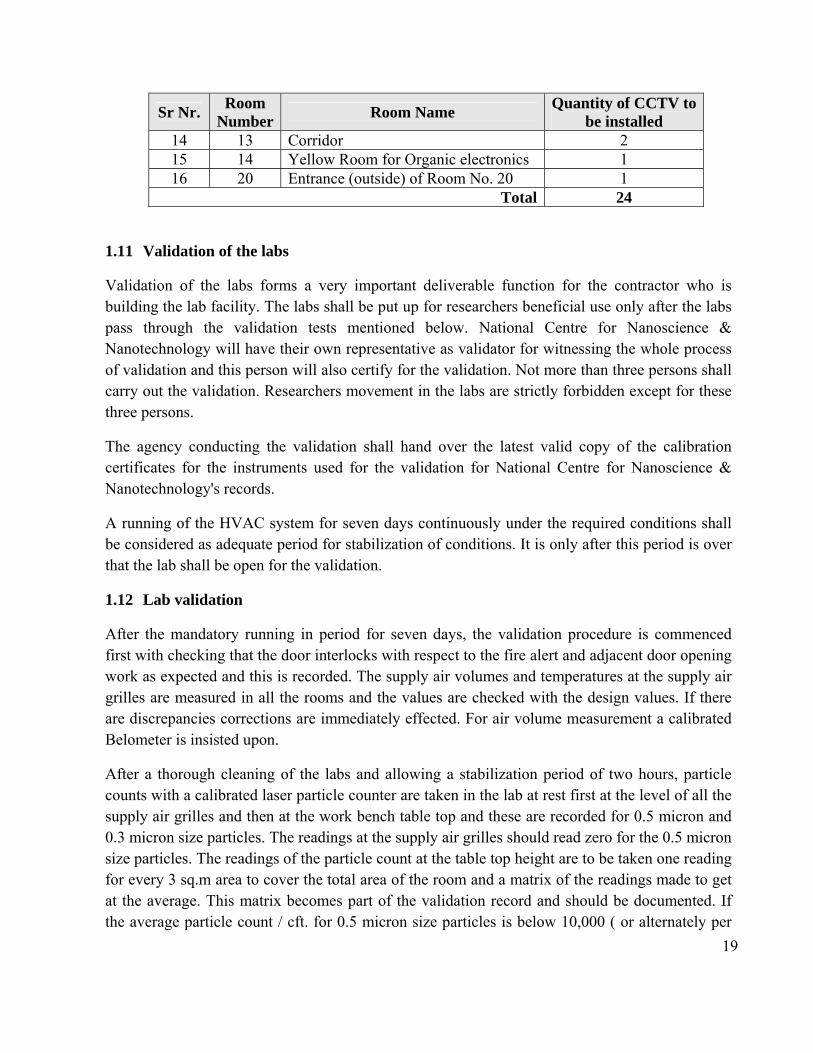
1.10 CCTV Camera
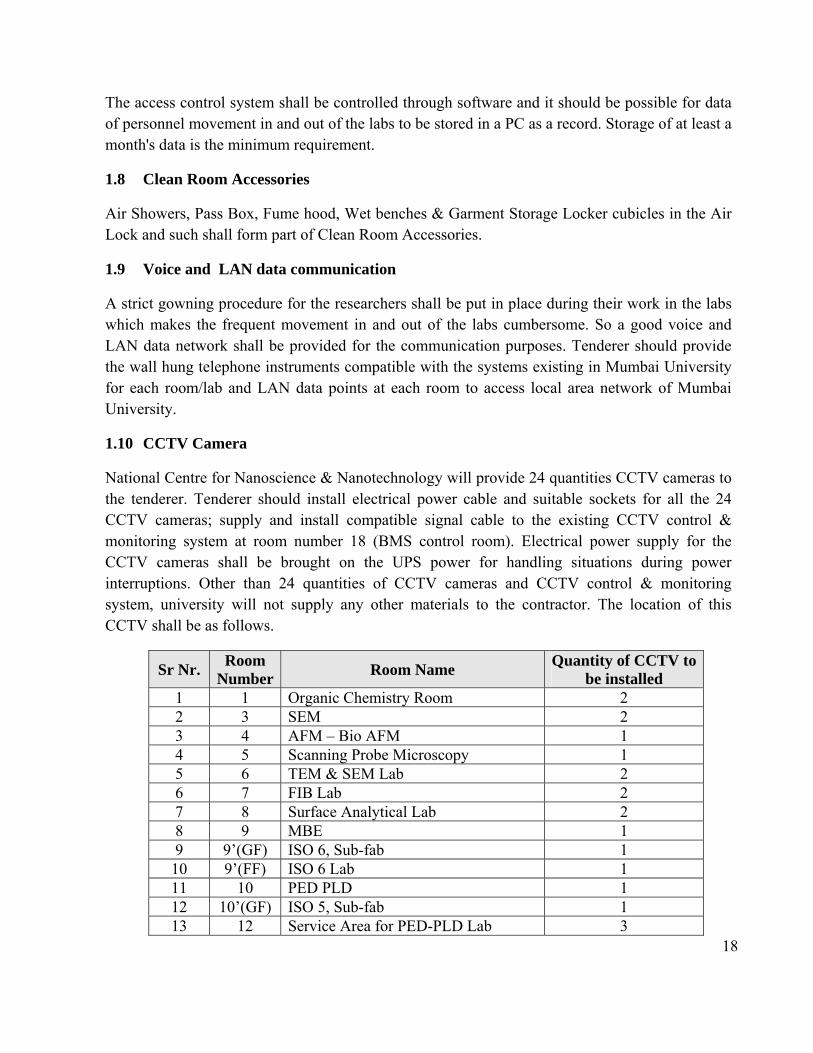
National Centre for Nanoscience & Nanotechnology will provide 24 quantities CCTV cameras to the tenderer. Tenderer should install electrical power cable and suitable sockets for all the 24 CCTV cameras; supply and install compatible signal cable to the existing CCTV control & monitoring system at room number 18 (BMS control room). Electrical power supply for the CCTV cameras shall be brought on the UPS power for handling situations during power interruptions. Other than 24 quantities of CCTV cameras and CCTV control & monitoring system, university will not supply any other materials to the contractor. The location of this CCTV shall be as follows.
Sr Nr. Room
Number Room Name
Quantity of CCTV to be installed
1 1 Organic Chemistry Room 2 2 3 SEM 2 3 4 AFM – Bio AFM 1 4 5 Scanning Probe Microscopy 1 5 6 TEM & SEM Lab 2 6 7 FIB Lab 2 7 8 Surface Analytical Lab 2 8 9 MBE 1 9 9’(GF) ISO 6, Sub-fab 1 10 9’(FF) ISO 6 Lab 1 11 10 PED PLD 1 12 10’(GF) ISO 5, Sub-fab 1 13 12 Service Area for PED-PLD Lab 3
19
Sr Nr. Room
Number Room Name
Quantity of CCTV to be installed
14 13 Corridor 2 15 14 Yellow Room for Organic electronics 1 16 20 Entrance (outside) of Room No. 20 1
Total 24
1.11 Validation of the labs
Validation of the labs forms a very important deliverable function for the contractor who is building the lab facility. The labs shall be put up for researchers beneficial use only after the labs pass through the validation tests mentioned below. National Centre for Nanoscience & Nanotechnology will have their own representative as validator for witnessing the whole process of validation and this person will also certify for the validation. Not more than three persons shall carry out the validation. Researchers movement in the labs are strictly forbidden except for these three persons.
The agency conducting the validation shall hand over the latest valid copy of the calibration certificates for the instruments used for the validation for National Centre for Nanoscience & Nanotechnology's records.
A running of the HVAC system for seven days continuously under the required conditions shall be considered as adequate period for stabilization of conditions. It is only after this period is over that the lab shall be open for the validation.
1.12 Lab validation
After the mandatory running in period for seven days, the validation procedure is commenced first with checking that the door interlocks with respect to the fire alert and adjacent door opening work as expected and this is recorded. The supply air volumes and temperatures at the supply air grilles are measured in all the rooms and the values are checked with the design values. If there are discrepancies corrections are immediately effected. For air volume measurement a calibrated Belometer is insisted upon.
After a thorough cleaning of the labs and allowing a stabilization period of two hours, particle counts with a calibrated laser particle counter are taken in the lab at rest first at the level of all the supply air grilles and then at the work bench table top and these are recorded for 0.5 micron and 0.3 micron size particles. The readings at the supply air grilles should read zero for the 0.5 micron size particles. The readings of the particle count at the table top height are to be taken one reading for every 3 sq.m area to cover the total area of the room and a matrix of the readings made to get at the average. This matrix becomes part of the validation record and should be documented. If the average particle count / cft. for 0.5 micron size particles is below 10,000 ( or alternately per

20
cu.m. as per ISO 14644 standards for Clean Rooms ); the particle count validation passes. If the count is more then the system should be examined for corrections.
The HEPA filter plenums shall be tested for the integrity of the HEPA filters with a DOP test. Percentage leaks through the filters shall be checked for being within acceptable limits.
All the validation certificates of the pressure sensors and the temperature sensors in the HVAC system are to be submitted to National Centre for Nanoscience & Nanotechnology for their records.
The various pressures of the individual rooms indicated by the magnehelic gauges as well as the BMS system shall be cross checked with validated instruments brought for the purpose.
The light intensity in the labs shall be measured at 1 meter above the floor level with the lux meter and recorded. The interlock provided for the independent exhaust fan for the working of the biosafety cabinet shall be checked for proper working.
The BMS system is tested for its stable operation. Response tests on BMS shall be carried out by changing parameters of pressure, air velocity, humidity and temperature and noting down the response time for conditions to stabilize.
Alerts in the form of pop ups on the screen for variations of pressures, humidity and temperatures other than the set values shall be checked.
The Lab facility shall be handed over to the researchers after all the points for checking the validation enumerated above pass for this lab after a fumigation process ensuring that all the lab equipment are in their place installed and commissioned.
1.13 Requirement of facilities to be considered in the layout
A separate entry with Air Shower for the corridor adjacent to SEM lab A separate entry with Air Shower for yellow room for organic electronics (room number
14) A separate entry with Air shower for Class 1000 (ISO 6). Each air-shower should be able to open only after successfully verification / validation of
proximity card access system validates the authorization for the person/card. Class 1000 (ISO 6) and Class 100 (ISO 5) should have sub-fab having height of about 8
feet. Tenderer should provide and install fume hoods / wet benches for room 1, 9, 10, 10-
Subfab, 10FF (wet benches) and 17. Service Areas air-conditioned using split AC to house the services for the labs. This has a
separate access from the outside. BSL 2 Lab along with it’s own Change Room and Air Lock to be housed separately. This
area is isolated physically as well from the other Labs.
21
Provision for the equipment movement during the initial stages using double leaf doors which will remain closed thereafter and provide perfect seal / isolation from outside to prevent any contamination.
The areas to have adequate no. of view panels to see the activities from outside without intruding into the space.
A satellite facility adjoining the proposed area with ISO class 8 (class 100,000) facility for ~700 sq ft may be considered/quoted as optional
1.14 Brief summary of scope of tender / job
Supply of air-cooled chiller units with microprocessor controls and Air handling units. Interconnecting piping, all ducting, Terminal HEPA filters, clean room finishes- comprising of metallic sandwich wall panels, aluminum honey comb panels, ceiling panels, covings, epoxy flooring, perforated floor panel and wall and ceiling finishes for non clean zones. Accessories such as garment cubicles, fume hoods, wet benches, laminar air flow workstation, cross over bench. Fire detection / alarm system, LAN systems, intercom for each lab, BMS Controls, control panel and automation for un- attended running of the total system. Electrical Panels for all equipments & lightings etc.
1.15 Supplies
Double skin Air-handling units are required for the laboratories/Clean rooms and for other non clean room areas.
Air handling units for all the areas will be complete with supply air fans. Floor mounted double skin air handling units for Labs. Such air handling unit(s) will have
a casing thickness of 25 mm with 24 G G.I pre coated outer sheet & 24 G G.I plain inner sheet. All air handling units are proposed with stainless steel drain tray. Fine filter plenums also form a part of the unit. The detailed specs are as per enclosure. Air handling units are modular and compact in construction and have low noise level. The air handling unit is proposed based on the zoning, cleanliness levels, inside conditions and duration of operation. Supply air will be taken to the various areas by means of GSS ducting duly insulated and distributed by diffusers/HEPA terminal boxes. Exhaust/return air is collected by means of concealed return air raisers, return air diffusers/grills, local exhaust of fume hoods shall be as per specs given separately. All ducts supply/return shall be insulated for conditioned areas.
Supply and return air ducts for the clean room & non clean room areas are of G.S.S
construction. Terminal HEPA filters are provided for the clean rooms.
The ducting will run above the false ceiling and distribution is by means of diffusers/grilles/terminal boxes.

22
Special mention is made about the flame spread / oxygen level index of various materials and equipments and only the materials and equipments strictly conforming to the same are to be used.
Electrical work for motor control centre, control panels for various HVAC equipments
such as AHUs, Condensing Units, inter connected cabling is included in the scope of the air-conditioning package. The main incomer from transformer to isolator switch in the plant room will be provided by the user.
Civil works such as construction of plant room, AHU room, cutouts, foundation for
mounting AHUs, roof shed over the AHU/condensing unit for protection from rain water will be organized through other agencies by user. The required marking, drawings are to be provided by the air-conditioning contractor well on time.
Air conditioning ducts are to be insulated with closed cell cross linked polyethylene foam.
1.16 Documentation
All documentation shall be in English language. Drawing shall be submitted in soft (AutoCAD format) and hard copy. In addition to the hard copies, soft copies to be submitted vide – CD. Documents to be submitted along with the ‘Technical Bid’ are as follows
a) Point wise confirmation of the specifications
b) Proposed design document and drawings including clean room walls, ceiling, lighting, Fan filter unit / HEPA filters, AHU, etc.,
c) Air Distribution ductwork showing ducting arrangement, size, supporting arrangement, etc.,
d) Electrical distribution network
e) Technical write up on installation / erection / commissioning procedures, quality check procedure etc.,
f) Material’s data sheet, QA and testing plan
g) Specifications of all standard components to be used
h) Schematics and engineering drawings for the control systems of building management system (BMS)
i) Delivery / job schedule with break up of milestones shall be provided along with the offer
j) The bidder shall provide Bill of Quantities (BOQ) in the format given in annexure – C
k) The bidder shall provide their compliance/response in the format given in annexure – D.
l) Any other technical detail needed for evaluation of the bid.
m) Deviations, if any, from these specifications needs to be clearly specified.
23
2. Heating Ventilation & Air Conditioning Work
2.1 FLOOR MOUNTED AIR HANDLING UNITS The AHUs will be in conformity to the latest manufacturing guidelines and in conformity to ASHRAE standards. 2.1.1 General Description of Air Handling Unit The scope of this article comprises of the design, manufacture, testing at manufacturers works, installation, testing and commissioning of Air Handling Units. Air Handling Units capable of the duty as specified in the schedule of equipment shall be provided by the bidder. 2.1.2 Codes & Standards The design, manufacture, inspection testing of AHU shall comply with all currently applicable statures, regulation, and safety codes in the locality where the AHUs are to be installed. The equipment shall also conform to the latest applicable Indian/International Standards i.e. ARI/CEN Certified. Nothing in this specification shall be constructed to relieve the Contractor of his responsibility. 2.1.3 Type: The Air Handling Units shall be in double skin construction with ≥40mm thick PUF insulation profile comprising of various section described below sequentially in the direction of airflow.
a. Mixing Section for return & fresh air with manually operated volume control damper having extended shaft suitable for motorized operation in case of future requirement.
b. Fresh air damper should be provided with HDPE insect mesh along with VCD. c. Pre Filter section. d. Multi row deep cooling coil section with insulated SS drain pan. e. Fan section with belt driven centrifugal DIDW Backward / Forward curved fans
complete with fan motor base frame, slide rail for motor, belt drive or direct drive arrangement.
f. Fine filter section g. Wing nut should be used for fixing of filters.
2.1.4 Housing /Casing construction: The unit casing construction shall have double skin to allow access without damaging the installation. The frame work shall be of extruded aluminium hollow sections of 2.5 mm thick. The frame shall be assembled using nylon type corner profile joints to make a study, strong and self supporting frame work for various sections. The whole unit shall comprise of galvanized sheet double skin casing with ≥40mm thick PUF insulation of density 38+/-2 kg / m3.
24
Double skin panels shall be 25mm thick fabricated out of best quality pre-coated 24 G GI on outer side and 24 G plane Galvanized sheet to inner side with PUF insulation injected in between. Polyurethane foam of density not less than 38+/-2 Kg/M3 shall be sandwich between inner and outer sheet. The panels shall be fixed on thermal break profile in such a manner that fixing screw head does not project on outer face on the panel and sharp end of the screw does not project inside the unit through double walled rib. Drain tray will be fabricated out of 18 G stainless Steel 304 Sheet with necessary slope to facilitate faster removal of condensate. The tray shall have sufficient depth and proper size drain connection. The tray will be insulated from outside with closed cell / PUF sheet having thickness not less than 10mm. Gasket sleeves at coil header outlet shall be provided to avoid any obstruction at time of coil removal. 2.1.5 Motor and drive Fan motors shall be 415 +/- 10% voltage, 50 cycles, 3 Phase squirrel cage, totally enclosed fan cooled with IP-55 protection. Motor shall be specially designed for quite operation. Drive to fan shall be provided through belt-drive arrangement. Belt shall be of the oil-resistant type. AHUs serving flame proof areas will have flame proof motors. 2.1.6 Fan The fan shall be backward/forward curved, double inlet double width type. The wheel and housing shall be fabricated from heavy gauge galvanized steel. The fan impeller shall be mounted on a solid shaft supporting to its scroll on angle iron flame and pillow block heavy duty ball bearings. The impeller and fan shaft shall be statically and dynamically balanced. The fan outlet velocity should be kept minimum. Fan housing with motor shall be mounted on a common steel base mounted inside the air handling unit housing on anti vibration springs, mounts or cushy foot mounts. Blower section will consists of extruded sections of proper size to facilitate the mounting of fan and motor bracket. Direct contact of fan base frame and AHU casing will be eliminated through vibration isolator. Also flexible connection will be provided at the fan outlet. Suitable panel of blower section will be provided with hole for cable entry with required arrangement to cover the sharp edge GI Sheet. If required a proper size box cover will be provided on cable entry location. A provision for earthing will be provided to main frame near the cable entry hole. 2.1.7 Cooling/ Heating Coils Supplier should provide suitable HVAC chiller unit, pumps for chilled water. CHW type coils shall have 12.5mm dia tubes minimum 24 G thick with aluminium fins firmly bonded to copper
25
tubes assembled in zinc coated steel frame. Face and surface areas should ensure rated capacity from each unit and be such that air velocity across each should not exceed 2.54 Meters/sec. The coil shall be pitched in the unit casing for proper drainage. Each unit shall be factory tested at 21 kg per sqm air pressure under water. Tube shall be hydraulically/mechanically expanded for minimum thermal contact resistance with Fins. Fin spacing shall be 11 to 13 fins per inch [4 to 5 fins per cm] 2.1.8 Filters
Each unit shall be provided with a Filter Section shall have rigid construction filter frame fabricated out of GI Sheet to house required size filters. 2.1.9 Accessories Inspection doors at required location will be provided with elegant design hinges made out nylon. Two or more number of hinges per door will be provided depending upon the size of the door to provide required rigidity to the door panel. One or more number of door handles will be provided with cam type tightening arrangement. The handle and cam will be made out of files nylon having galvanized iron spindle. The inspection door for blower section will be provided at such a location that the motor and drive package and fan bearing can be assessed for easy maintenance. The inspection doors of the sections accommodating filters will be of sufficient size to take care of filter removal. The entire AHU assembly will be mounted on a common skid fabricated out of 16 G / 18G GI Channel of 100 mm x 50 mm size. The skid will be secured with AHU Frame structure through threaded fasteners. All nut bolts, sheet metal screws, fasteners will be Zinc/Nickel plated having resistance against rusting. Each air handling unit shall be installed on neoprene rubber pads or isolation springs. 2.1.10 Safety Features: Each Air Handling Unit shall have safety features as under:-
a. The fan access door shall be equipped with micro switch interlocked with fan motor to enable switching off of the fan motor automatically in the event of door opening.
b. Fan and motor base shall be properly earthed from the factory. c. Light inside the AHU interlocked with door switch.
2.1.11 Performance Data: Air handling units shall be selected for the lowest operating noise level of the equipment. Fan performance rating and power consumption data with operating points clearly indicated shall be submitted and verified at the time of testing and commissioning of the installation.
26
2.1.12 Testing: Cooling/heating capacity of the various Air Handling Unit models shall be computed from the measurements of airflow and dry and wet bulb temperatures of air entering and leaving the coil. Flow measurements shall be by Anemometer and temperature measurements by accurately calibrated temperature measurement system. Computed results shall conform to these specified capacities and quoted ratings. Power consumption shall be computed from measurement of incoming voltage and input current. The AHU shall be tested in accordance with DW 142/AMCA 210. 2.2 SUPPLY AIR AND HEPA PLENUMS Air plenums shall be of GSS construction housing fabricated out of 1.2mm thick outer sheet duly powder coated. The plenum/box shall be provided with suitable air tight arrangement for mounting the FFU units / HEPA filter from the room side. The Volume control will be provided through the housing extending to the room side, for ease of air and pressure balancing. The plenum shall be hung from the ceiling using factory made supports. 2.3 DAMPERS Dampers shall be of opposed blade type for throttling and parallel acting blades for isolation. Multiple units working in tandem shall be provided with outlet dampers. Suitable links, levers and quadrants shall be provided for proper operation, control and setting of the dampers. Every damper shall have indicating device clearly showing the damper positions at all times. The casing the leaves of the dampers shall be of GSS duly powder coated. The dampers for exhaust shall be provided with limit switch for monitoring the open/close position through automation system, if opted for. The outlet Dampers at the AHU’s will be motorized for shutting off, on receipt of signal from the fire detection system. Fire dampers shall be provided in all the supply ducts, return ducts, return air passage in the air-handling unit room and at all floor crossing. 2.4 FILTERS
Provisions to monitor the filter clogging and functioning of filter units should be incorporated. HEPA filters and ULPA filters with FFU shall be installed according to the cleanliness classification of the rooms.
2.4.1 FINE FILTERS The fine filters shall have Non-woven felt of polypropylene medium in the form of a fabric. The separators shall be of tubular aluminium supports. The filter casing shall of CRCA sheet with expanded polyethylene gaskets. The collection efficiency shall be 90-92% down to 5 microns by

27
particle count down method. Fine filters shall be installed on / Aluminium powder coated frame work as mentioned in the drawings/schedules. Test certificates shall be provided for the filters. 2.4.2. HEPA FILTERS HEPA filters shall be of micro media type having a minimum efficiency of 99.97% particles of size down to 0.3 micron by DOP method. The filter shall be mounted on aluminum frame work. The tenderer shall furnish a test certificate. The supplier shall supply adequate number of Fan Filter Units (FFU) with HEPA filters incorporated into the ceiling design to provide the specified cleanliness rating and air flow velocity. FFU of 4’ x 2’ and 2’ x 2’ size shall be complete with blower, pre filter and HEPA filters suitable to mount on cleanroom ceiling grid system. Variable speed adjustment for the FFU should be provided.
2.5 ELECTRICAL CONTROL PANEL
The motor and switchgears required for various items shall generally be as as per specifications given below all electric motors shall be suitable for 3 Phase, 50 cycles, 415 volts A.C. supply +/- 10%.
Starters upto 7.5 kW shall be DOL type & above 7.5 kW shall be Star-Delta type. Cabling for electrical supply from floor mounted electrical panel to respective
AHUs/Condensing Units/Dehumidifier shall be aluminium armoured. Termination of cable at AHU/VU motors and at electrical panel shall be in scope of
HVAC contractor. However, termination of incoming cable at electrical panel shall be provided by other agency hired for electrical work.
Copper lugs should be used for cable termination. Bus bar for incoming should be of Copper.
2.6 DUCTING
Ducts shall be made with galvanized steel sheet. The galvanized steel sheet shall confirm to IS: 277-1965. G.I sheet used for ducting shall be of 120 GSM quality. Further note that 0.63mm G.I duct in comfort areas can be provided G.I flanges. Insulation on the ducting shall be closed cell fire retardant with Aluminum facing. The duct construction shall be as follows:

28
Rectangular Duct Construction Max. SIDE (mm) Thickness Type of Joint GSS Sheet Bracing Upto 750 22 G 25x25x3mm MS Angle None
Flange 751 to 1500 20 G 25x25x3mm MS Angle 25mmx3mm Flange upto 1000mm & MS Angle 40x40x3mm upto 1500mm 1501 to 2250 18 G 40x40x5mm MS angle 40mmx3mm
Flange MS angle
2251 & above 14 G 50x50x5mm MS 40mmx3mm MS Angle Flange MS angle
Hangers for Duct
Duct Size Spacing Size of Rod Dia (mm) (m) (mm) Upto 750 2.5 8 751 to 1500 2.5 10 1501 to 2250 2.5 12 Note: a) All ducts shall have angle iron flanges with suitable coating or treatment to prevent from
rusting or corrosion. b) Ducting for classified areas shall be provided food grade sealant to avoid air loss from
joints.
2.7 CAULKING Wherever duct passes through wall or slab, all the openings between Masonry and duct work shall be neatly caulked or sealed by the contractor to prevent movement of air from one space to the adjoining space. 2.8 INSULATION
Technical Specifications of Closed Cell, Chemically Cross-Linked Polyethlene (XLPE) Insulation or better.
The insulation material for ducts and pipe shall be closed cell cross-linked Polyethlene
foam. The thermal conductivity of the material shall not exceed .036 W/Mk at an average
temperature of 400 C.
29
The product shall have bending trial and dimensional stability as per DIN 51949 and DIN 53431 for an operating range of – 400c to + 1100c.
The density of the material shall be 30 +/- 3 Kg/M3 or .030gm/Cc. The material shall be rated as Class 0, as per BS 476 Part 7. The rating as per DIN 4102
shall be B1. The smoke density of the material as per AS-1530.3 shall not exceed 1. The water vapor permeability as per Din 52615 shall not exceed 0.15ng/M.Sec.Pa The material shall have a fire approval from CBRI/Fire Advisor (Govt of India)/Chief Fire
Officer. For providing UV protection on exposed ducting the insulation shall be cladded with
minimum 30 micron aluminum PE foil. The cladding shall be factory finished to avoid site work. The minimum thickness will be as per specs. The insulation material will be provided with self adhesive covered peel off paper, (as an alternative)
2.9 Application The duct/pipe surfaces will be thoroughly cleaned prior to applying the insulation to avoid application of adhesive in the field the insulation shall be provided with self adhesive, otherwise the adhesive of suitable grade shall be uniformly applied on the insulation and cured, before sticking to the duct. The insulation can be wrapped around the duct as one piece, where size does not permit the same be cut to exact width/height of duct. The duct /pipe insulation joints will be overlapped with a self adhesive tape of the same material. The tape shall be minimum 2.5mm thick and 50 mm wide. A self adhesive strip of same material, of suitable thickness (height), to cover the complete height of the flange will be provided around the flanges and the flange joint neatly covered with insulation, so as to reduce heat loss through flanges in addition to covering the flange connection/joint. For pipe insulation the material should be cut using a die /template to be provided by the manufacturer to ensure proper 450 angle is cut and the joining/overlapping of the insulation does not cause any bulging or stretching.
3. Clean Room & Civil Finishes
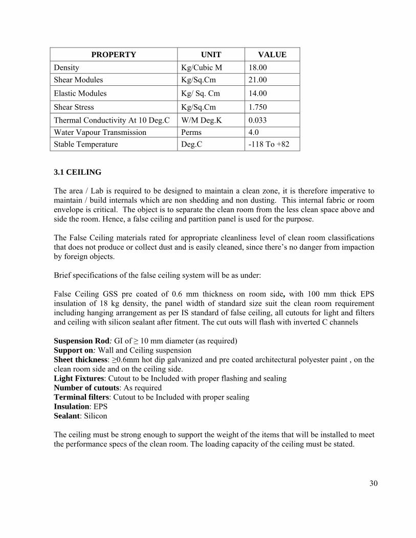
The internal finishes for the clean rooms are using Metallic Panels .The panels are to be self supportive and environmentally friendly (CFC free). The metal clad panels should have a natural vapour seal characteristic which when combined with the panel resistance to Thermal conductivity, creates the ability to withstand the most extreme temperature differentials. The properties for the wall and ceiling system shall be as below or better.
30
PROPERTY UNIT VALUE
Density Kg/Cubic M 18.00
Shear Modules Kg/Sq.Cm 21.00
Elastic Modules Kg/ Sq. Cm 14.00
Shear Stress Kg/Sq.Cm 1.750
Thermal Conductivity At 10 Deg.C W/M Deg.K 0.033
Water Vapour Transmission Perms 4.0
Stable Temperature Deg.C -118 To +82
3.1 CEILING The area / Lab is required to be designed to maintain a clean zone, it is therefore imperative to maintain / build internals which are non shedding and non dusting. This internal fabric or room envelope is critical. The object is to separate the clean room from the less clean space above and side the room. Hence, a false ceiling and partition panel is used for the purpose. The False Ceiling materials rated for appropriate cleanliness level of clean room classifications that does not produce or collect dust and is easily cleaned, since there’s no danger from impaction by foreign objects. Brief specifications of the false ceiling system will be as under: False Ceiling GSS pre coated of 0.6 mm thickness on room side, with 100 mm thick EPS insulation of 18 kg density, the panel width of standard size suit the clean room requirement including hanging arrangement as per IS standard of false ceiling, all cutouts for light and filters and ceiling with silicon sealant after fitment. The cut outs will flash with inverted C channels Suspension Rod: GI of ≥ 10 mm diameter (as required) Support on: Wall and Ceiling suspension Sheet thickness: ≥0.6mm hot dip galvanized and pre coated architectural polyester paint , on the clean room side and on the ceiling side. Light Fixtures: Cutout to be Included with proper flashing and sealing Number of cutouts: As required Terminal filters: Cutout to be Included with proper sealing Insulation: EPS Sealant: Silicon The ceiling must be strong enough to support the weight of the items that will be installed to meet the performance specs of the clean room. The loading capacity of the ceiling must be stated.
31
3.2 WALL PANELING SYSTEM
The Wall Paneling materials rated for appropriate cleanliness level of clean room classifications that does not produce or collect dust and is easily cleaned, since there’s no danger from impaction by foreign objects. Wall panels shall meet electrical resistance requirements of 106 – 109 as recommended by ANSI/ESD S20.20 to allow the dissipation of static charge as well as provide sufficient protection to personnel from electrical accident. Wall Paneling system should be, in line and sympathy to the ceiling system and shall be GSS pre coated of 0.6mm thickness on both side, with 100 mm thick EPS insulation of 16-18 kg density, the panel width will be 1.18 m with length to suit the clean room height. All joints shall be sealed with silicon sealant after fitment. The panels shall have in built return air raisers for extracting room air. The air quantity for the raiser to be estimated by the contractor keeping in mind the return air velocities of NMT 800 fpm. The paneling system with in-built Return Air Raisers shall provide flush finish on clean room side. All the existing beams, which are inside the cleanroom area, shall be concealed with suitable wall panel system rated for appropriate cleanliness level of clean room classifications. Specific details Sheet thickness: 0.6 mm hot dip galvanized with zinc coating and static-dissipative coating. Insulation: EPS of density 18 kg/ cu.m Sealant: Silicon No horizontal joint is allowed. The paneling will be provided with view panels. On the civil side, the view panels to match the windows existing in the civil structure. Suitable provision to be kept for closing /providing sleeve for taking in the utility piping. (Utility piping is not in the scope of clean room contractor) The wall panel for class 100 (ISO 5) and class 1000 (ISO 6) clean room should be made up of double skin type aluminum honeycomb core panel with thickness 50mm and having antistatic protection.
3.3 FLOORING
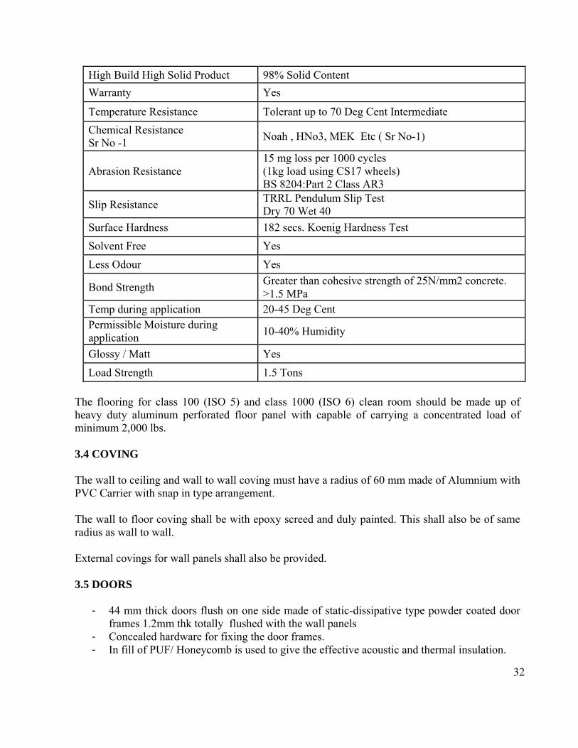
Self Leveling Type Epoxy flooring 3 mm thick over leveled surface and smoothened with primer before laying of epoxy. Following shall be the properties of the epoxy paint system. Flooring shall be scratch proof and resistant to common lab solvents and chemicals. The flooring shall provide seamless finish.
32
High Build High Solid Product 98% Solid Content
Warranty Yes
Temperature Resistance Tolerant up to 70 Deg Cent Intermediate
Chemical Resistance Sr No -1
Noah , HNo3, MEK Etc ( Sr No-1)
Abrasion Resistance 15 mg loss per 1000 cycles (1kg load using CS17 wheels) BS 8204:Part 2 Class AR3
Slip Resistance TRRL Pendulum Slip Test Dry 70 Wet 40
Surface Hardness 182 secs. Koenig Hardness Test
Solvent Free Yes
Less Odour Yes
Bond Strength Greater than cohesive strength of 25N/mm2 concrete. >1.5 MPa
Temp during application 20-45 Deg Cent Permissible Moisture during application
10-40% Humidity
Glossy / Matt Yes
Load Strength 1.5 Tons
The flooring for class 100 (ISO 5) and class 1000 (ISO 6) clean room should be made up of heavy duty aluminum perforated floor panel with capable of carrying a concentrated load of minimum 2,000 lbs. 3.4 COVING The wall to ceiling and wall to wall coving must have a radius of 60 mm made of Alumnium with PVC Carrier with snap in type arrangement. The wall to floor coving shall be with epoxy screed and duly painted. This shall also be of same radius as wall to wall. External covings for wall panels shall also be provided. 3.5 DOORS
- 44 mm thick doors flush on one side made of static-dissipative type powder coated door frames 1.2mm thk totally flushed with the wall panels
- Concealed hardware for fixing the door frames. - In fill of PUF/ Honeycomb is used to give the effective acoustic and thermal insulation.
33
- Stainless steel double bearing butt hinges as per BS 7352 CLASS 9. - Mortise dead locks .
3.6 LIGHTS Sufficient fluorescent lighting, in accordance with required class of clean room shall be fitted to on the ceiling to provide light intensity level of 500 lux at 1 meter above the clean room floor for all labs and for corridor / service area 300 lux. Lights incorporated within the FFUs to meet the luminance specification are also considered.
- Clean room light fittings of size 2’x2’ shall be installed - Fitting shall be with opal acrylic cover with powder coated aluminium grid to provide
flush finish from clean room side. - Lights shall be outside clean room side serviceable type.(except BSL & organic chemistry
Lab) - Luminaire shall be 3x36W CFL or better.
For class 1000 (ISO 6) and Class 100 (ISO 5) clean rooms, tear drop light fixtures shall be installed, since tear drop light fixture having flow through lights are designed to reduce turbulence in the cleanrooms that require a unidirectional air flow. 3.7 VIEW PANELS
- View panels of size 900x900 mm shall be provided in wall panels - View panels glass shall be at least 5 mm thick. - View panels shall be fixed flush to both faces of wall panels. - No crevices / joints/sloped profiles are used for fixing the glass to avoid particle
contamination and dust accumulation.
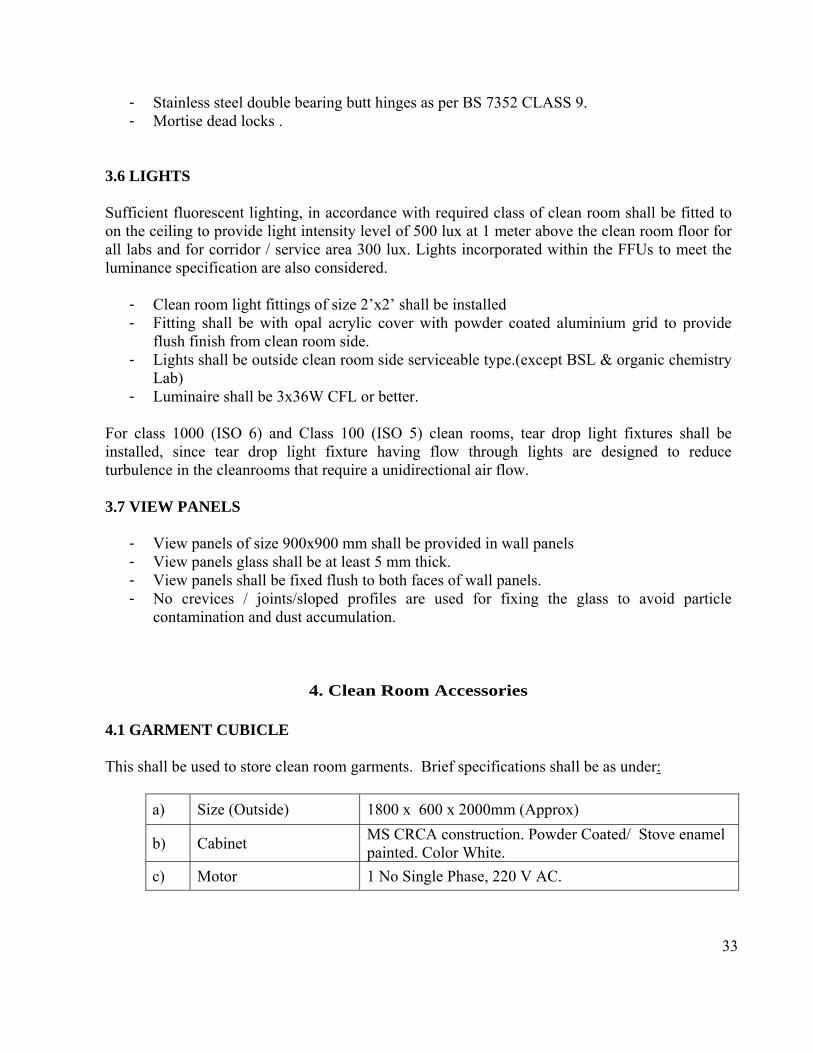
4. Clean Room Accessories 4.1 GARMENT CUBICLE This shall be used to store clean room garments. Brief specifications shall be as under:
a) Size (Outside) 1800 x 600 x 2000mm (Approx)
b) Cabinet MS CRCA construction. Powder Coated/ Stove enamel painted. Color White.
c) Motor 1 No Single Phase, 220 V AC.
34
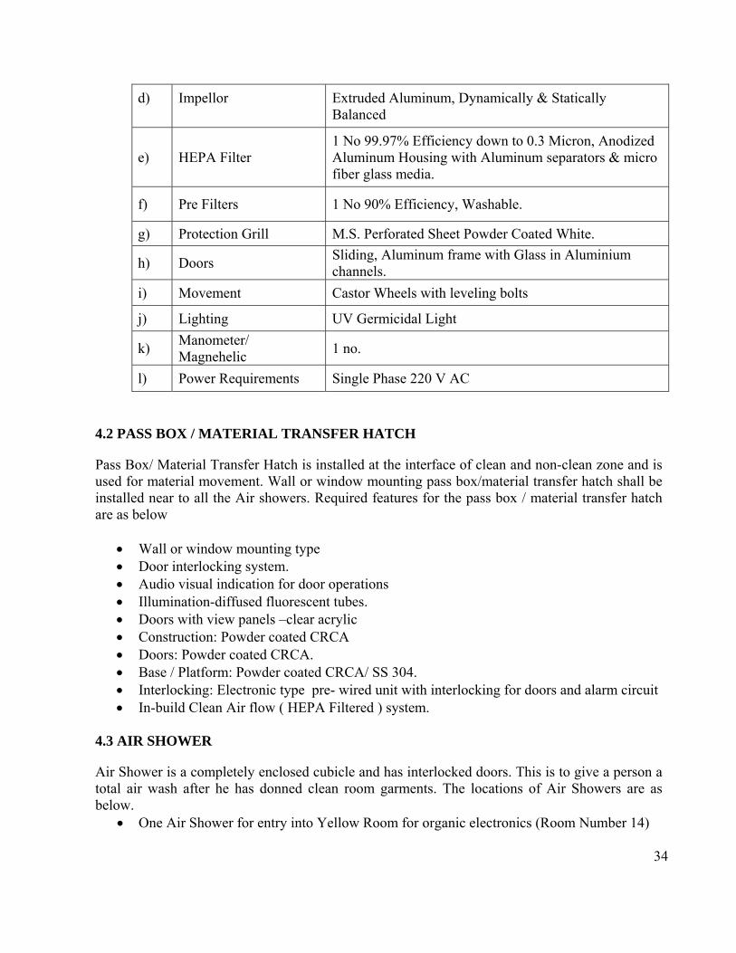
d) Impellor
Extruded Aluminum, Dynamically & Statically Balanced
e) HEPA Filter 1 No 99.97% Efficiency down to 0.3 Micron, Anodized Aluminum Housing with Aluminum separators & micro fiber glass media.
f) Pre Filters 1 No 90% Efficiency, Washable.
g) Protection Grill M.S. Perforated Sheet Powder Coated White.
h) Doors Sliding, Aluminum frame with Glass in Aluminium channels.
i) Movement Castor Wheels with leveling bolts
j) Lighting UV Germicidal Light
k) Manometer/ Magnehelic
1 no.
l) Power Requirements Single Phase 220 V AC
4.2 PASS BOX / MATERIAL TRANSFER HATCH
Pass Box/ Material Transfer Hatch is installed at the interface of clean and non-clean zone and is used for material movement. Wall or window mounting pass box/material transfer hatch shall be installed near to all the Air showers. Required features for the pass box / material transfer hatch are as below
Wall or window mounting type Door interlocking system. Audio visual indication for door operations Illumination-diffused fluorescent tubes. Doors with view panels –clear acrylic Construction: Powder coated CRCA Doors: Powder coated CRCA. Base / Platform: Powder coated CRCA/ SS 304. Interlocking: Electronic type pre- wired unit with interlocking for doors and alarm circuit In-build Clean Air flow ( HEPA Filtered ) system.
4.3 AIR SHOWER
Air Shower is a completely enclosed cubicle and has interlocked doors. This is to give a person a total air wash after he has donned clean room garments. The locations of Air Showers are as below.
One Air Shower for entry into Yellow Room for organic electronics (Room Number 14)
35
One Air Shower for entry into Corridor adjacent to SEM lab One Air Shower for entry into Class 1000 (ISO 6) lab
Each Air shower shall have proximity card reader. All the air-shower should be able to open only after successfully verification / validation of proximity type card reader access system validates the authorization for the person / proximity card The Air Shower comprises of a set of Pre-filters through which all air is sucked in and then passes through a set of Pre-filters and then HEPA Filters before it is forced onto the personnel standing inside. The person gets the air through a set of nozzles from two sides and the top. To maintain the effectiveness of the unit the Air Shower has 2 separate blowers on each side. a) Size (Outside) 1350 x 1000 x 2200mm (Approx)
b) Cabinet MS CRCA construction. Powder Coated / Stove enamel painted. Color White.
c) Motor 2 No Three/ Single Phase AC.
d) HEPA Filter 2 No 99.97% Efficiency down to 0.3 Micron, Anodized Aluminum Housing with Aluminum separators & micro fiber glass media.
e) Pre Filters 2 No 90% Efficiency, Washable.
f) Protection Grill M.S. Perforated Sheet Powder Coated White.
g) Doors Hinged type, double skin type with flush view panel
h) Door Interlocking Door opening with solid state electronic inter locking, at a time only one door can be opened
i) Shower duration 0 to 120 seconds – digitally settable / adjustable.
j) Access Control Air shower shall have proximity type card reader. Only authorized persons verified by proximity type card reader access system should able to enter the air – showers.
4.4 Fume Hood 4.4.1 Location The locations of Fume Hood and quantity needs to be installed in the clean room are given in below table.
Sr No. Name of Location Room number Quantity Type
1 Yellow Room for Organic Electronics–2
14 2 Fume Hood
36
2 Sub-fab 10’ (GF) 1 Fume Hood
3 Sub Fab 9’ (GF) 2 HF Resistant Fume Hood
4 Class 1000 (ISO 6) 9P (FF) 2 Clean room Wet bench
5 BSL 2 17 2 BSC Class II fume hood The exhaust of fume hoods / wet-benches must pass through the fume scrubber and neutralizing tank. The electrical circuit / sockets of each fume hood should be protected by MCBs 4.4.2 Specification of Fume Hood All materials, including service fittings and exhaust systems, shall be resistant to the chemicals / solvents and shall be a fire-retardant grade. Coatings and finishes shall be fire resistant.
Workspace : 4’ W x 3’ D x 3½’H (approx) Mounting type : Floor mounted type Hood face velocity: 60 ft/min to 150 ft/min adjustable type. Construction Design: Double Skin Type Interior Lighting: Illuminated by a vapor proof incandescent light fixture containing
minimum two fluorescent lights and about 500 lux intensity at worktop level. Front Top Panel : Easily open-able hinged top panel for easy access to flow control valve
and electrical lighting fixtures for maintenance. Corner Post: Triangular profiled corner post shall be placed on left and right hand side of
the fume hood and it houses the utility line fittings and electrical receptacles. Interior construction: Chemical & heat resistant, fire retardant, smooth finish and easily
cleanable panels Door : Sliding type front door with polycarbonate sash Work area: Work area surfaces shall be non-porous, non-conductive, thermal and scratch
resistant. Worktop shall be splash and spillage proof Air Flow regulators: 2 quantities of air flow regulators (CDA and N2) Wet and Dry service valves : Remotely operated colour coded valves for fine control over
utilities (as per DIN 12920 norms), total 3 nos. service valves with stainless steel tubing with 6 mm internal dia, withstands up to 15 kgf pressure and brass fittings for gas connections. All the wet and dry service valves [ a) 1 for Raw water, b) 1 for Nitrogen and 3) 1 for Vacuum] shall be on the left hand side.
Maintenance ports : Openable top panel for easy maintenance of tube light and flow control valve. Triangular service panel for maintenance of utility valves and tubing.
Sink: A sink with on the worktop shall have drainage with water top on left side of worktop. Sink shall be chemical and corrosion resistant. Sink shall have a trap for waste collection / drain arrangement.
Shutter : Vertical rising shutter counter-balanced with pulley and counter-weight system. Breaking stress value for fully toughened glass (tempered glass) shall be 24,000 psi
Base Cabinets: Fume Hood shall contain acid resistant base cabinets with locking system

37
Electrical utilities: Minimum 2 quantity of 230V, 15 Amp, 50Hz single phase electrical sockets (Indian standard) on the fume hood, in which 1000 watts heater / hot water bath and 1000 watts inductive load / magnetic stirrers etc., may be connected by the user. Each electrical socket shall have independent ON/OFF switches as well as MCB. Cables and wires shall be fire retardant grade. All electrical utilities shall be on the right hand side.
Control Panel: For turn ON/OFF of internal lights, adjust the hood face velocity and switching the exhaust fan on or off.
Air Flow monitor: This device is an accessory for fume hood to indicate the approximate face velocity of airflow with primary purpose of warning when a low flow condition occurs. Red & green LEDs correspond to low & normal flow rates respectively. When flow decreases from normal to low, an audible alarm will also actuate requiring manual acknowledgement for silence. Digital display of face velocity in m/sec or fpm. On screen display for safe and alarm conditions with audible alarm and LED indication. Push button calibration and configuration. Plug-in connections for power supply and airflow sensor.
Auto fire extinguisher: Fire extinguisher to take care of fire erupting within the fume hood. The sensing tube/sensor will activate immediately after fire breaks out within the hood. Sensor threshold : 68 degree centigrade. Media: ABC Dry Powder.
Level adjusting screws: Made of SS Bolts to adjust the fume hood level by ± 10 mm. Exhaust Port: Unique exhaust port design ensures that the fumes will be exhausted
smoothly without any turbulence at the exhaust port. Also it shall ensure low noise level. Noise level : < 70 db at 1 meter from fume hood. Blower: For air suction in the fume hood, efficient remote centrifugal blower and
chemical resistant impeller. Ducting: chemical resistant ductwork from fume hood to exhaust stack point with
weatherproof canopy. 4.4.3 Specification of HF Resistant Fume Hood Same as 4.4.2 except the materials for construction should be resistant to hydro fluoric acid (HF) and the duct as well as exhaust blowers/fan should be resistant to HF vapors. 4.4.4 Specification of Wet Benches Features
Manual modular wet process station, configurable for wet strip and clean applications Recirculating filtered process tank option and Quick dump rinse (QDR) Capable of processing wafer boats 4"/5"/6”containing 25 wafers. Leak-checked prior to factory acceptance and shipment Reinforced transparent side and eye shields System is engineered to achieve 100 to 150 linear feet per minute of face exhaust velocity
when specific volumetric exhaust flow is provided by facility to protect operator and system components from harmful vapors
Easily removable deck top for maintenance and serviceability Head case door hinges manufactured of compatible non-metal material.
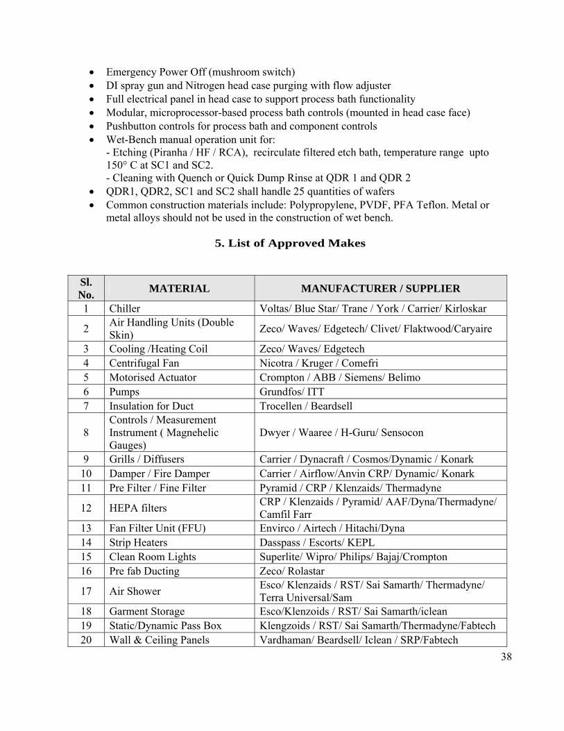
38
Emergency Power Off (mushroom switch) DI spray gun and Nitrogen head case purging with flow adjuster Full electrical panel in head case to support process bath functionality Modular, microprocessor-based process bath controls (mounted in head case face) Pushbutton controls for process bath and component controls Wet-Bench manual operation unit for:
- Etching (Piranha / HF / RCA), recirculate filtered etch bath, temperature range upto 150° C at SC1 and SC2. - Cleaning with Quench or Quick Dump Rinse at QDR 1 and QDR 2
QDR1, QDR2, SC1 and SC2 shall handle 25 quantities of wafers Common construction materials include: Polypropylene, PVDF, PFA Teflon. Metal or
metal alloys should not be used in the construction of wet bench.
5. List of Approved Makes
Sl. No.
MATERIAL MANUFACTURER / SUPPLIER
1 Chiller Voltas/ Blue Star/ Trane / York / Carrier/ Kirloskar
2 Air Handling Units (Double Skin)
Zeco/ Waves/ Edgetech/ Clivet/ Flaktwood/Caryaire
3 Cooling /Heating Coil Zeco/ Waves/ Edgetech 4 Centrifugal Fan Nicotra / Kruger / Comefri 5 Motorised Actuator Crompton / ABB / Siemens/ Belimo 6 Pumps Grundfos/ ITT 7 Insulation for Duct Trocellen / Beardsell
8 Controls / Measurement Instrument ( Magnehelic Gauges)
Dwyer / Waaree / H-Guru/ Sensocon
9 Grills / Diffusers Carrier / Dynacraft / Cosmos/Dynamic / Konark 10 Damper / Fire Damper Carrier / Airflow/Anvin CRP/ Dynamic/ Konark 11 Pre Filter / Fine Filter Pyramid / CRP / Klenzaids/ Thermadyne
12 HEPA filters CRP / Klenzaids / Pyramid/ AAF/Dyna/Thermadyne/ Camfil Farr
13 Fan Filter Unit (FFU) Envirco / Airtech / Hitachi/Dyna 14 Strip Heaters Dasspass / Escorts/ KEPL 15 Clean Room Lights Superlite/ Wipro/ Philips/ Bajaj/Crompton 16 Pre fab Ducting Zeco/ Rolastar
17 Air Shower Esco/ Klenzaids / RST/ Sai Samarth/ Thermadyne/ Terra Universal/Sam
18 Garment Storage Esco/Klenzoids / RST/ Sai Samarth/iclean 19 Static/Dynamic Pass Box Klengzoids / RST/ Sai Samarth/Thermadyne/Fabtech 20 Wall & Ceiling Panels Vardhaman/ Beardsell/ Iclean / SRP/Fabtech

39
21 Clean Room Doors Synergy/Metaflex/ Metachno/ Beardsell/ SRP/Fabtech
22 BMS System Controller/ Router
Automated Logic Corporation / carrier make / Siemens / Honeywell/Sauter
23 Fume Hood LabGuard/Dynaflow / BMC/ Esco Micro
24 Wet benches Terra Universal/Micro Tech/ Amerimade/MEI/ Applied Physic Inc
27 Aluminium Honeycomb core wall panels
Portafab/Plascore/Alcore/Universal Metal Tex/Amber composites
28 Cables and wires Finolex/National/Delton/Ecko/Havels/Cord 29 Switches/Sockets/MCB/MCCB Anchor/Alstom/Siemens/Legrand/Havells
6. Installation and Training Clean rooms' mechanical assembly shall be done by the Supplier.
Electrical system installation shall be done by qualified and authorized electrician employed or subcontracted by the Supplier.
The clean room fire safety system shall be installed by the Supplier's licensed and certified fire
safety sub‐tier supplier after approval by the NCNNUM
Supplier has to arrange for materials unloading and staging. Any damage to the NCNNUM equipments or building structure shall be borne by the supplier.
The Supplier shall provide full training on the clean rooms' operations, equipment preventive maintenance and repair. Final documentation shall include the training manuals. Operation and maintenance manuals should be provided by the supplier.
7. Acceptance and Completion
The supplier shall install and commission all utilities covered under the contract and demonstrate performance and quality parameters of the cleanrooms/equipments/systems/networks at the rated capacity/as per design. The Supplier shall supply clean room certifications complying with ISO 14644 requirements. Following Performance tests shall be carried out in three occupancy states:
as‐built, at‐rest and operational:
a) Air borne particle count for ultrafine particles
b) Airborne particle count for macro-particles
c) Airflow test, air velocity measurement, leakage test, room pressurization test.
40
d) Air pressure difference test
e) Installed filter system leakage test
f) Airflow direction test and visualization using fog generator
g) Temperature test
h) Humidity test
i) Electrostatic and ion generator test
j) Particle deposition test
k) Recovery test
l) Containment leak test
m) Illumination level measurement according to DIN 5035.
NCNNUM Personnel shall witness the performance tests.
The order is considered to be complete when all of the following are satisfied:
a) The supplier has completed all construction and assembly to specification as mentioned in Part B.
b) All HVAC, electrical systems, intercom and LAN points to be tested and activated.
c) The fire protection system, Building Management System (BMS) and biometric / proximity access control systems has been tested and activated.
d) Acceptance tests have been completed and are satisfactory
Sd/- Director, NCNNUM, University of Mumbai

41
Annexure ‘A’ – Layout of clean room

42
Annexure ‘B’ – Layout of Satellite clean room (ISO – 8) facility as optional
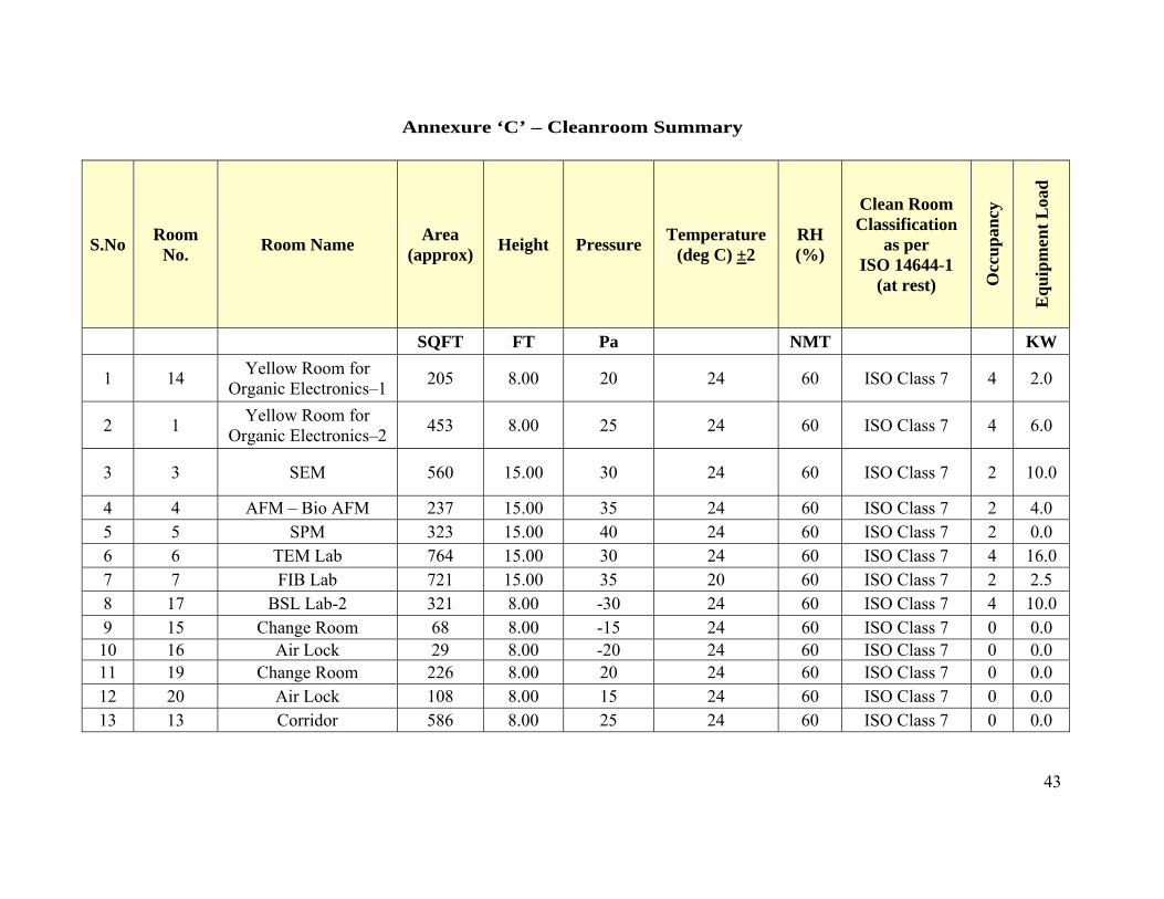
43
Annexure ‘C’ – Cleanroom Summary
S.No Room
No. Room Name
Area (approx)
Height Pressure Temperature
(deg C) ±2 RH (%)
Clean Room Classification
as per ISO 14644-1
(at rest) Occ
up
ancy
Eq
uip
men
t L
oad
SQFT FT Pa NMT KW
1 14 Yellow Room for
Organic Electronics–1 205 8.00 20 24 60 ISO Class 7 4 2.0
2 1 Yellow Room for
Organic Electronics–2 453 8.00 25 24 60 ISO Class 7 4 6.0
3 3 SEM 560 15.00 30 24 60 ISO Class 7 2 10.0
4 4 AFM – Bio AFM 237 15.00 35 24 60 ISO Class 7 2 4.0 5 5 SPM 323 15.00 40 24 60 ISO Class 7 2 0.0 6 6 TEM Lab 764 15.00 30 24 60 ISO Class 7 4 16.0 7 7 FIB Lab 721 15.00 35 20 60 ISO Class 7 2 2.5 8 17 BSL Lab-2 321 8.00 -30 24 60 ISO Class 7 4 10.0 9 15 Change Room 68 8.00 -15 24 60 ISO Class 7 0 0.0 10 16 Air Lock 29 8.00 -20 24 60 ISO Class 7 0 0.0 11 19 Change Room 226 8.00 20 24 60 ISO Class 7 0 0.0 12 20 Air Lock 108 8.00 15 24 60 ISO Class 7 0 0.0 13 13 Corridor 586 8.00 25 24 60 ISO Class 7 0 0.0

44
S.No Room
No. Room Name
Area (approx)
Height Pressure Temperature
(deg C) ±2 RH (%)
Clean Room Classification
as per ISO 14644-1
(at rest) Occ
up
ancy
Eq
uip
men
t L
oad
14 8 Surface Analytical Lab 284 15.00 30 24 60 ISO Class 7 3 10.0
15 9 MBE 261 15.00 30 24 60 ISO Class 7 2 4.0 16 10 PED PLD 156 15.00 30 24 60 ISO Class 7 2 4.0 17 9'+9P 9'(GF)+9P(FF) 216 17.00 40 24 45 ISO Class 6 4 15.0 18 10'+10P 10'(GF)+10P(FF) 130 17.00 40 24 45 ISO Class 5 4 2.0 19 11 Air Lock 33 8.00 20 24 60 ISO Class 7 0 0.0
20 18 BMS Control Room 88 12.00 0 24 60 Unclassified 1 0.0
21 12 Service Area for PED
PLD Lab 496 12.00 0 24 60 Unclassified 1 4.0
22 2 Service Area 130 8.00 0 24 60 Unclassified 1 0.0 NOTE: 1. Lighting load is to be taken ≥ 1.5 W / sft of room area. 2 .Consider min 2 Fresh Air changes per hour 3. For infilteration / Ex filtration air calculation, Door gap if 3mm all around the door is taken.
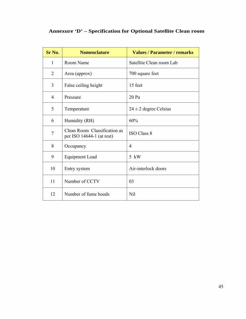
45
Annexure ‘D’ – Specification for Optional Satellite Clean room
Sr No. Nomenclature Values / Parameter / remarks
1 Room Name Satellite Clean room Lab
2 Area (approx) 700 square feet
3 False ceiling height 15 feet
4 Pressure 20 Pa
5 Temperature 24 ± 2 degree Celsius
6 Humidity (RH) 60%
7 Clean Room Classification as per ISO 14644-1 (at rest)
ISO Class 8
8 Occupancy 4
9 Equipment Load 5 kW
10 Entry system Air-interlock doors
11 Number of CCTV 03
12 Number of fume hoods Nil
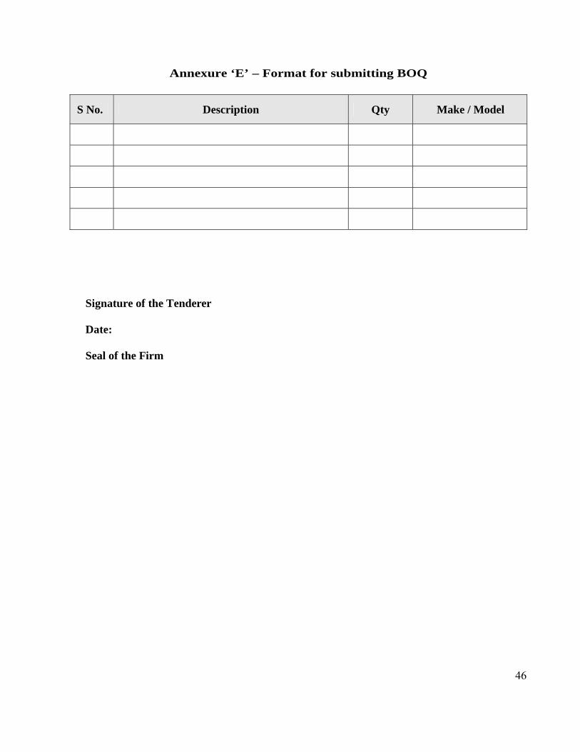
46
Annexure ‘E’ – Format for submitting BOQ
S No. Description Qty Make / Model
Signature of the Tenderer Date: Seal of the Firm

47
Annexure ‘F’ – Format for submitting compliance/response of bidder With reference to the technical details described in different sections of Part B, the bidder shall provide their compliance/response as below format and signature of bidder with company seal at the end of each page. Section Number
Nomenclature Bidder’s Compliance /
Response 1 Design Philosophy & Technical Details
1.1 Facility layout 1.2 The construction of the facility 1.3 The HVAC system 1.4 The building management system 1.5 Lab Electrification 1.6 Fire detection system 1.7 Door interlocks and access control for entry to labs 1.8 Clean Room Accessories 1.9 Voice and LAN data communication 1.10 CCTV Camera 1.11 Validation of the labs 1.12 Lab validation
1.13 Requirement of facilities to be considered in the layout
1.14 Brief summary of scope of tender / job 1.1.5 Supplies 1.16 Documentation
2 Heating Ventilation & Air Conditioning Work 2.1 Floor mounted air handling units 2.2 Supply air and HEPA plenums 2.3 Dampers 2.4 Filters 2.5 Electrical control panel 2.6 Ducting 2.7 Caulking 2.8 Insulation 2.9 Application 3 Clean Room & Civil Finishes
3.1 Ceiling 3.2 Wall paneling system 3.3 Flooring 3.4 Coving 3.5 Doors 3.6 Lights 3.7 View panels
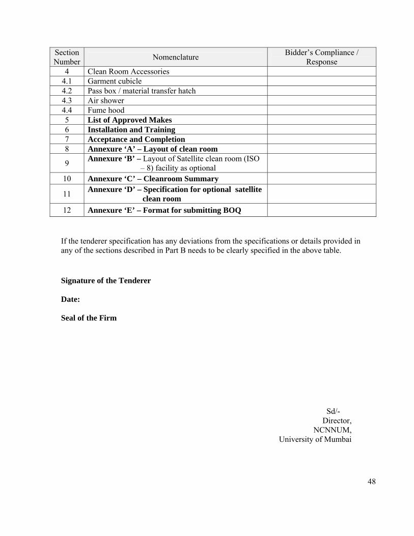
48
Section Number
Nomenclature Bidder’s Compliance /
Response 4 Clean Room Accessories
4.1 Garment cubicle 4.2 Pass box / material transfer hatch 4.3 Air shower 4.4 Fume hood 5 List of Approved Makes 6 Installation and Training 7 Acceptance and Completion 8 Annexure ‘A’ – Layout of clean room
9 Annexure ‘B’ – Layout of Satellite clean room (ISO – 8) facility as optional
10 Annexure ‘C’ – Cleanroom Summary
11 Annexure ‘D’ – Specification for optional satellite clean room
12 Annexure ‘E’ – Format for submitting BOQ
If the tenderer specification has any deviations from the specifications or details provided in any of the sections described in Part B needs to be clearly specified in the above table. Signature of the Tenderer Date: Seal of the Firm
Sd/- Director,
NCNNUM, University of Mumbai