Construction Manual 07 Concrete Pavements 2012
45
CONCRETE PAVEMENTS AND SHOULDERS DIVISION 7 North Carolina Department of Transportatio n Page 1 SECTION 700 GENERAL REQUIREMENTS FOR PORTLAND CEMENT CONCRETE PAVING......................................................................................................... 1 700-1 DESCRIPTION................................................................................................... 1 700-2 CONCRETE PRODUCTION EQUIPMENT ....................................................... 2 (A) CONC RETE PLANT INSPECTION - GENER AL ........................................... 2 (B) SPECIFIC REQUIREMENTS FOR BATCH PLANT INSPECTION ............... 4 (C) SPECIFIC REQUIREMENTS FOR CENTRAL MIX PLANT INSPECTION ... 5 700-3 CONCRETE HAULING EQUI PMENT ............................................................... 5 700-4 PREPARATION OF SUBGRAD E AND BASE .................................................... 5 700-5 PLACING CON CRETE ...................................................................................... 6 700-6 VIBR ATING CONCRETE ................................................................................... 7 700-7 FINI SHING ........................................................................................................ 8 700-8 PROTECTION OF PORTLAND CEMENT CONCRETE PAVEMENT ...... ...... .... 8 (A) GENERAL ..................................................................................................... 8 (B) COLD WEATHER ......................................................................................... 8 (C) HOT WEATHER ...... ................... ...... ........... ...... ..................................... ...... . 9 (D) RAIN ................................ ...... ................... ...... ........... ...... .................. ...... ..... 9 700-9 CURI NG............................................................................................................. 9 (A) GENERAL ..................................................................................................... 9 (B) MEMBRANE CURING COMPOUND ........ ............ ....... ..... ............ ...... ......... 9 (C) POLYETHYLENE FILM ............ ...... ..................................... ...... ........... ...... .10 (D) BURLAP ............ ...... ............ ..... ................... ...... ........... ...... ............ ....... ...... .10 700-10 REMOV ING FORMS .......................................................................................10 700-11 JOINT CONSTRUCTION ................................................................................10 (A) GENERAL ....................................................................................................10 (B) TRANSVERSE CONTRACTION JOINTS ......................................................12 (C) LONGITUDINAL CONTRACTION JOINTS ................... ...... ........... ...... .......12 (D) TRANSVERSE CONST RUCTION JOINTS ....................................................13 (E) LONGITUDINAL CONSTRUCTION JOINTS .................................... ...... .....13 (F) TRANSVERSE EXPANSI ON JOINT S ............................................................14 VERIFI CATION OF DOWEL BAR ALIGNM ENT ..................................................14 700-12 SEALI NG JOINTS ...........................................................................................17 (A) GENERAL ....................................................................................................17 (B) AGE OF PAVEMENT .................................... ...... .................................... .....17 (C) TEMPERATURE...........................................................................................18 (D) SEALING THE JOINT ..................................................................................18 (E) CLEANI NG PAVEMENT ..............................................................................18 700-13 USE OF NEW PAVEMENT OR SHOULDER ..................................................18 700-14 CONTRACTOR'S RESPONSIBILITY FOR P ROCESS CONTROL .................. .19 700-15 ACCEPTANCE TESTS FOR CON CRETE .......................................................19 (A) RESPONSIBILITY ......... ............. ...... .................................... ...... ............ ...... 19 (B) LOT DEFINITION ...... ................... ...... ........... ...... .................................... ....19 (C) AIR CONTENT ...... ................... ...... ........... ...... .................. ...... ................... ..19 (D) SLUMP.........................................................................................................20 (E) COMPRESSIVE STRENGTH ........................................................................20 (F) THICKNESS .................................................................................................21 (G) SURFACE SMOOTHNESS ...........................................................................21
-
Upload
mahendranmahe -
Category
Documents
-
view
216 -
download
0
Transcript of Construction Manual 07 Concrete Pavements 2012

8/13/2019 Construction Manual 07 Concrete Pavements 2012
http://slidepdf.com/reader/full/construction-manual-07-concrete-pavements-2012 1/45
CONCRETE PAVEMENTS AND SHOULDERS DIVISION 7
North Carolina Department of Transportation Page 1
SECTION 700 GENERAL REQUIREMENTS FOR PORTLAND CEMENT
CONCRETE PAVING ......................................................................................................... 1 700-1 DESCRIPTION................................................................................................... 1 700-2 CONCRETE PRODUCTION EQUIPMENT ....................................................... 2
(A) CONCRETE PLANT INSPECTION - GENERAL ........................................... 2 (B) SPECIFIC REQUIREMENTS FOR BATCH PLANT INSPECTION ............... 4 (C) SPECIFIC REQUIREMENTS FOR CENTRAL MIX PLANT INSPECTION ... 5
700-3 CONCRETE HAULING EQUIPMENT ............................................................... 5 700-4 PREPARATION OF SUBGRADE AND BASE .................................................... 5 700-5 PLACING CONCRETE ...................................................................................... 6 700-6 VIBRATING CONCRETE ................................................................................... 7 700-7 FINISHING ........................................................................................................ 8 700-8 PROTECTION OF PORTLAND CEMENT CONCRETE PAVEMENT ................ 8
(A) GENERAL ..................................................................................................... 8 (B) COLD WEATHER ......................................................................................... 8 (C) HOT WEATHER ............................................................................................ 9 (D) RAIN ................................ ............................................................................. 9 700-9 CURING............................................................................................................. 9 (A) GENERAL ..................................................................................................... 9 (B) MEMBRANE CURING COMPOUND ........................................................... 9 (C) POLYETHYLENE FILM ...............................................................................10 (D) BURLAP ................................................................................................ .......10
700-10 REMOVING FORMS .......................................................................................10 700-11 JOINT CONSTRUCTION ................................................................................10
(A) GENERAL ....................................................................................................10 (B) TRANSVERSE CONTRACTION JOINTS ......................................................12 (C) LONGITUDINAL CONTRACTION JOINTS .................................................12 (D) TRANSVERSE CONSTRUCTION JOINTS ....................................................13 (E) LONGITUDINAL CONSTRUCTION JOINTS ...............................................13 (F) TRANSVERSE EXPANSION JOINTS ............................................................14 VERIFICATION OF DOWEL BAR ALIGNMENT ..................................................14
700-12 SEALING JOINTS ...........................................................................................17 (A) GENERAL ....................................................................................................17 (B) AGE OF PAVEMENT ...................................................................................17 (C) TEMPERATURE...........................................................................................18 (D) SEALING THE JOINT ..................................................................................18 (E) CLEANING PAVEMENT ..............................................................................18
700-13 USE OF NEW PAVEMENT OR SHOULDER ..................................................18 700-14 CONTRACTOR'S RESPONSIBILITY FOR PROCESS CONTROL ...................19
700-15 ACCEPTANCE TESTS FOR CONCRETE .......................................................19
(A) RESPONSIBILITY ................................................................ ........................19 (B) LOT DEFINITION ........................................................................................19 (C) AIR CONTENT .............................................................................................19 (D) SLUMP .........................................................................................................20 (E) COMPRESSIVE STRENGTH ........................................................................20 (F) THICKNESS .................................................................................................21 (G) SURFACE SMOOTHNESS ...........................................................................21

8/13/2019 Construction Manual 07 Concrete Pavements 2012
http://slidepdf.com/reader/full/construction-manual-07-concrete-pavements-2012 2/45
CONCRETE PAVEMENTS AND SHOULDERS DIVISION 7
North Carolina Department of Transportation Page 2
TECHNICIAN'S CHECKLIST SECTION 700 CONCRETE PAVEMENTS ANDSHOULDERS....................................................................................................................... 22 SECTION 710 CONCRETE PAVEMENT ........................................................................28
710-1 DESCRIPTION..................................................................................................28 710-2 MATERIALS ......................................................................................................28 710-3 COMPOSITION OF CONCRETE......................................................................28 710-4 ACCEPTANCE OF CONCRETE .......................................................................28 710-5 CONSTRUCTION METHODS...........................................................................29 710-6 FINISHING .......................................................................................................29 710-7 FINAL SURFACE TESTING .............................................................................33 710-8 PAVEMENT MARKING ....................................................................................34 710-9 THICKNESS TOLERANCES .............................................................................34 710-10 MEASUREMENT AND PAYMENT ..................................................................34
(A) GENERAL ....................................................................................................34 (B) PAVEMENT DEFICIENT IN THICKNESS ...................................................34 (C) CONCRETE PAVEMENT VARYING IN STRENGTH ...................................35
TECHNICIAN'S CHECKLIST SECTION 710 CONCRETE PAVEMENTS ANDSHOULDERS....................................................................................................................... 35 SECTION 720 CONCRETE SHOULDERS ......................................................................36
720-1 DESCRIPTION..................................................................................................36 720-2 MATERIALS ......................................................................................................36 720-3 COMPOSITION OF CONCRETE......................................................................36 720-4 ACCEPTANCE OF CONCRETE .......................................................................36 720-5 EQUIPMENT ....................................................................................................36 720-6 CONSTRUCTION METHODS...........................................................................36 720-7 FINISHING .......................................................................................................37 720-8 JOINTS .............................................................................................................37
720-9 THICKNESS TOLERANCES .............................................................................37 720-10 MEASUREMENT AND PAYMENT ..................................................................37
SECTION 725 FIELD LABORATORY FOR PORTLAND CEMENT CONCRETE
PAVEMENT........................................................................................................................38 725-1 DESCRIPTION..................................................................................................38 725-2 GENERAL REQUIREMENTS ............................................................................38 725-3 COMPENSATION .............................................................................................38
TECHNICIAN'S CHECKLIST SECTION 700 PORTLAND CEMENT CONCRETE
PAVEMENT PART 1 - PLANT INSPECTION ................................................................ 39 TECHNICIAN'S CHECKLIST SECTION 700 PORTLAND CEMENT CONCRETE
PAVEMENT PART II - ROADWAY INSPECTION ....................................................... 41

8/13/2019 Construction Manual 07 Concrete Pavements 2012
http://slidepdf.com/reader/full/construction-manual-07-concrete-pavements-2012 3/45
7-1
DIVISION 7
CONCRETE PAVEMENTS AND SHOULDERS
SECTION 700
GENERAL REQUIREMENTS FOR PORTLAND CEMENT CONCRETE PAVING
700-1 DESCRIPTION
The Specifications provide for the use of any reasonable equipment or methods which will produce acceptable work. The Specifications further require inspection and approval of the
Contractor's equipment by the Engineer prior to the beginning of work. The Engineer shouldcontact the Pavement Construction Section of the Construction Unit to request assistance prior to
this inspection and approval.The Specifications require that all equipment be maintained in satisfactory operating
condition. Frequent breakdowns may be a reason for the Engineer to shut down pavingoperations until the equipment is operating satisfactorily. It may be impractical for the Engineer
to actually detect the operating condition of the various pieces of equipment until paving has begun. Therefore, when it is known that the Contractor's plant or roadway equipment has
recently been on another highway project in the State, the Engineer on the previous projectshould be contacted and the performance of the equipment discussed to detect operating
characteristics, potential problem areas, etc.Due to the many variables in production and placement of concrete pavement and due to
the difficulty of repair or replacement of faulty work, this type of pavement demands an alert,well-informed inspection force under the constant attention of the Engineer or one individual
authorized by the Engineer to take any necessary immediate corrective actions required duringthe performance of the work.
Should the Engineer elect to delegate this authority, the authority should include thespecific authority to stop the work immediately when any non-conformity or detrimental
condition is found to exist and such condition is not immediately corrected by the Contractor
upon request. The Contractor must be informed by the Engineer of the delegation of authorityand to whom it is delegated.
The Contractor is required to submit a Process Control Plan for approval before placing
concrete pavement. This Process Control plan is typically submitted 3-6 months before the paving operations are scheduled to begin. The process control plan should identify the
operations and measures the Contractor is planning to take to ensure they are delivering a quality product. A detailed process control plan would identify specific individuals who are responsible
for performing the quality control operations necessary to complete the work satisfactorily, typesand frequency of testing, etc. to achieve an acceptable product without mimicking the Standard
Specifications. Article 1000-3(F) requires the Contractor to submit a process control planassociated with the concrete plant operations. The Pavement Construction Section as well as
Materials and Tests Unit should be involved in the approval of the process control plan.It should be further noted that the Construction Unit provides advisory service to the
Engineer on all concrete paving work. This service is available on both a spot check and on acall basis. The Engineer should fully utilize this service beginning with the Preconstruction
Conference.

8/13/2019 Construction Manual 07 Concrete Pavements 2012
http://slidepdf.com/reader/full/construction-manual-07-concrete-pavements-2012 4/45
7-2
700-2 CONCRETE PRODUCTION EQUIPMENT
(A) CONCRETE PLANT INSPECTION - GENERAL
The Technician at the batching plant or central mixing plant is responsible for ensuring
that all concrete materials comply with the Specifications, for their proper handling, and forensuring that the materials are weighed into batches of the proper size. He also is responsible for performing tests on cement (for air content) and making the test beams used for determining the
compressive strength of the concrete. Section 1000-3(F) indicates the Contractor's areas ofresponsibility for process control. The Technician should ensure that a copy of the Contractor's
approved process control plan is posted in the field laboratory and should be familiar with that plan. The Plant (Batch) and Roadway Technician as appropriate should accomplish minimum
sampling and testing indicated by the minimum sampling guide.The Standard Specifications permit the use of batch plants, central mix plants, and batch
plants with truck mixers in the production of concrete for concrete pavement. The requirementsfor batch plants, central mix plants, truck mixers and other specification requirements relating to
concrete production are included in Division 10 of the Standard Specifications. In addition, theMaterials and Tests Unit must certify the Contractor’s plant.
Although aggregates are inspected and approved at the point of manufacture or source, thePlant Technician must ensure that the materials, as used, continue to meet the Specifications and
have not become segregated or contaminated. The goal of the Technician at the plant should beto assure the production of concrete using the approved mix and ensuring and documenting that
the Contractor obtains the desired workability, slump, and strength.The Plant (Batch) Technician will also be required to keep records pertaining to materials
received, daily operations, and test results of materials tested.M&T Form 253P is to be completed by the Plant (Batch) Technician. The M&T Form
253L is to be completed by the Laboratory Technician. Both the Plant (Batch) and LaboratoryTechnicians are to submit daily their M&T 253 forms to the Roadway Technician. The Roadway
Technician is to complete the M&T Form 253R . The M&T Form 253 reports are to becompleted and submitted daily to the State Materials Engineer, even though some of the
information to be shown is a repetition of that previously shown and even when no pavement is placed, as when the paving operation is rained out. Procedures regarding this form can be found
in the Construction and Inspection of Portland Cement Concrete Pavement Manual.A field laboratory meeting the requirements of Section 725 of the Specifications is to be
furnished by the Contractor at the plant site. This laboratory should be located as close to the plant and stockpiles as is reasonable. The chamber for the water-lime storage tanks or the curing
shelter for test beams furnished by the Contractor should be next to and readily accessible to thelaboratory.
The Plant Technician will make 6 inch x 12 inch compressive test specimens inaccordance with Article 700-15. The cylinders are to be made, cured, and tested in accordance
with the procedures outlined in the Construction and Inspection of Portland Cement Concrete
Pavement Manual.
The Standard Specifications requires the Contractor to run moisture tests on theaggregates each morning before paving operations begin, and as often thereafter as necessary to
control the consistency of the concrete, with a minimum of 2 per day. The fine aggregateweights and course aggregate weights must be adjusted by the Contractor to account for the free
moisture in the aggregate. A description of how to run these moisture tests is given in the

8/13/2019 Construction Manual 07 Concrete Pavements 2012
http://slidepdf.com/reader/full/construction-manual-07-concrete-pavements-2012 5/45
7-3
Portland Cement Concrete Certification Study Guide. The Technician should periodicallyobserve the Contractor's testing procedures and document these observations in his daily report.
All concrete pavements are air-entrained; i.e., a certain amount of air in the form ofminute, non-connected air bubbles will be intentionally included in the concrete mix. This is
done by the use of an air-entraining agent. The mix design will be based on the inclusion of
5.0% air in the mix to which a tolerance of + l.5% is allowed by the Specifications. The PlantTechnician must test each car or each fourth truck tanker of cement received prior to use toensure that cement already containing an air-entraining agent is not used. This test procedure is
described in the Portland Cement Concrete Certification Study Guide. The Roadway Technicianwill keep the Plant Technician informed of the air content of the concrete based upon air testing
that he performs at the roadway and the Plant Technician will advise the Contractor's plantsuperintendent so that appropriate adjustments may be made. The air-entraining agent may be
measured automatically by dispenser, or may be measured by hand, and the agent should beadded to the water as it is introduced into the mix or to the sand rather than to the stone. If
measured automatically, the dispenser should be checked at least once each morning and onceeach afternoon to ensure the proper amount of agent is being dispensed.
Sampling of cement should be in accordance with the minimum sampling guide.It is preferable that batch bins be loaded from stockpiles rather than from cars; however, if
the Engineer authorizes the Contractor to load bins from cars, it shall be done continuously andnot alternated with loading from stockpiles. This is necessary in order that proper correction of
batch weights for moisture in the aggregate may be made.A checklist of some of the items to be observed or checked relative to aggregate stockpiles
is listed as follows:1. The area that the stockpile is expected to cover should be cleaned of vegetation, and a
minimum 75-millimeter (3-inch) layer of aggregate should be maintained over the entirearea. The pile should be built in such a manner as to minimize segregation and shall be well
drained.2. When stockpiles are built by crane or conveyer belt, the material should not be allowed to
drop free for more than 3 meters (10 feet) as larger pieces may fracture or the wind may blowaway finer particles, altering the gradation. To prevent this, the clam bucket should be
opened only a slight distance above the top of the pile, or if a conveyer is used, a chimneyshould be suspended below the end of the conveyer.
3. The lips on the clam bucket should fit tight enough to avoid spillage when placing aggregatesin the stockpile or transferring them to the aggregate bins.
4. Boards, burlap, etc., used for patching holes in aggregate cars will frequently be picked upwith the aggregates during unloading. These should be removed. Screens or "grizzlies" with
maximum 150-millimeters (6-inch) square openings may be placed on top of aggregate binsand also on the skip of the paver to catch foreign material not previously removed. The
screens should be cleaned several times daily or as needed.5. When stockpiles are depleted, the loader operator should be warned to leave a thin layer of
aggregate and not to include any foreign material when cleaning up the pile.
6. Operation of any vehicles on the piles should be avoided whenever possible. Tracked
vehicles particularly may break up the large size aggregates. Rubber-tired vehicles shouldnot be permitted to spin wheels on piles, as this will break up the aggregate with resulting
changes in gradation. Care should be exercised so no earth material is carried on thestockpiles by tires or tracks.
7. Whenever trucks travel on a stockpile, boards must be used. The boards, preferably oak,must be a minimum of 2 inches in thickness, at least 12 inches wider than the wheels and

8/13/2019 Construction Manual 07 Concrete Pavements 2012
http://slidepdf.com/reader/full/construction-manual-07-concrete-pavements-2012 6/45
7-4
cleated to each other (salvaged bridge floor metal traffic treads have been used satisfactorilyinstead of boards).
8. Space should be left between stockpiles so that there will be no contamination of one sizeaggregate by another. In limited areas, adequate bulkheads should be placed between the
piles.
9.
It is important that fine and coarse aggregate be well graded and that the grading remainuniform throughout the life of the project. Visual examination should be made of theaggregate and stockpiles several times daily. The use of alternate wet and dry materials
direct from the quarry should not be permitted.
(B) SPECIFIC REQUIREMENTS FOR BATCH PLANT INSPECTION
In the operation of batch plants, it is essential that materials be accurately weighed into the batches. All batch weighing equipment should be supported on concrete footings. Before
starting a job, the scales shall be calibrated and checked for accuracy by a registered or licensedscale mechanic in the presence of the Plant Technician. The Materials and Tests Unit can
provide guidance in the proper performance of the scale check. A stamp of inspection andapproval shall be placed on the scales once approved. This should be done only after the bins
have been fully loaded for a period of 24 hours prior to checking. For calibration, the Contractorshall furnish ten standard 22.68-kilogram (50-pound) weights and sufficient personnel to assist in
making the scale test. A record of all calibration readings shall be kept on Form C2-1. After theinitial calibration, the scales are to be recalibrated after three to five days of operation and once a
week thereafter. At intervals of about one hour during batching, the scales should be checked bythe Technician to see that they balance at zero.
If the scales fail to balance at zero, this indicates the batches are not being weighedaccurately. This may mean that some material has remained in the hopper and is not being
discharged. Particular care should be taken to observe the cement scale because there is atendency for cement to cake in the corners of the hopper. The hopper should be adequately
vibrated. After vibration, if cement scales fail to balance on zero, the scales must be reset withthe main counterweight used for balancing the scales. It is very important that the correct
amount of cement is weighed out for each batch. If beam scales are used, the set screws holdingthe counterweights in position on the beam arms must be tightened firmly with pliers. Vibration
tends to move these weights and cause incorrect batching of materials.
Other items to be monitored and maintained:1. Scales must be kept level at all times.
2. All fulcrums, clevises, knife edges, and all working parts must be clean and free fromcement, dust, and dirt.
3. Never oil any working parts (this tends to collect dirt).4. The bin framework should be equipped with a canvas trunk that will prevent blowing and
consequent loss of cement during its transfer from hopper to truck. These trunks should be
of sufficient length to extend into the cement box to prevent any loss of cement.

8/13/2019 Construction Manual 07 Concrete Pavements 2012
http://slidepdf.com/reader/full/construction-manual-07-concrete-pavements-2012 7/45
7-5
(C) SPECIFIC REQUIREMENTS FOR CENTRAL MIX PLANT INSPECTION
Mixers used for central mixing should be checked before construction begins. Principal points to be observed include the following:
1.
The mixing blades should not be worn down more than 10 percent. If they are, theTechnician should require that they be built up or replaced.2. The water system should be tested at various settings of the water gauge and adjusted to
ensure proper readings.3. The mixer should be timed and the locking device in good working order to control the
mixing time.4. Valves should be checked for leakage.
5. The mixer should be checked frequently for build-up of set concrete on or around blades.6. The air-entraining agent dispenser should be checked for proper operation. The dispenser
and all piping should be maintained in a clean condition, and the air vent open to ensuredischarge of the desired amount of agent.
7.
The size of the batch, speed of rotation, and mixing cycle shall comply with theSpecifications.
700-3 CONCRETE HAULING EQUIPMENT
When central mixed concrete is used, the Plant Technician should check each truck for
compliance with the Specifications. All batch trucks should be inspected by the PlantTechnician before being permitted to be used on the project. The batch dividers should fit
tightly, and the compartments should be large enough to prevent any spillage during discharge.The Plant Technician and the Roadway Technician must both keep check on time and
length of haul. The time of haul, whether in agitating or non-agitating truck bodies, should notexceed the limits indicated in Article 700-3 of the Specifications. The elapsed time is defined as
the period from first contact between mixing water and cement until the entire operation of placing and finishing up to micro-surfacing (burlap drag, or Astroturf drag), including
corrective measures if necessary, has been completed. Under no circumstances, should the haul be long enough to cause loss of workability before finishing.
If the anticipated haul time exceeds the elapsed time defined in this Article, an extensionmay be allowed by the Engineer provided the concrete maintains mixture uniformity. Test
procedure ASTM C94 Annex is used for determining mixture uniformity. The Materials andTests Unit can be called to offer assistance when checking for mixture uniformity. Provided the
concrete passes any five (5) of the six (6) concrete tests listed in the Annex, the elapsed time may be extended up to 1.5 hours.
700-4 PREPARATION OF SUBGRADE AND BASE
Divisions 5 and 6 of this Manual and of the Standard Specifications provide adequate
guidance for the preparation of the subgrade and base. The Specifications require that thesubgrade and base for concrete pavement be prepared using an automatically-controlled, fine-
grading and paving equipment to produce the final subgrade elevations and asphalt base surfaces.This requirement may be waived by the Engineer in locations or areas where its use is not
practical, with the concurrence of the State Construction Engineer.

8/13/2019 Construction Manual 07 Concrete Pavements 2012
http://slidepdf.com/reader/full/construction-manual-07-concrete-pavements-2012 8/45
7-6
The base course should provide a uniform support for the concrete pavement. Typically, asurface mix is placed on the subgrade to protect the subgrade for exposure to moisture. A
drainage course is placed on top of the surface mix to act as a drainage layer. It is important toobtain as much density as possible in the surface mix to close as many air voids as possible;
however, the drainage course should be left with as many air voids as possible while providing a
stable platform for paving. The density requirements for the drainage layer should be relaxed.Dampening of the surface of the base material is important to prevent the water in theconcrete from being absorbed into the underlying base material.
Ideally the same stringline would be used for fine grading operations, placing the asphalt base courses, and pouring the concrete pavement. Care should be taken to ensure the string line
does not have any sags and is tight. The spacing of the pins used to support the stringline should be spaced no farther than 50 feet apart in tangent sections. This spacing should be reduced to no
farther than 25 feet in vertical or horizontal curves.
700-5 PLACING CONCRETE
Because proper construction practices are critical to the concrete pavement’s service life,the Roadway Technician and the Laboratory Technician should ensure that placement of
concrete shall not begin or shall be suspended when the following conditions occur:
1. When the descending air temperature in the shade away from artificial heat reaches 35 F, paving shall be suspended until an ascending temperature in the shade away from heat
reaches 35 F.2. When the subgrade or base course is frozen.3. When the aggregates to be used in the mix contain frozen particles.
4. When air temperature in shade is 90 F and rising or the concrete temperature is greater than
95 F.
When additional pavement, aggregate or soil must be placed adjacent to new pavement bymachine methods, do not place it until the concrete has attained a compressive strength of at least
3500 psi. This means that the paver or any other equipment weighing over 1000lbs. should notride on the pavement until the estimated compressive strength reaches 3500 psi
A Roadway Technician must be present at all times when concrete is being placed. TheTechnician shall check and approve all aspects of the concrete paving operation - equipment,
forms, string lines, etc. - prior to permitting the concrete paving operation to proceed. Particularattention should be placed upon the proper operation of the paver control systems and the
possibility of stringline sag. The Contractor shall not be permitted to use control componentsthat do not properly operate or conform to the manufacturer's suggested methods of operation.
Assistance in checking the Contractor's equipment may be obtained by contacting the PavementConstruction Section of the Construction Unit.
It should be noted that the use of fixed continuous reference lines is required for bothhorizontal and vertical control. The Specifications allow modification of this requirement. The
State Roadway Construction Engineer should be consulted prior to granting the Contractor’srequest to utilize mobile reference lines for vertical control.
The base material, except in the case of Cement Treated Base Course, should bethoroughly dampened ahead of the placement of the concrete by the Contractor. The moistened
base shall be maintained in this condition until such time as the concrete is placed thereon.

8/13/2019 Construction Manual 07 Concrete Pavements 2012
http://slidepdf.com/reader/full/construction-manual-07-concrete-pavements-2012 9/45
7-7
When paving in the heat of the summer, white pigmented curing compound may be applied tothe asphalt base to reflect some of the sun’s radiant heat.
All dowel bar assemblies, dowel bars, and tie bars required by the plans should bethoroughly checked for conformity well ahead of the concrete placing operations. If the
Contractor wishes to use a DBI (Dowel Bar Inserter) written approval will be necessary from the
Pavement Construction Engineer.Slump tests shall be performed in accordance with the procedure and at the rates given inthe Portland Cement Concrete Certification Study Guide.
The testing for entrained air shall be performed on each compressive strength lot using a pressure type air meter. The results of such tests should be sent back to the batching plant in
order that the Plant (Batch) Technician may know whether the amount of air-entraining agent being added to the mix is correct. Quick checks for information only may be made with the
AE55; however, such testing is not intended to replace the test required to be run by the pressuremethod.
The provisions of this article relative to temperature limitations shall be rigidly enforced.In addition, paving shall be delayed or discontinued at any time when deflection of forms due to
wet subgrade or base material indicates that the pavement will be deficient in thickness, or provide an unsatisfactory riding surface.
The concrete must be uniformly spread across the typical section. Concrete with uniformconsistency will be easily workable without segregation. If excessive segregation or difficult
concrete workability is observed, or if there is evidence of free water on the surface before orafter spreading the concrete, an immediate investigation and determination of the cause of such
conditions should be made.The concrete must be uniformly spread across the typical section. The spreading of the
concrete should be performed with a mechanical spreader independent of the paver. Thespreader should provide a consistent head of concrete in front of the paver to allow the paver to
maintain a constant speed. Some pavers are described as a paver/spreader but the spreadershould be independent of the paver. All other things being equal, a heavier paver generally
produces a smoother pavement because it is less affected by surges of concrete coming into the paver.
700-6 VIBRATING CONCRETE
Concrete vibrators, whether the pan or internal type, should be checked for vibration
frequency before use. A representative from the Pavement Construction Section is available to perform frequency testing of vibrators. The pan type of vibrator is designed to apply vibration to
the surface of the concrete uniformly for the full width of the pavement. The internal type must be equipped with vibratory units, so spaced that the effective area of vibration of each unit will
slightly overlap that of the next unit. There must be sufficient units to vibrate the entire width of pavement.
The internal vibrating elements should be set to vibrate at 1/2 the slab depth. Pan or
internal type vibrators should be raised from the concrete or cutoff when the unit is not moving
forward to avoid over vibration.The Contractor should furnish and operate an electronic vibratory monitoring device,
displaying information such as operating frequency of each individual vibrator. A report whichdetails the number of impulses from each vibrator should be reviewed by the Technician to
verify that all vibrators are operating within the specified allowances.

8/13/2019 Construction Manual 07 Concrete Pavements 2012
http://slidepdf.com/reader/full/construction-manual-07-concrete-pavements-2012 10/45
7-8
The Technician should immediately inform the contractor if he notices any vibrator notoperating within the allowable frequencies and inspect the slab behind the paver for any streaks
of segregation.
700-7 FINISHING
Refer to Articles 710-6 and 720-7 for details on finishing concrete pavement or concreteshoulders, respectively.
700-8 PROTECTION OF PORTLAND CEMENT CONCRETE PAVEMENT
(A) GENERAL
The Specifications place the burden of protection of the concrete from environmental
conditions upon the Contractor. However, it is often very difficult to make a determination of precisely how much damage has occurred and whether or not repairs can be made, or if the
damaged pavement must be removed and replaced. The Pavement Construction Section isavailable to assist the Engineer in determining the extent of any damage and the appropriate
remedial action that may be required.Materials to protect the concrete pavement during the curing period should be readily
available at the paving train.
(B) COLD WEATHER
In cold weather it is important to protect the concrete from freezing and to maintain curingconditions to ensure adequate strength development. If concrete freezes during the initial curing
period, it may not continue to gain strength in a manner consistent with normal concrete performance. Some instances have shown that the maximum strength was 1/2 of what was
anticipated.When fresh pavement is exposed to possible freezing conditions, the Technician should
record the high and low temperature for each 24-hour period on the surface of the slab beneaththe protective covering each day. The surface and internal temperature of the pavement slab
should be monitored further by using maturity meters. Because the corners are most heavilyexposed to the environmental conditions, this is a good location to monitor the temperature of the
slab.The concrete slab must be protected from freezing during the entire initial curing period of
the concrete pavement. The recording of temperatures should also be continued throughout thisduration. The air temperature in the shade and away from artificial heat should be recorded
during the same period and at the same frequency. This information should be included in the project diary.

8/13/2019 Construction Manual 07 Concrete Pavements 2012
http://slidepdf.com/reader/full/construction-manual-07-concrete-pavements-2012 11/45
7-9
(C) HOT WEATHER
Hot weather conditions, high concrete temperature, wind and low relative humidity, orcombinations thereof can cause rapid evaporation of the concrete pavement, which significantly
increases the likelihood, that plastic shrinkage cracking or drying shrinkage cracking will occur.
The high rate of evaporation can dry and remove surface water beneficial for properhydration unless proper moist curing methods are employed. High temperatures accelerateslump loss, and can cause some loss of entrained-air, and increase water demand resulting in
lower compressive strength. Temperature also greatly affects the setting time of concrete.When paving in hot weather all facets of the paving operations should be watched closely.
Concrete should be placed in a timely manner. Curing should be applied as soon as possible tohold in the water needed for hydration of the concrete and to prevent plastic shrinkage cracking.
(D) RAIN
A check of the availability of protective covering at the job site for protection from rain
should be made and recorded in the project diary. The use of polyethylene film for this purposeis practically universal but serious surface slicking can result from its use. Efforts by the
Contractor to protect the pavement during a rainstorm and restore the surface finish after arainstorm should be encouraged, if appropriate, and fully recorded in the project diary. The
Contractor will be responsible for providing a pavement and pavement surface that meets theSpecifications.
700-9 CURING
(A) GENERAL
Curing is one of the most important phases of concrete paving. Proper curing will
minimize shrinkage cracking and future surface wear. The curing process must be started as
soon as possible after the surface water film has disappeared but while the surface is still in
a moist condition. All curing material must be uniformly applied to the top and sides of theslab at the specified rate or thickness.
A curing day is any consecutive 24-hour period beginning with the mixing of the concrete
when the air temperature next to the slab does not fall below 4 C (40°F). During cool periods, a
hi-low thermometer should be used to keep a daily check on the temperature beneath the protective covering. These readings shall be recorded in the project diary. Refer to Section 1026
of the Standard Specifications for more details on curing agents for concrete.
(B) MEMBRANE CURING COMPOUND
Membrane curing compound is accepted by lot number after it has been tested andapproved for use by the Materials & Tests Unit. It may be used from the date of manufacture
until its expiration date, one year later. The expiration date shall be listed on the container.Membrane curing compound will not be retested and may not be used after the expiration date.
Membrane curing compound should be agitated in the container before and duringapplication. It should not be used until thoroughly mixed. This can be accomplished by use of
compressed air or mechanical agitators. The machine used to apply the curing compound should be equipped with an agitator, pump and inline flow metering device. The Technician should

8/13/2019 Construction Manual 07 Concrete Pavements 2012
http://slidepdf.com/reader/full/construction-manual-07-concrete-pavements-2012 12/45
7-10
check to see that spray nozzles are clean and deliver a uniform coverage over the full width ofthe slab. For pavement constructed using forms, curing shall be applied to the sides of the slab
immediately after the removal of the form. The rate of application should be checked forcompliance with Specifications. Only white pigmented membrane compound may be used for
curing concrete pavement. The membrane curing compound film shall be protected from
damage at all times and if damaged, repaired as soon as possible.The newly placed concrete should not be exposed for long periods before curingcompound is applied. As a general guideline, it should be covered within 30 minutes; however,
this time frame may vary with the temperature and/or the season. In warmer temperatures thistime period may need to be reduced, and in colder temperatures this time period may be
extended. Regardless of the season, the pavement surface should covered as soon as possibleafter the sheen has disappeared from the slab.
(C) POLYETHYLENE FILM
The Specifications are specific in the requirements for the use of several other methods for
curing concrete pavement. If other methods are used, the Roadway Technician should see thatthe Contractor strictly adheres to all requirements.
(D) BURLAP
While the use of burlap material is not very common due to its cost and labor intensity,
Contractors may elect to use fully saturated burlap sheets to cure the smaller pours. The burlapmaterial must remain saturated throughout the curing period.
700-10 REMOVING FORMS
The concrete shall be at least 12 hours old before removing forms. All honeycombed
areas must be repaired immediately after the forms are removed. Curing compound should beapplied to the newly exposed surfaces.
700-11 JOINT CONSTRUCTION
(A) GENERAL
After placing and finishing concrete pavement, saw cuts are created to control the location
of cracking and to provide relief for concrete expansion caused by temperature and moisturechanges. Contraction joints, both transverse and longitudinal, are designed to give a deliberate
plane of weakness in the slab such that cracks caused by shrinking of the concrete duringhardening and temperature variations will form in a neat line, thus eliminating irregular,
unsightly, spall-susceptible cracking. The joint must also be formed such that it can be sealed
with a flexible adhesive material to waterproof the subsequent cracks.
Transverse joints are cut in the concrete slabs directly over dowel bars such that once theconcrete does crack the dowel bar will assist with the transfer of live loads from one concrete
panel to the next without displacement or faulting of the joint. Longitudinal joints are cutdirectly over tie bars such that the two lanes will still be physically attached even in the presence
of a full depth controlled crack.

8/13/2019 Construction Manual 07 Concrete Pavements 2012
http://slidepdf.com/reader/full/construction-manual-07-concrete-pavements-2012 13/45
7-11
Both transverse and longitudinal joints should be formed using an early entry dry cuttingsaw system. Any change from the procedure set forth in the plans, standard drawings, and
Specifications must be approved by the State Construction Engineer.Joint construction is an area where proper techniques and thorough inspection by project
personnel can contribute immensely in reducing future maintenance costs. The cost of
maintenance of joints in concrete pavement can be almost directly related to the workmanshipwhich went into the original construction of the joints. This maintenance involves repairing ofspalled concrete, faulted joints, and non-adhesion of joint sealer. Not only does poor joint
construction increase maintenance costs, but it also results in poor rideability and subsequent public criticism. Accordingly, the Technician should be thoroughly familiar with the
Specifications, plans and standard drawing requirements, and the guidelines set forth in thisManual. Refer to the most recent version of the Roadway Standard Drawings or contract
special provisions for specific details on joint construction, details, dimensions, layout (spacing),dowel assembly details, header details, etc. See Drawing Nos. 700.01 through 710.01.
All joints shall be constructed in accordance with the joint detail required by the plansand/or standard drawings. The joints shall be sawed or formed with the joints spaced as required
by the plan details. The initial saw cut to provide stress relief shall be at such interval andfrequency to control random cracking.
Defining the initial sawing window in the field can be done by the scratch test method. Experienced saw operators and technicians rely on judgement and the scratch test to estimate the
appropriate time to saw the joints. The test involves scratching the concrete surface with a nail orknife blade, and then examining the depth, uniformity, and influence on the surface. In general,
if the scratch removes the surface texture, it is too early to saw without raveling problems.The time for sawing joints will vary, depending upon weather, atmospheric conditions,
and the aggregate. When the weather is hot or windy, it is be expected that the available sawingwindow will be narrowed and therefore, sawing will need to be performed earlier. However, on
colder more humid paving days, the window for sawing may be expanded. In most cases, jointsneed to be sawed within seven hours after placement of concrete with an early entry dry-
cutting sawing system. Frequent checks should be made by measurement of joint widths anddepths
When the Contractor is cutting transverse and longitudinal joints, a Roadway Technicianshould be present to document the time after placement of the slab when the sawing operation
began and was completed as well as the depths of the initial and final saw cuts. These depthsand times should be recorded in a pay record book and noted in the Technician’s Daily Report.
To minimize joint spalling, it is essential that no non-compressible materials such as grout,sand, gravel, pieces of concrete, dirt, etc., be allowed within the initial or final cuts of the
Transverse and Longitudinal joints during construction operations. When the Contractor iscutting the initial cuts, Transverse or Longitudinal, the residue from the sawing operation should
be cleaned out and away from the 1/8” initial cut and kept clean during the construction phase ofthe project until the “reservoir cut” is made, cleaned, and sealed.
In addition, when placing concrete adjacent to a previously poured pavement, the void
from the saw cut and any crack opening should be taped or protected to prevent grout from the
newly poured slab from intruding into the opening. Care must be given for the top surface of theslab as the grout is often displaced during finishing operations and this grout can fall into the
sawn opening.

8/13/2019 Construction Manual 07 Concrete Pavements 2012
http://slidepdf.com/reader/full/construction-manual-07-concrete-pavements-2012 14/45
7-12
(B) TRANSVERSE CONTRACTION JOINTS
The project personnel should check the dowel basket assemblies at the site. The basketsshould be visually checked by the Roadway Technician for compliance with the contract
requirements and to verify that the dowel assembly has not been damaged, misaligned, or
otherwise installed in an unsatisfactory manner. The dowel assemblies are normally inspected atthe fabricator's site by the Materials & Tests Unit or their agent and tagged accordingly. If thedowel assemblies do not appear to be within compliance with the contract requirements, call the
M&T Section Specialist for your area.The locations of the dowels must be accurately referenced transversely such that the
sawed joint can be placed exactly over the centerline of the dowel assemblies. "Locked joints"can develop if the dowels are not placed parallel to the profile grade line, if the assemblies are
not adequately fastened down, if burrs are not removed from the dowels, or if the dowels are not properly coated. It is important to ensure that the dowel baskets are secured properly to the
surface. The baskets may be displaced or shifted by the concrete surge caused by the spreadingand/or finishing machine.
When staking pins are used to secure the basket assembly, the pins should be on theopposite side of the approaching paver. Staking the basket down this way will reduce the
likelihood of the basket becoming dislodged when the spreader and paver pass through.After the dowel baskets are set and secured, the spreader wires used to hold the dowel
assembly together should be cut to allow unrestricted movement at the joint and allow furthertesting for appropriate location.
Frequent visual observation should be made by the Roadway Technician during thespreading of the Portland Cement Concrete to verify the head of material in front of the spreader
and/or paver is not displacing the dowel baskets and tie bars. The location of the joints withrespect to dowels and tie bars should be checked frequently by probing or by using a metal
detector to insure that they are in correct position.A MIT Scan is able to verify the alignment of the dowels should there be any question
about the basket assembly or dowel alignment. Contact either the Materials and Tests Unit orthe Pavement Construction Section for assistance with the MIT Scan.
(C) LONGITUDINAL CONTRACTION JOINTS
A longitudinal joint is necessary whenever the width of pavement poured is greater than
16 feet. Care should be taken not to place a longitudinal joint in the final wheel path. Alllongitudinal contraction joints shall be sawed directly over tie bars. The sawed joint must be
sawed within seven hours of concrete placement with an early entry dry-cutting sawing
system.
All tie bars for longitudinal contraction joints are deformed and must be placed at rightangle to the joint. The horizontal and vertical placement of these bars should be periodically
checked for conformity with the plans.
Where longitudinal contraction joints are required, the joints should be placed at the
location of the permanent proposed traffic lanes.

8/13/2019 Construction Manual 07 Concrete Pavements 2012
http://slidepdf.com/reader/full/construction-manual-07-concrete-pavements-2012 15/45
7-13
(D) TRANSVERSE CONSTRUCTION JOINTS
"Planned Transverse Construction Joints" are those joints necessitated by the suspensionof work at the end of a workday. These joints are to be made at the same location as required for
a transverse contraction joint.
There are two common construction methods for planned transverse construction joints.Some contractors elect to use a header board. If a header board is used, it must be perpendicularto the profile grade line and must support dowel bars parallel to the profile grade line. Adequate
hand vibration is required in the areas adjacent to the header board. Other Contractors elect tosaw the slab full depth and drill and epoxy dowel bars into the sawn face of the slab. This
method of planned construction joint often yields smoother transverse joints."Emergency Transverse Construction Joints" are those transverse joints required when
concrete placement has been suspended for more than 30 minutes for any reason. This joint shallnot be formed or sawed but shall be a butt joint. An emergency transverse joint shall not be
within six feet of a planned transverse contraction joint and shall not affect the spacing oftransverse contraction joints.
Emergency Transverse joints require the placement of deformed tie bars that are equal tothe diameter of dowel bars. The reason for the deformed tie bars is to purposely create a locked
joint.If the Contractor elects to use a header board to construct an emergency joint, the board
must be perpendicular to the profile grade line and shall support deformed tie bars parallel to the profile grade line. Adequate hand vibration is required.
The operation of starting or stopping concrete pavement construction is always a criticalone and the quality of work performed at the headers will often determine the final ride quality
of the pavement. The Roadway Technician should always be present and observing that the proper amount of vibration and finishing work is performed and that dowels or tie bars, where
required, are properly aligned and spaced. Care should be exercised to prevent “dead concrete”or mortar, which has built-up on equipment during the day's operation, from being placed in the
fresh concrete near the header. The Technician should use good judgment in this matter but maydirect the removal of concrete so contaminated when the contamination will apparently be
detrimental to the finished pavement. This inspection task is very important in helping to prevent future maintenance problems and costs.
(E) LONGITUDINAL CONSTRUCTION JOINTS
Longitudinal Construction Joints constructed in accordance with the referenced standards
are permitted for pavement widths in excess of 16 feet, such as for additional traffic lanes andacceleration/deceleration ramp tie-ins.
Normally, tie bars are required for longitudinal joints for both slip form and fixed form paving and are placed into the plastic concrete by hand. With the slip form method, it is
suggested that a form board predrilled with the correct size holes and spacing be placed flush
with the sides of the pavement and the bars then pushed into the concrete. This eliminates edge
slump and surface distortion problems. Edge slump should be monitored constantly to ensurethat the 1/4-inch maximum is not exceeded.
In either event, where longitudinal construction joints are required, the joints should be placed at the location of the permanent proposed traffic lanes.
8/13/2019 Construction Manual 07 Concrete Pavements 2012
http://slidepdf.com/reader/full/construction-manual-07-concrete-pavements-2012 16/45
7-14
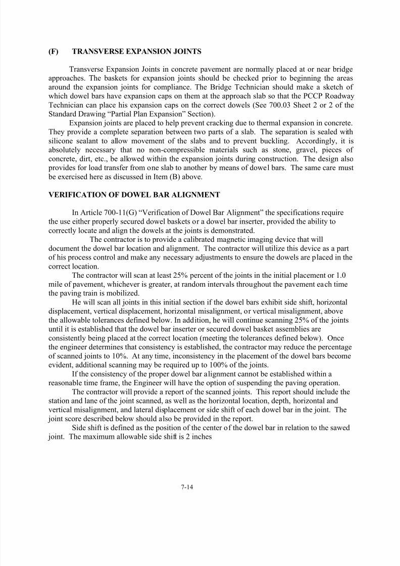
(F) TRANSVERSE EXPANSION JOINTS
Transverse Expansion Joints in concrete pavement are normally placed at or near bridgeapproaches. The baskets for expansion joints should be checked prior to beginning the areas
around the expansion joints for compliance. The Bridge Technician should make a sketch of
which dowel bars have expansion caps on them at the approach slab so that the PCCP RoadwayTechnician can place his expansion caps on the correct dowels (See 700.03 Sheet 2 or 2 of theStandard Drawing “Partial Plan Expansion” Section).
Expansion joints are placed to help prevent cracking due to thermal expansion in concrete.They provide a complete separation between two parts of a slab. The separation is sealed with
silicone sealant to allow movement of the slabs and to prevent buckling. Accordingly, it isabsolutely necessary that no non-compressible materials such as stone, gravel, pieces of
concrete, dirt, etc., be allowed within the expansion joints during construction. The design also provides for load transfer from one slab to another by means of dowel bars. The same care must
be exercised here as discussed in Item (B) above.
VERIFICATION OF DOWEL BAR ALIGNMENT
In Article 700-11(G) “Verification of Dowel Bar Alignment” the specifications requirethe use either properly secured dowel baskets or a dowel bar inserter, provided the ability to
correctly locate and align the dowels at the joints is demonstrated.The contractor is to provide a calibrated magnetic imaging device that will
document the dowel bar location and alignment. The contractor will utilize this device as a partof his process control and make any necessary adjustments to ensure the dowels are placed in the
correct location.The contractor will scan at least 25% percent of the joints in the initial placement or 1.0
mile of pavement, whichever is greater, at random intervals throughout the pavement each timethe paving train is mobilized.
He will scan all joints in this initial section if the dowel bars exhibit side shift, horizontaldisplacement, vertical displacement, horizontal misalignment, or vertical misalignment, above
the allowable tolerances defined below. In addition, he will continue scanning 25% of the jointsuntil it is established that the dowel bar inserter or secured dowel basket assemblies are
consistently being placed at the correct location (meeting the tolerances defined below). Oncethe engineer determines that consistency is established, the contractor may reduce the percentage
of scanned joints to 10%. At any time, inconsistency in the placement of the dowel bars becomeevident, additional scanning may be required up to 100% of the joints.
If the consistency of the proper dowel bar alignment cannot be established within areasonable time frame, the Engineer will have the option of suspending the paving operation.
The contractor will provide a report of the scanned joints. This report should include thestation and lane of the joint scanned, as well as the horizontal location, depth, horizontal and
vertical misalignment, and lateral displacement or side shift of each dowel bar in the joint. The
joint score described below should also be provided in the report.
Side shift is defined as the position of the center of the dowel bar in relation to the sawed joint. The maximum allowable side shift is 2 inches

8/13/2019 Construction Manual 07 Concrete Pavements 2012
http://slidepdf.com/reader/full/construction-manual-07-concrete-pavements-2012 17/45
7-15
Horizontal displacement is defined as difference in the actual dowel bar location from itstheoretical position as detailed in the standard details. The maximum allowable horizontal
displacement is 2 inches.
Vertical displacement (depth) is the difference in the actual dowel bar location from the
theoretical midpoint of the slab. The maximum allowable vertical displacement depth is 1/2inch.
Vertical Displacement
Less than ½” from mid point of the slab
Side Shiftless than 2 inches
Horizontal displacement
– less than 2 inches
Profile View
< 2 inches
< 2
d< ±1/2”
18”
12
1/2 Thickness
Plan
12

8/13/2019 Construction Manual 07 Concrete Pavements 2012
http://slidepdf.com/reader/full/construction-manual-07-concrete-pavements-2012 18/45
7-16
Dowel bar misalignment is defined as the difference in position of the dowel bar endswith respect to each other. Vertical misalignment is measured in the vertical axis whereas
horizontal misalignment is measured in the horizontal axis.
Vertical Misalignment Horizontal Misalignment
Determining a joint score for each joint scanned as below:
Joint Score = ∑(# of bars * Misalignment Category)+1
Example: A joint has 12 bars. 10 are aligned correctly. 1 bar is misaligned 16mm, and 1
bar is misaligned 22mm.
Joint Score = ∑ {(10*0) + (1 * 2) + (1 * 4)} + 1 Joint Score = 7
The joint score is a measure of combined effects of horizontal and vertical misalignment.
The joint score is determined by summing the product of the weight (shown in the table below)and the number of bars in each misalignment category and adding 1. The vertical and horizontal
dowel misalignment should be evaluated and the greater misalignment shall be utilized indetermining the joint score.
Misalignment Category, mm Weight
0 <= d <= 15 0
15< d <= 20 220< d <= 25 425 < d <= 38 5
38 <= d 10
Where d is the individual dowel bar misalignment.
A joint that has a joint score of 10 or greater will be considered locked.Identify any scanned joints where the opposing horizontal or vertical misalignment of any
two bars within the joint exceeds 1 inch. This situation will be considered a locked joint.
d d
Profile View
12
1/2 Thickness
Plan
Slab
Thickness
12

8/13/2019 Construction Manual 07 Concrete Pavements 2012
http://slidepdf.com/reader/full/construction-manual-07-concrete-pavements-2012 19/45
7-17
When a locked joint as defined above is discovered, scan the two joints immediatelyadjacent to the locked joint. If either of the adjacent joints are deemed to be locked, provide a
written proposal to address the dowel misalignment for each locked joint. No corrective actionshould be performed without written approval.
Any and all corrective action necessitated by improper joint alignment shall be at no costto the Department.
700-12 SEALING JOINTS
(A) GENERAL
All joints shall be sealed with low modulus silicone sealant. Low modulus silicone sealant
is accepted by brand name. The Materials & Tests Unit maintains a list of approved sources. AType 3 Manufacturer’s Certification is required for each lot of joint sealer shipped to a project.
The manufacturer’s recommendations and/or applicable standard drawings will detail the joint
seal configuration. It is of utmost importance that the design dimensions and shapes areachieved in the construction of the joint. Proper joint function can only be achieved by proper joint shape and by good sealant-concrete adhesion. The Engineer should schedule a meeting
with the Contractor, his personnel, and a representative from the Pavement Construction Sectionfor review of joint construction prior to beginning this phase of work.
Construction traffic may operate over joints, which have been initially sawed only. Notraffic of any type will be allowed on the pavement after the final sawing joints until the
installation of the joint sealer has been completed and the sealer is tack free. The sawing andsealing of all joints must be complete before permanent traffic is placed on the pavement.
(B) AGE OF PAVEMENT
The concrete shall be at least 14 days old before the joints are sealed. It is also required
that the surface testing, correction, and adjacent construction, including earth shoulders becomplete prior to final sawing and sealing operations.
8/13/2019 Construction Manual 07 Concrete Pavements 2012
http://slidepdf.com/reader/full/construction-manual-07-concrete-pavements-2012 20/45
7-18
(C) TEMPERATURE
The minimum air temperature is very critical to good joint and sealant performance.
Placing sealant when the temperature is less than 7 C (45 F) should not be allowed unless
approved by the State Roadway Construction Engineer.
(D) SEALING THE JOINT
The joint shall not be filled until it has been resawed, cleaned, and dried. This shall beaccomplished by sandblasting. Just prior to sealing, the joint is "blown out" with compressed air.
It is extremely important that the compressor used to supply air for cleaning joints be equippedwith traps, which will remove compressor oil and water from the air supply. Oil or water stains
on the joint wall will prevent the proper bonding of low modulus silicone sealant to the jointwall. The Technician shall specifically check to ensure the compressor is equipped with the
traps noted above.
(E) CLEANING PAVEMENT
Cleaning is best achieved by good workmanship during placement of the sealant. Refer tothe sealant manufacturer’s recommendations for curing requirements.
700-13 USE OF NEW PAVEMENT OR SHOULDER
The timely opening of Portland Cement Concrete pavement or PCCP to traffic is often
extremely important. However if traffic, especially construction traffic, is allowed on the pavement before the concrete has gained sufficient strength, the service life of the concrete
pavement may be adversely compromised. Therefore no traffic, including construction traffic, is
allowed on the completed pavement slabs until the compressive strength of the concrete hasreached 3500 psi.To determine the compressive strength of the concrete, the maturity method will be used.
To determine the compressive strength of the concrete using the maturity method, a strength-maturity relationship must be developed and verified. The procedures for developing the
maturity curve, estimating the in place concrete’s strength, and verifying the maturity curve areincluded in the Construction and Inspection of Portland Cement Concrete Pavement Manual.
Before traffic is allowed on the concrete slab, the Roadway Technician should verify anddocument that the maturity index is greater than the required Temperature-Time factor target.
This documentation should be recorded in the Technician’s Daily Report. In the absence of a strength maturity curve, traffic should not be allowed on the concrete
slab until test beams representative of the pavement have attained a compressive strength of 3500 psi.
For the placement of permanent traffic, the sawing and sealing of all joints must have been completed. Construction traffic may operate over joints which have been initially sawed
only. No traffic of any type will be allowed on the pavement after the final sawing joints until theinstallation of the joint sealer has been completed and the sealer is tack free.

8/13/2019 Construction Manual 07 Concrete Pavements 2012
http://slidepdf.com/reader/full/construction-manual-07-concrete-pavements-2012 21/45

8/13/2019 Construction Manual 07 Concrete Pavements 2012
http://slidepdf.com/reader/full/construction-manual-07-concrete-pavements-2012 22/45
7-20
The sample taken for determination of the air content should be obtained as soon as theconcrete is discharged on the road. All concrete that does not meet the Specifications must be
fully removed from the road and not incorporated into the final pavement structure.
(D) SLUMP
Refer to the Materials & Tests Minimum Sampling Guide and the Construction and
Inspection of Portland Cement Concrete Pavement Manual for the frequency and procedures for performing slump tests on concrete.
(E) COMPRESSIVE STRENGTH
Refer to the Materials & Tests Minimum Sampling Guide and the Construction and
Inspection of Portland Cement Concrete Pavement Manual for frequency and procedures for preparing and testing the compressive strength of concrete pavement test beams.
The Contractor and/or the Engineer should contact the local Materials & Tests Unit’sSection Specialist prior to beginning work to determine when field certification training and the
required examination(s) can be scheduled for all Technicians involved with the PCCPLaboratory Technician Certification.
The Engineer and the project personnel should carefully review the method and procedurefor establishing lots. This procedure is very important because it will determine the square
yardage of concrete to be affected if an adjustment in pay is necessary. There are severaldifferent items to be concerned with, such as the width of the paving operation and the type of
pavement; i.e., mainline, ramp, miscellaneous, etc. The Specifications list the criteria for eachcase and outline the procedures which are to be followed. The Pavement Construction Section of
the Construction Unit should be consulted if there are any questions on the methods and procedures for establishing lots.
The Specifications give the procedures that are to be followed in determining the “payfactors” as they apply to compressive strength. In order to standardize the procedures, the
following will apply:
1. The Engineer will determine the lot limits. This should be done to the extent possible priorto beginning paving operations.
2. Project personnel will sample the concrete and prepare 6 inches x 12 inches compressivestrength test cylinders.
3. At the completion of 28 days, project and/or lab personnel will test the compressive strengthcylinders and report the results to the Engineer.
4. The Engineer will report the test results to the Materials & Tests Unit and the PavementConstruction Section.
5. The Engineer shall calculate the pay factors for compressive strength to the nearest tenth of a
whole percent and advise the Contractor of the result of these determinations.
Whenever the compressive strength cylinders indicate concrete that fails to meet the
minimum compressive strength specified, the Engineer shall immediately notify the StateRoadway Construction Engineer.

8/13/2019 Construction Manual 07 Concrete Pavements 2012
http://slidepdf.com/reader/full/construction-manual-07-concrete-pavements-2012 23/45
7-21
(F) THICKNESS
The thickness of both concrete pavement and concrete shoulders are determined foracceptance purposes by obtaining cores from the pavement or shoulder. It is important that the
same lot determination used for compressive strength be used to determine the acceptable
thickness of the pavement.Payment will be made in accordance with Articles 710-9 or 720-9 for concrete pavementor concrete shoulders, respectively. Please refer to these Articles for specific details.
The Contractor should patch all core holes within 72 hours of taking the core using aDepartment approved non-shrink grout compatible with the pavement or shoulder concrete.
(G) SURFACE SMOOTHNESS
Article 710-7 describes in detail the surface smoothness requirements for concrete
pavements. If the concrete pavement does not meet the required surface smoothnessrequirements, the Contractor shall correct the pavement surface to the required smoothness by
the use of diamond grinding, removal and replacement or other methods approved by theEngineer.
The Contractor and/or the Engineer should contact the Pavement Construction Section prior to beginning work to determine when field certification training and the required
examination(s) can be scheduled for Technicians involved with the PCCP ProfilographTechnician Certification.

8/13/2019 Construction Manual 07 Concrete Pavements 2012
http://slidepdf.com/reader/full/construction-manual-07-concrete-pavements-2012 24/45
7-22
TECHNICIAN'S CHECKLIST
SECTION 700
CONCRETE PAVEMENTS AND SHOULDERS
General
1) Study Specifications, plans, and Special Provisions.
2) Review Contractor’s Process Control Plan. 3) Before the start of paving operations obtain slump cones, air test meters, rulers, pencils,
necessary forms, etc., which are required for the job, and make sure that all testing equipmentis in good working condition.
4) Verify that the producer’s personnel hold the necessary certifications.Batch Plant Operator (Batch Plant Certified, PCCP Certified)
Producer’s Laboratory Technician (PCCP Lab Certified) Producer’s Roadway Foreman (PCCP Roadway Certified)
5) Record in diary all conversations, observations, spot checks made, and work performed.
Plant Operation Checklist
6) Become familiar with the producer’s concrete batching and mixing equipment. 7) Verify that the Plant, Scales, etc. have been checked and approved by the Materials and Tests
Unit.8) Obtain samples of the cementious materials (cement, flyash, blast furnace slag, etc.) at the
beginning of the project and each load from a railroad car or every fourth truck tankerthereafter, to determine the origin and to assure that cement does not already contain
air-entraining agent.9) When new materials arrive, compare the material sources to the approved Concrete Mix
Design. 10) Observe the batch plant technician weigh at least one load from each lot. Verify that the
batch weights are within the acceptable tolerances.11) Check air-entraining dispenser at least once each morning and once each afternoon.
12) Check cold feed bins and piles and assure that there is no contamination or inter-mingling ofthe aggregates.
13) Verify that stockpiles are spaced or separated to prevent inter-mingling of the aggregates.Other items to check for in stockpiles are as follows:
The stockpiled area should be cleaned of vegetation, well drained, and covered with alayer of aggregate.
The material, when handled by clam bucket or conveyer belt, should not be allowed todrop free for any appreciable distance.
Avoid inclusion of foreign material when cleaning up stockpile.
Avoid use of tractor vehicles on large aggregate stockpiles.
Maintain space between stockpiles and in limited areas use bulkheads.14) Verify that no concrete remains in the trucks after dumping and is washed clean for the next
load of concrete.
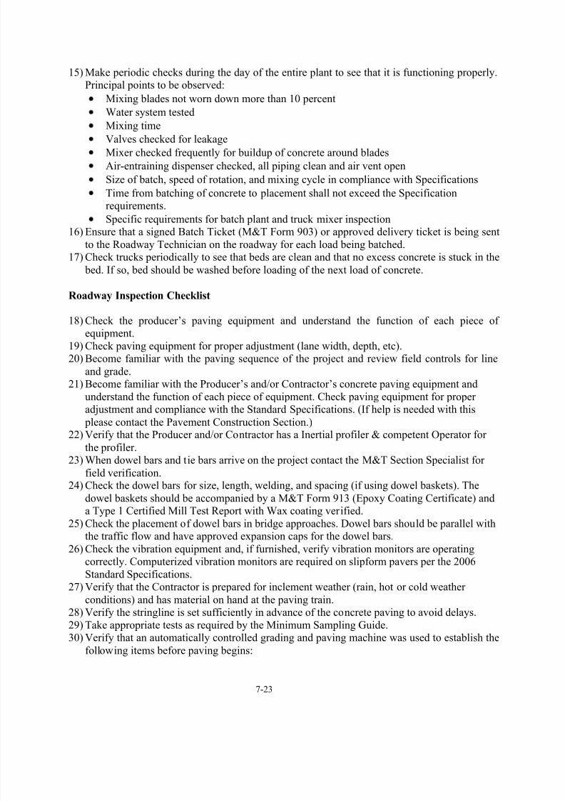
8/13/2019 Construction Manual 07 Concrete Pavements 2012
http://slidepdf.com/reader/full/construction-manual-07-concrete-pavements-2012 25/45

8/13/2019 Construction Manual 07 Concrete Pavements 2012
http://slidepdf.com/reader/full/construction-manual-07-concrete-pavements-2012 26/45

8/13/2019 Construction Manual 07 Concrete Pavements 2012
http://slidepdf.com/reader/full/construction-manual-07-concrete-pavements-2012 27/45
7-25
Verify the concrete is spreading easily without segregation giving even spreading anduniform strikeoff.
Check the Dowels, tie bars, and joint assemblies to assure that all are according to plansand Specifications. If the steel is not correct, call the M&T Section Specialist.
Verify the concrete placement operation did not dislocate the dowel bars or dowel bar
assemblies (A metal detector could be helpful).Verify the speed of the paving train equipment is matching the slowest part of the paving operation. Stopping should be minimized to alleviate bumps.
Check that the concrete pavement is maintained at a uniform consistency.
Perform slump tests and air entrainment tests at the required frequency as per theMinimum Sampling Guide, Construction and Inspection of Portland Cement Concrete
Pavement Manual, and the Engineer. Keep Plant Technician informed of any changesor problems that may arise.
Assist the Plant Technician in making test beams, if possible.34) When placing PCC pavement the roadway Technician should check spreading and vibrating
items. Some spreading and vibrating items to be checked are:
Check to see that the paver is not over or under loaded and that concrete is rolling andnot sliding in front of the screed.
Assure the use of minimum adequate vibration.
The Contractor should check vibrators at the beginning of each day’s operation. Ask theContractor to verify vibrator operation in conformity to Standard Specifications.
Check the mortar depth on surface with the index finger. If the mortar is more than 1/8inch in depth, it may be due to over vibration.
Check the concrete in front of screeds for the rolling affect (“Uniform head”). If this isnot occurring, check the air and slump and notify the Plant Technician if air or slump isout.
35) When observing PCC pavement, the roadway Technician should check the following
finishing items:
Check top of slab with a stringline and rule using uniform sized blocks set on top offorms several times daily for cross section.
Make sure hand operated 10 foot straightedges remove any discrepancies and bull floatmen remove straightedge marks.
Assure the Final surface is finished with a burlap drag according to the StandardSpecification requirements and is uniform in appearance. The Burlap drag should be
raised when not in use.
Assure transverse grooves are uniform and of correct depth and width.36) Ensure that the curing is started as soon as possible while surface is moist. Immediately after
the finishing operations have been completed and the surface water has disappeared, cure allsurfaces of the pavement as soon as possible.
Do not expose newly placed concrete pavement for more than 30 minutes before beingcovered on all exposed surfaces with curing compound. The 30 minutes may vary because of temperature and / or season.
Membrane curing compound and other curing methods should be discussed andapproved prior to use. The curing method used should be in accordance withSpecification requirements.
Ensure that the top and sides of slab are uniformly covered with curing compound, polyethylene film, or thoroughly wet burlap.

8/13/2019 Construction Manual 07 Concrete Pavements 2012
http://slidepdf.com/reader/full/construction-manual-07-concrete-pavements-2012 28/45
7-26
Ensure the correct type of membrane curing compound is being used and that it has been pretested by the Materials and Tests Unit. If the compound is not pretested, submit a
sample to the Materials and Tests Unit.
Ensure the application machine is equipped with an agitator (compressed air ormechanical) and pump.
Check for clean nozzles and uniform coverage of the slab, top and sides. Check for rateof coverage required by Standard Specifications (both mechanical and hand operatedwhen used).
37) When Observing Joint construction, study the plans, Standard Specifications, SpecialProvisions, the Construction Manual, and the Construction and Inspection of Portland
Cement Concrete Pavement Manual for all types and construct accordingly.38) The Engineer or his representative when the initial or final cuts are made or when the joints
are being filled with sealant shall observe the joint construction.39) At least 20% of all joints should be measured for depth and noted for both the initial and final
cuts.40) Joints must be thoroughly clean and dry before sealing.
41) If necessary, the Engineer may request to have a representative of the silicone sealantmanufacturer present on the project during sealing operations.
42) When paving adjacent to an existing slab, cover the transverse joint opening and crack of theexisting slab with tape or other approved material to prevent intrusion of grout into the joint
opening and crack.43) When the slip form paving method is used, all applicable checks previously discussed above
apply and in addition:
Ensure that adequate quantity of protective material is available including side forms or boards of proper dimension for temporary use.
Check the stringline or wireline for horizontal control periodically by eye.
Check trackline for grade and non-yielding surface.
Check slab thickness as recommended in Construction and Inspection of PortlandCement Concrete Pavement Manual.
Closely check on handwork necessary at the beginning and ending headers and that
proper hand vibration is being done in these areas. Make certain there is no presence ofdead concrete or excessive mortar. Make certain dowel bars, if required, are properly
placed. Check for right angles from the longitudinal joint.
Check slump frequently when in superelevation and maintain minimum slump. Themaximum edge slump is 1/4”. Use edge forms, if unable to control edge slump.
Verify that concrete is placed within the time permitted by the Standard Specifications.
Transverse joints should match from lane to lane and lane to shoulder.
Check for proper grade to match bridge approach at least 160 feet from the approach.
Marks should be made for transverse joint locations for correct sawing location on thedowel baskets. Confirm that joint locations are marked at the same location as the dowel baskets. Check dowel bar assemblies for proper placement to assure that they are
parallel with the base and centerline of the roadway and properly supported and staked.
Check the TR wires to see that they are cut.
Make sure dowel baskets are securely anchored on the bottom rail, BR wire, using thecorrect type, size, number, and length of staking pins.
Make sure that the M&T Section Specialist prior to use have checked dowel baskets andthat the baskets are wax coated.

8/13/2019 Construction Manual 07 Concrete Pavements 2012
http://slidepdf.com/reader/full/construction-manual-07-concrete-pavements-2012 29/45
7-27
Make sure that dowels are properly welded after they have been anchored (no loose bars).
Check that the base material is maintained in a dampened condition ahead of theconcrete placement.
Observe the straightedge operations and bull float operations to see that the surface is
flat and true.Make sure hand operated 10 foot straightedges remove any discrepancies and bull floatmen remove straightedge marks.
Assure the Final surface is finished with a burlap drag and is uniform in appearance. TheBurlap drag should be raised when not in use and should be used in a longitudinal
direction.
Assure transverse grooves are uniform and of correct depth and width.44) Lastly, maintain the Technician’s Daily Diary that includes hours, equipment, concrete
temperatures, air content, slump, stations paved, width, weather, air temperatures, and problems encountered. Complete the M&T Form 252 R. Retrieve the 253 L & P and attach
the 253 to the Technician’s Daily Diary.
Maturity:a) Contact the Construction Unit – Pavement Construction Section – for assistance when
doing the Maturity Method. The NCDOT test method is available by contacting the
Pavement Construction Section at 919-707-2400. b) Verify that the Contractor has approved Maturity equipment and has a Maturity curve
established in accordance with the Standard Specifications.c) The Engineer or his representative will verify 10% of all verification tests done by the
Contractor.
8/13/2019 Construction Manual 07 Concrete Pavements 2012
http://slidepdf.com/reader/full/construction-manual-07-concrete-pavements-2012 30/45
7-28
SECTION 710
CONCRETE PAVEMENT
710-1 DESCRIPTION
This section of the Specifications expands on the general requirements of Section 700 andgives the specific details and requirements for concrete pavement construction. While theseSpecifications will apply to most non-reinforced, jointed pavements with dowels, project
personnel should always refer to the plans and Project Special Provisions for exceptions to theStandard Specifications.
710-2 MATERIALS
The specifications for concrete pavement materials are detailed in Division 10 of the
Standard Specifications.
710-3 COMPOSITION OF CONCRETE
Concrete pavement mixes are designed by the Contractor and submitted through theEngineer to the Materials & Tests Unit for review and approval. Section 1000-3 of the Standard
Specifications details the various requirements for these mixes and the supporting data that theContractor must supply.
The Strength-Maturity curve should also be submitted with the Concrete Mix Design andthe other required information (See 700-13 in the Standard Specifications).
Prior to submitting a proposed mix to the Materials & Tests Unit, the Engineer shouldsatisfy himself that all of the information required for evaluating the mix has been furnished. On
most concrete paving projects, more than one mix will be required due to the use of hand- placement methods, early strength requirements, or other factors. The Engineer should be
thoroughly familiar with the requirements of the project and have readily available anyinformation required relating to job mixes.
The Engineer and the Contractor should pay close attention to those quarries whoseaggregates are known to exhibit ASR characteristics. These quarries are listed on the Materials
and Tests Unit’s website. When a concrete mix design contains aggregates from one of theselisted quarries, the design should also include a pozzolan, such as fly ash, GGBFS, or Microsilica
in the amounts listed in Article 1024-1, to inhibit the potential ASR problems.The adjustment of mix designs when necessitated by low compressive strength is a critical
factor, and the Engineer should notify the State Construction Engineer and Contractorimmediately upon failure of the initial test beams to meet Specification requirements. The
failure of a series of test cylinders to meet Specification compressive strength requirements atany time during production may indicate faulty testing procedures or a change in materials, and
immediate checks and tests to determine the source of the deficiency should be made.
710-4 ACCEPTANCE OF CONCRETE
Acceptance testing and sampling of the concrete mix is the responsibility of the Engineer.The Contractor is required to furnish the materials to be sampled and tested. The Specifications
outline several areas where the Engineer will perform acceptance testing.

8/13/2019 Construction Manual 07 Concrete Pavements 2012
http://slidepdf.com/reader/full/construction-manual-07-concrete-pavements-2012 31/45
7-29
Assistance in determining the correct procedures and frequency of testing can be found bycontacting the Materials & Tests Unit or by contacting the Pavement Construction Section of the
Construction Unit. Also refer to Article 700-15 for more details on compressive and flexuralstrength sampling and testing requirements.
When the average of the Department’s compressive strength test results are below 4500
psi, the Engineer will perform an investigation..
710-5 CONSTRUCTION METHODS
Concrete pavement will be constructed in accordance with the provisions of Section 700.
Concrete pavement should be placed in 2-lane minimum widths; however, there are a fewexceptions noted. Refer to the plan details for joint locations and spacing, lane widths, etc.,
when large areas of concrete pavement are to be constructed, such as parking lots, in rest areas,weigh stations, etc.
710-6 FINISHING
The concrete in front of finisher float machine screeds should be rolling, not sliding. (If
not rolling, check to ensure that air-entrainment and slump meet specifications.) The first screedon the first pass should carry a uniform roll of concrete 6 to 8 inches in diameter and leave the
concrete surface slightly high. The second screed on the first pass should carry a uniform roll ofconcrete 3 to 4 inches in diameter and cut the concrete to slightly above the level of the top of
form. The forward screed should be tilted slightly to provide compaction and surge. Increasingthe speed of transverse motion in relation to the forward motion usually eliminates tearing.
Spreader and screeds shall operate continuously over the joints without disruption or lifting ofthe screed. For a good finish without bumps the paver should move continuously throughout the
days operation with little or no stopping.Experience has shown that supplemental finishing will be required for the concrete
pavement to meet rideability requirements. This supplemental finishing may be accomplishedeither by an automated float attached to the paver or a tube machine. Except in areas not readily
assessable to pavers and finishing machines, the use of straight edges for finishing operationsshall be held to the minimum necessary. Proper finishing is the necessary step in the paving
process in order to obtain the desired ride quality. The Technician should observe theContractor’s finishing methods and techniques so that he may be in a better position to insist on
appropriate corrective action if the final surface testing described later in this section of theManual indicates a need to do so.
The use of excessive water during the finishing operations will not be permitted as thismay cause the top surface of the concrete to have a weaker strength and potentially scale or spall
of f early in the pavement’s service life. It is the Contractor’s responsibility and the Department’s objective to produce a quality
pavement surface that will give a favorable ride without the use of grinding. Project personnel
must insist that this objective be carried out by the Contractor even if it means stopping the
paving operation until the problem can be corrected. When necessary, the Engineer shouldnotify both the Division Engineer and the State Construction Engineer. The Contractor should
not be allowed to continue paving when poor rideability is being achieved or excessive grindingis being required.
The final operation to obtain the desired surface texture is that of grooving the surface.This involves the movement of steel tines transversely across the pavement surface while it is

8/13/2019 Construction Manual 07 Concrete Pavements 2012
http://slidepdf.com/reader/full/construction-manual-07-concrete-pavements-2012 32/45
7-30
still in a plastic state in order to scratch small grooves in the pavement surface. This willimprove the skid resistance of the pavement and reduce the hydroplaning affect to vehicles in
inclement weather by providing channels for the surface water to run off the pavement surfacetoward the shoulders. The PCCP Roadway Technician should monitor this tining operation to
ensure that the Contractor’s timing for performing the transverse grooving is appropriate to
achieve the desired results. If the Contractor is attempting to tine the pavement too early, thesteel tines will have a tendency to drag some aggregate out of the surface, or the depth of thetines will be greater than the required depth. Conversely, if the tining is done too late, the
grooves may not be deep enough and grinding of the pavement will be required to provideenough skid resistance. In addition, checks should be made to prevent the overlapping of
adjacent grooving and to minimize the blank areas between passes. The Technician should referto the plans and/or standard drawings for specific details on tine dimensions, location relative to
edge of pavement, etc.The Contractor will provide a textured surface with an average texture depth of 0.8 mm as
tested in accordance with ASTM E 965 (Test Method for Measuring Pavement Macrotexture Depth Using a Sand Volumetric Technique) with no single test having a texture depth of 0.5 mm
or less.The Contractor will perform four randomly located tests in accordance with ASTM E 965
within the initial pavement lot of each mobilization and provide test results to the Engineer. Alot is defined in Article 710-4. If the average of the four tests does not meet the above criteria,
make appropriate changes to the surface texture operations and test the next lot as detailed above.Once the surface texture process is established to meet minimum texture requirements, maintain
consistency within the operation to provide the above minimum texture depth. Performadditional sand patch tests in accordance with ASTM E 965 when directed.
Should the surface texture become damaged or reduced by rain, grinding or any otheraction, reestablish or restore surface texture by an approved method.
Once the pavement has hardened, checks of the tining depth can be made to determinecompliance with Article 710-6 describes the procedure required to check the depth of the texture.
The depth of the texture is important. The grooves are constructed to break the plainsurface and thereby prevent hydroplaning. But, the grooves can create a noise problem.
In order to minimize the noise from the pavement surface, the tine depths shall be asshallow as possible within the specifications. This will insure safety but minimize any
objectionable noise.The apparatus needed to perform ASTM E 965, “Test Method for Measuring Pavement
Macrotexture Depth Using a Sand Volumetric Technique” is as follows:

8/13/2019 Construction Manual 07 Concrete Pavements 2012
http://slidepdf.com/reader/full/construction-manual-07-concrete-pavements-2012 33/45
7-31
Container for Glass Spheres
Sample cylinder (35mm film container)
Ruler
Spreading Tool (Hockey Puck)
Surface Cleaning Brushes (Wire Brush, Soft Bristle Brush)
Small Straightedge (small spatula)
Portable Wind Screen
Procedure:
Begin by selecting four randomly selected test areas in each lot (same stations as strength, andthickness cores). Note: The same technician should perform all the testing.
1. Inspect the test area to be measured. Test area must be a dry homogeneous areathat contains no unique, localized features such as cracks or joints.
2. Thoroughly clean the surface with the stiff wire brush to remove any residue andthen with the soft bristle brush remove any of the residue, debris, or loosely
bonded aggregate particles from the test surface.3. Position the portable wind screen around the test area.
4. Fill the small sample cylinder of known volume with the glass spheres and gentlytap the base of the cylinder several times on a rigid surface. Add more material to
fill the cylinder to the top and level with a straightedge. If a set of laboratoryscales are available, determine the mass of material in the cylinder and use this
mass of material sample for each measurement.5. Pour the measured volume or weight of material onto the cleaned test surface
within the area protected by the portable wind screen.6. Carefully spread the glass spheres into a circular patch with the spreading tool
(hockey puck), rubber side down, filling the surface voids flush with the
aggregate particle tips.7. Measure and record the diameter of the circular area covered by the glass spheres
at a minimum of four equally spaced locations, such as 0°- 180°, 45° - 225°, 90° -270°, 135° - 315°, around the circumference.
8. Compute and record the average diameter of the circle.

8/13/2019 Construction Manual 07 Concrete Pavements 2012
http://slidepdf.com/reader/full/construction-manual-07-concrete-pavements-2012 34/45
7-32
Calculation:
Cylinder Volume:
o Calculate the internal volume of the sample container as follows:∏d
2h
V= 4
Where:V = internal cylinder volume, in3, (mm
3)
d = internal cylinder diameter, in. (mm), and
h = cylinder height, in. (mm).
MATXd or Average Macro Texture Deptho Calculate the average macro texture depth as follows:
4V
MATXd= ∏D2
Where:
MATXd = Mean texture depth of pavement macrotexture, in. (mm).V = sample volume, in3, (mm
3), and
D = average diameter of the test area covered by the glass spheres, in.
(mm).An example of one test area location for calculating the mean texture depth of the
pavement macrotexture is below:
Volume of glass spheres, V:__________ mm3
Dia. 1: _____ mm Dia. 2 _____ mm Dia. 3: _____ mm Dia. 4: _____ mm
Average Diameter, Davg: mm
Avg. Macro Texture Depth MATX4 _____ mm
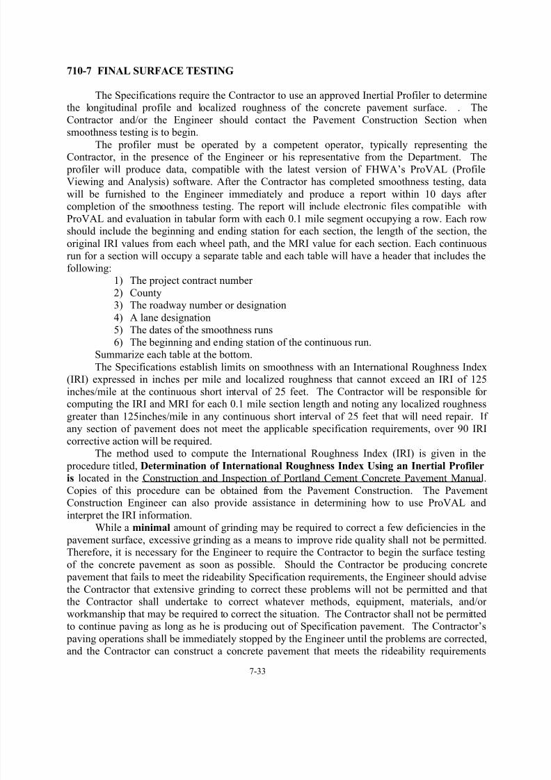
8/13/2019 Construction Manual 07 Concrete Pavements 2012
http://slidepdf.com/reader/full/construction-manual-07-concrete-pavements-2012 35/45
7-33
710-7 FINAL SURFACE TESTING
The Specifications require the Contractor to use an approved Inertial Profiler to determinethe longitudinal profile and localized roughness of the concrete pavement surface. . The
Contractor and/or the Engineer should contact the Pavement Construction Section when
smoothness testing is to begin.The profiler must be operated by a competent operator, typically representing theContractor, in the presence of the Engineer or his representative from the Department. The
profiler will produce data, compatible with the latest version of FHWA’s ProVAL (ProfileViewing and Analysis) software. After the Contractor has completed smoothness testing, data
will be furnished to the Engineer immediately and produce a report within 10 days aftercompletion of the smoothness testing. The report will include electronic files compatible with
ProVAL and evaluation in tabular form with each 0.1 mile segment occupying a row. Each rowshould include the beginning and ending station for each section, the length of the section, the
original IRI values from each wheel path, and the MRI value for each section. Each continuousrun for a section will occupy a separate table and each table will have a header that includes the
following: 1) The project contract number
2) County3) The roadway number or designation
4) A lane designation5) The dates of the smoothness runs
6) The beginning and ending station of the continuous run.Summarize each table at the bottom.
The Specifications establish limits on smoothness with an International Roughness Index(IRI) expressed in inches per mile and localized roughness that cannot exceed an IRI of 125
inches/mile at the continuous short interval of 25 feet. The Contractor will be responsible forcomputing the IRI and MRI for each 0.1 mile section length and noting any localized roughness
greater than 125inches/mile in any continuous short interval of 25 feet that will need repair. Ifany section of pavement does not meet the applicable specification requirements, over 90 IRI
corrective action will be required.The method used to compute the International Roughness Index (IRI) is given in the
procedure titled, Determination of International Roughness Index Using an Inertial Profiler
is located in the Construction and Inspection of Portland Cement Concrete Pavement Manual.
Copies of this procedure can be obtained from the Pavement Construction. The PavementConstruction Engineer can also provide assistance in determining how to use ProVAL and
interpret the IRI information.While a minimal amount of grinding may be required to correct a few deficiencies in the
pavement surface, excessive grinding as a means to improve ride quality shall not be permitted.Therefore, it is necessary for the Engineer to require the Contractor to begin the surface testing
of the concrete pavement as soon as possible. Should the Contractor be producing concrete
pavement that fails to meet the rideability Specification requirements, the Engineer should advise
the Contractor that extensive grinding to correct these problems will not be permitted and thatthe Contractor shall undertake to correct whatever methods, equipment, materials, and/or
workmanship that may be required to correct the situation. The Contractor shall not be permittedto continue paving as long as he is producing out of Specification pavement. The Contractor’s
paving operations shall be immediately stopped by the Engineer until the problems are corrected,and the Contractor can construct a concrete pavement that meets the rideability requirements

8/13/2019 Construction Manual 07 Concrete Pavements 2012
http://slidepdf.com/reader/full/construction-manual-07-concrete-pavements-2012 36/45
7-34
with minimal or no grinding. The Construction Unit shall be apprised of the need to suspend theContractor’s operations in order to gain compliance with the rideability requirements.
The payment for surface testing is full compensation for the Contractor furnishing,maintaining, and operating the profiler and any necessary equipment. Also included in the unit
price are graph paper and any other materials or supplies that are necessary to satisfactorily
complete the surface testing.
710-8 PAVEMENT MARKING
The Contractor must press metal dies having beveled faces into the fresh concrete along
the outside shoulder to mark the stations of the project. The Stations should be marked inaccordance with the plans and Standard Drawing No. 710.01. In addition to the station
markings, the location of all shoulder drain outlets and underground utility crossings shall bemarked on the pavement edge nearest the outlet. The location of the shoulder drain outlet or
drainage structure containing the drainage outlet should be marked perpendicular.
710-9 THICKNESS TOLERANCES
The determination of pavement thickness for acceptance is determined by themeasurement of cores tested in accordance with AASHTO T 148 as modified by the Department.
The Engineer will select and locate the random locations for core samples. The Contractor shallcore the selected locations in the presence of the Engineer. The Engineer shall deliver the
samples to the Materials & Tests Unit, which will measure the samples and report the results.The thickness measurements are reported to the State Roadway Construction Engineer
who makes the final determination under the provisions of Article l05-3 of the StandardSpecifications as to any reduction in payment that may be necessary for deficient pavement
thickness.This article also provides the allowable tolerance for pavement thickness and the sanctions
for deficient depth. Payment shall be made based on the thickness reported in accordance withArticle 710-11.
710-10 MEASUREMENT AND PAYMENT
(A) GENERAL
This article describes the method of measurement of concrete pavement. Separatemeasurement will be made for pavement lots, which are deficient in either thickness orcompressive strength or both. This article also covers payment of Surface Testing Concrete
Pavement.
(B) PAVEMENT DEFICIENT IN THICKNESS
This article covers details of the method of payment for lots deficient in the thickness ofPortland Cement Concrete pavement. Pay factors are covered from 0.2” to 1.00” and if pavement
is deficient by more than 1.0”.

8/13/2019 Construction Manual 07 Concrete Pavements 2012
http://slidepdf.com/reader/full/construction-manual-07-concrete-pavements-2012 37/45
7-35
(C) CONCRETE PAVEMENT VARYING IN STRENGTH
This article covers details of the method of payment for lots deficient in compressive andflexural strength of Portland Cement Concrete pavement.
1. The pay factor for pavement achieving a compressive strength in 28 days of 4500 psi or greater is 100%. The pay factor for pavement achieving compressive
strengths ranging from 4500 psi to 3000 psi is calculated using the formula below.
PAY FACTOR % = 100.0 – [0.05 x (4,500 – Compressive Strength)](pay factor is rounded to the nearest tenth of one percent)
2. The pay factor for pavement achieving a flexural strength in 28 days of 650 psi orgreater is 100%. The pay factor for pavement achieving flexural strengths ranging
from 650 psi to 600 psi at 28 days is calculated using the formula below.
PAY FACTOR % = 100.0 – (650 psi – PSI)(pay factor is rounded to the nearest tenth of one percent)
(B) MULTIPLE ADJUSTMENTS IN PRICE
This article covers pavement lots found to be deficient in both thickness and strength.
TECHNICIAN'S CHECKLIST
SECTION 710
CONCRETE PAVEMENTS AND SHOULDERS
1) Ensure texturing is properly performed at the appropriate time.
2) Check that the texture marks are uniform and parallel to the centerline.3) Verify texture by texture testing and observing the Contractor’s operations.
4) Check that the tines have proper random spacing, width, and are applied at the properdepth.
5) Determine the locations of thickness cores using random numbers.6) Observe the Contractor’s coring operations to verify authenticity.
7) The Contractor furnishes all necessary equipment – Inertial profiler - and supplies forfinal surface testing. The Contractor operates the profiler with a competent operator and
conducts test in presence of the Engineer within 7 days after receiving authorization to perform testing. .
8) Observe calibrations of profiler at the beginning of each day's operation to ensure thatvertical deviations and horizontal distances are being recorded accurately.
9) Retrieve raw data from the Contractor immediately after surface testing is complete on anapproved media. Data should be compatible with the latest version of ProVAL.
10) Verify the Contractor’s International Roughness Index (IRI) by using the latest version ofProVAL and note all localized roughness as described in the Construction and Inspection
of Portland Cement Concrete Pavement Manual.11) Immediately notify the Engineer when the requirements for final surface testing are not
met.12) Verify the Station marking and shoulder drain outlet locations are stamped in the
pavement according to plans and Specifications.

8/13/2019 Construction Manual 07 Concrete Pavements 2012
http://slidepdf.com/reader/full/construction-manual-07-concrete-pavements-2012 38/45
7-36
SECTION 720
CONCRETE SHOULDERS
720-1 DESCRIPTION
This section of the Specifications addresses the construction of concrete shoulders.Concrete shoulders are constructed in accordance with the general requirements of Section 700and the specific requirements included in this section.
720-2 MATERIALS
Concrete shoulders are constructed of the same quality concrete as required in the concrete
pavement. The material requirements are detailed in Division 10 of the Standard Specifications.
720-3 COMPOSITION OF CONCRETE
Refer to Article 710-3 of this Manual and Section 1000-3 of the Specifications for details.
720-4 ACCEPTANCE OF CONCRETE
Acceptance sampling and testing of the concrete mix for shoulders is the responsibility of
the Engineer. The Contractor is required to provide process control and to furnish the materialsto be sampled and tested. The Engineer will determine the extent of each lot for compressive
strength and thickness testing.Assistance in determining the correct procedures and frequency of testing can be obtained
by contacting the Materials & Tests Unit or by contacting the Pavement Construction Section ofthe Construction Unit.
720-5 EQUIPMENT
Equipment used in the construction of the concrete shoulders shall meet the requirements
of Sections 700 and 1000 of the Standard Specifications. Where slipform pavers are used to place the concrete shoulder, they shall operate on fixed continuous reference lines for both
horizontal and vertical control, except when approved by the Engineer. The previously placedmainline concrete pavement surface may be used in conjunction with a mobile ski/stringline
device. The Specifications do allow for the waiver of this requirement; however, the StateRoadway Construction Engineer should be consulted prior to approving such a request.
720-6 CONSTRUCTION METHODS
The concrete shoulder will normally be supported by both the exposed portion of the base
and the earth shoulder. It is, therefore, extremely important that specification density beachieved in the earth portion of the paving platform such that stresses caused by settlement of the
shoulder are not induced into the concrete shoulder. The end result of such stresses may beextensive cracking of the shoulder concrete. Also, the Technician should be mindful of the fact
that the base and the adjoining concrete pavement edge need to be clean before placing theshoulder concrete.

8/13/2019 Construction Manual 07 Concrete Pavements 2012
http://slidepdf.com/reader/full/construction-manual-07-concrete-pavements-2012 39/45
7-37
The spreading and finishing of the mix is similar to that of concrete pavementconstruction. The shoulder typical sections should be frequently reviewed and adjustments made
to the equipment where required, such that the desired slope, cross-sectional shape, andminimum thickness of the shoulder is achieved.
Use a curing period of three curing days for straight cement mix designs and seven curing
days for pozzolan mix designs. A curing day is any consecutive 24-hour period beginning withthe mixing of the concrete when the air temperature next to the shoulder does not fall below40°F. During cool periods, a hi-low thermometer and maturity meters should be used to keep a
daily check on the temperature beneath the protective covering and near the corners of the PCC pavement. These readings shall be recorded in the project diary. No traffic, construction or
otherwise - except for the purpose of sawing joints will be allowed on the shoulder until thecompletion of the curing period.
720-7 FINISHING
Finishing of concrete shoulders is similar to that of concrete pavement, except that the
final finish is accomplished by burlap dragging or brooming rather than with metal tines.
720-8 JOINTS
The Specifications require that joints in the concrete shoulder match the joints of theconcrete pavement. Dowels are typically not required on the transverse joints in the concrete
shoulders unless otherwise specified in the plans. Refer to Articles 700-11 and 700-12 of thisManual for joint construction and sealing requirements.
720-9 THICKNESS TOLERANCES
The Engineer will determine the random locations of core samples for the determination
of shoulder pavement thickness. The Contractor shall core the selected locations in the presenceof the Technician. The Engineer will deliver the samples to the Materials & Tests Unit, which
will measure the samples and report the results. The State Construction Engineer will make, inaccordance with the provisions of Article 105-3, the final determination as to shoulder depth
acceptability, and will also determine appropriate pay factors where necessary. The Engineershould be prepared to assist the Materials & Tests Unit in determining the theoretical shoulder
thickness at each core location. The Materials & Tests Unit shall make the comparison betweenthe actual and theoretical thickness and will compute the average deviation for the project. Upon
receipt of this final determination, test results and pay factors from the Construction Unit, theEngineer shall notify the Contractor of the results.
720-10 MEASUREMENT AND PAYMENT
This article describes the method of measurement of concrete shoulders. Separate
measurement will be made for pavement lots, which are deficient in either thickness orcompressive strength or both.
This article also describes in detail the basis of payment for various concrete shoulderitems. Also included are the procedures for computing and applying price adjustments for
pavement deficient in thickness, pavement compressive strength variability and deficiency, andfor multiple deficiencies.

8/13/2019 Construction Manual 07 Concrete Pavements 2012
http://slidepdf.com/reader/full/construction-manual-07-concrete-pavements-2012 40/45
7-38
SECTION 725
FIELD LABORATORY FOR
PORTLAND CEMENT CONCRETE PAVEMENT
725-1 DESCRIPTION
The provisions of this section of the Specifications are explicit and the Engineer shouldensure that, within reason, all of the requirements are met. Judgment may be applied, but the
intent of this section is that the Contractor shall provide an adequate facility and receive rentalfor its use. Payment for the field laboratory represents full compensation for the Contractor's
furnishing a curing shelter or lime-water tank at his discretion.
725-2 GENERAL REQUIREMENTS
This section describes in detail the requirements for the field laboratory. The Engineershould contact the Materials & Tests Unit and/or the Pavement Construction Section for
assistance in approving the laboratory and equipment, if needed.
725-3 COMPENSATION
This article describes the method to be used in making partial payments and final paymentfor the Field Lab Rental.
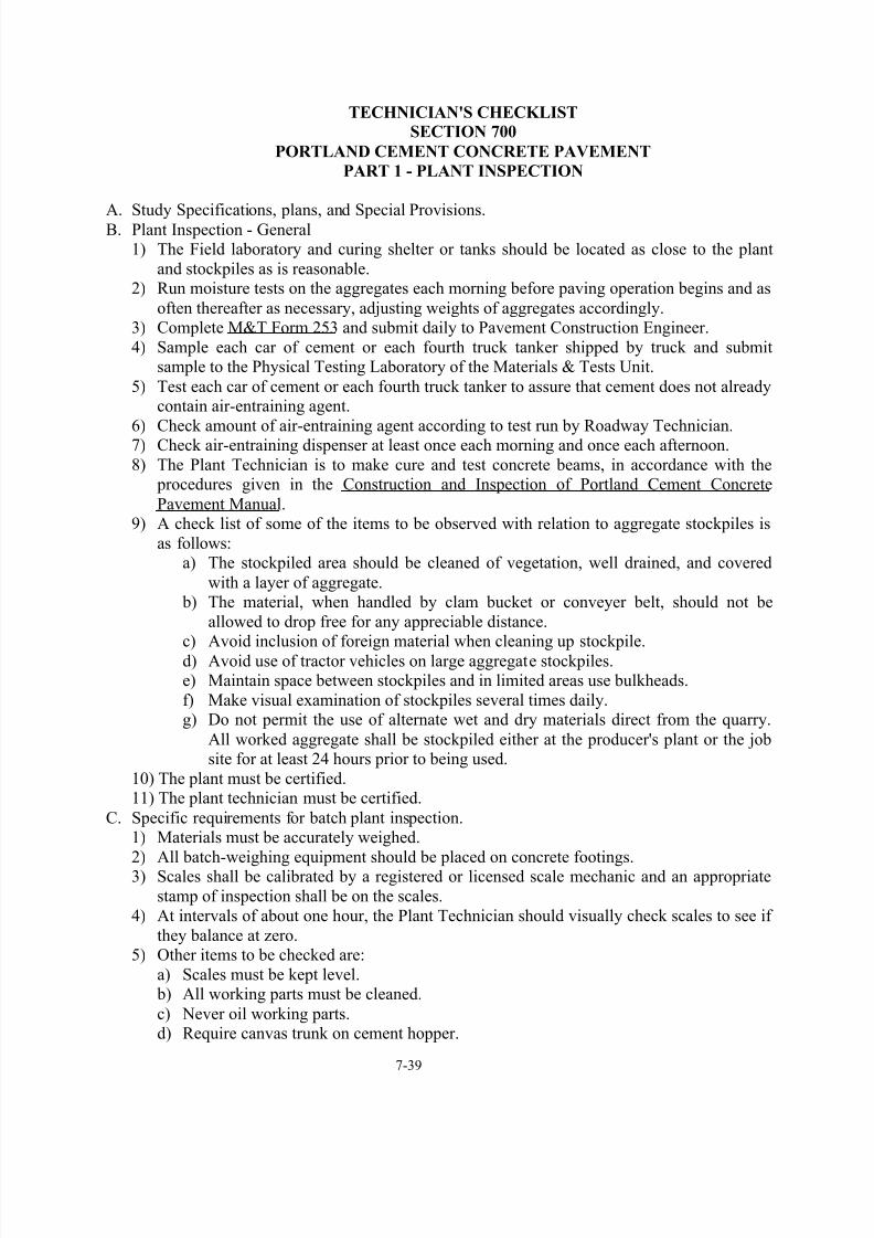
8/13/2019 Construction Manual 07 Concrete Pavements 2012
http://slidepdf.com/reader/full/construction-manual-07-concrete-pavements-2012 41/45

8/13/2019 Construction Manual 07 Concrete Pavements 2012
http://slidepdf.com/reader/full/construction-manual-07-concrete-pavements-2012 42/45
7-40
6) All batch trucks must be checked for compliance to Specifications before being permitted on the project.
D. Specific requirements for central mixed plant inspection.1) Principal points to be observed:
a) Mixing blades not worn down more than 10 percent
b)
Water system testedc) Mixing timed) Valves checked for leakage
e) Mixer checked frequently for buildup of concrete around bladesf) Air-entraining dispenser checked, all piping clean and air vent open
g) Size of batch, speed of rotation, and mixing cycle in compliance with Specifications2) Time from batching of concrete to placement shall not exceed the Specification
requirements.E. Specific requirements for batch plant and truck mixer inspection.
1) Refer to Division 10 of the Specifications.

8/13/2019 Construction Manual 07 Concrete Pavements 2012
http://slidepdf.com/reader/full/construction-manual-07-concrete-pavements-2012 43/45

8/13/2019 Construction Manual 07 Concrete Pavements 2012
http://slidepdf.com/reader/full/construction-manual-07-concrete-pavements-2012 44/45
7-42
6) Dowels, tie bars, joint assemblies all according to plans and Specifications.7) The Contractor should be reminded that all equipment speeds must be adjusted to match
the slowest operation.8) Perform slump tests and air entrainment tests at the required frequency. Keep Plant
Technician informed.
9) Assist Roadway Technician in making test cylinders and if necessary, assist LaboratoryTechnicians with making test beams.10) Station marking and shoulder drain outlet locations placed according to plans and
Specifications.11) Protection from cold weather and rain as required by Specifications adhered to by
Contractor.F. Spreading and Vibrating:
1) Use minimum adequate vibration.2) Vibrators checked by the Pavement Construction Engineer's representative before use
and as necessary by observation for conformity to Specifications.3) Check electronic vibration monitoring device several times daily. Contractor to provide
reports as per the Standard Specifications (Article 700-6)4) Check mortar depth on surface with index finger. If more than 3 mm (1/8 inch) may be
due to over vibration.5) Concrete in front of screeds rolling (if not, check air and slump).
6) Screeds carrying uniform roll.7) Forward screed tilted slightly to provide compaction and surge.
G. Finishing:1) Check top of slab with string line and rule using uniform sized blocks set on top of forms
several times daily for cross section.2) Make sure hand operated 3 meter (10 foot) straightedges remove any discrepancies and
bull float men remove straightedge marks.3) Slab edged along forms to proper radius.
4) Final surface finish with burlap drag according to Specification requirements anduniform. Burlap drag raised when not in use.
5) Assure transverse grooves are uniform and of correct depth and width.H. Final Surface Testing:
1) Contractor furnishes an approved inertial profiler and competent profiler operator.2) Contractor furnishes all necessary equipment and supplies and conducts test in presence
of the Engineer or his representative no later than 7 days after receiving authorization tostart smoothness testing.
3) Observe the calibration of profiler at the beginning each day's operation (as a minimum)to ensure that vertical deviations and horizontal distances are being recorded accurately.
4) If specification requirements for rideability are not met, the Technician shall immediatelynotify his Engineer who may contact the Construction Unit for further guidance.
5) Retrieve raw data from the operator immediately after smoothness testing is completed
for a day’s run. The operator should supply all data on approved media (CD-R, DVD-R,
or “flash drive”) which will not be returned.6) Engineer computes the International Roughness Index (IRI) to verify Contractor’s results
and notes all bumps that exceed the localized roughness part of the specifications.7) Contractor will submit documentation and electronic data of the evaluation of each
section within 10 days after completion of the smoothness testing per the StandardSpecifications.
8/13/2019 Construction Manual 07 Concrete Pavements 2012
http://slidepdf.com/reader/full/construction-manual-07-concrete-pavements-2012 45/45
I. Curing:
1) Started as soon as possible while surface is moist.2) Top and sides of slab uniformly covered.
3) Membrane curing compound:
a)
Correct type and pretested or submit sample b) Application machine to be equipped with agitator (compressed air or mechanical) and pump.
c) Check for clean nozzles and uniform coverage. Check for rate of coverage required by Specifications (both mechanical and hand operated when used).
4) Other curing methods should be discussed and approved prior to use and then one inaccordance with Specification requirements.
J. Joints:1) Study plans, Specifications, standard plans, Special Provisions, and the Construction
Manual for all types and construct accordingly.2) Must be clean and dry before sealing.
3)
Sealed in accordance with Specifications. Sealing equipment operated in accordancewith manufacturer's recommendations.
K. Slip form paver method:L. When this method is used, all applicable checks previously listed apply and in addition:
1) Become familiar with equipment to be used.2) Ensure that adequate quantity of protective material is available including side forms or
boards of proper dimension for temporary use.3) Check wire line for horizontal control periodically by eye.
4) Check track line for grade and non-yielding surface.5) Check slab thickness as recommended in Manual.
6) Close check on handwork necessary at beginning and ending headers and proper handvibration.
7) Check slump frequently when in superelevation and maintain minimum slump. Use edgeforms if unable to control edge slump.
8) Observe carefully the making of the header when paving is stopped. Make certain thereis no presence of dead concrete or excessive mortar. Check adequacy of hand vibration
adjacent to the header. Make certain dowel bars, if required, are properly placed.