Construction and operation experience of digitalized Safety Systems of Japanese ABWR 20-22 May 2009...
40
Construction and operation experience of digitalized Safety Systems of Japanese ABWR 20-22 May 2009 Takaki Mishima Tokyo Electric Power Company Legal Notice: This documentation contains technical knowledge and secret information that belong to TEPCO. Therefore, it shall not be disclosed to third parties without consent of TEPCO. 22 nd Meeting the IAEA TWG-NPPIC
-
Upload
lambert-weaver -
Category
Documents
-
view
223 -
download
2
Transcript of Construction and operation experience of digitalized Safety Systems of Japanese ABWR 20-22 May 2009...
Construction and operation experience of digitalized Safety Systems of Japanese ABWR
20-22 May 2009
Takaki Mishima
Tokyo Electric Power Company
Legal Notice:This documentation contains technicalknowledge and secret information thatbelong to TEPCO. Therefore, it shall not be disclosed to third parties without consent of TEPCO.
22nd Meeting the IAEA TWG-NPPIC
2
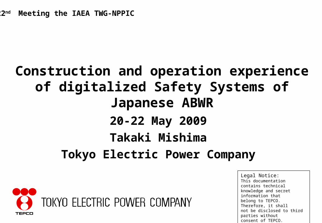
•Nuclear Power Generation in Japan
• I&C development history of TEPCO’s BWRs
• I&C development of Kasiwazaki-Kariwa Unit No.6/7
• Construction and operation experience of digitalized Safety Systems for Kasiwazaki-Kariwa Unit No.6/7
• Conclusion• Recommendations to IAEA TWG
CONTENTS
3
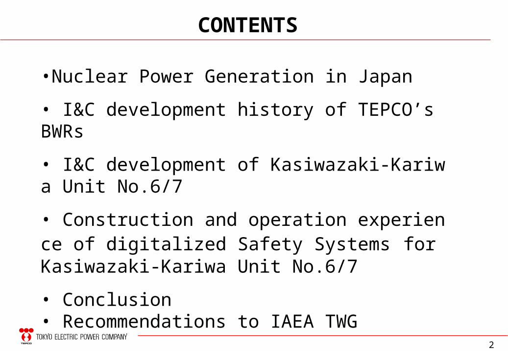
• 55 units of commercial NPP in operation
49.6 GWe capacity in total / 30% of Japanese power supply
→ PWR: 23 units, BWR: 28 units , ABWR: 4 units
• 3 units (ABWR: 2 units, PWR: 1 unit) under construction and 1 unit (Tokai) in decommissioning stage
• 3 units (ABWR: 1 unit, APWR: 2 units) under review by NISA
• 7 units under planning
• 1 prototype FBR unit (Monju) in pre-operational phase and 1 ATR unit (Fugen) in decommissioning stage
Nuclear Power Generation in Japan (1/2)
4
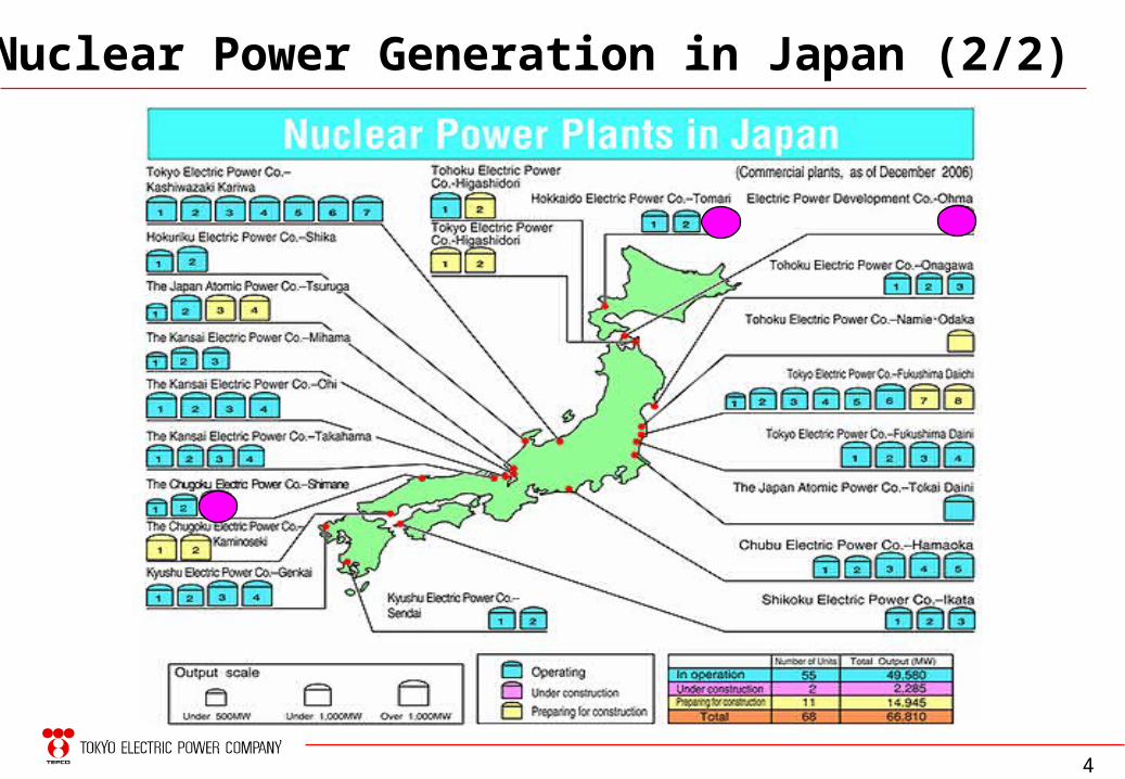
Nuclear Power Generation in Japan (2/2)

17 BWR units with a total installed capacity of 17.3 GWe (35% of Japanese nuclear power)
Kashiwazaki Kariwa NPS (KK)
July 19971356ABWR7
Nov. 19961356ABWR6
April 19901100BWR55
Aug. 19941100BWR54
Aug. 19931100BWR53
Sep, 19901100BWR52
Sep. 19851100BWR51
OperationOutput (MWe)TypeUnit
1385ABWR(2)
1385ABWR(1)
OperationOutput (MWe)TypeUnit
Higashidori NPS
1380ABWR(8)
1380ABWR(7)
Oct. 19791100BWR56
April 1978784BWR45
Oct. 1978784BWR44
Mar. 1976784BWR43
July 1974784BWR42
Mar, 1971460BWR31
OperationOutput (MWe)TypeUnit
Aug. 19871100BWR54
June 19851100BWR53
Feb. 19841100BWR52
April 19821100BWR51
OperationOutput (MWe)TypeUnit
Fukushima Daini NPS (2F)
Fukushima Daiichi NPS (1F)
TEPCO Nuclear Fleet
6
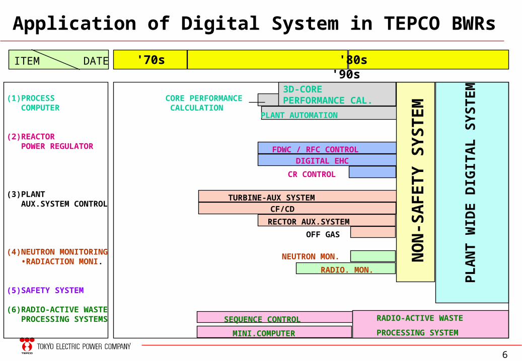
Application of Digital System in TEPCO BWRs
(1)PROCESS COMPUTER
(2)REACTOR POWER REGULATOR
(3)PLANT AUX.SYSTEM CONTROL
(4)NEUTRON MONITORING •RADIACTION MONI.
(5)SAFETY SYSTEM
(6)RADIO-ACTIVE WASTE PROCESSING SYSTEMS
ITEM DATE '70s '80s '90s
CORE PERFORMANCE CALCULATION
3D-CORE PERFORMANCE CAL.
PLANT AUTOMATION
FDWC / RFC CONTROL
CR CONTROL
TURBINE-AUX SYSTEM
DIGITAL EHC
CF/CD
OFF GAS
NO
N-S
AF
ET
Y S
YS
TE
M
RECTOR AUX.SYSTEM
NEUTRON MON.
RADIO. MON.
SEQUENCE CONTROL RADIO-ACTIVE WASTE
PROCESSING SYSTEMMINI.COMPUTER
PL
AN
T W
IDE
DIG
ITA
L S
YS
TE
M
7
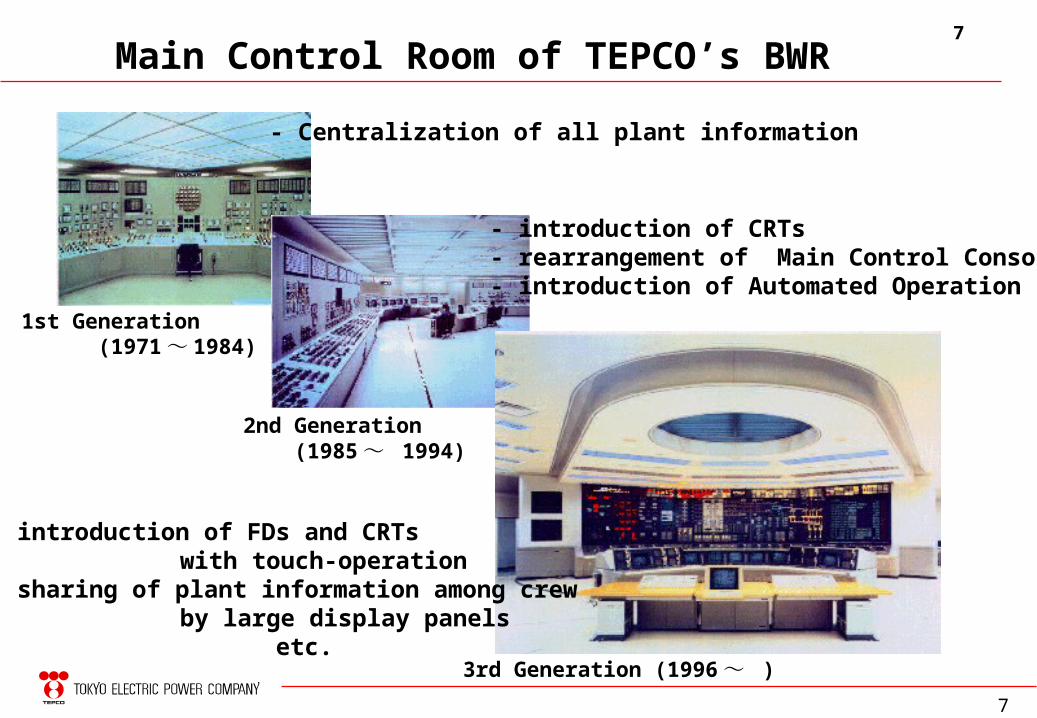
Main Control Room of TEPCO’s BWR
1st Generation (1971 ~ 1984)
2nd Generation (1985 ~ 1994)
3rd Generation (1996 ~ )
- Centralization of all plant information
- introduction of CRTs- rearrangement of Main Control Console- introduction of Automated Operation
- introduction of FDs and CRTswith touch-operation
- sharing of plant information among crewby large display panels
etc.
7
8
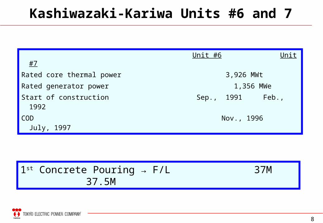
Kashiwazaki-Kariwa Units #6 and 7
1st Concrete Pouring → F/L 37M 37.5M
Unit #6 Unit #7
Rated core thermal power 3,926 MWt
Rated generator power 1,356 MWe
Start of construction Sep., 1991 Feb., 1992
COD Nov., 1996 July, 1997
9
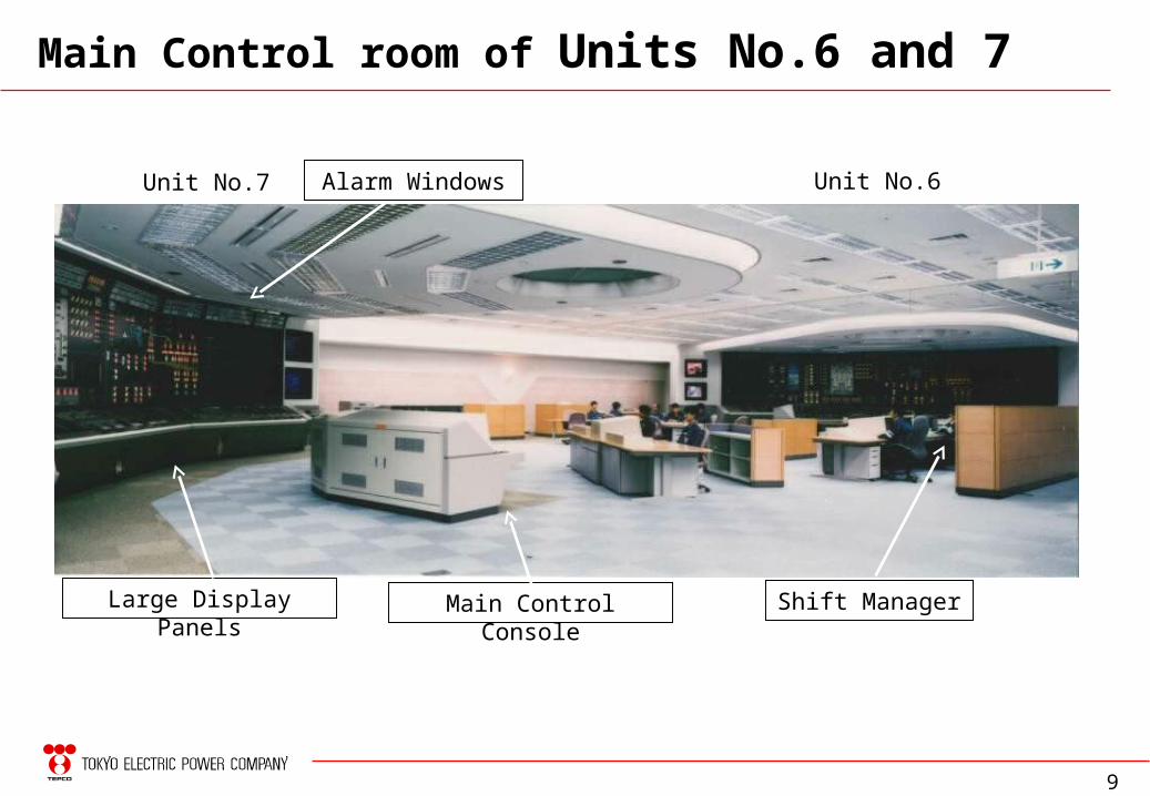
Main Control room of Units No.6 and 7
Unit No.6Unit No.7
Large Display Panels Main Control Console
Alarm Windows
Shift Manager
10
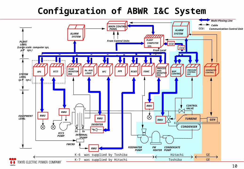
Configuration of ABWR I&C System
PLANTLEVEL(Large scale computer sys, μ-P sys.)
SYSTEMLEVEL
(μ-P sys.)
EQUIPMENTLEVEL
Rx. AUXLOGIC
ECCS BOP CONTROL
PRESSURECONTROLEHC
GENERATORCONTROLRPS
FLUX
ING
ECCSPUMP INTERNAL
PUMP
INVERTER
RMURMU
RMU FEEDWATERPUMP
FWHEATER
CONDENSATEPUMP
FMCRD
CONTROLVALVE
Multi-Plexing Line
Cable
PLANT
COMPUTER
SYS.
From Control Units
MAIN CONTROLPANEL
RC&IS
ALARMSYSTEM
APR FDWC RFC
ALARM
SYSTEM
K-6 was supplied by Toshiba Hitachi GE
K-7 was supplied by Hitachi Toshiba GE
RMU
RMUTURBINE
CONDENSER
GEN
From Local SignalsCCU
CCU: Communication Control Unit
MONITOR
RMU
RAD. MONITOR
PROCESS
ING
CCU
11
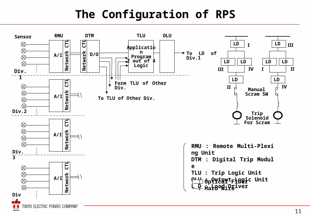
LD LD
ManualScram SW
Trip SolenoidFor Scram
Form TLU of Other Div.
To TLU of Other Div.
ApplicationProgram
2 out of 4Logic
Sensor
Div.1
Div.2
Div.3
Div.4
LD LD
LD LD LD LDA/I
A/I
A/I
A/I
RMU
D/O
Net
wor
k C
TL
Net
wor
k C
TL
Net
wor
k C
TL
Net
wor
k C
TL
Net
wor
k C
TL
DTM TLU OLU
The Configuration of RPS
To LD of Div.1
Ⅰ
Ⅰ
Ⅱ
Ⅱ
Ⅲ
Ⅲ
Ⅳ
Ⅳ
RMU : Remote Multi-Plexing UnitDTM : Digital Trip ModuleTLU : Trip Logic UnitOLU : Output Logic UnitL D : Load Driver
: Optical Fiber: Hard Wire
12
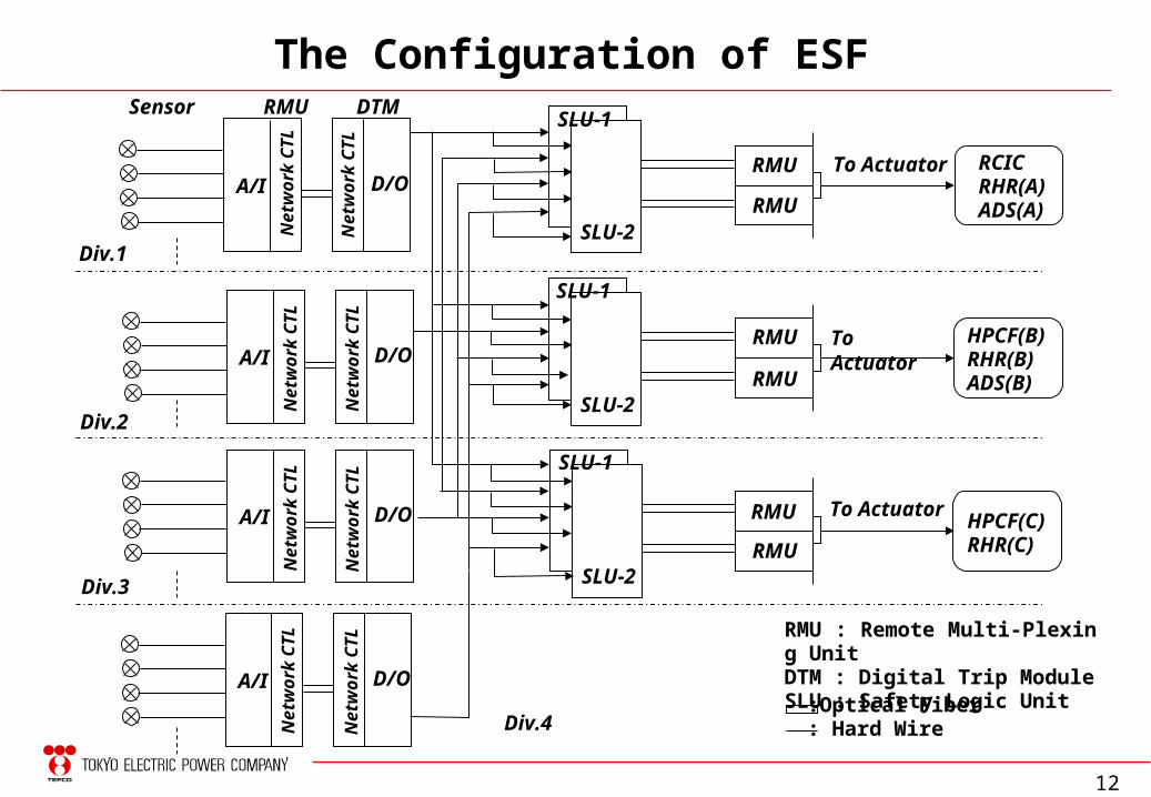
The Configuration of ESF
A/I D/O
A/I D/O
A/I D/O
A/I D/O
SLU-1
SLU-2
SLU-1
SLU-2
SLU-1
SLU-2
To Actuator
To Actuator
To Actuator
RMU RCICRHR(A)ADS(A)
HPCF(B)RHR(B)ADS(B)
HPCF(C)RHR(C)
Sensor RMU DTM
Div.1
Div.2
Div.3
Div.4
RMU
RMU
RMU
RMU
RMU
RMU : Remote Multi-Plexing UnitDTM : Digital Trip ModuleSLU : Safety Logic Unit
:Optical Fiber: Hard Wire
Net
wor
k C
TL
Net
wor
k C
TL
Net
wor
k C
TL
Net
wor
k C
TL
Net
wor
k C
TL
Net
wor
k C
TL
Net
wor
k C
TL
Net
wor
k C
TL
13
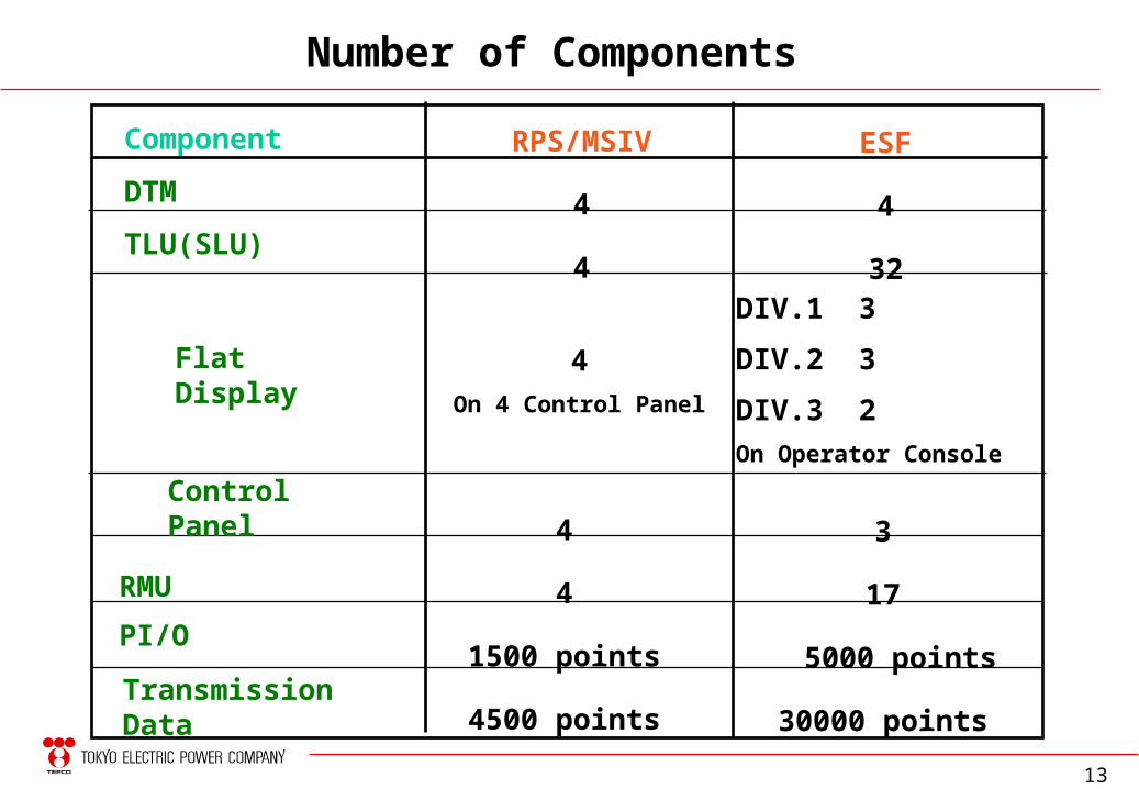
Number of Components
Component
DTM
TLU(SLU)
4
4
1500 points
4500 points
ESF
4
32DIV.1 3
DIV.2 3
DIV.3 2On Operator Console
RPS/MSIV
4
4
4On 4 Control Panel
3
17
5000 points
30000 points
Flat Display
ControlPanel
TransmissionData
RMU
PI/O
14
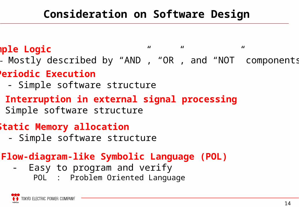
Simple Logic - Mostly described by “AND”, “OR”, and “NOT” components
Periodic Execution - Simple software structure
No Interruption in external signal processing - Simple software structure
Static Memory allocation - Simple software structure
Consideration on Software Design
Flow-diagram-like Symbolic Language (POL) - Easy to program and verify POL : Problem Oriented Language
15
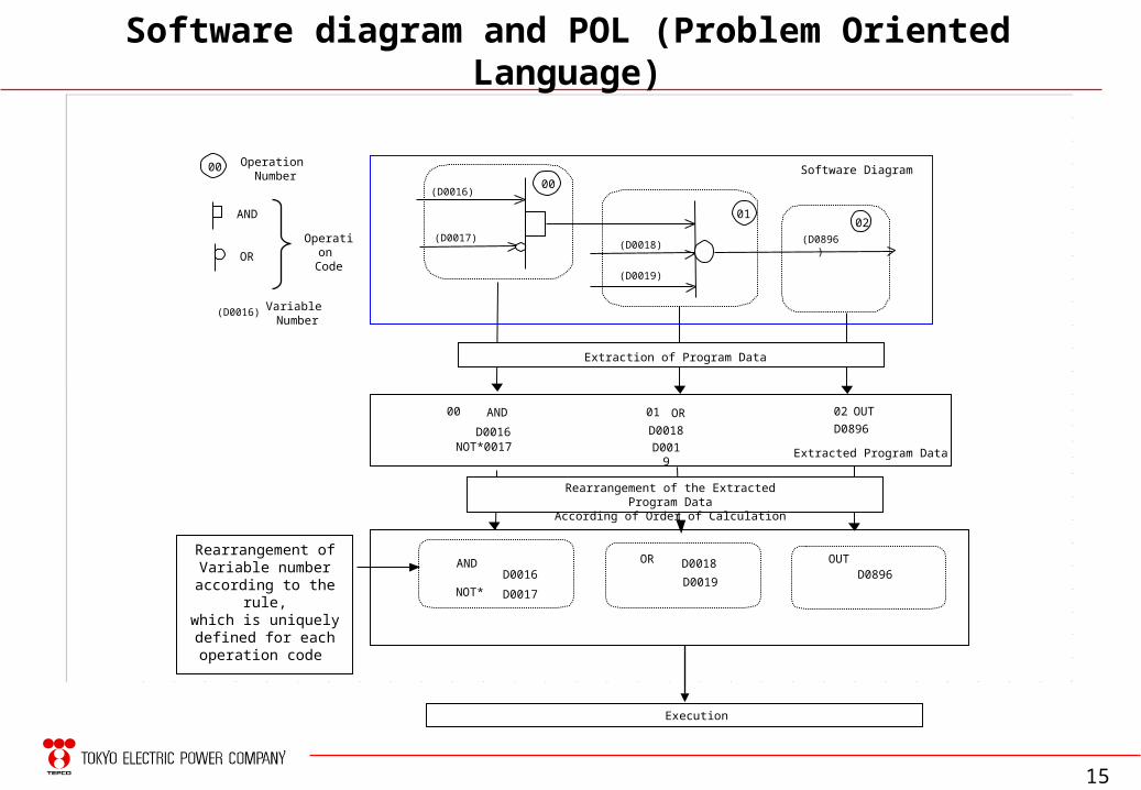
Software diagram and POL (Problem Oriented Language)
Rearrangement ofVariable number
according to the rule,which is uniquelydefined for eachoperation code
D0017
AND
NOT*
D0016D0019
OR D0018 OUTD0896
00 AND
D0016NOT*0017
01 OR
D0018
D0019
02 OUT
D0896
Extracted Program Data
Rearrangement of the Extracted Program DataAccording of Order of Calculation
(D0016)
(D0017)(D0018)
(D0019)
(D0896)
Software Diagram00
0102
Extraction of Program Data
Execution
00
(D0016) Variable Number
Operation Number
Operation Code
AND
OR
16
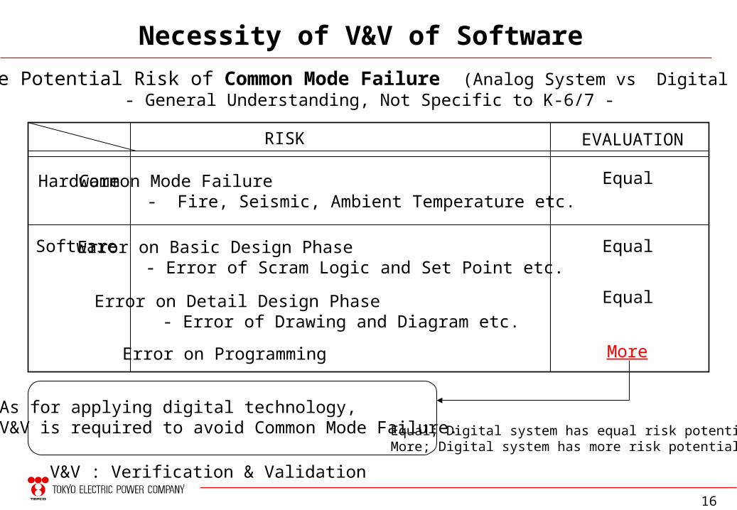
Necessity of V&V of Software
Compare Potential Risk of Common Mode Failure (Analog System vs Digital System)- General Understanding, Not Specific to K-6/7 -
Equal; Digital system has equal risk potential.More; Digital system has more risk potential.
Error on Basic Design Phase- Error of Scram Logic and Set Point etc.
Hardware
Software
RISK EVALUATION
Common Mode Failure- Fire, Seismic, Ambient Temperature etc.
Error on Detail Design Phase- Error of Drawing and Diagram etc.
Error on Programming
Equal
Equal
Equal
More
As for applying digital technology,V&V is required to avoid Common Mode Failure.
V&V : Verification & Validation
17
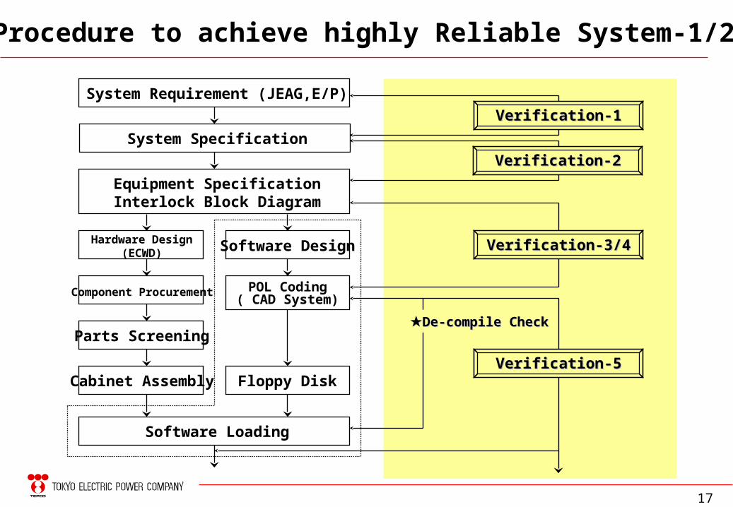
Procedure to achieve highly Reliable System-1/2
System Requirement (JEAG,E/P)
System Specification
Equipment SpecificationInterlock Block Diagram
Hardware Design(ECWD) Software Design
Component Procurement POL Coding( CAD System)
Parts Screening
Cabinet Assembly Floppy Disk
Software Loading
Verification-1Verification-1
Verification-2Verification-2
Verification-3/4Verification-3/4
Verification-5Verification-5
★★De-compile CheckDe-compile Check
18
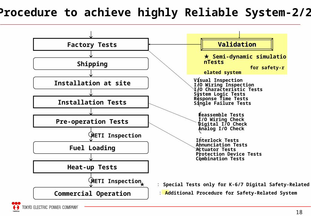
Factory Tests
Shipping
Procedure to achieve highly Reliable System-2/2
Installation at site
Installation Tests
Pre-operation Tests
Fuel Loading
METI Inspection
Heat-up Tests
Commercial Operation
METI Inspection
ValidationValidation
Visual InspectionI/O Wiring InspectionI/O Characteristic TestsSystem Logic TestsResponse Time TestsSingle Failure Tests
Reassemble TestsI/O Wiring CheckDigital I/O CheckAnalog I/O Check
Interlock TestsAnnunciation TestsActuator TestsProtection Device TestsCombination Tests
★ Semi-dynamic simulationTests for safety-related system
★ : Special Tests only for K-6/7 Digital Safety-Related System
: Additional Procedure for Safety-Related System
19
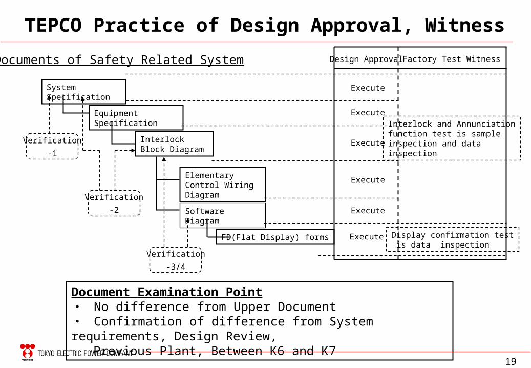
TEPCO Practice of Design Approval, Witness
Equipment Specification
System Specification
FD(Flat Display) forms
Interlock Block Diagram
Elementary Control Wiring Diagram
Documents of Safety Related System Design Approval Factory Test Witness
Document Examination Point・ No difference from Upper Document・ Confirmation of difference from System requirements, Design Review, Previous Plant, Between K6 and K7
Execute
Execute
Execute
Execute
Execute
Execute
Interlock and Annunciationfunction test is sampleinspection and data inspection
Display confirmation test is data inspection
Software Diagram
Verification
-3/4
Verification
-2
Verification
-1
20
TEPCO’s Philosophy to avoid CMF caused by software error
・ Software for safety system shall be easy to understand even for utility engineers.
・ Digital system and software for safety system shall be verified and validated easily.
・ TEPCO thought that POL was suitable language for V&V through long history of digital non safety system development.
・ TEPCO convinced that high reliable digital safety system could and should be built by POL, which is very simple and visual software, and strict QA activities.
・ V&V is conducted to demonstrate the reliability in auditable manner in addition to the strict QA activities.
# POL : Problem Oriented Language V&V : Verification & Validation
21
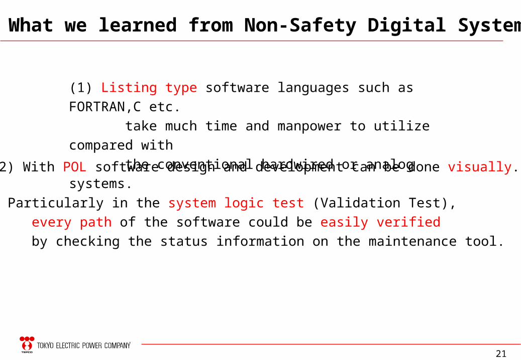
What we learned from Non-Safety Digital System
(1) Listing type software languages such as FORTRAN,C etc.
take much time and manpower to utilize compared with
the conventional hardwired or analog systems.
(2) With POL software design and development can be done visually.
(3) Particularly in the system logic test (Validation Test),
every path of the software could be easily verified
by checking the status information on the maintenance tool.
22
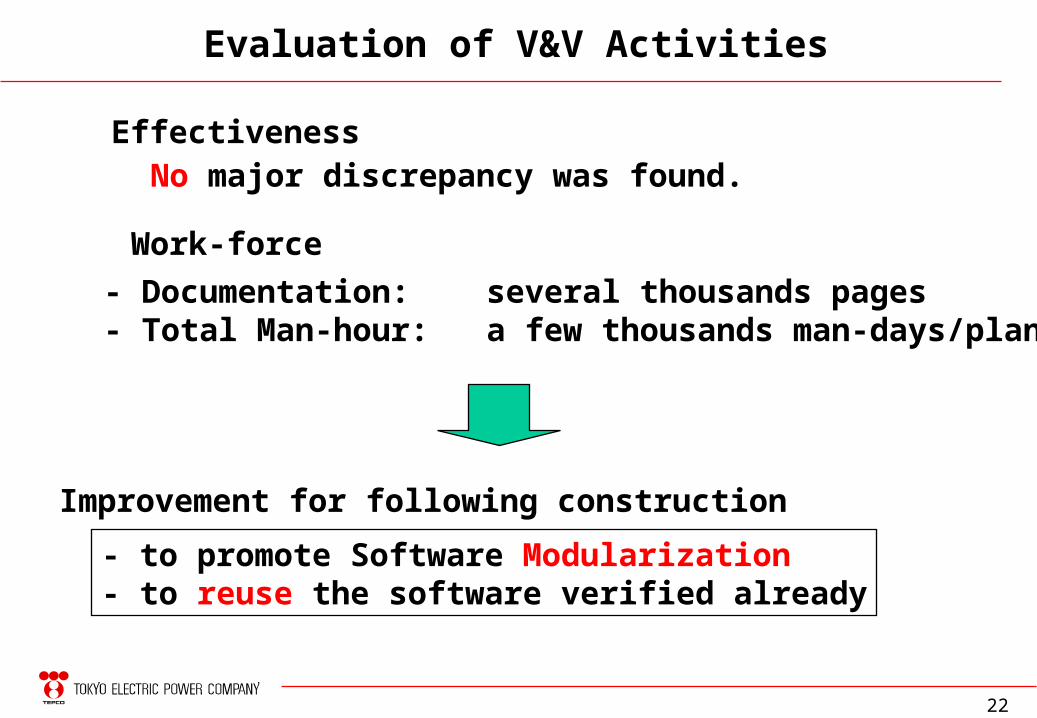
Evaluation of V&V Activities
EffectivenessNo major discrepancy was found.
Work-force
- Documentation: several thousands pages- Total Man-hour: a few thousands man-days/plant
Improvement for following construction
- to promote Software Modularization- to reuse the software verified already
23
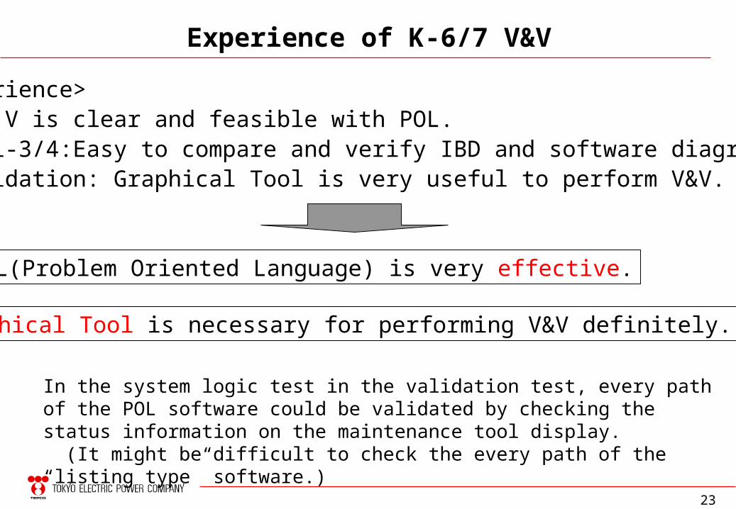
Experience of K-6/7 V&V
Graphical Tool is necessary for performing V&V definitely.
POL(Problem Oriented Language) is very effective.
<Experience> V & V is clear and feasible with POL. Veri-3/4:Easy to compare and verify IBD and software diagram. Validation: Graphical Tool is very useful to perform V&V.
In the system logic test in the validation test, every path of the POL software could be validated by checking the status information on the maintenance tool display. (It might be difficult to check the every path of the “listing type” software.)
24
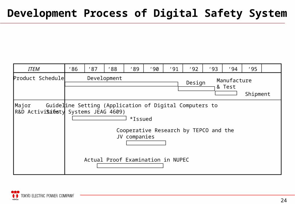
ITEM
Product Schedule
MajorR&D Activities
‘86 ‘87 ‘88 ‘89 ‘90 ‘91 ‘92 ‘93 ‘94 ‘95
DevelopmentDesign Manufacture
& TestShipment
Guideline Setting (Application of Digital Computers toSafety Systems JEAG 4609)
*Issued
Cooperative Research by TEPCO and theJV companies
Actual Proof Examination in NUPEC
Development Process of Digital Safety System
25
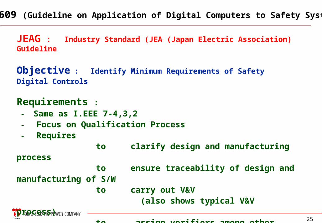
JEAG : Industry Standard (JEA (Japan Electric Association) Guideline
Objective : Identify Minimum Requirements of Safety Digital Controls
Requirements : - Same as I.EEE 7-4,3,2 - Focus on Qualification Process - Requires to clarify design and manufacturing process to ensure traceability of design and manufacturing of S/W to carry out V&V (also shows typical V&V process) to assign verifiers among other than designers to document V&V results
JEAG 4609 (Guideline on Application of Digital Computers to Safety Systems)
26
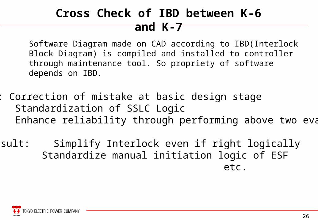
Cross Check of IBD between K-6 and K-7
Purpose: Correction of mistake at basic design stage Standardization of SSLC Logic Enhance reliability through performing above two evaluation
Result: Simplify Interlock even if right logically Standardize manual initiation logic of ESF
etc.
Software Diagram made on CAD according to IBD(Interlock Block Diagram) is compiled and installed to controller through maintenance tool. So propriety of software depends on IBD.
27
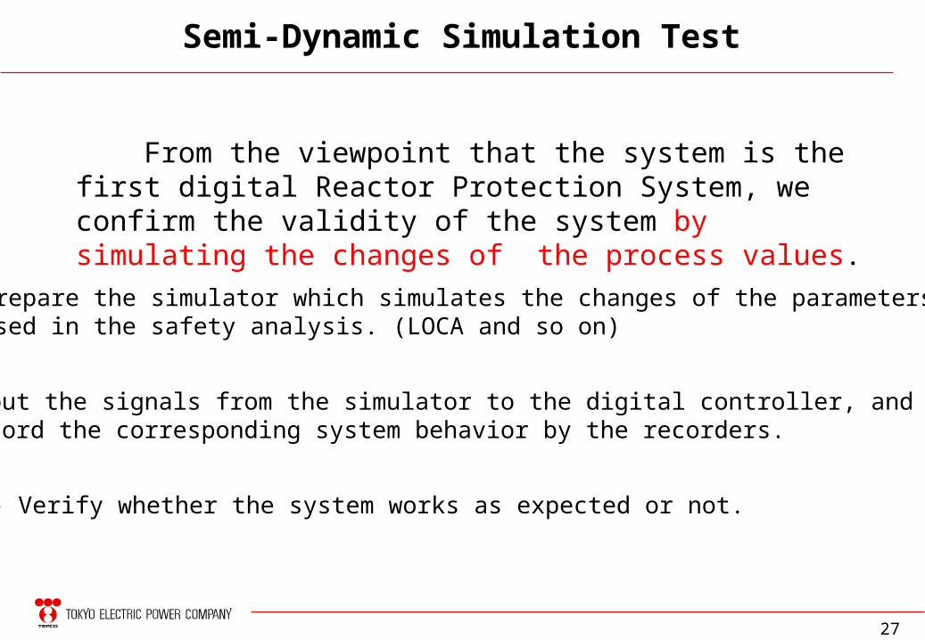
From the viewpoint that the system is the first digital Reactor Protection System, we confirm the validity of the system by simulating the changes of the process values.
- Prepare the simulator which simulates the changes of the parameters used in the safety analysis. (LOCA and so on)
- Input the signals from the simulator to the digital controller, and record the corresponding system behavior by the recorders.
- Verify whether the system works as expected or not.
Semi-Dynamic Simulation Test
28
ON
B21-MSIV-RST_01
OFF
2000
N11-PT001A_02
N11-PT001B_02
N11-PT001C_02 1000
N11-PT001D_02
0
ON
B21-SO-F002AA_01
OFF
ON
B21-SO-F002AB_01
OFF
0 10 20
0 10 20
Main turbine inlet pressure
Status of MSIV solenoid valve
Signals
Signals
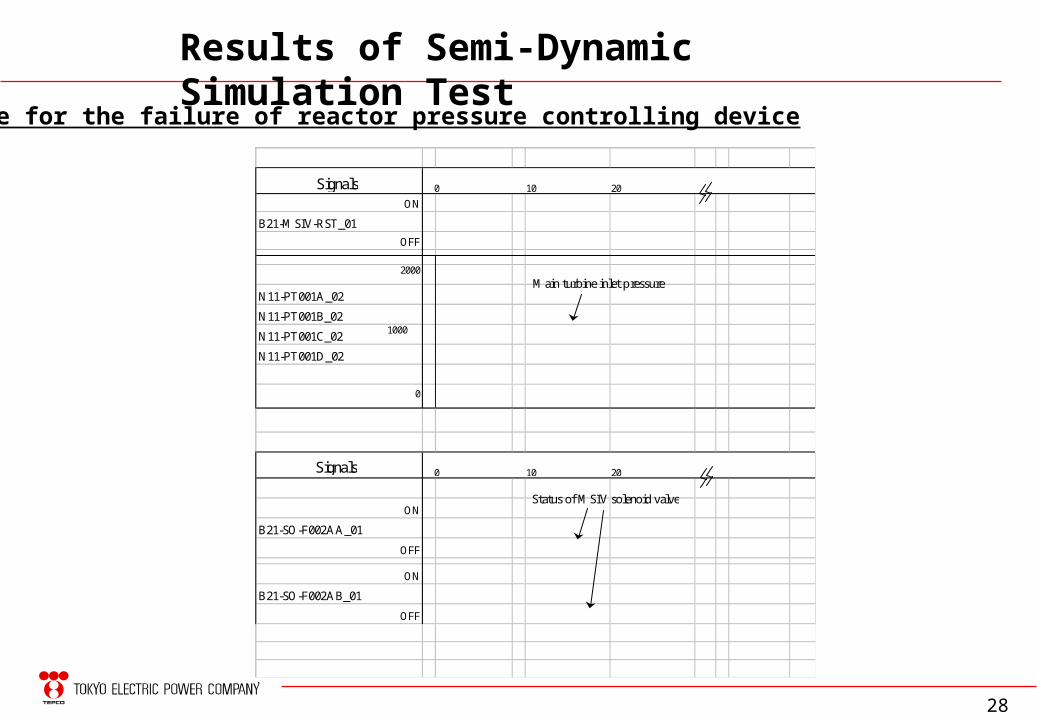
Results of Semi-Dynamic Simulation Test
Example for the failure of reactor pressure controlling device
29
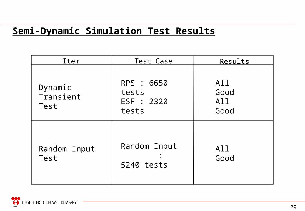
Semi-Dynamic Simulation Test Results
Item
Dynamic Transient Test
Random Input Test
Test Case Results
RPS : 6650 tests
ESF : 2320 tests
Random Input : 5240 tests
All Good
All Good
All Good
30
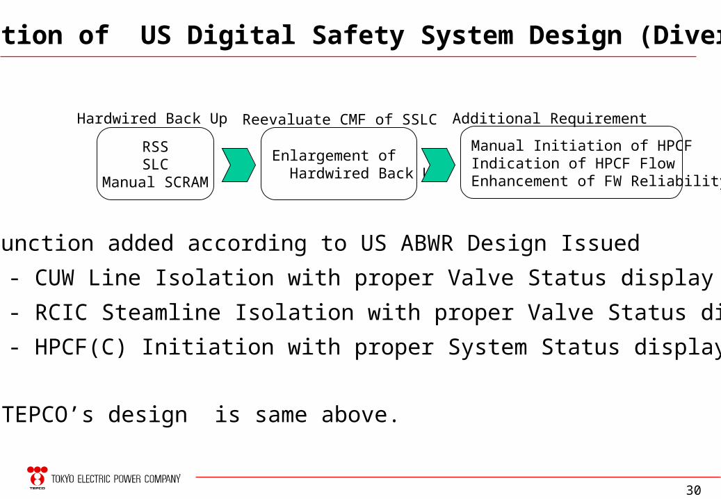
Transition of US Digital Safety System Design (Diversity)
* Function added according to US ABWR Design Issued
- CUW Line Isolation with proper Valve Status display
- RCIC Steamline Isolation with proper Valve Status display
- HPCF(C) Initiation with proper System Status display
RSSSLC
Manual SCRAM
Hardwired Back Up
Enlargement of Hardwired Back Up
Reevaluate CMF of SSLC
Manual Initiation of HPCFIndication of HPCF FlowEnhancement of FW Reliability
Additional Requirement
TEPCO’s design is same above.
31
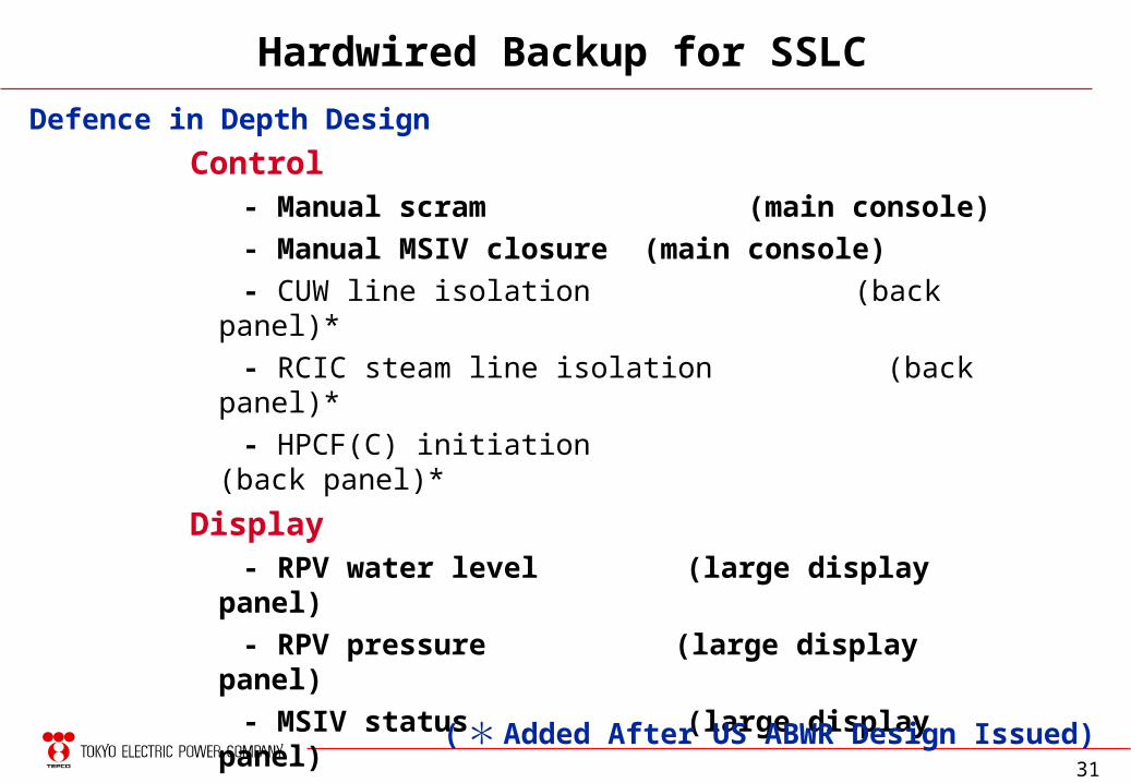
Hardwired Backup for SSLC
Control - Manual scram (main console)
- Manual MSIV closure (main console)
- CUW line isolation (back panel)*
- RCIC steam line isolation (back panel)*
- HPCF(C) initiation (back panel)*
Display - RPV water level (large display panel)
- RPV pressure (large display panel)
- MSIV status (large display panel)
- CUW isolation valve status (back panel)*
- RCIC isolation valve status (back panel)*
- HPCF(C) status (back panel)*
Defence in Depth Design
(* Added After US ABWR Design Issued)
32
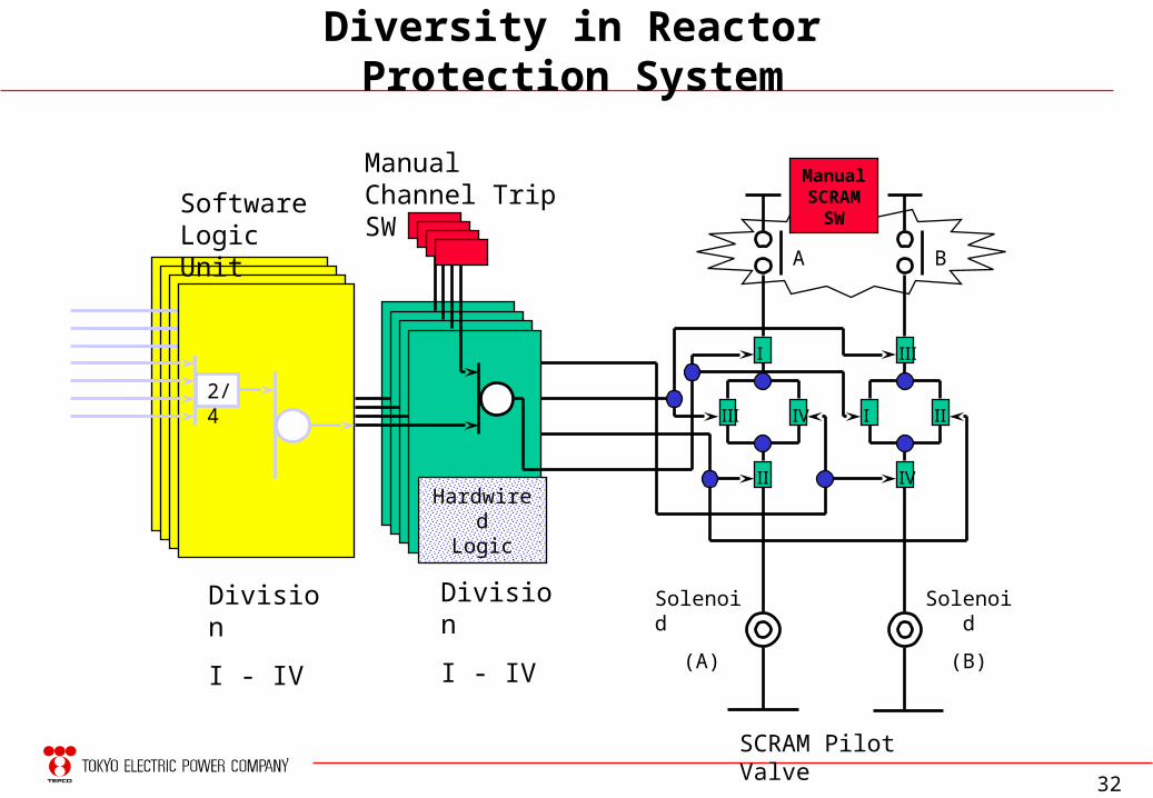
Diversity in Reactor Protection System
Ⅰ
Ⅱ
Ⅲ Ⅳ
Ⅰ
Ⅱ
Ⅲ
Ⅳ
Division
I - IV
2/42/4
2/42/4
ManualSCRAM
SWSoftware Logic Unit
HardwiredLogic
Manual Channel Trip SW
Solenoid
(A)
Solenoid
(B)
BA
SCRAM Pilot Valve
Division
I - IV
33
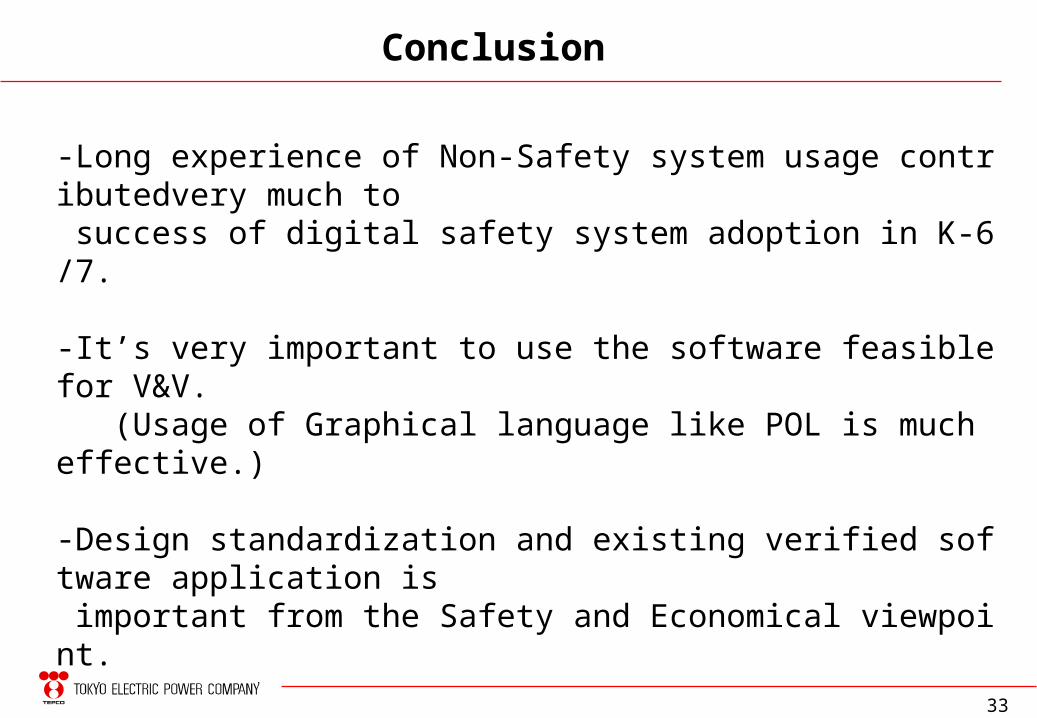
-Long experience of Non-Safety system usage contributedvery much to success of digital safety system adoption in K-6/7.
-It’s very important to use the software feasible for V&V. (Usage of Graphical language like POL is much effective.)
-Design standardization and existing verified software application is important from the Safety and Economical viewpoint.
- Considerations for common mode failure: The suitable backup measures against CMF should be applied.
Conclusion
34
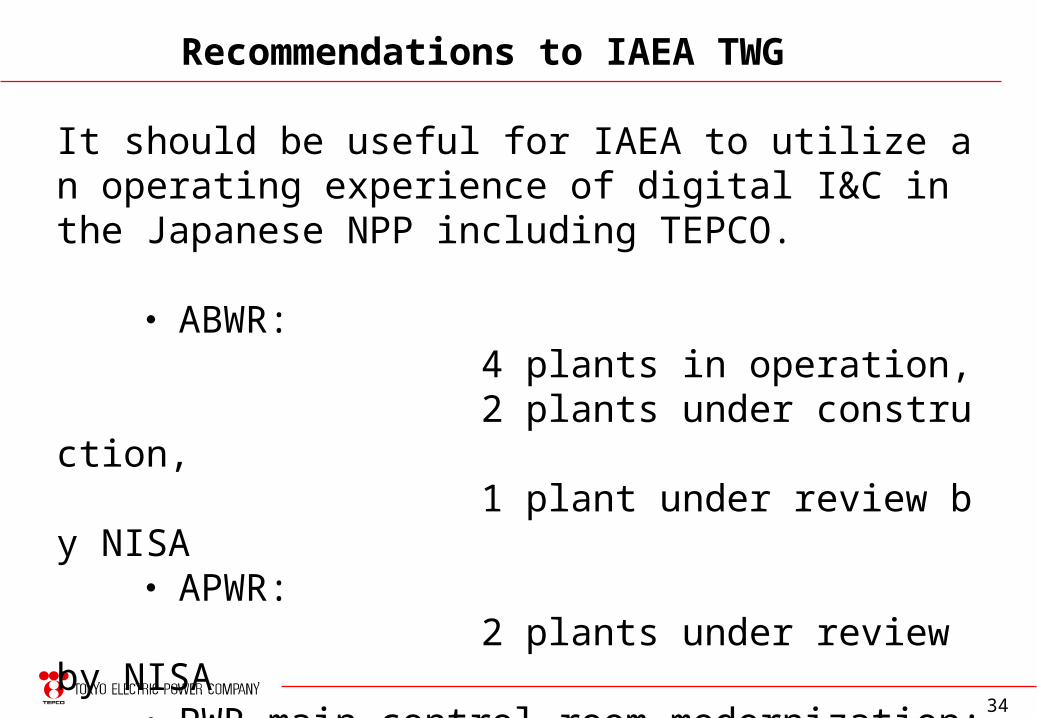
It should be useful for IAEA to utilize an operating experience of digital I&C in the Japanese NPP including TEPCO.
・ ABWR: 4 plants in operation, 2 plants under construction, 1 plant under review by NISA ・ APWR: 2 plants under review by NISA ・ PWR main control room modernization: 1 plant under construction (new unit), 2 plants under installation (existing units)
Recommendations to IAEA TWG
35
Thank you !
36
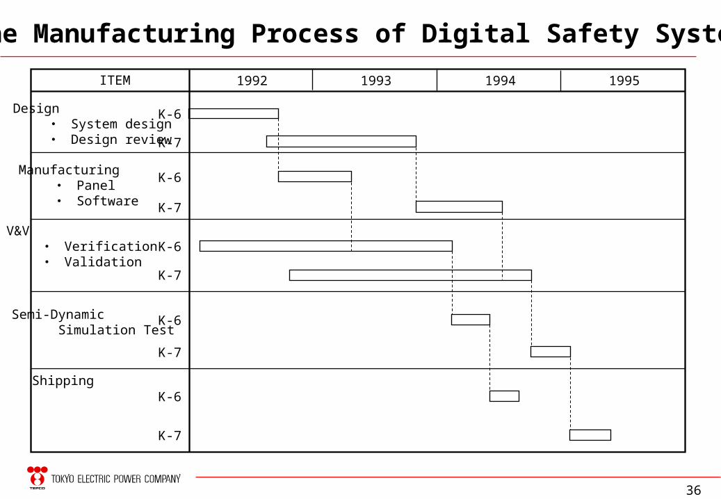
The Manufacturing Process of Digital Safety System
ITEM
Design ・ System design ・ Design review
1992 1993 1994
Semi-Dynamic Simulation Test
Manufacturing ・ Panel ・ Software
V&V ・ Verification ・ Validation
Shipping
1995
K-6
K-7
K-6
K-7
K-6
K-7
K-6
K-7
K-6
K-7
37
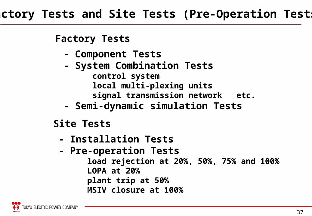
Factory Tests and Site Tests (Pre-Operation Tests)
Factory Tests
- Component Tests- System Combination Tests
control systemlocal multi-plexing unitssignal transmission network etc.
- Semi-dynamic simulation Tests
Site Tests
- Installation Tests- Pre-operation Tests
load rejection at 20%, 50%, 75% and 100%LOPA at 20%plant trip at 50%MSIV closure at 100%
38
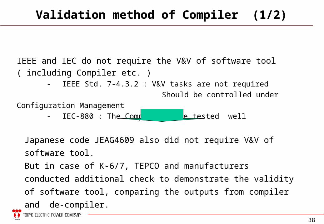
Validation method of Compiler (1/2)
IEEE and IEC do not require the V&V of software tool ( including Compiler etc. ) - IEEE Std. 7-4.3.2 : V&V tasks are not required
Should be controlled under Configuration Management
- IEC-880 : The Compiler to be tested well
Japanese code JEAG4609 also did not require V&V of software tool.
But in case of K-6/7, TEPCO and manufacturers conducted additional check to
demonstrate the validity of software tool, comparing the outputs from compiler
and de-compiler.
39
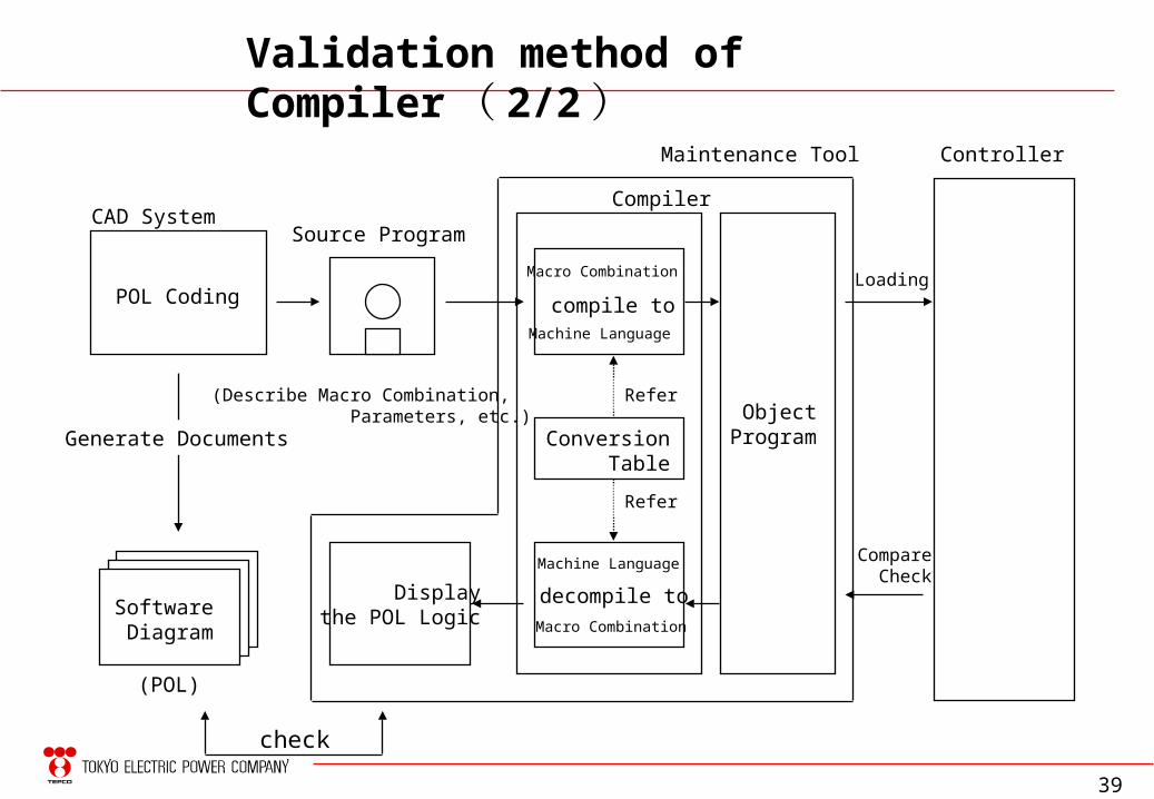
POL Coding
Software Diagram
(POL)
Maintenance Tool
Source Program
ObjectProgram
Compiler
Displaythe POL Logic
Controller
Macro Combination
Machine Language
compile to
Machine Language
Macro Combination
decompile to
Loading
Compare Check
Conversion Table
Refer
Refer
(Describe Macro Combination, Parameters, etc.)
check
CAD System
Validation method of Compiler ( 2/2 )
Generate Documents
40
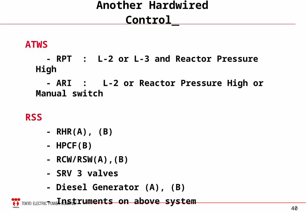
Another Hardwired Control
ATWS
- RPT : L-2 or L-3 and Reactor Pressure High
- ARI : L-2 or Reactor Pressure High or Manual switch
RSS
- RHR(A), (B)
- HPCF(B)
- RCW/RSW(A),(B)
- SRV 3 valves
- Diesel Generator (A), (B)
- Instruments on above system


![MUSICB PHILIP GLASSPHILIP GLASS [MISHIMA] ; • : [MISHIMA] PROGRAM IJ (Y a : Mishima/0pening Mishima Clos ing : Stand Alone PROFILE > NHK r IJ 2007 will 2008 —h 2009 Is CM 2010](https://static.fdocuments.us/doc/165x107/5e820171de10747e304fcfa9/musicb-philip-philip-glass-mishima-a-mishima-program-ij-y-a-mishima0pening.jpg)


![UK ABWR Generic Design Assessment - UK Advanced Boiling ...E10]UKABWR-GA... · Form10/00 . Hitachi-GE Nuclear Energy, Ltd. UK ABWR . UK ABWR Generic Design Assessment Alignment with](https://static.fdocuments.us/doc/165x107/5cc164e988c9936f648c4e74/uk-abwr-generic-design-assessment-uk-advanced-boiling-e10ukabwr-ga.jpg)