Construction analysis of mechanical parts of...
8
TEKA. COMMISSION OF MOTORIZATION AND ENERGETICS IN AGRICULTURE – 2013, Vol. 13, No.3, 162-169 Construction analysis of mechanical parts of locomotives Sergey Myamlin, Mukolaj Luchanin, Larysa Neduzha The Dniepropetrovsk National University of Railway Transport named after Academician V. Lazaryan, 2, Lazarian St., Dnepropetrovsk-10, 49700, Ukraine, e-mail: [email protected] Odessa railway, Ukraine Received May 31.2013: accepted July 02.2013 S u m m a r y . To determine the dynamic properties of the mainline freight locomotives, characterizing the safe movement on straight and curved sections of track in the whole range of operating speeds, you need a set of studies including selection of design scheme, the development of an appropriate mathematical model of spatial fluctuations of the locomotive, making a computer calculation program, conducting the theoretical, and then experimental investigations of new designs. In this case, one should compare the results with existing constructions. One of the necessary conditions for improving the quality of traction rolling stock is to define the parameters of its running gears. Among the questions related to this problem, an important place occupies the problem of determining dynamic qualities of the locomotives at the stages of design, taking into account with the chosen technical solutions in the running gear design. The work focuses on key tendencies of some types of main locomotives embodiment, focusing on improving the running gears design. As a result of investigations one can see that the creation of a modern locomotive requires from designers and scientists realization of scientific and technical solutions providing the design speed increase with simultaneous improvement of the traction, braking and dynamic qualities to provide the simple and reliable construction, especially construction of the running gear, reducing the operating costs, low original cost and operating costs for the total service life, high traction force during take-off, work capability in the multiple traction mode, maximally approximated to the limited clutch and sufficient design speed. Research of mathematical modeling is conducted by the method of numerical integration of the dynamic loading of the main-line locomotive using the software system «Dynamics of Rail Vehicles» («DYNRAIL»). Design features of the running gear elements of some types of the main-line locomotives, which have inclined rods between bogie and the body, transmitting the traction forces between them and providing essential dynamic performance of the carriage motion are studied. Key words. Locomotive, running gears, bogie, communication, inclined rods. INTRODUCTION To determine the dynamic properties of the mainline freight locomotives, characterizing the safe movement on straight and curved sections of track in the whole range of operating speeds, you need a set of studies including selection of design scheme, the development of an appropriate mathematical model of spatial fluctuations of the locomotive, making a computer calculation program, conducting the theoretical, and then experimental investigations of new designs. [1, 2, 3]. In this case, one should compare the results with existing constructions. One of the necessary conditions for improving the quality of traction rolling stock is to define the parameters of its running gears. Among the questions related to this problem, an important place occupies the problem of determining dynamic qualities of the locomotives at the stages of design, taking into account with the chosen technical solutions in the running gear design. The creation of a modern locomotive requires from designers and scientists the realization of scientific and technical solutions providing the design speed increase with simultaneous improvement of the traction, braking and dynamic properties [5, 6, 10, 11]. One should mark the following requirements: – A simple and reliable design, especially the running gears, which allows reducing maintenance and repair costs, – Low initial cost and operating cost for the total service-life,
Transcript of Construction analysis of mechanical parts of...

TEKA. COMMISSION OF MOTORIZATION AND ENERGETICS IN AGRICULTURE – 2013, Vol. 13, No.3, 162-169
Construction analysis of mechanical parts of locomotives
Sergey Myamlin, Mukolaj Luchanin, Larysa Neduzha
The Dniepropetrovsk National University of Railway Transport named after Academician V. Lazaryan, 2, Lazarian St., Dnepropetrovsk-10, 49700, Ukraine, e-mail: [email protected]
Odessa railway, Ukraine Received May 31.2013: accepted July 02.2013
S u m m a r y . To determine the dynamic properties of the mainline freight locomotives, characterizing the safe movement on straight and curved sections of track in the whole range of operating speeds, you need a set of studies including selection of design scheme, the development of an appropriate mathematical model of spatial fluctuations of the locomotive, making a computer calculation program, conducting the theoretical, and then experimental investigations of new designs. In this case, one should compare the results with existing constructions. One of the necessary conditions for improving the quality of traction rolling stock is to define the parameters of its running gears. Among the questions related to this problem, an important place occupies the problem of determining dynamic qualities of the locomotives at the stages of design, taking into account with the chosen technical solutions in the running gear design. The work focuses on key tendencies of some types of main locomotives embodiment, focusing on improving the running gears design. As a result of investigations one can see that the creation of a modern locomotive requires from designers and scientists realization of scientific and technical solutions providing the design speed increase with simultaneous improvement of the traction, braking and dynamic qualities to provide the simple and reliable construction, especially construction of the running gear, reducing the operating costs, low original cost and operating costs for the total service life, high traction force during take-off, work capability in the multiple traction mode, maximally approximated to the limited clutch and sufficient design speed. Research of mathematical modeling is conducted by the method of numerical integration of the dynamic loading of the main-line locomotive using the software system «Dynamics of Rail Vehicles» («DYNRAIL»). Design features of the running gear elements of some types of the main-line locomotives, which have inclined rods between bogie and the body, transmitting the traction forces between them and providing essential dynamic performance of the carriage motion are studied. K e y w o r d s . Locomotive, running gears, bogie, communication, inclined rods.
INTRODUCTION
To determine the dynamic properties of the mainline freight locomotives, characterizing the safe movement on straight and curved sections of track in the whole range of operating speeds, you need a set of studies including selection of design scheme, the development of an appropriate mathematical model of spatial fluctuations of the locomotive, making a computer calculation program, conducting the theoretical, and then experimental investigations of new designs. [1, 2, 3]. In this case, one should compare the results with existing constructions.
One of the necessary conditions for improving the quality of traction rolling stock is to define the parameters of its running gears. Among the questions related to this problem, an important place occupies the problem of determining dynamic qualities of the locomotives at the stages of design, taking into account with the chosen technical solutions in the running gear design.
The creation of a modern locomotive requires from designers and scientists the realization of scientific and technical solutions providing the design speed increase with simultaneous improvement of the traction, braking and dynamic properties [5, 6, 10, 11]. One should mark the following requirements:
– A simple and reliable design, especially the running gears, which allows reducing maintenance and repair costs,
– Low initial cost and operating cost for the total service-life,
CONSTRUCTION ANALYSIS OF MECHANICAL PARTS OF LOCOMOTIVES 163
– High traction when taking off maximally approximated to the limited clutch,
– Ability to work in multiple traction mode, – Sufficient design speed, – Easy control cabin with modern
management and monitoring means, – Unification of design and hardware
components within a small number of runs in order to simplify and reduce the cost of maintenance and repair, as well as to ensure the interoperability of locomotives belonging to different networks and companies.
Now let’s in more detail study the main tendencies of locomotive embodiment, focusing on improving the running parts design.
When improving the rolling stock design, generalization of theoretical, scientific, methodological and experimental studies aimed at further running parts improvement of some types of main-line locomotives promising designs is an urgent task. [4, 7]. It is known that the dynamic properties of the locomotive are determined by the size and distribution of the static deflections of the spring suspension and its damping capacity. It is believed that the use of a more flexible suspension reduces the amplitude of the additional loads in the carriages; for bogie locomotives a two-stage spring suspension is provided. On the basis of this requirement during the dynamic properties of locomotives research one should more thoroughly take into account the following characteristics:
– A body suspension on bogies; – Connection of body and bogie elements.
THE MAIN PART
In the end of the last century on Ukrainian railways were operated mostly physically and morally outdated locomotives. First of all it refers to electric locomotives VL8, produced since 1953, VL80 electric locomotives, which were launch in production in 1961, and some other locomotives. To provide the railway transport of Ukraine with more advanced electric locomotives the development of new designs is necessary. Therefore, the rational parameters definition of the freight electric locomotive underframe is an urgent task.
To develop a mathematical model of electric locomotive spatial oscillations and conduction of the following theoretical studies it is necessary to choose a design scheme.
To do this, we considered two schemes [8, 17]. The first is made on the basis of the electric locomotive VL85 design. This is one of the most
powerful mainline freight locomotives AC of that time (the design speed is 110 km/h) with a support and axial suspension of the traction motors, two-section twelve-axial electric locomotive with devices, providing operation according to a system of many units.
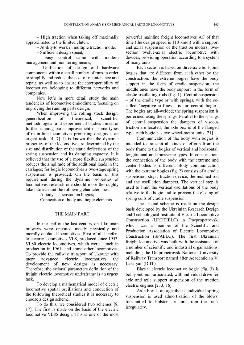
Each section is based on three-axle boll-joint bogies that are different from each other by the construction: the extreme bogies have the body support in the form of cradle suspension, the middle ones have the body support in the form of elastic oscillating rods (fig. 1). Central suspension – of the cradle type or with springs, with the so-called "negative stiffness" is for central bogies. The bogies are all-welded; the spring suspension is performed using the springs. Parallel to the springs of central suspension the dampers of viscous friction are located; the axle box is of the flanged type; each bogie has two wheel-motor units [21].
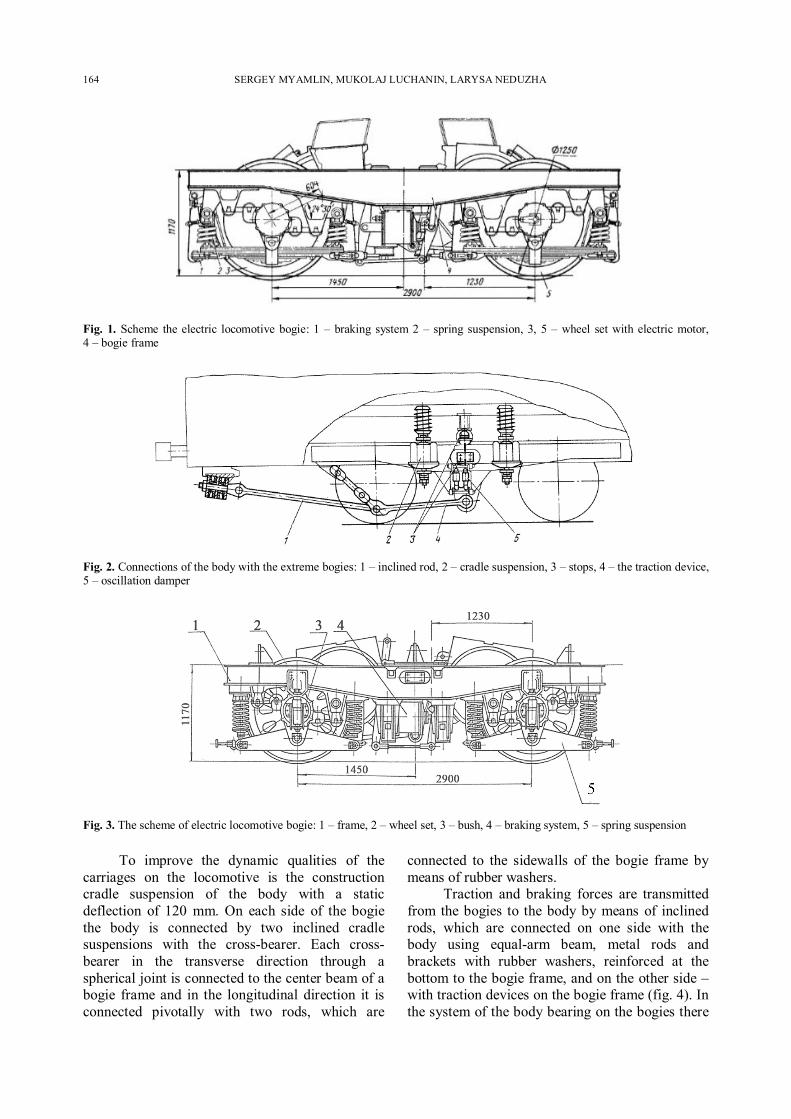
Communication of the body with bogies is intended to transmit all kinds of efforts from the body frame to the bogies of vertical and horizontal, longitudinal and transverse types. In construction, the connection of the body with the extreme and center bodies is different. Body communication with the extreme bogies (fig. 2) consists of a cradle suspension, stops, traction device, the inclined rod and the oscillation dampers. The vertical stop is used to limit the vertical oscillations of the body relative to the bogie and to prevent the closing of spring coils of cradle suspension.
The second scheme is made on the design basis developed by the Ukrainian Research Design and Technological Institute of Electric Locomotive Construction (URDTIELC) in Dnepropetrovsk, which was a member of the Scientific and Production Association of Electric Locomotive Construction (SPAELC). The first Ukrainian freight locomotive was built with the assistance of a number of scientific and industrial organizations, including the Dnipropetrovsk National University of Railway Transport named after Academician V. Lazaryan (DIIT).
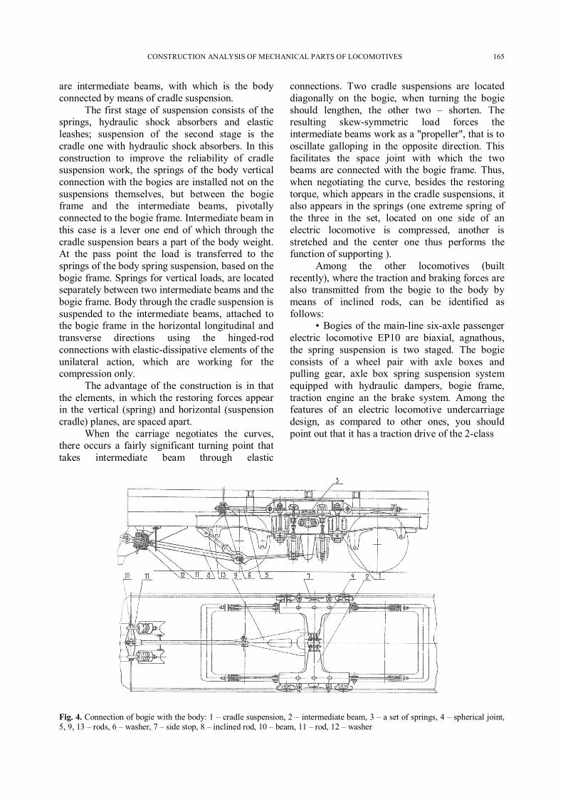
Biaxial electric locomotive bogie (fig. 3) is boll-joint, non-articulated, with individual drive for axle and axle support suspension of the traction electric engines [2, 3, 16].
Axle box is an agnathous; individual spring suspension is used admortization of the blows, transmitted to bolster structure from the track irregularity.
164 SERGEY MYAMLIN, MUKOLAJ LUCHANIN, LARYSA NEDUZHA
Fig. 1. Scheme the electric locomotive bogie: 1 – braking system 2 – spring suspension, 3, 5 – wheel set with electric motor, 4 – bogie frame
Fig. 2. Connections of the body with the extreme bogies: 1 – inclined rod, 2 – cradle suspension, 3 – stops, 4 – the traction device, 5 – oscillation damper
Fig. 3. The scheme of electric locomotive bogie: 1 – frame, 2 – wheel set, 3 – bush, 4 – braking system, 5 – spring suspension
To improve the dynamic qualities of the carriages on the locomotive is the construction cradle suspension of the body with a static deflection of 120 mm. On each side of the bogie the body is connected by two inclined cradle suspensions with the cross-bearer. Each cross-bearer in the transverse direction through a spherical joint is connected to the center beam of a bogie frame and in the longitudinal direction it is connected pivotally with two rods, which are
connected to the sidewalls of the bogie frame by means of rubber washers.
Traction and braking forces are transmitted from the bogies to the body by means of inclined rods, which are connected on one side with the body using equal-arm beam, metal rods and brackets with rubber washers, reinforced at the bottom to the bogie frame, and on the other side – with traction devices on the bogie frame (fig. 4). In the system of the body bearing on the bogies there
CONSTRUCTION ANALYSIS OF MECHANICAL PARTS OF LOCOMOTIVES 165
are intermediate beams, with which is the body connected by means of cradle suspension.
The first stage of suspension consists of the springs, hydraulic shock absorbers and elastic leashes; suspension of the second stage is the cradle one with hydraulic shock absorbers. In this construction to improve the reliability of cradle suspension work, the springs of the body vertical connection with the bogies are installed not on the suspensions themselves, but between the bogie frame and the intermediate beams, pivotally connected to the bogie frame. Intermediate beam in this case is a lever one end of which through the cradle suspension bears a part of the body weight. At the pass point the load is transferred to the springs of the body spring suspension, based on the bogie frame. Springs for vertical loads, are located separately between two intermediate beams and the bogie frame. Body through the cradle suspension is suspended to the intermediate beams, attached to the bogie frame in the horizontal longitudinal and transverse directions using the hinged-rod connections with elastic-dissipative elements of the unilateral action, which are working for the compression only.
The advantage of the construction is in that the elements, in which the restoring forces appear in the vertical (spring) and horizontal (suspension cradle) planes, are spaced apart.
When the carriage negotiates the curves, there occurs a fairly significant turning point that takes intermediate beam through elastic
connections. Two cradle suspensions are located diagonally on the bogie, when turning the bogie should lengthen, the other two – shorten. The resulting skew-symmetric load forces the intermediate beams work as a "propeller", that is to oscillate galloping in the opposite direction. This facilitates the space joint with which the two beams are connected with the bogie frame. Thus, when negotiating the curve, besides the restoring torque, which appears in the cradle suspensions, it also appears in the springs (one extreme spring of the three in the set, located on one side of an electric locomotive is compressed, another is stretched and the center one thus performs the function of supporting ).
Among the other locomotives (built recently), where the traction and braking forces are also transmitted from the bogie to the body by means of inclined rods, can be identified as follows:
• Bogies of the main-line six-axle passenger electric locomotive EP10 are biaxial, agnathous, the spring suspension is two staged. The bogie consists of a wheel pair with axle boxes and pulling gear, axle box spring suspension system equipped with hydraulic dampers, bogie frame, traction engine an the brake system. Among the features of an electric locomotive undercarriage design, as compared to other ones, you should point out that it has a traction drive of the 2-class
Fig. 4. Connection of bogie with the body: 1 – cradle suspension, 2 – intermediate beam, 3 – a set of springs, 4 – spherical joint, 5, 9, 13 – rods, 6 – washer, 7 – side stop, 8 – inclined rod, 10 – beam, 11 – rod, 12 – washer
166 SERGEY MYAMLIN, MUKOLAJ LUCHANIN, LARYSA NEDUZHA
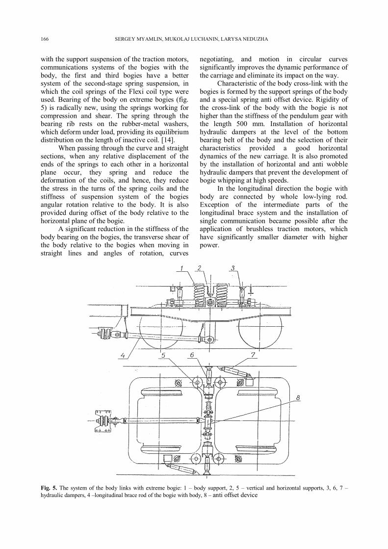
with the support suspension of the traction motors, communications systems of the bogies with the body, the first and third bogies have a better system of the second-stage spring suspension, in which the coil springs of the Flexi coil type were used. Bearing of the body on extreme bogies (fig. 5) is radically new, using the springs working for compression and shear. The spring through the bearing rib rests on the rubber-metal washers, which deform under load, providing its equilibrium distribution on the length of inactive coil. [14].
When passing through the curve and straight sections, when any relative displacement of the ends of the springs to each other in a horizontal plane occur, they spring and reduce the deformation of the coils, and hence, they reduce the stress in the turns of the spring coils and the stiffness of suspension system of the bogies angular rotation relative to the body. It is also provided during offset of the body relative to the horizontal plane of the bogie.
A significant reduction in the stiffness of the body bearing on the bogies, the transverse shear of the body relative to the bogies when moving in straight lines and angles of rotation, curves
negotiating, and motion in circular curves significantly improves the dynamic performance of the carriage and eliminate its impact on the way.
Characteristic of the body cross-link with the bogies is formed by the support springs of the body and a special spring anti offset device. Rigidity of the cross-link of the body with the bogie is not higher than the stiffness of the pendulum gear with the length 500 mm. Installation of horizontal hydraulic dampers at the level of the bottom bearing belt of the body and the selection of their characteristics provided a good horizontal dynamics of the new carriage. It is also promoted by the installation of horizontal and anti wobble hydraulic dampers that prevent the development of bogie whipping at high speeds.
In the longitudinal direction the bogie with body are connected by whole low-lying rod. Exception of the intermediate parts of the longitudinal brace system and the installation of single communication became possible after the application of brushless traction motors, which have significantly smaller diameter with higher power.
Fig. 5. The system of the body links with extreme bogie: 1 – body support, 2, 5 – vertical and horizontal supports, 3, 6, 7 – hydraulic dampers, 4 –longitudinal brace rod of the bogie with body, 8 – anti offset device
CONSTRUCTION ANALYSIS OF MECHANICAL PARTS OF LOCOMOTIVES 167
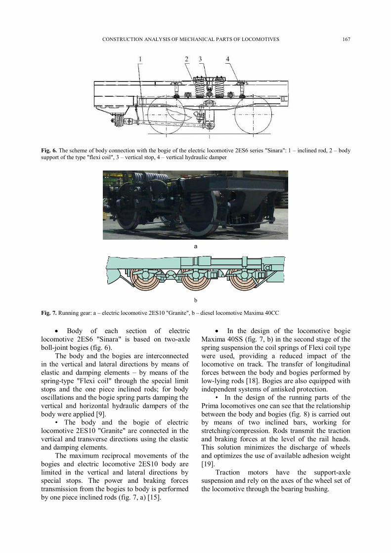
Fig. 6. The scheme of body connection with the bogie of the electric locomotive 2ES6 series "Sinara": 1 – inclined rod, 2 – body support of the type "flexi coil", 3 – vertical stop, 4 – vertical hydraulic damper
а
b
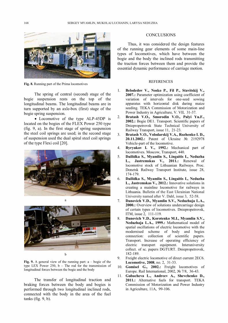
Fig. 7. Running gear: a – electric locomotive 2ES10 "Granite", b – diesel locomotive Maxima 40CC
Body of each section of electric locomotive 2ES6 "Sinara" is based on two-axle boll-joint bogies (fig. 6).
The body and the bogies are interconnected in the vertical and lateral directions by means of elastic and damping elements – by means of the spring-type "Flexi coil" through the special limit stops and the one piece inclined rods; for body oscillations and the bogie spring parts damping the vertical and horizontal hydraulic dampers of the body were applied [9].
• The body and the bogie of electric locomotive 2ES10 "Granite" are connected in the vertical and transverse directions using the elastic and damping elements.
The maximum reciprocal movements of the bogies and electric locomotive 2ES10 body are limited in the vertical and lateral directions by special stops. The power and braking forces transmission from the bogies to body is performed by one piece inclined rods (fig. 7, a) [15].
In the design of the locomotive bogie Maxima 40SS (fig. 7, b) in the second stage of the spring suspension the coil springs of Flexi coil type were used, providing a reduced impact of the locomotive on track. The transfer of longitudinal forces between the body and bogies performed by low-lying rods [18]. Bogies are also equipped with independent systems of antisked protection.
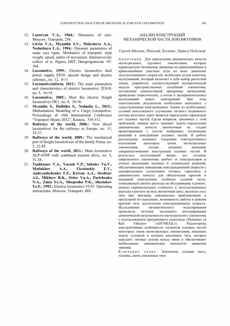
• In the design of the running parts of the Prima locomotives one can see that the relationship between the body and bogies (fig. 8) is carried out by means of two inclined bars, working for stretching/compression. Rods transmit the traction and braking forces at the level of the rail heads. This solution minimizes the discharge of wheels and optimizes the use of available adhesion weight [19].
Traction motors have the support-axle suspension and rely on the axes of the wheel set of the locomotive through the bearing bushing.
168 SERGEY MYAMLIN, MUKOLAJ LUCHANIN, LARYSA NEDUZHA
Fig. 8. Running part of the Prima locomotives
The spring of central (second) stage of the bogie suspension rests on the top of the longitudinal beams. The longitudinal beams are in turn supported by an axle-box (first) stage of the bogie spring suspension.
Locomotive of the type ALP-45DP is located on the bogies of the FLEX Power 250 type (fig. 9, a). In the first stage of spring suspension the steel coil springs are used; in the second stage of suspension used the dual spiral steel coil springs of the type Flexi coil [20].
а
b
Fig. 9. A general view of the running part: a – bogie of the type LEX Power 250, b – The rod for the transmission of longitudinal forces between the bogie and the body
The transfer of longitudinal traction and braking forces between the body and bogies is performed through two longitudinal inclined rods, connected with the body in the area of the fuel tanks (fig. 9, b).
CONCLUSIONS
Thus, it was considered the design features of the running gear elements of some main-line types of locomotives, which have between the bogie and the body the inclined rods transmitting the traction forces between them and provide the essential dynamic performance of carriage motion.
REFERENCES
1. Belodedov V., Nosko P., Fil P., Stavitskij V., 2007.: Parameter optimization using coefficient of variation of intervals for one-seed sowing apparatus with horizontal disk during maize seeding. TEKA Commission of Motorization and Power Industry in Agriculture, V. VII, 31-37.
2. Bratash V.O., Smorodin V.O., Palyi Yu.F., 2002.: Bogie DE1. Transport. Scientific papers of Dniepropetrovsk State Technical University of Railway Transport, issue 11, 21-23.
3. Bratash V.O., Volodarskij V.A., Rozhenko I. D., 20.11.2002.: Patent of Ukraine № 2192978 Vehicle-part of the locomotive.
4. Byryukov I. V., 1992.: Mechanical part of locomotives. Мoscow, Transport, 440.
5. Dailidka S., Myamlin S., Lingaitis L, Neduzha L., Jastremskas V., 2011.: Renewal of locomotive stock of Lithuanian Railways. Proc. Donetsk Railway Transport Institute, issue 28, 174-179.
6. Dailidka S., Myamlin S., Lingaitis L, Neduzha L., Jastremskas V., 2012.: Innovative solutions in creating a mainline locomotive for railways in Lithuania. Bulletin of the East Ukrainian National University named after V. Dahl, issue 3, 52-58.
7. Danovich V.D., Myamlin S.V., Neduzhaja L.A., 2000.: Overview of solutions undercarriage design of certain types of locomotives. Dniepropetrovsk, ITM, issue 2, 111-119.
8. Danovich V.D., Korotenko M.L, Myamlin S.V., Neduzhaja L.A., 1999.: Mathematical model of spatial oscillations of electric locomotive with the modernised scheme of body and bogies connection: collection of scientific papers. Transport. Increase of operating efficiency of electric transport equipment. Interuniversity collect. of sc. papers DGTURT. Dniepropetrovsk, 182-189.
9. Freight electric locomotive of direct current 2EC6. Locomotive, 2008, no. 2, 31-33.
10. Gomisel G., 2002.: Freight locomotives of Europe. Rail International, 2002, № 7/8, 36-43.
11. Gubacheva L., Andreev A., Shevchenko D., 2011.: Alternative fuels for transport. TEKA Commission of Motorization and Power Industry in Agriculture, 11A, 99-106.
CONSTRUCTION ANALYSIS OF MECHANICAL PARTS OF LOCOMOTIVES 169
12. Lazaryan V.A., 1964.: Dynamics of cars. Мoscow, Transport, 256.
13. Litvin V.A., Myamlin S.V., Malysheva A.A., Neduzhaya L.A., 1994.: Dynamic parameters of some cars types. Mechanics of transport: train weight, speed, safety of movement. Interuniversity collect. of sc. Papers, DIIT, Dniepropetrovsk 95-104.
14. Locomotive, 1999.: Electric locomotive dual power supply EP10: special design and electric schemes., no. 12, 9-11.
15. Locomotiveinform, 2012.: The main parameters and characteristics of electric locomotive 2ES10, no. 5, 16-19.
16. Locomotive, 2005.: Meet the electric freight locomotives DE1, no. 8, 34-36.
17. Myamlin S., Dailidka S., Neduzha L., 2012.: Mathematical Modeling of a Cargo Locomotive. Proceedings of 16th International Conference “Transport Means 2012”, Kaunas, 310-312.
18. Railways of the world, 2006.: New diesel locomotives for the railways in Europe, no. 11, 35-37.
19. Railways of the world, 2009.: The mechanical part of freight locomotives of the family Prima, no. 5, 32-45.
20. Railways of the world, 2011.: Main locomotive ALP-45DP with combined traction drive, no. 5, 31-38.
21. Tushkanov V.A., Yarosh V.P., Sobolev Yu.V., Matlakhov A.A., Ukrainskiy E.V., Andryushchenko T.F., Krivun A.A., Streltsov A.I., Mikheev B.K., Orlov Yu.A., Parichenko N.A., Zakis Ye.A., Shtepenko P.K., Shestakov Ye.F., 1992.: Electric locomotive VL85. Operating instructions. Moscow, Тransport, 480.
АНАЛИЗ КОНСТРУКЦИЙ МЕХАНИЧЕСКОЙ ЧАСТИ ЛОКОМОТИВОВ
Сергей Мямлин, Николай Луханин, Лариса Недужая
А н н о т а ц и я . Для определения динамических качеств магистральных грузовых локомотивов, которые характеризуют безопасное движение по прямолинейным и криволинейным участкам пути во всем диапазоне эксплуатационных скоростей, необходим целый комплекс исследований, который включает в себя выбор расчетной схемы, разработку соответствующей математической модели пространственных колебаний локомотива, составление компьютерной программы вычислений, проведение теоретических, а потом и экспериментальных исследований новых конструкций. При этом сопоставление результатов необходимо выполнить с существующими конструкциями. Одним из необходимых условий качественного улучшения тягового подвижного состава железных дорог является определение параметров его ходовых частей. Среди вопросов, связанных с этой проблемой, важное место занимает задача определения динамических качеств локомотивов на стадии проектирования с учетом выбранных технических решений в конструкции ходовых частей. В работе рассмотрены основные тенденции конструктивного исполнения некоторых типов магистральных локомотивов, уделив основное внимание совершенствованию конструкции ходовых частей. В результате исследований видно, что создание современного локомотива требует от конструкторов и ученых реализации научных и технических решений, обеспечивающих повышение конструкционной скорости с одновременным улучшением тяговых, тормозных и динамических качеств для обеспечения простой и надежной конструкции, особенно ходовой части, позволяющей снизить расходы на обслуживание и ремонт, низкую первоначальную стоимость и эксплуатационные расходы в расчете на весь жизненный цикл, высокую силу тяги при трогании, максимально приближенную к предельной по сцеплению, возможность работы в режиме кратной тяги, достаточную конструкционную скорость. Исследования математического моделирования проводятся методом численного интегрирования динамической нагруженности магистрального локомотива с использованием программного комплекса «Dynamics of Rail Vihicles» («DYNRAIL»). Рассмотрены конструктивные особенности элементов ходовых частей некоторых типов магистральных локомотивов, имеющих между тележкой и кузовом наклонные тяги, которые передают тяговые усилия между ними и обеспечивают необходимые динамические показатели движения экипажа. К л ю ч е в ы е с л о в а . Локомотив, ходовая часть, тележка, связи, наклонные тяги.